M38/68T-Kit Installation Instructions - Securitron Magnalock ...
M38/68T-Kit Installation Instructions - Securitron Magnalock ...
M38/68T-Kit Installation Instructions - Securitron Magnalock ...

You also want an ePaper? Increase the reach of your titles
YUMPU automatically turns print PDFs into web optimized ePapers that Google loves.
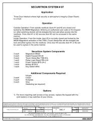
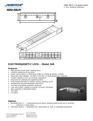
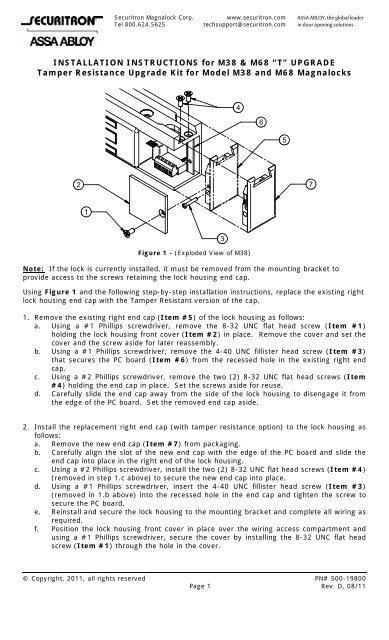
<strong>Securitron</strong> <strong>Magnalock</strong> Corp. www.securitron.com ASSA ABLOY, the global leaderTel 800.624.5625 techsupport@securitron.com in door opening solutionsINSTALLATION INSTRUCTIONS for <strong>M38</strong> & M68 “T” UPGRADETamper Resistance Upgrade <strong>Kit</strong> for Model <strong>M38</strong> and M68 <strong>Magnalock</strong>s465271Figure 1 - (Exploded View of <strong>M38</strong>)Note: If the lock is currently installed, it must be removed from the mounting bracket toprovide access to the screws retaining the lock housing end cap.Using Figure 1 and the following step-by-step installation instructions, replace the existing rightlock housing end cap with the Tamper Resistant version of the cap.1. Remove the existing right end cap (Item #5) of the lock housing as follows:a. Using a #1 Phillips screwdriver, remove the 8-32 UNC flat head screw (Item #1)holding the lock housing front cover (Item #2) in place. Remove the cover and set thecover and the screw aside for later reassembly.b. Using a #1 Phillips screwdriver, remove the 4-40 UNC fillister head screw (Item #3)that secures the PC board (Item #6) from the recessed hole in the existing right endcap.c. Using a #2 Phillips screwdriver, remove the two (2) 8-32 UNC flat head screws (Item#4) holding the end cap in place. Set the screws aside for reuse.d. Carefully slide the end cap away from the side of the lock housing to disengage it fromthe edge of the PC board. Set the removed end cap aside.32. Install the replacement right end cap (with tamper resistance option) to the lock housing asfollows:a. Remove the new end cap (Item #7) from packaging.b. Carefully align the slot of the new end cap with the edge of the PC board and slide theend cap into place in the right end of the lock housing.c. Using a #2 Phillips screwdriver, install the two (2) 8-32 UNC flat head screws (Item #4)(removed in step 1.c above) to secure the new end cap into place.d. Using a #1 Phillips screwdriver, insert the 4-40 UNC fillister head screw (Item #3)(removed in 1.b above) into the recessed hole in the end cap and tighten the screw tosecure the PC board.e. Reinstall and secure the lock housing to the mounting bracket and complete all wiring asrequired.f. Position the lock housing front cover in place over the wiring access compartment andusing a #1 Phillips screwdriver, secure the cover by installing the 8-32 UNC flat headscrew (Item #1) through the hole in the cover.© Copyright, 2011, all rights reserved PN# 500-19800Page 1 Rev. D, 08/11
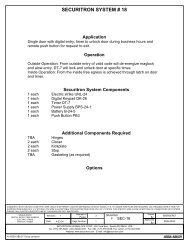
SERIES <strong>M38</strong> OR M68 WITH "T" OPTION(TAMPER INDICATION SWITCH)"T" OPTION OUTPUTSPDT DRY CONTACTACCESS CONTROL SYSTEMLOCK TAMPER STATUS INPUTNCCNO(RED)(WHITE)(BLUE)CONTACT RATING: 2 Amps @ 24 VoltsFigure 2 - (Wiring Diagram)INREFPN# 500-19800Page 2 Rev. D, 08/11