Colima Mec Magnetic Level Switches
Colima Mec Magnetic Level Switches
Colima Mec Magnetic Level Switches

You also want an ePaper? Increase the reach of your titles
YUMPU automatically turns print PDFs into web optimized ePapers that Google loves.
3.791.5275.200IM-P324-04CH Issue 3<strong>Colima</strong> <strong>Mec</strong><strong>Magnetic</strong> <strong>Level</strong> <strong>Switches</strong>Installation and Maintenance Instructions1. General safety information2. General product information3. Installation and Maintenance4. Spare parts5. Declaration of conformityE X P E R T I S E S O L U T I O N S S U S T A I N A B I L I T Y© Copyright 2012
1. General safety informationSafe operation of these products can only be guaranteed if they are properly installed,commissioned, used and maintained by qualified personnel (see Section 1.11) in compliancewith the operating instructions. General installation and safety instructions for pipeline andplant construction, as well as the proper use of tools and safety equipment must also becomplied with.1.1 Intended useReferring to the Installation and Maintenance Instructions, name-plate and Technical InformationSheet, check that the product is suitable for the intended use/application.The products comply with the requirements of the European Pressure Equipment Directives:ATEX 94 / 9 / CE and 97 / 23 / EC falling within category 'SEP'. It should be noted that productswithin this category are required by the Directive not to carry the mark.Products intended for use in the Naval and Marine sectors are RINA, and M.M.I (Italian navy)approved.i) The products have been specifically designed for use on steam, compressed air andinert industrial gases which are in Group 2 of the above mentioned Pressure EquipmentDirective. The products’ use on other fluids may be possible but, if this is contemplated,Spirax Sarco should be contacted to confirm the suitability of the product for the applicationbeing considered.ii) Check material suitability, pressure and temperature and their maximum and minimumvalues. If the maximum operating limits of the product are lower than those of the systemin which it is being fitted, or if malfunction of the product could result in a dangerousoverpressure or overtemperature occurrence, ensure a safety device is included in thesystem to prevent such over-limit situations.iii) Determine the correct installation situation and direction of fluid flow.iv) Spirax Sarco products are not intended to withstand external stresses that may be inducedby any system to which they are fitted. It is the responsibility of the installer to considerthese stresses and take adequate precautions to minimise them.v) Remove protection covers from all connections and protective film from all name-plates,where appropriate, before installation on steam or other high temperature applications.2 3.791.5275.200
1.2 AccessEnsure safe access and if necessary a safe working platform (suitably guarded) beforeattempting to work on the product. Arrange suitable lifting gear if required.1.3 LightingEnsure adequate lighting, particularly where detailed or intricate work is required.1.4 Hazardous liquids or gases in the pipelineConsider what is in the pipeline or what may have been in the pipeline at some previous time.Consider: flammable materials, substances hazardous to health, extremes of temperature.1.5 Hazardous environment around the productConsider: explosion risk areas, lack of oxygen (e.g. tanks, pits), dangerous gases, extremes oftemperature, hot surfaces, fire hazard (e.g. during welding), excessive noise, moving machinery.1.6 The systemConsider the effect on the complete system of the work proposed. Will any proposed action(e.g. closing isolation valves, electrical isolation) put any other part of the system or anypersonnel at risk?Dangers might include isolation of vents or protective devices or the rendering ineffective ofcontrols or alarms. Ensure isolation valves are turned on and off in a gradual way to avoidsystem shocks.1.7 Pressure systemsEnsure that any pressure is isolated and safely vented to atmospheric pressure. Considerdouble isolation (double block and bleed) and the locking or labelling of closed valves. Donot assume that the system has depressurised even when the pressure gauge indicates zero.1.8 TemperatureAllow time for temperature to normalise after isolation to avoid danger of burns and considerwhether protective clothing (inlcuding safety glasses) is required.1.9 Tools and consumablesBefore starting work ensure that you have suitable tools and/or consumables available. Useonly genuine Spirax Sarco replacement parts.1.10 Protective clothingConsider whether you and/or others in the vicinity require any protective clothing to protectagainst the hazards of, for example, chemicals, high/low temperature, radiation, noise, fallingobjects, and dangers to eyes and face.1.11 Permits to workAll work must be carried out or be supervised by a suitably competent person. Installationand operating personnel should be trained in the correct use of the product according tothe Installation and Maintenance Instructions. Where a formal 'permit to work' system is inforce it must be complied with. Where there is no such system, it is recommended that aresponsible person should know what work is going on and, where necessary, arrange tohave an assistant whose primary responsibility is safety. Post 'warning notices' if necessary.3.791.5275.2003
1.12 HandlingManual handling of large and/or heavy products may present a risk of injury. Lifting, pushing,pulling, carrying or supporting a load by bodily force can cause injury particularly to theback. You are advised to assess the risks taking into account the task, the individual, theload and the working environment and use the appropriate handling method depending onthe circumstances of the work being done.1.13 Residual hazardsIn normal use the external surface of the product may be very hot. If used at the maximumpermitted operating conditions the surface temperature of some products may reachtemperatures of 350°C.Many products are not self-draining. Take due care when dismantling or removing the productfrom an installation (refer to 'Maintenance instructions').1.14 FreezingProvision must be made to protect products which are not self-draining against frost damagein environments where they may be exposed to temperatures below freezing point.1.15 Safety information (Specific to the product)For any safety requirements relating to particular components and / or materials used inthe product construction, please refer to installation and maintenance instructions below.1.16 DisposalThis product is recyclable. No ecological hazard is anticipated with the disposal of thisproduct providing due care is taken.1.17 Returning productsCustomers and stockists are reminded that under EC Health, Safety and Environment Law,when returning products to Spirax Sarco they must provide information on any hazards andthe precautions to be taken due to contamination residues or mechanical damage which maypresent a health, safety or environmental risk. This information must be provided in writingincluding Health and Safetydata sheets relating to any substances identified as hazardous or potentially hazardous.4 3.791.5275.200
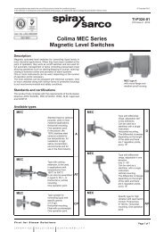
2. General product information2.1 DescriptionThe <strong>Colima</strong> MEC magnetic-activated level switch, are designed to control liquid levels of mostindustrial applications. When installed at the foreseen point of operation, they work as ON / OFFswitches for full automatic management of tanks (including pressurised ones) allowing operationssuch as starting / stopping of pumps, opening / closing of solenoid valves and activation of alarmsystems. One or more units can be used, depending on the number of operation points required.Mounting - <strong>Colima</strong> MEC magnetic level switch are side mounted directly in the tank.It can be installed vertically directly into the tank, or externally into a chamber connected to the tank.A square flange is specific for the naval industry.Standards and certification - The <strong>Colima</strong> MEC magnetic level switch complies with the followingEuropean Directives:- ATEX 94 / 9 / EC- European Pressure Equipment Directive PED 97 / 23 / EC- Products intended for use in the Naval and Marine sectors are RINA, and M.M.I (Italian navy)- Gost-R approved2.1.1 OperationThe level switch is secured to the tank by means of a flange. This supports a float with a pre-setpivoting axis. The float is integral with a sealed cartridge that contains a magnet.Two oscillating magnets on the same axis, one integral with the float and one integral with the electricalequipment, repel each other reciprocally through a non-magnetic material flange.The flange separates the housing, containing the electrical equipment, from the float that is insertedin the tank.The float automatically follows the level of the liquid, both in rising and in falling conditions.The switching of the electrical contact is quick and reliable.FlangeFulcrumMagneton floatsideMagneton contactside3.791.5275.2005
2.2 MaterialsNo. Part Material1 Housing Aluminium Epoxy coated / Stainless steel2 Contact SPDT / DPDT3 Flange304 / 316L / PVC / PP / PVDFLowest applicable nominal diameter 50 mm (2")with nominal pressure related to design needs.4 Float 04 / 316L / Monel / Hastelloy / PVC / PP / PVDF5 Chamber (not shown) A105 / 304 / 316L432 12.3 Design conditionsTMAPMAMaximumallowable temperatureMaximumallowable pressureFluid specific gravityDifferentialSteelPlasticSteelPlastic-20°C to + 150°Cwith cooling extension -20°C to + 350°CPVC -20°C to + 70°CPP -20°C to + 105°CPVDF -20°C to + 130°C<strong>Colima</strong>'s flange< 16 bar gflange sized according to rating < 100 bar g6 bar g≥ 0.8 kg/lonly CP type≥ 0.5 kg/lfixed 15 mmonly D and DV types ± 40°Materials and sizing are defined in relation to the characteristics of the liquid and the project conditions.6 3.791.5275.200
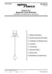
Models:MEC AStandard type for general purpose, used in mostindustrial applications.Horizontal mounting.One operation point.In the picture, the 100% stainless steel versions aresuitable for low temperatures, for installation in highsaline concentration environments and for use in thefood industry.MEC ATType with cooling extension, to be used in applicationswith temperatures from 150°C to 350°C.It can also be assembled in types D, DV, L and S.Horizontal or vertical mounting.One operation point.MEC CPType suitable for controlling liquid with specificgravity ≥ 0.5 kg / l.Horizontal mounting.Float with counterweight.One operation point.MEC DType with differential range, adjustable ±40° in twodirections.Can be used as a start / stop with a single instrument.Horizontal mounting.The differential increases depending on the length ofthe stem and there are 7 regulation points, every 15°.3.791.5275.2007
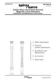
MEC DVType with differential range, adjustable in one direction,only 0 - 40°.Can be used as a start / stop with a single instrument.Vertical mounting.The differential increases depending on the length ofthe stem and there are 4 regulation points, every 15°.MEC AVSpecific type for high vibration with reed switch contact.Frequencies 5 - 100 Hz.Horizontal mounting.One operation point.MEC MType equipped with protection bellow to avoid anydeposits or inclusions present in the process liquid,eliminating risk of blockage.It can also be mounted on types D, DV, L and S.Horizontal mounting.One operation point.Stem length depending upon application.MEC OType indicated for sunken or difficult to access tanks(high or low level). Vertical mounting on pole in opentanks or in tanks with a manhole.Attention must be paid to the connection rating:float is 120 mm.One operation point, with field adstable start / stopfunction.Stem length depending upon application.8 3.791.5275.200
MEC PNPneumatic type, suitable in applications where there isno electrical supply.Stainless steel body with three way valve.Horizontal or vertical mounting.One operation point.MEC LType recommended in applications containing foam,inclusions and viscous fluids, where conditions requirethat the fulcrum point is not in touch with the processliquid.Vertical mounting.One operation point.Stem length depending upon application.MEC SType recommended in applications containing foam, inclusionsand viscous fluids, where conditions require thatthe fulcrum point is not in touch with the process liquid.Horizontal mounting.One operation point.Stem length depending upon application.MEC TType equipped with a device for field verification(operation checking).Mostly used in the naval industry.Can also be made in types L and S.Horizontal and vertical mounting.One operation point.Example of manual operation checking, to be carried out in the field.MEC MINISmall dimension type.Horizontal or vertical mounting.One operation point.IP54 and IP67protection degree.3.791.5275.2009
3. Installation and MaintenanceNote: Before actioning any installation or maintenance workobserve the 'Safety information' in Section 1.Refering to the Installation and Maintenance Instructions, name-plate and Technical InformationSheet, check that the product is suitable for the intended installation.Check: materials, pressure and temperature to ensure compatibility of the product with the requiredapplication. Also make sure that the ambient temperature in proximity of the device is between thevalues reported on the label (-20 - 40 ° C).Remove protective covers from all connections and the protective film from the name-plate.3.1 AssemblyThe <strong>Colima</strong> MEC magnetic level switches are delivered packed.Caution before installation disassemble the lower flange and remove the float from itspackage + Confirm the presence of supplied gaskets.3.1.1 Fit the level switch in the tank paying attention to avoid any damage at float.Any damage of the float can interfere with the correct operation of the unit.3.1.2 Place the supplied gasket between the flanges.3.1.3 Fix the flanges with bolts. Firmly secure the fixing by tightening the flange bolts.3.1.4 Ensure that there is nothing stopping the correct operation of the float.3.1.5 Open the unit housing and connect the wiring at the terminal board.The housing has one cable entry point (on demand and only for ATEX version two point):G ½" F, Explosion-proof Gk ½" F, ½" NPT F, M20 x 1.5, PG 13.5Caution: Always ensure that correct earthing of the equipment is carried out. Specific points areset inside and outside the housing.Explosion-proof housing operating limitsTechnical dataClass I: simple protective-earth connection requirementsEmployment data for potentially explosive atmospheresAmbient temperature limits-20°C to +50°CMarkingII 1/2 GD EEx d IIC T6 Ga/GbEEx tb IIIC T85°C Da/DbTemperature class T5 T4Permitted temperature variation range -20°C to +76°C -20°C to +104°CSuitability for the area of: 0, 1, 2, GAS Group II (Directive 99 / 92 / CE)Protection degreeIP67Warning:1. Do not make any modification to the housing. Any alterations or modifications to the product willinvalidate any warranties, explosion proof characteristics and any marking.2. Install at the inlet of the housing a suitable fixing or locking device with filling material.The absence of these components will result in the loss of responsibility of the manufacturer.3. These products should only be used for what they are designed for. Anything outside of thestipulated application range may be subject to unforeseen and dangerous circumstances andfull responsibility will be with the installer.4. Any accessories used for cable entries and for closing unused apertures shall be certifiedaccording to EN 60079-0, EN 60079-1, EN 61241-0, EN 61241-1 and be at least IP67.10 3.791.5275.200
3.1.6 Wiring: to connect SPDT o DPDT standard contact.SPDTDPDT (two simultaneouns SPDT contacts)Electrical contact characteristicsStandardWeather-proofStandard microswitch recommened for general purpose.Goldplated contacts in open air.Conctact coating:Galvanic in goldstandard 2 µspecial 5 µV ~ A = Load2203 2 Resistive1.5 0.5 Inductive306 3 Resistive3 1.5 Inductive<strong>Mec</strong>hanical life >10 6Electrical life >10 4Weather-proof microswitch. Goldplated contacts. IP66Nominal currentNominal voltageminimum 10 mAmaximum 400 mAminimum 5 Vmaximum 30 VFor oxidising environmentsFor high vibrationsV ~ A = Load2207 0.5 Resistive5 0.03 Inductive307 7 Resistive5 5 InductiveMicroswitch indicated for oxidising or corrosive environments.Goldplated contacts ermetically sealed in inert gas.V ~ A = Load2201 - Resistive- 0.4 Inductive303 - Resistive- 1.5 InductiveReed switch contact indicated for high vibrations, resists from5 to 100 Hz.30 g 11 ms.Goldplated contacts ermetically sealed in inert gas.Interruption power60 W / VASwitchable current1 ASwitchable voltage250 V3.791.5275.20011
3.2 DisassemblyBefore disassembly of the level switch disconnect or isolate any electricity supply or circuit anddepressurize the tank.Warning: do not disassemble the level switch before the tank has been emptied.3.2.1 Open the housing. For EEx-d housings wait at least five minutes before opening.3.2.2 Disconnect the electric circuit cables. Close the housing.3.2.3 Unscrew the connection bolts.3.2.4 Extract the level switch from the tank paying attention to avoid any damage to the float.Periodical inspections are necessary to guarantee complete efficiency of the unit. A regular maintenanceprogramme starting from its initial installation is recommended. The suggested precautions areimportant to obtain the best operating conditions of the level control.The instrument does not require preventive maintenance, however it is recommended that fromtime-to-time a check of the liquid fluidity is actioned to avoid any suspensions or deposits that caninfluence wetted parts. Also check that the float moves freely, in MEC-O version.Mounting accessoriesCounterflanges(Other sizes are available on request)Chamber for installation outside the tank*Depth of nippers*All types80 mmD and DV only35 mmMinimum distance between connectionsFlange300 mmOutput200 mm12 3.791.5275.200
The available spare parts are detailed below. No other parts are supplied as spares.Available spares4. Spare partsContacts 2Float 4How to order sparesAlways order spares by using the description given in the column headed 'Available spares' andstate the size and serial number of the unit which is indicated on the name-plate:Example: 1 off Float for a Spirax Sarco <strong>Colima</strong> MEC A having DN50 flanged ASME 150 RFconnections - Serial number 123456.423.791.5275.20013
5. Declaration of conformity“Hereinafter are listed the declarations of compliance that refer to standard products as well as theyare described in this instruction. For all that concerns special versions derived from the standard andprovided in response to specific order, our Certification and Testing Office will issue an individualdeclaration”.Flameproof (explosion-proof) enclosure for use in places at risk of explosion; the device is designedto be employed with process liquids that have a maximum operating temperature equal to 85°C.Electrical connections used for cable entries must have their own ATEX certification. During theconnection, make sure that the wires inside the enclosure are at a minimum distance of 3 mm fromthe housing wall.Electrical specifications230 Vac / 3 Aac110 Vcc / 0,5Acc24 Vcc / 1AccNumero dell'attestato CE del tipoIMQ 11 ATEX 033 X14 3.791.5275.200
3.791.5275.20015
16 3.791.5275.200
3.791.5275.20017
18 3.791.5275.200
3.791.5275.20019
REPAIRSPlease contact your nearest Spirax Sarco Branch Office or Agent, or directly to:Spirax Sarco S.r.l.Via per Cinisello, 18 - 20834 Nova Milanese (MB)Tel.: +39 0362 49 17.1Fax: +39 0362 49 17 307LOSS OF GUARANTEETotal or partial disregard of the above instructions involves loss of any rights to guarantee.Spirax-Sarco s.r.l. - Via per Cinisello, 18 - 20834 Nova Milanese (MB) - Tel.: +39 0362 49 17.1 - Fax +39 0362 49 17 3073.791.5275.200 CH Issue 3 - 2012.11