Model 2010 1-Axis Accelerometer - Silicon Designs, Inc.
Model 2010 1-Axis Accelerometer - Silicon Designs, Inc.
Model 2010 1-Axis Accelerometer - Silicon Designs, Inc.

You also want an ePaper? Increase the reach of your titles
YUMPU automatically turns print PDFs into web optimized ePapers that Google loves.
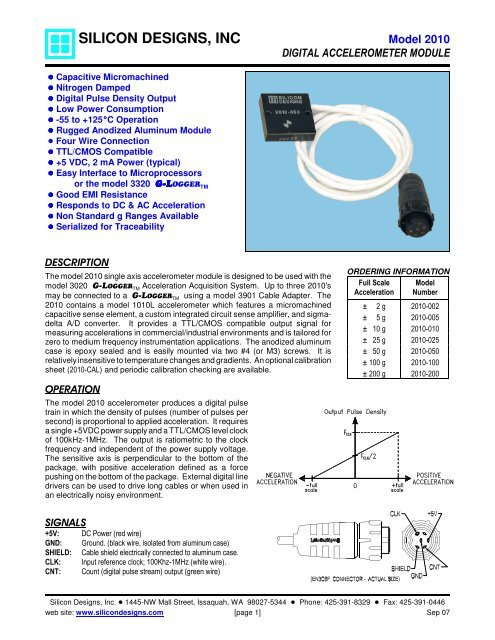
SILICON DESIGNS, INC <strong>Model</strong> <strong>2010</strong>DIGITAL ACCELEROMETER MODULE! Capacitive Micromachined! Nitrogen Damped! Digital Pulse Density Output! Low Power Consumption! -55 to +125EC Operation! Rugged Anodized Aluminum Module! Four Wire Connection! TTL/CMOS Compatible! +5 VDC, 2 mA Power (typical)! Easy Interface to Microprocessorsor the model 3320 G-LOGGER TM! Good EMI Resistance! Responds to DC & AC Acceleration! Non Standard g Ranges Available! Serialized for TraceabilityDESCRIPTIONThe model <strong>2010</strong> single axis accelerometer module is designed to be used with themodel 3020 G-LOGGER TM Acceleration Acquisition System. Up to three <strong>2010</strong>'smay be connected to a G-LOGGER TM using a model 3901 Cable Adapter. The<strong>2010</strong> contains a model 1010L accelerometer which features a micromachinedcapacitive sense element, a custom integrated circuit sense amplifier, and sigmadeltaA/D converter. It provides a TTL/CMOS compatible output signal formeasuring accelerations in commercial/industrial environments and is tailored forzero to medium frequency instrumentation applications. The anodized aluminumcase is epoxy sealed and is easily mounted via two #4 (or M3) screws. It isrelatively insensitive to temperature changes and gradients. An optional calibrationsheet (<strong>2010</strong>-CAL) and periodic calibration checking are available.OPERATIONThe model <strong>2010</strong> accelerometer produces a digital pulsetrain in which the density of pulses (number of pulses persecond) is proportional to applied acceleration. It requiresa single +5VDC power supply and a TTL/CMOS level clockof 100kHz-1MHz. The output is ratiometric to the clockfrequency and independent of the power supply voltage.The sensitive axis is perpendicular to the bottom of thepackage, with positive acceleration defined as a forcepushing on the bottom of the package. External digital linedrivers can be used to drive long cables or when used inan electrically noisy environment.ORDERING INFORMATIONFull Scale <strong>Model</strong>Acceleration Number± 2 g <strong>2010</strong>-002± 5 g <strong>2010</strong>-005± 10 g <strong>2010</strong>-010± 25 g <strong>2010</strong>-025± 50 g <strong>2010</strong>-050± 100 g <strong>2010</strong>-100± 200 g <strong>2010</strong>-200SIGNALS+5V:GND:SHIELD:CLK:CNT:DC Power (red wire)Ground. (black wire, isolated from aluminum case)Cable shield electrically connected to aluminum case.Input reference clock; 100Khz-1MHz (white wire).Count (digital pulse stream) output (green wire)<strong>Silicon</strong> <strong>Designs</strong>, <strong>Inc</strong>. ! 1445-NW Mall Street, Issaquah, WA 98027-5344 ! Phone: 425-391-8329 ! Fax: 425-391-0446web site: www.silicondesigns.com [page 1] Sep 07
ABSOLUTE MAXIMUM RATINGS *Operating Temperature (Case & Cable) . . . . -55 to +125ECOperating Temperature (Connector) . . . . . . . -40 to +65ECStorage Temperature . . . . . . . . . . . . . . . . . . . -40 to +65ECAcceleration Over-range . . . . . . . . . . . . . . 2000g for 0.1 msVoltage on V DD to GND . . . . . . . . . . . . . . . . . . -0.5V to 6.5VVoltage on CNT or CLK to GND 1 . . . . . . . . -0.5V to V DD +0.5VPower Dissipation . . . . . . . . . . . . . . . . . . . . . . . . . . . 50 mW* NOTICE: Stresses above those listed under "AbsoluteMaximum Ratings" may cause permanent damage to thedevice. These are stress ratings only. Functional operationof the device at or above these conditions is not implied.Exposure to absolute maximum rating conditions for extendedperiods may affect device reliability.ESD CONSIDERATIONS: The model <strong>2010</strong> accelerometer isa CMOS device subject to damage by large electrostaticdischarges. Diode protection is provided on the inputs andoutputs but care should be exercised during handling of theconnector or cable wire ends (without connector). Individualsand tools should be grounded before coming in contact withthe connector pins or cable wire ends (without connector).PERFORMANCE - by <strong>Model</strong>: V DD =5.0VDC, F CLK =250kHz, T C =25EC.<strong>Model</strong> <strong>2010</strong> Digital <strong>Accelerometer</strong> Module<strong>Model</strong> Number <strong>2010</strong>-002 <strong>2010</strong>-005 <strong>2010</strong>-010 <strong>2010</strong>-025 <strong>2010</strong>-050 <strong>2010</strong>-100 <strong>2010</strong>-200 UnitsInput Range ±2 ±5 ±10 ±25 ±50 ±100 ±200 gFrequency Response (Nominal, 3 dB) 0 - 400 0 - 600 0 - 1000 0 - 1400 0 - 1600 0 - 1800 0 - 2000 HzSensitivity (F CLK =250kHz) 62.5 25.0 12.5 5.00 2.50 1.25 0.625 kHz/gMax. Mechanical Shock (0.1 ms) 2000 gPERFORMANCE - all <strong>Model</strong>s: Unless otherwise specified V DD =5.0 VDC, F CLK =250kHz, T C =25EC.PARAMETER MIN TYP MAX UNITSCross <strong>Axis</strong> Sensitivity 2 3 %Bias Calibration Error 2 -002 2 4-005 thru -200 1 2% of F CLK (span)Bias Temperature Shift-002 150 400(T C = -55 to +125EC) 2 -005 thru -200 100 300(ppm of F CLK )/ECScale Factor Calibration Error 2, 3 1 2 %Scale Factor Temperature Shift (T C = -55 to +125EC) 2 +300 ppm/ECNon-Linearity-002 thru -100 0.5 1.0(-90 to +90% of Full Scale) 2, 3 -200 0.7 1.5% of spanPower Supply Rejection Ratio 40 dBOperating Voltage 4.5 5.0 5.5 VoltsOperating Current 2 2 3 mAClock Input Voltage Range (with respect to GND) -0.5 V DD +0.5 VoltsMass (not including cable) 8 gramsCable Mass 25 grams/meterNotes:1. Voltages on the CLK & CNT signal wires may exceed 0.5 volt above or below thesupply voltage provided the current into or out of the wire is limited to 1 mA.2. Tighter tolerances available on special order.3. 100g versions and above are tested from -65 to +65g.CONNECTOR: Switchcraft model EN3C6F (mating connector EN3L6M).ALTERNATE OUTPUT VERSION AVAILABLE: A custom version may be ordered which provides the DIR (direction) outputinstead of the CNT (count) output. For a description of the DIR signal, see the model 1010 data sheet.SPECIFICATIONS SUBJECT TO CHANGE WITHOUT NOTICE<strong>Silicon</strong> <strong>Designs</strong>, <strong>Inc</strong>. ! 1445-NW Mall Street, Issaquah, WA 98027-5344 ! Phone: 425-391-8329 ! Fax: 425-391-0446web site: www.silicondesigns.com [page 2] Sep 07
SIGNAL DESCRIPTIONS<strong>Model</strong> <strong>2010</strong> Digital <strong>Accelerometer</strong> ModuleCLK (input): Reference clock input. This hysteresis threshold input must be driven by a 50% duty cycle square wavesignal. Factory Calibration is performed at 250 kHz but the 2210 will operate at frequencies as low as 100 kHz or ashigh as 1 MHz.CNT (output): Count output. A return-to-zero type digital pulse stream whose pulse width is equal to the input CLK logichigh time. The CNT pulse rate increases with positive acceleration. The device experiences positive (+1g)acceleration with its lid facing up in the earth’s gravitational field. This signal is meant to drive an up-counter directly.Pulses from the CNT output are meant to be accumulated in a hardware counter. Each pulse accumulation or sample,reflects the average acceleration (change in velocity) over that interval. The sample period or “gate time” over which thesepulses are accumulated determines both the bandwidth and quantization of the measurement.Quantization (g' s) =gfCNTFORCEgSPAN• fSR⎛ 1 g= fCLK⎜ +⎝ 2 g⎛ fCNT= gSPAN⎜ −⎝ ffCLKCLKFORCESPAN1⎞⎟2⎠⎞⎟⎠Where:ggSPANfffSRCLKCNTFORCE=====1 g =2 *(full scale acceleration in g' sCNT sample rate in Hertzaccelerometer clock rate in HertzCNT pulse rate in pulses / secacceleration in gravity units9.807 m / s 2 or 32.175ft / s 2)The first equation above shows that as the sample rate is reduced (i.e. a longer sample period), the quantization becomesfiner but bandwidth is reduced. Conversely, as the sample rate is increased, quantization becomes coarser but thebandwidth of the measurement is increased. The second and third equations show how the CNT pulse frequency equatesto the applied g-force. When using a frequency counter to monitor the CNT output pulse rate, a counter with a DC coupledinput must be used. The CNT output is a return-to-zero signal whose duty cycle varies from zero to fifty percent, from minusfull scale to positive full scale acceleration. A frequency counter with an AC coupled input will provide an erroneousreading as the duty cycle varies appreciably from fifty percent.CABLE LENGTH CONSIDERATIONSCable lengths of up to 45 meters (150 feet) can be added to the model <strong>2010</strong>'s standard 1 meter cable when it is connectedto a <strong>Model</strong> 3901 Adapter Cable and is being used with a <strong>Model</strong> 3320 G-L-LOGGER TM . The extension cable must however,be a longer version of the G-L-LOGGER TM 9 conductor flat cable instead of the <strong>2010</strong>'s round cable to reduce crosstalkbetween the CNT and CLK signals. 15 meter (50 foot) cable lengths of DB9 male to DB9 female flat extension cable areavailable on special order.<strong>Silicon</strong> <strong>Designs</strong>, <strong>Inc</strong>. ! 1445-NW Mall Street, Issaquah, WA 98027-5344 ! Phone: 425-391-8329 ! Fax: 425-391-0446web site: www.silicondesigns.com [page 3] Sep 07