Measuring Technique - Premium
Measuring Technique - Premium
Measuring Technique - Premium

Create successful ePaper yourself
Turn your PDF publications into a flip-book with our unique Google optimized e-Paper software.
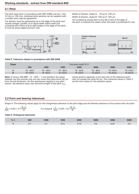
Working standards - extract from DIN standard 8663.1 PitchThe pitch step (term in accordance with DIN 2268) may be 1 mm,10 mm or 100 mm, individual pitch sections can be supplied witha smaller pitch step by agreement.The division must be penetrating up to the edge of the pitch andvisually straight, parallel, of an equal width within itself andcompared with others and at right angles to the edge of the pitch.It must be sharp-edged and burr-free.Width of division, shape A: 70 up to 100 µmWidth of division, shape B: 100 up to 150 µmThe numbering should start at the left at zero if the edge ofthe pitch is towards the viewer when the scale is positioned for use.Table 2. Tolerance classes in accordance with DIN 2268ShapeTotal given length l N, O500 1000 1500 2000 3000 4000 5000A TK 40/0 TK 40/0 TK 60/0 TK 60/0 TK 80/0 TK 100/0 TK 120/0B TK 100/0 TK 100/0 TK 150/0 TK 150/0 TK 200/0 TK 250/0 TK 300/0Note: If using a DIN 866 – A – 500 – 1 line standard, the spacebetween any two pitches may not vary more than plus/minus 40 µmfrom the set dimension. As this requirement applies to any pitchsection, the deviation span over the entire length of the pitch f max ,whose position depends on the zero line of the reference point,may not exceed the value 40 µm. The numerical values in Table 2are the limit values for the deviation spans.3.2 Form and bearing tolerancesShape A: The following values apply for the straightness tolerance of the pitch edge and the flatness tolerance of the surface with the pitch:t l N, O.= 0.02 + 0.1mmmt l N, O.For shape B = 0.04 + 0.2mmmTable 3. Orthogonal tolerancesl N, O 500 1000 1500 2000 3000 4000 5000t R 0.1 0.1 0.15 0.15 0.2 0.25 0.3
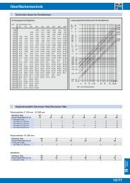
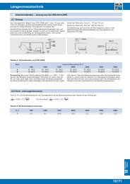
Rules - extract from the DIN standard 874flat steel rule up to 1500 mm lengthtest surfacelateral surfaceflat steel rule from 2000 mm length(except precisions grade 2)test surfacetest surfacelateral surfacetest surface2.1.1 Flatness toleranceThe flatness tolerances t e of the test surfaces are determined using theformula in accordance with Table 2. The length is entered l in mm.Table 2. Formulae for flatness tolerances of the test surfacesPrecision grade0000102 +20 8 +2.1.2 Parallelism toleranceFlatness tolerancet e in µml100l40The parallelism tolerance of the test surfaces is equal to double thecorresponding flatness tolerance. The parallelism tolerance of thelateral surfaces is six times the flatness tolerance of the measurementsurfaces specified in Table 3. The tolerances in Table 3 are therounded up tolerances determined using the formula in Table 2.1 +4 +l150l602.5 DesignThe test surfaces of the flat steel rules, precision grade 2, are usuallyfine ground. The test surfaces on flat rules made of steel, precisiongrades 00 and 0, are additionally scraped or lapped. Those in precisiongrade 1 are additionally scraped if the tolerances cannot be obtainedthrough fine grinding.3. Testing3.1 <strong>Measuring</strong> the deviation from flatnessThe deviation from flatness is measured against a reference surfacewhose own deviation from flatness is less than 50 % of the flatnesstolerances specified in Table 3.The rule being tested is supported at those points at which the slightestbending of the rule occurs. Where there is a constant crosssection,these supporting points are spaced as shown in Figure 2.The deviation from flatness can be measured e.g. with gauge blocksin accordance with DIN 861 sheet 1 and/or test mandrels betweenthe reference plane and the facing test surface of the flat steel rule.When testing on fold the measuring results are not subject tointerference from bending.Table 3. Flatness tolerancesl Flatness tolerance t e in µmat precision grades±2 00 0 1 2up to 500 4 7 12 21750 6 9.5 17 271000 8 12 21 331500 – 17 29 462000 – 22 37 582500 – 27 46 713000 – 32 54 834000 – 42 71 1085000 – – 87 133These values apply at a reference temperature of 20° C.The flatness tolerance of the lateral surfaces is equal to three timesthe flatness tolerances of the test surfaces specified in Table 3.Figure 2. Support at points of slightest bending3.2 <strong>Measuring</strong> the deviation from parallelismThe deviation from parallelism can be determined in the same testset-up as in Section 3.1 with the aid of a DIN 879 dial gauge on theupper test surface of the flat steel rule.Flat steel rules can also be tested with measuring instruments whosemax. error = 20 % of the parallelism tolerance of the rules, e.g. micrometerwith dial gauge or external micrometer.