


Precision Farming System PF3000 Operators Manual
Precision Farming System PF3000 Operators Manual
Precision Farming System PF3000 Operators Manual

You also want an ePaper? Increase the reach of your titles
YUMPU automatically turns print PDFs into web optimized ePapers that Google loves.
<strong>PF3000</strong>Ag Leader TechnologyGeneralWelcomeWelcome to the Ag Leader Technology family. Ag Leader Technology isdedicated to the development of advanced, yet practical and cost-effectivetools for grain production. Above all, however, we are dedicated to meetingyour needs for support of existing products and development of productimprovements.We want to hear from you! Feel free to call any time to discuss:• Operational problems with your system• Features you don’t like about your system• Features you would like added to your systemWe will do our best to ensure that you are happy with your current systemand that it is upgraded in the future to better meet your needs.<strong>System</strong> UpgradesAg Leader Technology will periodically provide free operating programupgrades that will improve the performance of your <strong>PF3000</strong>.To receive free upgrades and new product news, you must send in or fax(515-232-3595) the Registration Form that is at the beginning of theoperator’s manual. Our mailing address is:Ag Leader Technology2202 South Riverside DriveP.O. Box 2348Ames, IA 50010Internet http://www.agleader.comLimited WarrantyAg Leader Technology will repair or replace at no charge any component ofthe <strong>PF3000</strong> system that fails during normal service on the equipment modelthat the system was intended for use within two years from the date of firstuse.Warranty is not provided for damage resulting from abuse, neglect,accidents, vandalism, acts of nature, or any other causes that are outside thenormal, intended use of the <strong>PF3000</strong> system.February 1999 1-1
General<strong>PF3000</strong>Ag Leader TechnologyAg Leader Technology shall not be liable for indirect, incidental, orconsequential damages to the dealer, end user, or third parties arising fromthe sale, installation, or use of the <strong>PF3000</strong> system.ServiceIf you have a problem with your system, call your Ag Leader Technologydealer or call us directly at the phone number below. If we determine youhave a hardware failure, we will ship replacement hardware immediately.Our mailing address and phone numbers are:Ag Leader Technology2202 South Riverside DriveP.O. Box 2348Ames, IA 50010Phone: 515-232-5363Fax: 515-232-3595Note: Return failed hardware to us by UPS (preferred) or US mail.Copyright NoticeAg Leader Technology has copyrighted (©1998) the contents of this manualand the operating program for the <strong>PF3000</strong> system. No reproductions of thismaterial may be made without first obtaining the consent of Ag LeaderTechnology.ProprietaryTechnology NoticeThe <strong>PF3000</strong> system has patents on its design and operational features.Copying features of this system relating to measurement and calculation ofgrain flow and weight, or organization of field and load data may result inpatent infringement.1-2February 1999
<strong>PF3000</strong>Ag Leader TechnologyGeneralGeneralDescriptionThe <strong>PF3000</strong> is a universal monitor/controller for crop production that isGPS compatible. It can be transferred from a combine to a tractor or othervehicle easily. In the combine it functions as a yield monitor and accuratelymeasures and records acres, moisture, grain weight, bushels, and yield onthe-go.In the tractor or sprayer it connects to a sprayer or planter controllerand monitors and controls the application rate. The <strong>PF3000</strong> also can recorddata for field boundaries, tile lines or where a hybrid is planted.The <strong>PF3000</strong> has its own internal memory for recording field and load data.GPS data, however, is not recorded in the internal memory, but mustbe logged to a memory card.The <strong>PF3000</strong> must be setup and calibrated to record accurate information.Fields and LoadsAll the information recorded by the <strong>PF3000</strong> must be recorded in a field andload. The operator must manually select or change the field and load on the<strong>PF3000</strong> during field operation. A load is used to subdivide a field intosmaller sections. The monitor load is not associated with the combine tank,wagon, or truck load. It is recommended to use different loads for differenthybrids or varieties or field conditions (like a wet hole).KeypadThe monitor has “soft” keys which do not have labels on the keys to identifythe function of the key. The labels for the keys will appear on the displayscreen next to the key. However, there are four major groups of the keys:arrow keys, display selection keys, menu key, menu selection keys.February 1999 1-3
General<strong>PF3000</strong>Ag Leader TechnologyDisplaySelectionKeysMemoryCard SlotPowerSwitchArrowKeysMenuKeyAreaCountSwitchMenuSelectionKeysFigure 1: Front panel of the <strong>PF3000</strong>Arrow KeysThe UP, DOWN, LEFT and RIGHT ARROW keys on the right side of thekeypad are used to select and change a setting. The bottom LEFT andRIGHT ARROW keys are only used to view more menu or display items.They are never used to select or change a setting.On the main operating screen, you will see an up and down arrow symbolthat will either be beside the field or load or to the right of one of the displaylines. This symbol indicates what item the UP or DOWN ARROW keys willchange if pressed.1-4February 1999
<strong>PF3000</strong>Ag Leader TechnologyGeneralDisplay andDisplay SelectionKeysThe <strong>PF3000</strong> has four display lines for viewing items on the main operatingscreen. You can choose which items you see on the display and the positionthat the items appear on the display.To change a display item on a display line you must select the line. The fourdisplay selection keys to the right of the display each select a display line. Arectangular box surrounds the display line to show that it is selected.When the display line is selected the four menu items on the bottom changeand show items you can select for display. Press a key below one of the fourdisplay items to put a different display item in place of the selected displayitem. There are more than four display items to choose for viewing. Pressthe bottom LEFT or RIGHT ARROW keys to scroll to the right or left andview other display items on the bottom.CardSymbolSelectionBoxUp andDownArrowSymbolWhen arrows present,press bottom arrow keysto display additional menuor display itemsFigure 2: Main operating screenWhen some display items (like swath) are selected, an up and down arrowFebruary 1999 1-5
General<strong>PF3000</strong>Ag Leader Technologysymbol will appear on the right of the display line. This indicates you canchange the setting of the item with the UP or DOWN ARROW keys. Afteryou have made the change you must press the key to the right of the displayline to deselect the line.Menu KeyThe MENU key switches the menus on the bottom of the display. There aretwo main menus that you can view by pressing the MENU key. They areshown below.It is recommended to display the FIELD, LOAD, MAP, and MARKS menuduring normal operation of the monitor, unless you are marking andtherefore need to display marks on the bottom.Main Menus:FIELD LOAD SHOWMAPOPTIONSSUMMARY CAL SETUP DIAGMenu SelectionKeysThe name above the four menu selection keys on the bottom of the displaywill change depending on what you are doing on the monitor.The bottom RIGHT and LEFT ARROW keys are used to view additionalmenu or display items. If you see a right and left arrow symbol on thedisplay above the bottom RIGHT and LEFT ARROW keys, this indicatesyou can press the bottom RIGHT and LEFT ARROW keys to view moremenu or display items. Refer to Figure 2.1-6February 1999
<strong>PF3000</strong>Ag Leader TechnologyGeneralArea Count SwitchThe area count switch manually turns on and off area counting. When theswitch is in the up position area is counting. When the switch is in the downposition, area is not counting. The monitor will display either “AREA ON”or “AREA OFF” on the bottom right corner of the display to indicate thestatus of area couting.ConnectorsThe <strong>PF3000</strong> has four connectors on the bottom side of the console. Thelarge 25-pin connector is for power and sensor connections. The three 9-pinports (Port 1, Port 2, Port 3) are for connecting to a GPS receiver, planteror fertilizer or sprayer controller or any other GPS compatible device.February 1999 1-7
General<strong>PF3000</strong>Ag Leader TechnologyGrain Flow SensorBelow is an example of a grain flow sensor. Your grain flow sensor maylook different, depending on which combine model you have. On allcombines, the grain flow sensor installs on top of the clean grain elevator.The grain flow sensor measures the grain weight in pounds as you harvest.The clean grain paddles throw the grain, as the paddles rotate around the topsprocket, toward the grain flow sensor. The flow sensor measures the grainweight when the grain strikes the flow sensor impact plate.Grain FlowSensorFigure 3: Grain flow sensor1-8February 1999
<strong>PF3000</strong>Ag Leader TechnologyGeneralMoisture SensorBelow is an example of the moisture sensor mounted on the side of a cleangrain elevator. The moisture sensor is installed in the elevator mount kit.Moisture SensorElevatorMount KitFigure 4: Moisture sensorFebruary 1999 1-9
General<strong>PF3000</strong>Ag Leader TechnologyHeader HeightSensorBelow is an example of a header height sensor installed underneath acombine cab. The header height sensor tells the monitor the position of thecombine head so that when the head is raised on the end rows, the monitorstops counting area.Header SensorFigure 5: Header height sensor* * *1-10February 1999
<strong>PF3000</strong>Ag Leader TechnologySetup OverviewImportant NoticesThe <strong>PF3000</strong> must be set up before field operation, but before you begin thesetup procedures, read the following notices:• The <strong>PF3000</strong> is a software upgradeable monitor. Ag Leader Technologywill periodically offer free operating program upgrades to increase thecapabilities of the <strong>PF3000</strong>. To receive the program upgrade, youmust send in the registration form found at the beginning of theoperator’s manual.• If you plan to make yield maps on your own computer, you will need touse <strong>Precision</strong> Map 2000 (or another mapping program that can processmemory cards from the <strong>PF3000</strong>) to process the memory cards when theyget full. <strong>Precision</strong> Map 2000 and memory cards can be ordered throughyour Ag Leader Technology dealer.Section ContentsThis setup section contains instructions for the following items. Theoperating modes that the instructions pertain to are also listed.Item Operating Mode PageConsole Setup All 2-4Card Setup All 2-6Creating, Naming Fields and Loads All 2-10Marker Setup All 2-15Vehicle Setup Harvest 2-17Grain Setup Harvest 2-22Swath Setup Harvest 2-27Swath Setup Application Rate 2-29Vehicle Setup Application Rate 2-30Application Rate Setup Application Rate 2-31Controller Setup Application Rate 2-36Product Setup Application Rate 2-48Swath Setup Site Verification 2-58Vehicle Setup Site Verification 2-59Using PowerSupplyThe <strong>PF3000</strong> console does not need to be in the vehicle to set it up. You canuse the provided power supply (plugs into 120v outlet) to power up theconsole inside your home or shop.February 1999 2-1
Setup Overview(All Modes)<strong>PF3000</strong>Ag Leader TechnologyOrder of Keys(Harvest Mode)Press the MENU keythe display.until you see the following keys onSUMMARY CAL SETUP DIAGPress the SETUP key to view thefollowing setup menu items.SWATH MARKS GRAIN CARDLOAD VEHICLE CONSOLE MEMORYGPSPress the bottom LEFT or RIGHT ARROW keys toswitch between and view the setup menu itemsshown above.Order of Keys(Site VerificationMode)Press MENU keythe display.Until you see the following keys on theCAL SETUP DIAGPress the SETUP key to viewthe following setup menu items.SWATH MARKS CARD LOADVEHICLE CONSOLE MEMORY GPSPress the bottom LEFT or RIGHT ARROW keys toswitch between and view the setup menu itemsshown above.2-2February 1999
<strong>PF3000</strong>Ag Leader TechnologySetup Overview(All Modes)Order of Keys(Application RateMode)Press the MENU keythe display.until you see on the following keys onSUMMARY CAL SETUP DIAGPress the SETUP key to view thefollowing setup menu items.SWATH APP. RATE CONTRLER PRODUCTMARKS CARD LOAD VEHICLECONSOLE MEMORY GPSPress the bottom LEFT or RIGHT ARROW keys toswitch between and view the setup menu itemsshown above.* * *February 1999 2-3
Console Setup(All Modes)<strong>PF3000</strong>Ag Leader TechnologyIntroductionThe console settings are general settings that apply to all operating modesand uses of the <strong>PF3000</strong>.Console SetupScreenTo view the console setup screen press the:MENU keySETUP keybottom RIGHT ARROW keyCONSOLE keyExample of console setup screen:CONSOLE SETUPOperating ModeGRAIN HARVESTMonth/Day/Year 08/15/1998Time1:15 PMSerial Number 980034Box Cal 770Voltage Cal 490GPS Check SumONField Marker InputINTERNALEDITEXITACCEPTCANCELChanging a Setting Step Action1 Use the UP or DOWN ARROW keys to select the item you wantto change. The item is selected when a black filled rectangular boxsurrounds the entire line.2 Press the EDIT key and then use the UP or DOWN ARROW keysto change the number or setting.3 Once you have changed a setting press the ACCEPT key. Pressthe EXIT key once you have made all the settings.2-4February 1999
<strong>PF3000</strong>Ag Leader TechnologyConsole Setup(All Modes)Operating modeThere are three main operating modes of the <strong>PF3000</strong>.• Grain Harvest Mode• Application Rate Mode• Site Verification ModeIf you are...Harvesting and you want to do yield monitoringPlanting, spraying, or fertilizing and you want torecord or control your application rate for mappingpurposesPlanting, spraying, or fertilizing and you want to mapwhere you apply a product or if you want to log yourfield boundary or tile linesSelectGRAIN HARVESTAPPLICATIONRATESITEVERIFICATIONOnce you have changed the operating mode and you hit the EXIT key toexit the console setup screen, the <strong>PF3000</strong> will begin operating in the newoperating mode. Upon changing the operating mode you should make sureall the setup items for that operating mode are correct.Serial number,Box calibration,Voltage calibrationGPS Check SumThe serial number, box calibration number and voltage calibration numbercan be found on the bottom side of the monitor. These numbers should beset correctly from the factory.If you are using a GPS receiver with the <strong>PF3000</strong> the GPS Check Sum settingis used to enable or disable data string error checking.NOTE: For all Ag Leader receivers (GPS 2000/2100, Add-on GPS3000/3100), and Trimble 120,122,132 receivers the GPS Check Sum shouldbe set to ON.For most other brands of GPS receivers the GPS Check Sum should also beset to ON. If you can not get a “D” and “G”, though, set this setting to OFF.Field Marker If you are... SelectMarking field points with the <strong>PF3000</strong>’s internalINTERNALmarker selection keys.Marking field points with an external Ag LeaderField Marker.EXTERNAL* * *February 1999 2-5
Card Setup(All Modes)Introduction<strong>PF3000</strong>Ag Leader TechnologyIf you are using a GPS receiver, all the GPS data must be logged to amemory card. If you are not using a GPS receiver, you do not need a card.The memory card must be formatted with a DOS format. Cards rarely needto be formatted since they are usually DOS formatted before they areshipped. If formatting is required, format the card in your PC before using.IMPORTANT:You must copy memory to every log file you create and log to beforeyou read the card into your computer.Card Setup ScreenTo view the card setup screen press the:MENU keySETUP keyCARD keyExample of card setup screens:CARD SETUPLogging DeviceLogging IntervalLog fileMEMORY CARD1 second98081501.YLDCOPY TO SHOW ALLEDIT CARD FILES EXITACCEPTCANCELFILES ON CARDFILE NAME SIZE LAST MODIFIED98081502.YLD 130 KB 08/15/199898081501.YLD 128 KB 08/15/199898073001.YLD 130 KB 07/30/1998FILEERASEOPTIONS ALL EXIT2-6February 1999
<strong>PF3000</strong>Ag Leader TechnologyCard Setup(All Modes)FILES OPTIONSFile Name98081501.YLDFile Size132640 bytesLast Modified 13:42Date 08/15/1998COPY TO RESTORE ERASEFILE FILE FILE EXITChanging a Setting Step Action1 Use the UP or DOWN ARROW keys to select the item you wantto change. The item is selected when a black filled rectangular boxsurrounds the entire line.2 Press the EDIT key and then use the UP or DOWN ARROW keysto change the number or setting.3 Once you have changed a setting press the ACCEPT key. Pressthe EXIT key once you have made all the settings.Logging DeviceIf you are using a GPS receiver with the <strong>PF3000</strong> you must use a memorycard to save the instantaneous GPS data.If you...SelectDo not have a GPS receiver.NONEDo have a GPS receiver.MEMORY CARDNOTE: In Application Rate mode, if the <strong>PF3000</strong> is controlling applicationrate, but you don’t want to log actual rate to card set to NONE.Logging IntervalThis setting determines how often the GPS information is saved to thememory card. It also affects how large an area each GPS record willrepresent on a map and how many logging hours are available before thememory card becomes full.There are three possible settings for the logging interval.1, 2 or 3 Seconds. The recommended setting is either two or three seconds.Distance Traveled (ft)1 sec 2 sec 3 sec3 mph 4.4 8.8 13.25 mph 7.3 14.6 21.9February 1999 2-7
Card Setup(All Modes)<strong>PF3000</strong>Ag Leader TechnologyLogging Hours Available/Logging Interval1 sec 2 sec 3 sec1 M Card 15.7 31.5 47.32 M Card 33.8 67.6 101.4SANDISK 20 M ATA 250 500 750Flash CardNOTE: The logging hours available can vary from the numbers shown abovedue to the number of separate files that can be stored on the card.Log FileThe <strong>PF3000</strong> requires a log file to store data on a memory card. The log filewill always have a “.yld” extension and be named with the date the file wascreated. Example: 98081502.yld, second file created on 08/15/98.IMPORTANT: You must copy memory to every log file you create andlog to before you read the card into your computer. Every time you turnoff the monitor you will be prompted to copy memory to a card (thiscopies memory only to the file set as the log file). If you have created andlogged to more than one log file, before you read the card, you should atthe card setup screen, copy memory to file on every log file.The criteria for logging to log files differs based on the type of card.Type of CardLog file criteriaSRAM card A new log file does not have to be created for each day.Can add to any old log file repeatedly after a new file hasbeen created. Can store one log file on a card.SANDISK ATAFLASH cardA new log file must be created for each day. Can not addto an old log file after a new file has been created. Canstore multiple log files on one card.In order to log instantaneous GPS data or copy field and load data to amemory card, a log file must be selected. Every time you turn on the monitor,the monitor will prompt you to select or create a log file. Refer to the stepsbelow to select or create a log file after the monitor has been turned on.StepAction1 Select Log File and press the EDIT key.2 Select a log file or press CREATE FILE key to create a new log file.3 With the desired file selected, press the ACCEPT key.NOTE: After you read all the log files on your card into your computer (andmake backup copies of files), it is recommended to erase the log file(s) on thecard.2-8February 1999
<strong>PF3000</strong>Ag Leader TechnologyCard Setup(All Modes)Copying Data toLog FileIMPORTANT:Before you remove the memory card from the monitor, you must copymemory to every log file that you have logged to, otherwise your datacould be lost. Every time you turn off the monitor you will be promptedto copy memory to a card (this copies memory only to the file set as thelog file).To copy memory to log files that are not set as the current log file, press theSHOW FILES key and select one of the log files. Press the FILE OPTIONSkey and press the COPY TO FILE key. At the card setup screen, press theCOPY TO CARD key to copy memory to the file set as the log file (this is thesame copy to card function that you are prompted to do during shut down).Restoring fromFileYou can restore field and load data into the monitor’s memory from a log fileon a memory card..IMPORTANT: It is dangerous to restore memory from a card becausethe current data in the monitor will be replaced with the data on card.StepAction1 Press the SHOW ALL FILES key. Select the log file and press theFILE OPTIONS key. Press the RESTORE FILE key.2 Press the RESTORE key again if you really want to restore the data.3 Press the EXIT key once you are finished.Erasing FileYou can erase individual log files from a memory cardStepAction1 Press the SHOW ALL FILES key. Select the log file and press theFILE OPTIONS key. Press ERASE FILE key.2 Press the ERASE key again if you really want to erase the file.3 Press the EXIT key once you are finished.* * *February 1999 2-9
Creating, Naming Fields, Loads(All Modes)<strong>PF3000</strong>Ag Leader TechnologyRecommendationsAll the information recorded by the <strong>PF3000</strong> must be recorded in a field andload. The field and load that the monitor is set on is located on the top lineof the display on the main operating screen.FieldsYou should at least create all the fields and name them before you begin touse the <strong>PF3000</strong>. The monitor will use the same set of fields you create foreach operating mode (harvest mode, application rate mode, site verification)of the monitor. You can create and name your fields using any operatingmode. You should choose field names that you can use year after year.LoadsIt also recommended to create and name loads within fields before you usethe <strong>PF3000</strong>. Each operating mode of the <strong>PF3000</strong> will have its own set ofloads for each field.Definition:Load: A load is used to subdivide a field into smaller sections. The monitorload is not associated with the combine tank, wagon, or truck load.LoadField2-10February 1999
<strong>PF3000</strong>Ag Leader TechnologyCreating, Naming Fields, Loads(All Modes)Creating and Step ActionNaming Fields 1Press the MENU keyuntil the following is displayed onthe bottom of the display.FIELD LOAD SHOWMAPOPTIONS2 Press the FIELD key twice to view the screen below.F1: DGACTIVE FIELDF1: PRESS TO EDIT NAMESELECT GRAINSOYBEANSACCEPTCANCELStepAction3 Naming FieldWith the line displaying the field number selected (rectangular boxsurrounds line), press the RIGHT ARROW key to move the cursor tothe right to enter a name. Use the UP or DOWN ARROW keys to scrollthrough letters, numbers and other characters. After you have set thecharacter, move the cursor to the right by pressing the RIGHT ARROWkey and set a new character. You can enter up to an 8-character name.Press the ACCEPT key once you have entered a name.4 Setting Grain (harvest mode), Product (application rate mode), orSite Type (Site Verification Mode)To set the grain, product or site type for the field you must select the linedisplaying the grain, product or site type. Press the key to the right ofthe line displaying the grain, product or sit type to select the line. Usethe UP or DOWN ARROW keys to set the setting. Press the ACCEPTkey twice, once to accept the grain, product or site type, once to acceptthe field.StepActionFebruary 1999 2-11
Creating, Naming Fields, Loads(All Modes)<strong>PF3000</strong>Ag Leader Technology5 Creating FieldsPress the UP ARROW key to scroll through all the fields. Once youscroll past the last field, “Create New Field” will be displayed. Namethe field and set the grain, product or site type, then with “Create NewField” displayed above the field number press the ACCEPT key tocreate the new field.6 Repeat Step 5 and create and name all your fields.NOTE: You can have more than one grain, product or site type in a field.To enter more than one grain, product, or site type, press the FIELD key twiceso that the field is displayed in large text. Select the line displaying grain,product or site type and change the setting. Press the ACCEPT key twice,once to accept the new grain, product or site type and once to accept the field.The monitor will create a separate set of loads (which are renumberedbeginning with load one) for each grain, product or site type in a field.Example of load organization when two grain types are in one field inharvest mode:CornSoybeansF10 L1 F10 L1L2L2L3L3L4L4Harvest grain types Application product types Site Verification typesSOYBEANSCORN1 PLANTING 1CORNCORN2 PLANTING 2WHEATBEANS1 PLANTING 3OATSBEANS2 SPRAYING 1RYEBEANS3 SPRAYING 2BARLEYBEANS4 SPRAYING 3SORGHUMBEANS5 FERTILIZER 1POPCORNBEANS6 FERTILIZER 2EDIBL BEANS BEANS7 FERTILIZER 3CORN 2SPRAY1 OPT SITE 1CANOLASPRAY2 OPT SITE 2RICEFERT1 OPT SITE 3SUNFLOWERS FERT2 OPT SITE 4CORN 3APP RATE1 OPT SITE 5CORN 4APP RATE2 OPT SITE 6OPT GRAIN 1 APP RATE3 OPT SITE 72-12February 1999
<strong>PF3000</strong>Ag Leader TechnologyCreating, Naming Fields, Loads(All Modes)Creating and Step ActionNaming Loads 1Press the MENU keyuntil the following is displayed onthe bottom of the display.FIELD LOAD SHOWMAP2 Press the LOAD key twice to view the screen below.OPTIONSF1: L1: DGACTIVE LOADL1: PRESS TO EDIT NAMESELECT GRAINSOYBEANSACCEPTCANCELStepAction3 Naming LoadWith the line displaying the load number selected (rectangular boxsurrounds line), press the RIGHT ARROW key to move the cursor tothe right to enter a name. Use the UP or DOWN ARROW keys toscroll through letters, numbers and other characters. After you haveset the character, move the cursor to the right by pressing the RIGHTARROW key and set a new character. You can enter up to an 8-character name. Press the ACCEPT key once you have entered aname.February 1999 2-13
Creating, Naming Fields, Loads(All Modes)<strong>PF3000</strong>Ag Leader TechnologyStepAction4 Creating LoadsPress the UP ARROW key to scroll through all the loads in the fieldfor the grain type. Once you scroll past the last load, “Create NewLoad” will be displayed above the load number and name. Name theload and set the grain type, then with “Create New Load” displayedabove the load number press the ACCEPT key to create the newload.5 Repeat step 4 and create and name all your loads.Note: Refer to Load Setup to change grain, product or site type for anexisting load.Changing Fieldsand LoadsChanging FieldPress the FIELD key to display current field. Press the UP or DOWNARROW keys to scroll through the fields. Press the ACCEPT key tochange to the different field.NOTE: If you are in the application rate operating mode and youhave application control set to on under the APP. RATE setup key,the monitor will ask you to select a target rate file for the differentfield.Changing LoadPress the LOAD key to display the current load. Press the UP or DOWNARROW keys to scroll through the loads. Press the ACCEPT key tochange to the different load.* * *2-14February 1999
<strong>PF3000</strong>Ag Leader TechnologyMarker Setup(All Modes)IntroductionIf you are using an external Field Marker ignore the instructions below. Themarker setup screen is only used for making settings for the Internal markerselection keys.IMPORTANT:If you are using the external field marker, make sure that under theCONSOLE key you set Field Marker to EXTERNAL.Marker SetupScreenTo view the marker setup screen press the:Example of marker setup screen:MENU keySETUP keyOPTIONS keyMARKS keyMARKER SETUPMARK NAME TYPEMARK 1 WEEDS CONTINUOUSMARK 2 ROCKS SPOTMARK 3 TILE CONTINUOUSMARK 4 WET SPOT SPOTEDITEDITNAME TYPE EXITACCEPTCANCELFebruary 1999 2-15
Marker Setup(All Modes)<strong>PF3000</strong>Ag Leader TechnologyChanging a Setting Step Action1 Use the UP or DOWN ARROW keys to select the mark. Themark is selected when a black filled rectangular box surrounds theentire line.2 Press the EDIT NAME key to rename an existing mark. Use theUP or DOWN ARROW keys to change a character in the name.Use the LEFT or RIGHT ARROW keys to move the cursor overanother character within the name. Press the ACCEPT key afteryou have changed the name.3 Press the EDIT TYPE key to set the mark for continuous or spotmarking. Use the UP or DOWN ARROW keys to change thesetting. Press the ACCEPT key after you have changed the setting.4 Press the EXIT key once you have made all the settings.Continuous markingSet the marking type to continuous if the item in the field you are markingrequires you to make several marks in a row (for example: marking largeweed patches or tile lines).When you press a mark key that is set for continuous marking, the mark willremain on until you press the mark key again to turn off the mark.Spot markingSet the marking type to spot if the item in the field you are marking requiresjust one mark (for example: marking a rock or tile hole).When you press a mark key that is set for spot marking, the mark will remainon only for a few seconds and then will automatically go off.* * *2-16February 1999
<strong>PF3000</strong>Ag Leader TechnologyVehicle Setup(Harvest Mode)IntroductionFor each operating mode, there are different items to setup in the vehiclesetting screen. Below are the setup items for the harvest mode. Refer toyour Initial Calibration Sheet to make the correct settings.Vehicle SetupScreenTo view the vehicle setup screen press the:MENU keySETUP keybottom RIGHT ARROW keyVEHICLE keyExample of vehicle setup screen:VEHICLE SETUPElevator pulses / revolution1 PulsesSprocket teeth8 TeethCombine scale factor 1.0Area count stop beeps20 BeepsExpand grain below dry %NOSensor calibration 1400T1 10T2 5T3 8Primary speed sensorWHEELSSecondary speed sensor ---------Speed sensor pulses / 100 ft2000 PulsesEDITEXITACCEPTCANCELFebruary 1999 2-17
Vehicle Setup(Harvest Modes)<strong>PF3000</strong>Ag Leader TechnologyChanging a Setting Step Action1 Use the UP or DOWN ARROW keys to select the item you wantto change. The item is selected when a black filled rectangular boxsurrounds the entire line.2 Press the EDIT key and then use the UP or DOWN ARROW keysto change the number or setting.3 Once you have changed a setting press the ACCEPT key. Pressthe EXIT key once you have made all the settings.Elevatorpulses/revolutionSprocket teethCombine scalefactorRefer to the Initial Calibration Sheet for the correct setting for yourcombine.Refer to the Initial Calibration Sheet for the correct setting for yourcombine.Refer to the Initial Calibration Sheet for the correct setting for yourcombine.IMPORTANT:• Never change the scale factor during harvest. Doing so will causethe monitor to lose calibration accuracy and you will have to set themonitor on different grain types and recalibrate every grain type.• All of your calibration loads and data loads must be harvested usingthe same scale factor setting otherwise you will have severecalibration problems that possibly can not be corrected.2-18February 1999
<strong>PF3000</strong>Ag Leader TechnologyVehicle Setup(Harvest Mode)Area count stopbeepsThis setting is for the number of times the monitor beeps when the head israised at the end of a pass and the monitor stops counting area.NOTE: The recommended setting is 20. Set this number high enough sothat after the head is raised at the end of a pass, the beeps continue untilthe combine is completely turned around and the head is lowered to startthe new pass. This gives the operator an audible signal that the head islowered enough to begin counting area again.Expand grain below If you select . . . Then . . .Dry % No, You prevent the monitor from adding bushels to grainthat is dryer than the dry percent moisture by which drybushels are calculated. This calculates all yields in termsof actual bushels available for you to sell.(Recommended setting).Yes,The monitor shows a yield comparison of all loads at thedry percent moisture. This increases the bushels of thegrain harvested below the dry percent moisture toaccount for moisture lost because of excessive dryness ofthe grain.NOTE: This setting applies to all loads and grains in the monitor. It can bechanged from NO to YES and vice-versa at any time.Sensor calibrationRefer to the Initial Calibration Sheet for the correct setting for yourcombine.NOTE: If you replace the flow sensor, you must change this setting to thevalue of the new sensor calibration number of the new flow sensor.T1, T2, T3 Refer to the Initial Calibration Sheet for the correct setting for yourcombine.February 1999 2-19
Vehicle Setup(Harvest Mode)<strong>PF3000</strong>Ag Leader TechnologyPrimary andSecondary speedsensorThe monitor has four different primary speed settings. They are listedbelow.Ground Speed SensorSpeed sensor on transmissionSpeed sensor on tracksRadar gunGPS receiver (must be rated for accurateground speed: GPS2000/2100, Add-OnGPS3000/3100 and Trimble AgGPS receivers)Primary Speed SensorWHEELTRACKRADARGPSIf you choose GPS as your primary speed sensor, you need to set thesecondary speed sensor to WHEEL, TRACK, or RADAR. If the GPSsignal is lost, the monitor will use the secondary speed sensor. If you do notchoose GPS as your primary speed sensor you can not set the secondaryspeed sensor.2-20February 1999
<strong>PF3000</strong>Ag Leader TechnologyVehicle Setup(Harvest Mode)Speed sensor pulses/ 100 ft.It is not recommended that you change this setting. This number is thedistance calibration number that is set when you perform a distancecalibration for WHEEL, TRACK or RADAR. Refer to the calibratingdistance instructions in the Calibration section. You must calibrate distancefor a WHEEL, TRACK or RADAR setting for accurate ground speed.NOTE: If you want to use a radar gun, contact an Ag Leader Technologydealer and purchase a special adapter cable for your radar gun.* * *February 1999 2-21
Grain Setup(Harvest Modes)<strong>PF3000</strong>Ag Leader TechnologyGrain SetupScreenTo view the grain setup screen press the:MENU keySETUP keyGRAIN keyExample of grain setup screen:GRAIN SETUPGRAIN NAME TYPEGRAIN 1 SOYBEANS Low FlowGRAIN 2 CORN Hi FlowGRAIN 3 WHEAT Low FlowGRAIN 4 OATS Low FlowEDITEDITNAME SETTINGS EXITACCEPTCANCEL2-22February 1999
<strong>PF3000</strong>Ag Leader TechnologyGrain Setup(Harvest Mode)Changing a Setting Step Action1 Use the UP or DOWN ARROW keys to select the grain. Thegrain is selected when a black filled rectangular box surrounds theentire line.2 Press the EDIT SETTINGS key to move to another screen andchange the settings for the selected grain. Refer to the screenbelow.3 Press the EDIT NAME key to rename an existing grain (can notrename SOYBEANS, CORN, or WHEAT). Use the UP orDOWN ARROW keys to change a character in the name. Use theLEFT or RIGHT ARROW keys to move the cursor over anothercharacter within the name. Once you have changed the grain namepress the ACCEPT key.4 Press the EXIT key once you have made all the settings.Example of grain settings screen:GRAIN SETTINGS: CORNDry lbs / bu56 lb / buDry moisture 13.0 %Moisture offset 4.7 %Stop height 54M1 400S1 50EDITEXITACCEPTCANCELFebruary 1999 2-23
Grain Setup(Harvest Mode)<strong>PF3000</strong>Ag Leader TechnologyDry lbs / buDry moistureThis setting is the pounds / bushel value that the monitor uses to calculatebushels. You can change this setting for all grains except corn (56 lbs / bu),soybeans (60 lbs / bu) and wheat (60 lbs / bu).This setting is the moisture value that the monitor uses to calculate drybushels.Example:Corn – 15%Soybeans – 13%Moisture offsetStop HeightM1S1Refer to the Initial Calibration Sheet for the correct setting. Do not readjustthe moisture offset number after you have performed a moisture calibration.This setting determines how high the combine head must be raised to makethe monitor stop counting area. This number can be automatically set underthe CAL, STOP HGT key.Refer to the Initial Calibration Sheet for the correct setting.Refer to the Initial Calibration Sheet for the correct setting.Setting Initial CNumbersThe 11 C Numbers, C1 through C11 determine the pounds of grain that themonitor calculates. The C numbers initially should be set to the same valuesthat appear on your Initial Calibration Sheet, but they will change andbecome more accurate after you have calibrated.Do not change the C numbers after you have calibrated.You only need to set the C11 number to its initial value. When you set theC11 number, the C2-C10 numbers will automatically change to the correctvalue. Do not set the C1 number. It is adjusted automatically when you doa vibration calibration.2-24February 1999
Grain Setup(Harvest Mode)<strong>PF3000</strong>Ag Leader TechnologyGRAIN CALIBRATIONSELECT GRAIN:SOYBEANSENTERWEIGHTSHOW CALLOADSSHOW CALNUMBERSEXITGRAIN CALIBRATION: SOYBEANSCALIBRATION NUMBERSC1 0C2 250C3 500C4 750C5 1000C6 1250C7 1500C8 1750C9 2000C10 2250C11 2500EDITCALON/OFFPERFORMCALEXITACCEPTCANCEL* * *2-26February 1999
<strong>PF3000</strong>Ag Leader TechnologySwath Setup(Harvest Mode)IntroductionThe swath setup screen is used to set the permanent, full swath of your head.Do not adjust the swath setting on this screen when you encounter a partialswath while harvesting. Refer to the Swath Setting instructions in OperationSection and select swath as a display item and set a partial swath.Swath SetupScreenTo view the swath setup screen press the:Example of swath setup screen:MENU keySETUP keySWATH keySWATH SETUPGRAIN # ROWS SPACING FULL SWATHSOYBEANS 24 12 in 24 ft 0 inCORN 8 30 in 20 ft 0 inWHEAT 24 12 in 24 ft 0 inOATS 24 12 in 24 ft 0 inEDITEDIT# ROWS SPACING EXITACCEPTCANCELFebruary 1999 2-27
Swath Setup(Harvest Mode)<strong>PF3000</strong>Ag Leader TechnologyChanging a Setting Step Action1 Use the UP or DOWN ARROW keys to select the grain. Thegrain is selected when a black filled rectangular box surrounds theentire line.2 Press the EDIT # ROWS key to change the number of rows. Usethe UP or DOWN ARROW keys to change the number. Press theACCEPT key after you have changed the number.3 Press the EDIT SPACING key to change the row spacing. Use theUP or DOWN ARROW keys to change the number. Press theACCEPT key after you have changed the number.4 Press the EXIT key once you have made all the settings.Recommendations for Row Crop Heads:• For row crops, set your row space to the planted row spacing and yournumber of rows to the number of total rows of your combine head.Recommendations for Cutting Platform Heads:Row Crops• For row crops, set your row space to the planted row spacing and yournumber of rows to the number of total rows your cutting platform willcut.Non-rowed crops• Set the swath in the monitor to one foot less than the actual swath widthof the head because you can rarely maintain a constant full swath whileharvesting.Example: If your cutting platform head is 20 actual feet, set themonitor’s swath to 19 feet by setting the row space to 12 inches and thenumber of rows to 19.• Set the monitor on a row space of 12 inches and a number of rows thatadds up to the correct swath. Setting the row space to 12 inches forcutting platforms allows you to reduce the cutting swath by easier-to-seeone-foot increments when you are harvesting a partial swathRefer to the Swath Setting instructions in the Operation Section for moreinformation about partial swath.* * *2-28February 1999
<strong>PF3000</strong>Ag Leader TechnologySwath Setup(Application Rate Mode)IntroductionThe swath setup screen is used to set the permanent, full swath of yourapplication equipment. Do not adjust the swath setting on this screen whenyou encounter a partial swath in the field. Refer to the Swath Settinginstructions in Operation Section and select swath as a display item and set apartial swath.Swath SetupScreenRefer to the swath setup instructions for harvest mode for instructions onviewing the swath setup screen and setting the swath.NOTE: You do not have to perform the Swath Setup, if your controllerwill be sending swath information through the serial port to the <strong>PF3000</strong>.The <strong>PF3000</strong> will automatically set the swath equal to that of thecontroller. All Mid-Tech, Raven, Dickey-john and Spraying <strong>System</strong>scontrollers send swath information through the serial port.RecommendationsTo enter a swath setting, you must enter a number of rows setting and a rowspacing setting for the product you are applying.Application equipment that uses row unitsIf your application equipment is applying the product with row units, thenenter the number of rows and row spacing of the application equipment.Application equipment that uses boom sectionsIf your application equipment is applying the product using boom sectionsenter the width of the boom section in inches for the row spacing setting.Enter the total number of booms for the number of rows setting. If yourboom sections are not all the same width, enter twelve inches for the rowspacing setting and a number rows setting that makes the total swath equalthe full swath of the application equipment.Application equipment that uses a spreader mechanismIf your application equipment is applying the product using a spreadingmechanism enter twelve inches for the row spacing setting and a numberrows setting that makes the total swath equal the full swath of theapplication equipment.* * *February 1999 2-29
Vehicle Setup(Application Rate Mode)<strong>PF3000</strong>Ag Leader TechnologyIntroductionFor each operating mode, there are different items to setup in the vehiclesetting screen. Below are the setup items for the application rate mode.Vehicle SetupScreenTo view the vehicle setup screen press the MENU key, SETUP key andVEHICLE key to view the following:VEHICLE SETUPArea count stop beeps20 BeepsPrimary speed sensorWHEELSSecondary speed sensor ---------Speed sensor pulses / 100 ft2000 PulsesEDITEXITACCEPTCANCELArea count stopbeepsPrimary andSecondary speedsensorThis setting is for the number of times the monitor beeps when the monitorstops counting area at the end of a pass.The monitor has five different primary speed settings. They are listed below.Ground Speed SensorSpeed sensor on transmissionSpeed sensor on tracksRadar gunGPS receiver (must be rated for accurateground speed: GPS2000/2100, Add-OnGPS3000/3100 and Trimble AgGPS receivers)Controller sends ground speed to PF throughserial port connection. Available with Mid-Tech, Raven, Dickey-john and Spraying <strong>System</strong>controllers.Primary Speed SensorWHEELTRACKRADARGPSSERIALNOTE: Ground speed from a Raven serial port connection may“jump” around at lower speeds. It is not recommended to useground speed from Raven through the serial port if you want veryaccurate speed.2-30February 1999
<strong>PF3000</strong>Ag Leader TechnologyApplication Rate Setup(Application Rate Mode)IntroductionThe application rate setup screen is used to turn application rate control andthe look ahead feature on or off. If you are controlling the application ratewith the <strong>PF3000</strong>, use this screen to choose a target rate file.Application RateSetup ScreenTo view the application rate setup screen press the:MENU keySETUP keyAPP RATE keyAPPLICATION RATE SETUPApplication ControlLook AheadCurrent Target FileONOFFNorth 80.tgtEDITCLOSEFILECLEARWEIGHTEXITACCEPTCANCELFebruary 1999 2-31
Application Rate Setup(Application Rate Mode)<strong>PF3000</strong>Ag Leader TechnologyChanging a Setting Step Action1 Use the UP or DOWN ARROW keys to select a setting. Thesetting is selected when a black filled rectangle surrounds the line.2 Press the EDIT key. Use the UP or DOWN ARROW keys tochange the setting. Press the ACCEPT key.3 Press the EXIT key after you have made all the settings.ApplicationControl SettingSettingsNO – If you are performing application rate monitoring onlyYES – If you are performing application rate control and monitoring.Look AheadSettingLook Ahead: This is the ability of the <strong>PF3000</strong> to look ahead in the directionof travel and based on travel speed, predict the future field location of thevehicle. The <strong>PF3000</strong> then sends to the controller the target rate that isassociated with the predicted location of the vehicle. This compensates fordelays in the controller to change the actual application rate. It ensures theapplication equipment will apply the correct rate when the vehicle reachesthe predicted location.SettingsNO - If you are performing application rate monitoring only or you areperforming application control but do not want the <strong>PF3000</strong> to selectthe target rate that is associated with the future location of thevehicle.YES - If you are performing application control and want the <strong>PF3000</strong> toselect the target rate that is associated with the future field positionof the vehicle.NOTE:• If you are using a manual target rate and therefore not using a targetrate file, the look ahead feature is useless because the <strong>PF3000</strong> is notusing geographic or GPS based target rates.• The <strong>PF3000</strong> uses travel speed and the controller time delay you setunder the CONTRLER key to determine how far ahead in the directionof travel to look for when selecting the new target rate.• Higher speeds of application (8+ mph) and higher controller timedelays (2+ seconds) increase the need for the <strong>PF3000</strong> to look ahead toobtain precise application of the product.2-32February 1999
<strong>PF3000</strong>Ag Leader TechnologyApplication Rate Setup(Application Rate Mode)Selecting CurrentTarget Rate FileThe target rate file contains the geographic or GPS referenced targetapplication rates of one product in one field. All target rate files have theextension .tgt and can contain up to an eight-character file name. (example:North 80.tgt) In order to use a target rate file when performing applicationrate control you must select a current target file.If you have application control set to ON under the APP. RATE setup key,the monitor will ask you to select a target rate file when you turn on themonitor and when you change fields.NOTE: You can override the target rate file any time by changing tomanual target rate during field operation.Refer to the screens and steps below to select a target rate file.StepAction1 With the memory card inserted into the <strong>PF3000</strong>, application ratesetup screen displayed, and “Current Target File” selected, pressthe EDIT key.2 Use the UP or DOWN ARROW keys to select a target rate file.3 With the file selected, press the ACCEPT key.NOTE: Press the VIEW INFO key to see additional information about atarget rate file. This information shows the field and product of the targetrate file. For more explanation of the information listed under the VIEWINFO key, see the operation section under application rate monitor/control.For any memory card size, the target rate files should not take up morethan one third of the card space. This will allow sufficient room on thecard to log the actual application rate data to the log file (yld file).February 1999 2-33
Application Rate Setup(Application Rate Mode)<strong>PF3000</strong>Ag Leader TechnologyExample of a target rate file screen:TARGET RATE FILES:FILE NAME SIZE DATENoneNorth 80.tgt 14 KB 08/15/1998East 80.tgt 5 KB 08/15/1998South 40.tgt 7 KB 08/15/1998East 40.tgt 19 KB 08/15/1998ACCEPTVIEWINFOCANCEL2-34February 1999
<strong>PF3000</strong>Ag Leader TechnologyApplication Rate Setup(Application Rate Mode)Example of a view info screen:FILE INFO: East 80.tgtField nameJonesProduct nameTreflanRef latitude42.018176 NRef longitude93.635844 WTarget unitsPintsDefault rate 1.40ACCEPTERASEFILEVIEWFILEEXITFebruary 1999 2-35
Controller Setup(Application Rate Mode)<strong>PF3000</strong>Ag Leader TechnologyIntroductionTo perform application rate monitoring or controlling, the <strong>PF3000</strong> must beconnected to an independent controller and/or monitoring device. The<strong>PF3000</strong> must be setup before application rate information can be properlysent and/or received between the <strong>PF3000</strong> and the controller or monitordevice.In addition to setting up the controller you must refer to the product setupinstructions and setup the product.Controller SetupScreenThe controller setup screen is used to make settings for individualcontrollers. It is not used to choose the controller. The product setupscreen is used to choose the controller. To view the controller setup screenpress the:MENU keySETUP keyCONTRLER keyCONTROLLER SETUPBRANDOptional 1Optional 2Optional 3RawsonRawsonMODELLiquidGranularPlantingAccu-RateAccu-PlantEDITSETTINGSCOPY TOCARDEXIT2-36February 1999
<strong>PF3000</strong>Ag Leader TechnologyController Setup(Application Rate Mode)Changing a Setting Step Action1 Use the UP or DOWN ARROW keys to select a controller.2 Press the EDIT SETTINGS key to display all the settings for thecontroller.3 Use the UP or DOWN ARROW keys to select a setting. Thesetting is selected when a black filled rectangle surrounds the line.4 Press the EDIT key. Use the UP or DOWN ARROW keys tochange the setting. Press the ACCEPT key.5 Press the EXIT key after you have made all the settings.Controller Settings Example of controller setup screen for Rawson Accu-Plant or Accu-Ratefor RawsonAccu-Plant, CONTROLLER SETUP: ACCU-PLANTAccu-Rate, NewLeader Mark III,Mark IV andOptional 3 Number pulses/10 rev 120.0Nominal rate 25000Percent rate change 4.00%Area countSTANDARDStop height 8Act. Rate recording methodSensorController time delay3 SecApplication offset from GPS 20 Ft backSerial port PORT 3EDITEXITACCEPTCANCELIf you are only monitoring the application rate, you only need to set the threesettings below. All other settings will be ignored.• Number pulses/10 rev• Area count• Stop HeightFebruary 1999 2-37
Controller Setup(Application Rate Mode)<strong>PF3000</strong>Ag Leader TechnologyNumber pulses/10revSettingsRawson Accu-Plant and New Leader Mark III – 120Rawson Accu-Rate and New Leader Mark IV – 500Optional 3 – Number of sprocket teeth x 10The Optional 3 controller setting is normally used if you have a shaft speedsensor and sprocket installed on the shaft of your planter transmission. Ifyou are using a shaft speed sensor and sprocket, you should multiply thenumber of teeth of the sprocket by ten and enter that number for this setting.Nominal RateIf you are only monitoring the application rate you do not need to set thenominal rate. This setting is only used for Rawson and New Leadercontrollers. If you are controlling the application rate, the nominal ratesetting in the <strong>PF3000</strong> must be exactly the same as the nominal rate setting inRawson or New Leader controllers.To determine the nominal rate setting of the Rawson or New Leader turn thecontroller console on and press the MODE button until you see thefollowing:For Rawson the nominal rate is the:“Sds/A= 0,025,000” setting – Planting Mode.“Rate = 20.0 Gal/A” setting – Liquid Fertilizer Mode.“Rate = 0100Lb/A” setting – Dry Fertilizer Mode.For New leader, the nominal rate is the:“Yield = 0100Lb/A” setting – Fertilizer Mode.“Yield = 2.00 Ton/A” setting – Lime Mode.Percent Rate ChangeIf you are only monitoring the application rate you do not need to set thepercent rate change. This setting is only used for Rawson and New Leadercontrollers. The percent rate change setting in the <strong>PF3000</strong> must be exactlythe same as the percent rate change of the Rawson or New Leader console.Generally, you can not change the percent rate change setting on theconsole. Some Rawson and New Leader controllers have a “Steps x.x%”setting under the Mode button that shows the percent rate change setting ofthe controller console. The common percent rate changes for the Accu-Plant and Accu-Rate controllers are listed below.SettingsRawson Planting mode – 4%Rawson and New Leader Fertilizing mode – 6-2/3%Optional on Accu-Rate – 2%2-38February 1999
<strong>PF3000</strong>Ag Leader TechnologyController Setup(Application Rate Mode)The percent rate change determines the fixed amount by which the applicationrate can be changed on the Rawson controller. To determine the amount therate can be changed, multiply the nominal rate by the percent rate change.Example:Nominal rate = 25,000 seeds /acPercent rate change = 4%25,000 x .04 = 1000 seeds/ac – amount of rate changeArea CountSettingsStandard – All Rawson and New Leader controllersReversedStop HeightSettings0-1008 - All Rawson and New Leader controllers and implement switchAct. Rate RecordingMethodIf you are only monitoring the application rate you do not need to set thissetting.SettingsSensor – All Rawson and New Leader controllers and Optional 3SerialThis setting is for selecting where the <strong>PF3000</strong> looks to receive the actualapplication rate information. If sensor is selected, the <strong>PF3000</strong> will determinethe application rate from the speed of the drive or shaft. If serial is selected,the <strong>PF3000</strong> will determine the actual application rate from information thatis sent by the controller console to the <strong>PF3000</strong> via the serial port. At thistime, the Rawson and New Leader does not send the actual application ratethrough its serial port.February 1999 2-39
Controller Setup(Application Rate Mode)<strong>PF3000</strong>Ag Leader TechnologyController TimeDelayIf you are only monitoring the application rate you do not need to set thissetting.This is the time in seconds between when the controller receives a newtarget application rate and when the actual application rate coming out of theapplication equipment is actually changed +2 seconds.Example: 1 second for controller delay + 2 seconds = 3 secondsSettings0, 1, 2, 3, 4, 5, 6, 7, 8 secondsThe recommended setting is 3 seconds.Typical controller time delays are 1-3 seconds. You may want to contact themanufacturer of your controller for help in determining the controller timedelay.Note: The <strong>PF3000</strong> uses travel speed and the controller time delay todetermine how far to look ahead in the direction of travel when selecting anew target rate. If you have the look ahead setting set to NO or you havethe target rate set to manual, the <strong>PF3000</strong> will not use the controller timedelay.If you are planting, it is not recommended to use a planter monitor todetermine the controller delay because some planter monitors do not updatethe actual population rate every second.Application offsetfrom GPSIf you are only monitoring the application rate you do not need to set thissetting.This is the distance between the GPS antenna and the position on theapplication equipment that the product physically leaves the applicationequipment and is applied to the field. The <strong>PF3000</strong> takes this distance intoaccount only if you are using the look ahead feature.Settings0-80 feet forward (fwd) or back.Example: If the planter is 20 feet behind the GPS antenna, then the settingwill be 20 feet back.2-40February 1999
<strong>PF3000</strong>Ag Leader TechnologyController Setup(Application Rate Mode)Serial PortIf you are only monitoring the application rate you do not need to set thissetting.This is the serial port on the <strong>PF3000</strong> that is used to send the targetapplication rate to the Rawson controller.SettingsPort 3 – If performing application controlNone – If not performing application controlController Settings Example of controller setup screen.for all Raven,Mid-Tech, Hiniker CONTROLLER SETUP: RAVEN 700Controllers,Optional1, Number pulses/gal or unit 70.0Optional2 Controller channel Rate 1Area countReversedStop height 8Act. Rate recording methodSerialController time delay3 secApplication offset from GPS 10 Ft backSerial port Port 3EDITEXITACCEPTCANCELFebruary 1999 2-41
Controller Setup(Application Rate Mode)<strong>PF3000</strong>Ag Leader TechnologyNumber pulses/gal orunitSettings0.0-10000.0If you are getting the actual rate through the serial port, ignore this setting.If you are applying liquid and your sprayer controller is set to apply ingallons per acre then enter the number of pulses per 1 gallon for yourflowmeter.Note:Most flowmeters have the calibration number stamped on theflowmeter. The calibration number for Raven flowmeters is thenumber of pulses per 10 gallon. Therefore, divide the Ravenflowmeter calibration number by 10 to obtain the correct setting.The calibration number of most other flowmeters is alreadyexpressed in pulses per gallon.Common Settings:70-80 pulses per 1 gallon – Raven flowmeters50-150 pulses per 1 gallon – Other flowmetersIf you are applying liquid and your sprayer controller is set to apply in unitsper acre other than gallons per acre then enter the number of pulses per 1unit for your flowmeter.Example:Applying anhydrous ammonia in pounds of N per acreFlowmeter calibration number = 100 pulses per 1 gallon4.22 pounds of N per 1 gallon of anhydrous ammonia – constantTo convert the flowmeter calibration number from pulses per gallonto pulses per pound use the formula below (4.22 only for applyinganhydrous ammonia)100 pulses1 gallon x 1 gallon= 23.7 pulses/1 pound NH4.22 pounds NH 33Enter 23.7 as your setting for this example.In this example, if you display GPM on the <strong>PF3000</strong>, the numberdisplayed is the pounds of N per minute, instead of gallons perminute.2-42February 1999
<strong>PF3000</strong>Ag Leader TechnologyController Setup(Application Rate Mode)If you are applying liquid using a direct injection system and you want tomonitor the application rate of the product that is direct injected then enterthe pulses per one ounce for the direct injection pump. If you want tomonitor the application rate of the carrier instead of the rate of the directinjected product, enter the pulses per gallon number of the flowmeter for thecarrier.Common Settings for Direct Injection:5-40 pulses per 1 ounceNOTE:• Monitoring the application rate of the carrier on a directinjection system is of little benefit since the carrier rate is alwaysapplied at constant GPA. An exception to this is if you mix theproduct with the carrier instead of direct injecting the product.• If your direct injection system is using a piston pump, each timeyou change the stroke length, you will have to enter a differentsetting for the number of pulses per one ounce. If you have tochange the number of pulses per ounce setting, you shouldswitch to a different product type in the <strong>PF3000</strong>. For Ravendirect injection pumps, the calibration number is expressed asthe number of pulses per ten ounces. Make sure to divide thisnumber by ten before entering into the <strong>PF3000</strong>.If you are applying a granular product enter the number of pulses per 1revolution of the application rate sensor (the sensor is normally a type ofshaft speed sensor that monitors the speed of a conveyer belt or device)Example:Applying lime with a spreader truckApplication rate sensor on conveyer belt has 360 pulses per 1revolutionEnter 360 as your setting.If you are using a Raven 600,660,or 661 to apply a granular product, enterthe Spreader Constant Value found under the Meter Cal key on the Ravenconsole.February 1999 2-43
Controller Setup(Application Rate Mode)<strong>PF3000</strong>Ag Leader TechnologyController ChannelIf you are only monitoring the application rate you do not need to set thissetting, unless you are getting the actual rate through the serial port.Some controllers have the ability to control multiple products or channels(for example, direct injection systems or simultaneous control of granularand liquid products). The <strong>PF3000</strong> at this time, however, can only controlone product. Use this setting to set the channel or product that the <strong>PF3000</strong>will control. Make absolutely sure that the channel you are setting iscontrolling the product that the <strong>PF3000</strong> is set to control.If the controller you are using does not have a serial port set the controllerchannel to none.Settings for controllers that have only one channel control (Raven 440, 450,460, 660, Mid-Tech Ag Logix, TASC 6000, 6100, Spraying <strong>System</strong>s):NoneCarrier or Rate1(Ravens) – Use this settingSettings for the Raven 700 or 710 controller:NoneRate1Rate2Settings for the Raven 750 controller:NoneRate1 –(this channel is usually the carrier)Rate2Rate3Rate4Rate5Settings for Mid-Tech TASC 6200NoneChannel LCarrier (same as channel C)Settings for Mid-Tech TASC 6300NonePump1Pump2Pump3Carrier2-44February 1999
<strong>PF3000</strong>Ag Leader TechnologyController Setup(Application Rate Mode)Settings for Mid-Tech TASC 6500NonePump1Pump2Pump3Channel LCarrier (same as channel C)Settings for Mid-Tech TASC 6600NonePump1Pump2Pump3Pump4Pump5Pump6CarrierArea CountSettingsStandard – Hiniker controllersReversed – All Raven controllersFor other controllers where you are using the boom solenoid tee cable tosense when the booms go on and off, set to standard if the voltage is low (0volts) when the booms are on. If the voltage is high (+12 volts) when thebooms are on set to reversed.Stop HeightSettings0-1008 - All controllers, including those that require the boom solenoid tee cable.February 1999 2-45
Controller Setup(Application Rate Mode)<strong>PF3000</strong>Ag Leader TechnologyAct. Rate RecordingMethodSettingsSensor – All controllers without 9-pin serial portsSerial - Mid-Tech (must have Data Link serial port) and Raven controllers(must have serial port)This setting is for selecting where the <strong>PF3000</strong> looks to receive the actualapplication rate information. If sensor is selected, the <strong>PF3000</strong> will determinethe application rate from the speed of the drive or shaft. If serial is selected,the <strong>PF3000</strong> will determine the actual application rate swath width and areacount status from information that is sent by the controller console to the<strong>PF3000</strong> via the serial port. Current controllers that support this are; Raven,Mid-Tech and Spraying <strong>System</strong>s.Controller TimeDelayIf you are only monitoring the application rate you do not need to set thissetting.This is the time in seconds between when the controller receives a newtarget application rate and when the actual application rate coming out of theapplication equipment is actually changed + 2 seconds.Example: 1 second for controller delay + 2 seconds = 3 seconds.Settings0, 1, 2, 3, 4, 5, 6, 7, 8 secondsThe recommended setting is 3 seconds.Typical controller time delays are 1-3 seconds. You may want to contact themanufacturer of your controller for help in determining the controller timedelay.NOTE:• The <strong>PF3000</strong> uses travel speed and the controller time delay todetermine how far to look ahead in the direction of travel whenselecting a new target rate. If you have the look ahead setting set to NOor you have the target rate set to manual, the <strong>PF3000</strong> will not use thecontroller time delay.• If you are planting, it is not recommended to use a planter monitor todetermine the controller delay because some planter monitors do notupdate the actual population rate every second.2-46February 1999
<strong>PF3000</strong>Ag Leader TechnologyController Setup(Application Rate Mode)Application offsetfrom GPSIf you are only monitoring the application rate you do not need to set thissetting.This is the distance between the GPS antenna and the position on theapplication equipment that the product physically leaves the applicationequipment and is applied to the field. The <strong>PF3000</strong> takes this distance intoaccount only if you are using the look ahead feature.Settings0-80 feet forward (fwd) or back.Example: If the spray boom is 20 feet behind the GPS antenna, then thesetting will be 20 feet back.Serial PortIf you are only monitoring the application rate you do not need to set thissetting.This is the serial port on the <strong>PF3000</strong> that is used to send the targetapplication rate to the controller console.SettingsPort 3 – If performing application controlNone – If not performing application control* * *February 1999 2-47
Product Setup(Application Rate Mode)<strong>PF3000</strong>Ag Leader TechnologyIntroductionThe product is the material that is applied to the field. The product setupitems must be entered before application rate information can be properlysent and/or received between the <strong>PF3000</strong> and the controller or monitordevice.In addition to setting up the product you must refer to the Controller Setupinstructions in this section and setup the controller.Product SetupScreenThe product setup screen is used to make settings for individual products. Itis not used to choose the product. You must choose the product for eachfield under the FIELD key. To view the product setup screen press the:MENU keySETUP keyPRODUCT keyExample of product setup screen:PRODUCT SETUPPRODUCTNAMEPRODUCT 1 CORN 1PRODUCT 2 CORN 2PRODUCT 3 BEANS 1PRODUCT 4 BEANS 3PRODCUT 5 BEANS 4EDITNAMEEDITSETTINGSCOPY TOCARDEXITACCEPTCANCEL2-48February 1999
<strong>PF3000</strong>Ag Leader TechnologyProduct Setup(Application Rate Mode)Changing a Setting Step Action/Renaming Product 1 Use the UP or DOWN ARROW keys to select the product. Theproduct is selected when a black filled rectangular box surroundsthe entire line.2 Press the EDIT SETTINGS key to move to another screen andchange the settings for the selected product. Refer to the screenbelow.3 Press the EDIT NAME key to rename an existing product. Use theUP or DOWN ARROW keys to change a character in the name.Use the LEFT or RIGHT ARROW keys to move the cursor overanother character within the name. Once you have changed theproduct name press the ACCEPT key.4 Press the EXIT key once you have made all the settings.NOTE:• It is suggested to rename the products with the actual name of theproduct. For example: rename corn1 to be P3489 or rename Spray1 tobe Treflan• It does not matter which product you choose to rename.Product Settings Example of product setup screen.For Planting PRODUCT SETUP: CORN 1RawsonController deviceAccu-PlantCal. number for act. rate 460Actual rate scale factor 1.00Target rate unitsSeedsActual rate unitsSeedsTarget conversion number 1.000Target rate increment 1.0EDITEXITACCEPTCANCELFebruary 1999 2-49
Product Setup(Application Rate Mode)<strong>PF3000</strong>Ag Leader TechnologyController deviceActual rate scalefactorCal. number for act.rateSet the controller device to the one you are using to control the applicationrate of the product. If you are using a sprocket and shaft speed sensor onyour planter transmission to monitor the application rate, set this setting toOptional 3.Set to 1.000The <strong>PF3000</strong> uses this setting to determine the actual application rate. Usethe formula below to determine the correct setting.Cal. number for act. rate =# seeds planted1 revolution of drive or sprocket x 10Rawson Accu-Plant or Accu-Rate controller have a “# seeds” setting whichcan be converted to the calibration number. Use the following formula ifyou are using a Rawson controller.Cal. number for act. rate = # seeds x # of rows x 105Example:Rawson controller - # seeds setting = 3012 row planterTarget rate unitsCal. number for act. rate = 30 x 12 x 10 = 7205If you are drilling and want to record the seeding rate in pounds per acre,use the formula below.# lbs plantedCal. number for act. rate =1 revolution of drive or sprocket x 10000If you are only monitoring the application rate you do not need to set thissetting.This setting is the units value of the target rate that is sent to the controllerdevice. You can manually set this, but the units from the target rate file willoverwrite it if you open a target rate file.SettingsSeeds, Pounds, Gallons, Quarts, Pints, Ounces, Tons, Units2-50February 1999
<strong>PF3000</strong>Ag Leader TechnologyProduct Setup(Application Rate Mode)Actual rate unitsThis setting is the units value of the actual application rate that is receivedfrom the controller or monitoring device.SettingsSeeds, Pounds, Gallons, Quarts, Pints, Ounces, Tons, UnitsTarget conversionnumberIf you are only monitoring the application rate you do not need to set thissetting.The conversion number is used to convert the unit/acre value of the targetrates on the card to the same unit/acre value that the controller device usesto apply the product. The conversion number will always be 1.000 forplanting.Target rateincrementIf you are only monitoring the application rate you do not need to set thissetting.This setting determines how much you can increase or decrease thedisplayed target rate for each button press of the UP or DOWN ARROWkeys. This settings only applies if you have the displayed target rate set tomanual.Settings0.1, 1.0, 10.0, 100.0 500.0, 1000.0Example:If you are planting and you want to change the manual target rate by 1000’sthen set to 1000.If you are applying Treflan in pints/acre and you want to change the manualtarget rate by tenths (0.1) then set to 0.1.February 1999 2-51
Product Setup(Application Rate Mode)<strong>PF3000</strong>Ag Leader TechnologyProduct Settings PRODUCT SETUP: CORN 1for Liquid andRavenGranular Products Controller device 440Cal. number for act. rate 80Actual rate scale factor 1.00Target rate unitsGallonsActual rate unitsGallonsTarget conversion number 1.000Target rate increment 1.0EDITEXITACCEPTCANCELController deviceCal. number for act.rateSet the controller device to the one you are using to control the applicationrate of the product. If the controller you are using is not listed, use eitherthe Optional 1 or Optional 2 setting.The <strong>PF3000</strong> uses this setting to determine the actual application rate.If you are getting the actual rate from the serial port, set to 3000 fi appliedactual rate will be over 10 units/acre. Set to 1000 if the applied rate will bebetween 0 – 10 units/acre. Ignore the following instructions for setting thecal. Number for act. rate.For liquid products (that are not direct injected) use the following formula todetermine the Cal. number for act. rate setting:Cal. number for act. rate =# product units1 gallon of carrier x 1000If you want to monitor the application rate in gallons per acre (GPA)the Cal. number for act. rate should be set to 1000.2-52February 1999
<strong>PF3000</strong>Ag Leader TechnologyProduct Setup(Application Rate Mode)If you are applying anhydrous ammonia and your controller is set toapply in pounds of N per acre, enter 1000 for this setting (the numberof pulses per gal or unit setting under controller setup must be set tothe number of pulses per pound of N, not pulses per gallon). Thiswill set the <strong>PF3000</strong> to record pounds of N per acre.If you are spraying chemicals and you want to monitor or record the# of product units per acre (pints/acre, quarts/acre, etc) , the #product units per gallon of carrier is the tank mix concentration ofthe product in the carrier tank times 1000.Example:Tank mix concentration =.08 pint Treflan1 gallon of carrierCal. number for act. rate =.08 pint Treflanx 1000 = 801 gallon of carrierEnter 80 as your setting for this example.For granular or dry products use the following formula to determine the Cal.number for act. rate setting:Cal. number for act. rate =# product units1 rev of drive or shaft x 1000Example:Spreading lime using a belt conveyer (rate is varied by speed of belt)# product units per 1 rev of shaft = .0491775 tons per 1 revolutionCal. number for act. rate =.0491775 ton1 rev of drive or shaftx 1000 = 49Enter 49 as your setting for this example.NOTE: Most conveyer type systems for spreading dry products havea gate setting. Each time the gate setting is changed the Cal.number for act. rate will also change. You must switch to a differentproduct in the <strong>PF3000</strong> and enter a new Cal. number for act. ratesetting for each gate setting.February 1999 2-53
Product Setup(Application Rate Mode)<strong>PF3000</strong>Ag Leader TechnologyIf using a Raven 600,660 or 661 and applying a granular product the cal.number is product x 100.NOTE: Product Density number is found under 2 nd press of MeterCal key on Raven console. Actual rate will be 1/100 th of real actualrate.If you are using a Rawson controller to apply a dry product (fertilizer, lime,etc.) using a spreader system with a conveyer belt, use the following formulato determine the # product units per 1 rev of the drive.# product units1 rev of drive =delivery rate x density material x rate setting x 0.5787gear ratioThe delivery rate, density of material, rate setting and gear ratio areall settings that must be made in the Rawson console. You shoulduse the settings in the Rawson console and the formula above todetermine the number of product units per 1 rev of the drive.Density of Material = lbs/ft 3Delivery Rate = in 3 /rev of applicator driveRate Setting = gate setting number on applicatorGear Ratio = #teeth appl. sprocket / #teeth Rawson sprocketExample:Apply potash using Rawson controller with a fertilizer spreader witha conveyer belt.Density of Material = 70 lbs/ft 3Delivery Rate = 135 in 3 /revRate Setting = 1.75Gear Ratio = 19.7# lbs fertilizer1 rev of drive=70 x 135 x 1.75 x 0.578719.7= 486Cal. number for act. rate = 486Enter 486 as your setting for this example.2-54February 1999
<strong>PF3000</strong>Ag Leader TechnologyProduct Setup(Application Rate Mode)NOTE: Actual rate will be 1/10 th of real actual rate. If cal numberis over 6400, divide by 10 (actual rate will be 1/100 th of real actualrate).NOTE: Each time the gate setting is changed the Cal. number foract. rate will also change. You must switch to a different product inthe <strong>PF3000</strong> and enter a new Cal. number for act. rate setting foreach gate setting.If you are using a New Leader controller use the following formula todetermine calibration number.Feed Gate x Mat'l x Conv. Rate x 1000 (5 if lime)6.1= Cal. NumberFeed gate, Mat’l and Conv. Rate are settings in New Leader console foundunder Mode key.NOTE: Actual rate will be 1/10 th of real actual rate (except forlime). If cal number is over 6400, divide cal. number by 10.Example: 7000/10 = 700 (act. rate will be 1/100 th of real actualrate). If gate setting changes, you must switch to a different productand determine new cal. number.February 1999 2-55
Product Setup(Application Rate Mode)<strong>PF3000</strong>Ag Leader TechnologyActual Rate ScaleFactorSet to 1.000 if you are getting actual rate from the sensor method(exception: set to 0.100 if you have a Raven 600, 660, 661 applying agranular product)If you are getting actual rate through the serial port connection, refer to thefollowing table to determine scale factor.Avg. Speed Swath Application Rate between ScaleFactor0-25 mph 0-80 ft 0-10 units/ac 1.0000-10 mph 0-80 ft 11-100 units/ac 1.00011-15 mph 0-50 ft 11-100 units/ac 1.00011-15 mph 51-80 ft 11-100 units/ac 0.10016-25 mph 0-80 ft 11-100 units/ac 0.1000-25 mph 0-80 ft 101-500 units/ac 0.1000-10 mph 0-80 ft 501-1000 units/ac 0.10011-15 mph 0-50 ft 501-1000 units/ac 0.10011-15mph 51-80 ft 501-1000 units/ac 0.01016-25 mph 0-80 ft 501-1000 units/ac 0.0100-25 mph 0-80 ft 1001+ units/ac 0.010If scale factor is 1.000, actual rate on PF will be equal to real rate.If scale factor is 0.100, actual rate on PF will be 1/10 th of real rate.If scale factor is 0.010, actual rate on PF will be 1/100 th of real rate.Target rate unitsIf you are only monitoring the application rate you do not need to set thissetting.This setting is the units value of the target rate that is sent to the controllerdevice. You can manually set this, but the units from the target rate file willoverwrite it if you open a target rate file.SettingsSeeds, Pounds, Gallons, Quarts, Pints, Ounces, Tons, UnitsActual rate unitsThis setting is the units value of the actual application rate that is receivedfrom the controller or monitoring device.SettingsSeeds, Pounds, Gallons, Quarts, Pints, Ounces, Tons, Units2-56February 1999
<strong>PF3000</strong>Ag Leader TechnologyProduct Setup(Application Rate Mode)Target conversionnumberIf you are only monitoring the application rate you do not need to set thissetting.The conversion number is used to convert the unit/acre value of the targetrates on the card to the same unit/acre value that the controller device usesto apply the product. The conversion number will always be 1.000 if theunit/acre value of the target rates on the card is the same as the unit/acre thatthe controller device is using to apply the product. When applying a liquidproduct the conversion number is the tank mix concentration which isgallons of carrier# units of product .Refer to the following example for help in determining the targetconversion number.Example:Using Raven 440 to apply Treflan.Target rates saved on card are in pints/acreRaven 440 controls application rate in gallons/acreTank mix – 1 pint Treflan / 10 gallon carrierConversion number =10 gallons of carrier1 pint of TreflanEnter 10 as the setting for this example.= 10Target rateincrementIf you are only monitoring the application rate you do not need to set thissetting.This setting determines how much you can increase or decrease thedisplayed target rate for each button press of the UP or DOWN ARROWkeys. This settings only applies if you have the displayed target rate set tomanual.Settings0.1, 1.0, 10.0, 100.0 500.0, 1000.0Example:If you are spraying and you want to change the manual target rate by tenths(0.1) then set to 0.1.* * *February 1999 2-57
Swath Setup(Site Verification Mode)<strong>PF3000</strong>Ag Leader TechnologyIntroductionThe swath setup screen is used to set the permanent, full swath of yourapplication equipment. Do not adjust the swath setting on this screen whenyou encounter a partial swath in the field. Refer to the Swath Settinginstructions in Operation Section and select swath as a display item and set apartial swath.NOTE: If you do not want to count area, you do not need to set theswath.Swath SetupScreenRefer to the swath setup instructions for harvest mode for instructions onviewing the swath setup screen and setting the swath.RecommendationsTo enter a swath setting, you must enter a number of rows setting and a rowspacing setting for the product you are applying.Application equipment that uses row unitsIf your application equipment is applying the product with row units, thenenter the number of rows and row spacing of the application equipment.Application equipment that uses boom sectionsIf your application equipment is applying the product using boom sectionsenter the width of the boom section in inches for the row spacing setting.Enter the total number of booms for the number of rows setting. If yourboom sections are not all the same width, enter twelve inches for the rowspacing setting and a number rows setting that makes the total swath equalthe full swath of the application equipment.Application equipment that uses a spreader mechanismIf your application equipment is applying the product using a spreadingmechanism enter twelve inches for the row spacing setting and a numberrows setting that makes the total swath equal the full swath of theapplication equipment.* * *2-58February 1999
<strong>PF3000</strong>Ag Leader TechnologyVehicle Setup(Site Verification Mode)IntroductionFor each operating mode, there are different items to setup in the vehiclesetting screen. Below are the setup items for the site verification mode.Vehicle SetupScreenTo view the vehicle setup screen, press the MENU key, SETUP key andVEHICLE key to view the following:VEHICLE SETUPTRACTORTRUCKATVOPTIONAL 1OPTIONAL 2OPTIONAL 3OPTIONAL 4ACCEPT EDIT EDITVEHICLE NAME SETTINGS CANCELUse the UP or DOWN ARROW key select a vehicle type. Press EDITNAME key. Use the UP or DOWN ARROW key to name the vehicle typeand press SAVE NAME key.To edit vehicle settings press EDIT SETTINGS key to view the following:VEHICLE SETUPPrimary speed sensorWHEELSSecondary speed sensor ---------Speed sensor pulses / 100 ft2000 PulsesArea count stop beeps20 BeepsArea CountSTANDARDStop height 8EDITEXITACCEPTCANCELFebruary 1999 2-59
Vehicle Setup(Site Verification Mode)<strong>PF3000</strong>Ag Leader TechnologyPress the UP or DOWN ARROW key to scroll down to highlight a settingand press the EDIT key to change a setting, then press ACCEPT key. Aftermaking changes, press EXIT key.Choose the vehicle you want to use and press ACCEPT VEHICLE key.Area count stopbeepsThis setting is for the number of times the monitor beeps when the monitorstops counting area at the end of a pass.Primary andSecondary speedsensorThe monitor has four different primary speed settings. They are listedbelow.Ground Speed SensorSpeed sensor on transmissionSpeed sensor on tracksRadar gunGPS receiver (must be rated for accurateground speed: GPS2000/2100, Add-OnGPS3000/3100 and Trimble AgGPS receivers)Primary Speed SensorWHEELTRACKRADARGPS***2-60February 1999
<strong>PF3000</strong>Ag Leader TechnologyCalibration OverviewIntroductionYou must calibrate the monitor for it to be accurate.The calibration section contains instructions for the following items:Item Operating Mode PageCalibrating Distance All 3-2Calibrating Temperature Harvest 3-5Calibrating for Vibration (C1) Harvest 3-7Calibrating Moisture Harvest 3-9Calibrating Grain Weight Harvest 3-12Calibrating Stop Height Harvest 3-19Order of KeysPress the MENU keythe display.until you see on the following onSUMMARY CAL SETUP DIAGPress the CAL key to view thefollowing calibration menu items.WEIGHT MOISTURE AREA DISTANCEPress the bottom LEFT or RIGHT ARROW keys toswitch between and view the calibration menu itemsVIBRAT STOP HGT TEMP* * *February 1999 3-1
Calibrating Distance(All Modes)<strong>PF3000</strong>Ag Leader TechnologyIntroductionDistanceCalibrationScreenYou must calibrate distance for a primary or secondary speed setting ofWHEEL, TRACK or RADAR.To view the distance calibration screen press the:MENU keyCAL keyDISTANCE keyChoosing SpeedSensorYou must choose the speed sensor you are using for ground speed beforeyou can calibrate distance. Use the UP or DOWN ARROW key to selecteither:• WHEEL• TRACK• RADARPress the ENTER DISTANCE key after you have set the ground speedsensor.DISTANCE CALIBRATIONCHOOSE SENSOR:WHEELENTERDISTANCEEXIT3-2February 1999
<strong>PF3000</strong>Ag Leader TechnologyCalibrating Distance(All Modes)Preparing toCalibrate DistanceYou must accurately measure a known distance, setting flags or making amark at each end of the path.NOTE:• Use at least a 200 feet travel path to obtain an accurate calibration.• For maximum accuracy, calibrate on a ground surface that is similar tofield conditions.Example of distance calibration screen:CalibrationProcedureDISTANCE CALIBRATION: WHEELACTUAL DISTANCE:200 ftMEASURED DISTANCE:PULSES / 100 FT: 2000STARTTRAVELCLEARDISTANCEPERFORMCAL0 ftEXITSTOPTRAVELCANCELFebruary 1999 3-3
Calibrating Distance(All Modes)<strong>PF3000</strong>Ag Leader TechnologyStepAction1 Use the UP or DOWN ARROW keys to set the actual distance tothe known length of the travel path.NOTE: The actual distance line must be selected (rectangular boxsurrounds line) before you can set the actual distance. Press thekey to the right of the actual distance line to select it if it is notalready selected.2 Position the vehicle at the beginning of the travel path. Pick a spoton the vehicle and align it with the mark at the beginning of thetravel path. Press the START TRAVEL key.3 Drive the length of the path stopping at the end marker and pressthe STOP TRAVEL key.4 Press the PERFORM CAL key to calibrate the distance. Press theACCEPT key to accept the calibration.5 Press the CLEAR DISTANCE key and repeat steps 2-4 and drivethe travel path again to double check the accuracy of the distancecalibration.6 Press the EXIT key twice after you have finished calibratingdistance.NOTE:• Upon pressing PERFORM CAL, the monitor automatically adjusts the“pulses / 100 ft” number so that the “Measured Distance” is equal tothe “Actual Distance”.• You can manually change the “pulses / 100 ft” number. Select “pulses/ 100 ft” by pressing the key to the right of the line. Then use the UP orDOWN ARROW keys to set the number. Do not change this numberafter calibrating.* * *3-4February 1999
<strong>PF3000</strong>Ag Leader TechnologyCalibrating Temperature(Harvest Mode)IntroductionThe moisture sensor contains a temperature sensor, which measures thegrain temperature for use in adjusting the measured grain moisture. Youmust have the moisture sensor installed in the combine before you cancalibrate temperature.TemperatureCalibrationScreenTo view the temperature calibration screen press the:MENU keyCAL keyTEMP keyCalibrationProcedureExample of temperature calibration screen:TEMPERATURE CALIBRATIONACTUAL TEMPERATURE:MEASURED TEMPERATURE:68 deg F78 deg FPERFORMCALCAUTION: CALIBRATE BEFORE BUTNOT DURING HARVEST SEASONCALMOISTUREEXITACCEPTCANCELFebruary 1999 3-5
Calibrating Temperature(Harvest Mode)<strong>PF3000</strong>Ag Leader TechnologyStepAction1 Use the UP or DOWN ARROW keys to set the actual temperature.2 Press the PERFORM CAL key to calibrate the temperature.3 Press the ACCEPT key to accept the calibration.4 Press the EXIT key once you have finished.NOTE:• For accurate moisture readings, it is more important that you notchange the temperature calibration while harvesting than it is to have itset exactly right. Therefore, after you set it, leave it at that setting.• It is best to calibrate the temperature when the combine has been sittingin a constant temperature for several hours. If the combine has satovernight, the moisture sensor may be cooler than the air temperaturebecause the air can warm much more quickly than the sheet metal of thecombine.• Upon pressing PERFORM CAL, the monitor automatically adjusts the“Temperature Offset” number so that the “Measured Temperature” isequal to the “Actual Temperature”.* * *3-6February 1999
<strong>PF3000</strong>Ag Leader TechnologyCalibrating for Vibration(C1)(Harvest Mode)IntroductionThe <strong>PF3000</strong> must be calibrated to eliminate false grain flow readings that arecaused by vibration forces when the combine runs empty.VibrationCalibrationScreenTo view the vibration calibration screen press the:MENU keyCAL keybottom RIGHT ARROW keyVIBRAT keyCalibrationProcedureVIBRATION CALIBRATIONCHOOSE GRAIN:SOYBEANSC1: 100RUN SEPERATOR AT FULL SPEED WITH NO GRAIN FLOW,THEN PRESS PERFROM CALPERFORMCALCALC1CALDISTANCEEXITACCEPTCANCELFebruary 1999 3-7
Calibrating for Vibration (C1)(Harvest Mode)<strong>PF3000</strong>Ag Leader TechnologyStepAction1 Use the UP or DOWN ARROW keys to choose the grain type.2 Engage the separator and run it all full engine speed with no grainflow. Press the PERFORM CAL key.3 After the monitor counts down 60 seconds, a number for C1 isdisplayed. Press the ACCEPT key.NOTE: C1 should be between 0 and 250.4 Press the EXIT key once you have finished calibrating for vibration.NOTE: You should have the head that you will use to harvest the grain onthe combine before you perform a vibration calibration for any grain.* * *3-8February 1999
<strong>PF3000</strong>Ag Leader TechnologyCalibrating Moisture(Harvest Mode)Important Notes • You must calibrate the monitor for grain moisture for each grain typebefore the monitor can accurately measure grain moisture.• Make sure the temperature has been properly calibrated beforecalibrating moisture.• You do not have to calibrate for grain moisture at the beginning of theseason to get accurate results, although it is recommended. Oncecalibrated, the monitor will automatically correct all grain moistures forall the loads that were previously harvested of that grain.Actual MoistureTo calibrate moisture, you must obtain an actual moisture for only one loadof the grain you want to calibrate.Ideally the load should be one to two combine hoppers of grain that varieslittle in moisture content.Use a reference moisture sensor and take readings from several grainsamples from the load.CAUTION: To prevent death or serious injury to you or others doNOT enter the grain tank when the separator is running.NOTE: Make sure the moisture sensor does not have a buildup of stickymaterial on it (this can be a problem with soybeans) when you areharvesting the moisture calibration load. You will know there is buildup ifyour moisture is reading 8-10 or more percentage points too high.MoistureCalibrationScreenTo view the moisture calibration screen press the:MENU keyCAL keyMOISTURE keyFebruary 1999 3-9
Calibrating Moisture(Harvest Mode)<strong>PF3000</strong>Ag Leader TechnologyCalibrationProcedureMOISTURE CALIBRATIONCHOOSE GRAIN:SOYBEANSENTERMOISTUREEXITMOISTURE CALIBRATION: SOYBEANSF1: North 80L1: Corner EACTUAL MOISTURE: 13.5 %AVGERAGE MOISTURE: 13.0 %MOISTURE OFFSET: 0.5 %PERFORMCALCALMOISTUREEXITACCEPTCANCEL3-10February 1999
<strong>PF3000</strong>Ag Leader TechnologyCalibrating Moisture(Harvest Mode)StepAction1 Use the UP or DOWN ARROW keys to set the grain. Press theENTER MOISTURE key.2 Refer to the next screen and change the load (and field if necessary)to the load that has an actual moisture. Use the UP or DOWNARROW keys to change the field or load, depending on which isselected.You must have either the field or load line selected (rectangular boxsurrounds line) before you can change a field or load. To selecteither field or load, press the key to the right of the field or load line.3 Press the key to right of the “Actual Moisture” line to select that line.4 Use the UP or DOWN ARROW keys and enter the actual moisturefor the load.5 Press the PERFORM CAL key. Press the ACCEPT key.6 Press the EXIT key once you have finished.NOTE:• Upon pressing PERFORM CAL, the monitor automatically adjusts the“Moisture Offset” number so that the “Average Moisture” is equal tothe “Actual Moisture”.• Every time you calibrate moisture, the monitor will adjust the moisturefor all of that grain’s loads.* * *February 1999 3-11
Calibrating Grain Weight(Harvest Mode)<strong>PF3000</strong>Ag Leader TechnologyBefore You BeginCalibrate the moisture before calibrating grain weight. Refer to theinstructions in this section for moisture calibration.You must calibrate the monitor for grain weight (lbs) for each grain typebefore the monitor will accurately measure bushels. You should be able tocalibrate the <strong>PF3000</strong> for grain weight to an average error of 1 percent to 3percent.IMPORTANT: Before calibrating, you MUST check the clearancebetween the tip of the clean grain elevator paddles and the inside of theelevator housing at the top of the clean grain elevator. There must be ½inch or less clearance as the paddle rotates around the top sprocket.You do not have to calibrate grain weight at the beginning of the season toget accurate results, although it is recommended. Each time you calibrate themonitor, it will automatically correct all grain weights for all the loads of thatgrain type that were previously harvested.NOTE: Because the monitor measures the weight, not the volume, of thegrain hitting the flow sensor, test weight and different varieties should notcause calibration inaccuracies.HarvestingCalibration LoadsThe monitor calibrates itself on the basis of actual load weights you enterinto the monitor. You obtain actual load weights by weighing the grain of aload in the monitor on accurate scales (elevator, calibrated weigh wagon).IMPORTANT: For accurate calibration results, you must obtain atleast six calibration loads (loads with actual weights). Each calibrationload must be harvested under a different grain flow rate by varyingeither your travel speed or your swath width.To vary the grain flow rate you should either vary the travel speed or swathwidth for each calibration load.Carefully follow these directions when harvesting your calibration loads.3-12February 1999
<strong>PF3000</strong>Ag Leader TechnologyCalibrating Grain Weight(Harvest Mode)StepAction1 With the combine stopped, the combine grain tank empty, and ahauling vehicle empty, set the monitor on a load that does not haveany data. Make sure the load is set on the correct grain.2 Decide the speed at which you will drive or the swath width you willuse for this load to vary the grain flow rate going through yourcombine. Try to keep your speed or swath width as constant aspossible for the entire load.Example calibration loads (Ld) with varying speed (S) or swathwidth (SW):Ld 1 Ld 2 Ld 3 Ld 4 Ld 5 Ld 6S (mph) 5.0 4.5 4.0 3.5 3.0 2.5SW (rows) 6 5 4 3 2 13 Harvest grain into the calibration load in the monitor.NOTE: Harvest 3,000 or more lbs for calibration loads.4 Unload one or more times into the hauling vehicle, finishing with thefollowing:• Combine grain tank again empty• All the grain from the calibration load on the hauling vehicle• No grain from any other combine on the hauling vehicle5 Immediately change to another load that does not have any data.6 Weigh the grain on the hauling vehicle and record the actual loadweight on a log sheet in the back of this section of the manual.NOTE: If you are using a weigh wagon to weigh the grain, makesure the wagon has been calibrated properly.7 Repeat the above steps and harvest another calibration load. Youcan also enter an actual weight and calibrate as you obtain eachactual weight.February 1999 3-13
Calibrating Grain Weight(Harvest Mode)<strong>PF3000</strong>Ag Leader TechnologyGrain WeightCalibrationScreenTo view the weight calibration screen press the:MENU keyCAL keyWEIGHT keyCalibrationProcedureGRAIN CALIBRATIONCHOOSE GRAIN:SOYBEANSENTERWEIGHTSHOW CALLOADSSHOW CALNUMBERSEXITGRAIN CALIBRATION: SOYBEANSF1: North 80L1: Corner EACT. WEIGHT:13325 lbMEASURED WEIGHT13000 lb% ERROR 2.5 %CLEARWEIGHTEXIT3-14February 1999
<strong>PF3000</strong>Ag Leader TechnologyCalibrating Grain Weight(Harvest Mode)StepAction1 Use the UP or DOWN ARROW keys to set the grain. Press theENTER WEIGHT key.2 Refer to the next screen and change the load (and field if necessary)to a load for which you want to enter an actual weight. Use the UPor DOWN ARROW keys to change the field or load, depending onwhich is selected.You must have the field or load line selected (rectangular boxsurrounds line) before you can change a field or load. To selecteither field or load, press the key to the right of the field or load line.3 Press the key to right of the “Act. Weight” line to select that line.4 Use the UP or DOWN ARROW keys and enter the actual weight forthe load. Press the ACCEPT key.5 Repeat steps 2-4, and enter all the actual weights for all thecalibration loads.6 Press the EXIT key once you have finished to return to the screenwhere you selected the grain.7 Press the SHOW CAL LOADS key to view the screen below.Example of calibration loads screen:February 1999 3-15
Calibrating Grain Weight(Harvest Mode)<strong>PF3000</strong>Ag Leader TechnologyStepAction8 Press the PERFORM CAL key to start the calibration. The monitorwill start calibrating and then it will stop and display “FastCalibration Complete”.9 If the… Then…Maximum error is morethan +/- 15 %Press the CANCEL key to stop thecalibration and view the calibrationloads again. Select the load with thehighest error over +/- 15 % and pressthe CAL ON/OFF key to uncheck theload and eliminate it as a calibrationload. Press the PERFORM CAL keyagain to restart the calibration.Maximum error is less than Press the ACCEPT key.+/- 15 %NOTE: The calibration error is the percent difference between theactual weight and the estimated weight. The maximum error is theerror of the calibration load that has the highest error.Example:Actual weight: 10,000 Lbs.Estimated weight: 10,100 Lbs.Error: + 1 %10 After pressing the ACCEPT key in step 9, the monitor will do thefollowing:If you have...Then...Four or more calibration The monitor will continue to calibrateloadsreducing the calibration errors. Press theEXIT key to view the calibration loadsLess than four calibrationloadsand the calibration errors.The monitor is finished calibrating andwill display the calibration loads andtheir errors again.3-16February 1999
<strong>PF3000</strong>Ag Leader TechnologyCalibrating Grain Weight(Harvest Mode)StepAction11 Good Calibration Results:If you have four or more calibration loads, your goal aftercompleting a calibration should be to achieve an average error of 1percent to 3 percent and a maximum error of 3 percent to 5percent. If you have less than four calibration loads, the calibrationerrors may be slightly higher than if you had four or more calibrationloads.If you find loads with high calibration errors after completing acalibration, you should remove the loads as calibration loads bypressing the CAL ON/OFF key. Press the PERFORM CAL keyagain to restart the calibration.Once you are satisfied with your calibration results, press the EXITkey until you return to the main operating screen.Reasons for high calibration errors on loads• Grain type set incorrect for the load• Moisture is incorrect for the load• Actual pounds value is not correct• Grain weighed is not the same amount of grain that was harvested intothe load (for example: combine or wagon tank not empty before startingload or forgot to change loads and added more grain into load after grainweighed)• Did not have 1/2 inch clearance between paddles and elevator housing attop of elevator• Installation problem with deflector plate or flow sensor• Elevator speed is erraticRecalibrating theMonitorYou can add or eliminate a calibration load and recalibrate the monitor anytime to improve the monitor’s calibration accuracy. If you have not achievedsatisfactory calibration results after entering 10 to 15 calibration loads (withvaried flow rates) something is wrong. Refer to the troubleshooting sectioninstead of adding more actual weights.February 1999 3-17
Calibrating Grain Weight(Harvest Mode)<strong>PF3000</strong>Ag Leader TechnologyPeriodic Checksfor AccuracyYou should occasionally check the monitor for calibration accuracythroughout the season by weighing a monitor load of grain. If you find themonitor is not accurate, enter that actual weight into the monitor andcalibrate the monitor again.NOTE: If you do not vary your flow rates while harvesting your initialcalibration loads, later in the season you may find the monitor is notaccurate because you are harvesting at a different grain flow rate than forwhat you have calibrated. Entering one or two more calibration loads atthat grain flow rate will improve your accuracy.Adjusting forChain SlackIf you adjust for slack in your clean grain elevator chain during the season,make sure that you use the lower adjuster. If you move the top shaft of thegrain elevator, your calibration will be inaccurate and you will have to enterall new calibration loads.C NumbersThe 11 C Numbers, C1 through C11 determine the pounds that the monitorcalculates. You can display the C numbers by pressing the SHOW CALNUMBERS key at the grain weight calibration screen where you choose thegrain.IMPORTANT: Do not change the C numbers after you havecalibrated.The C numbers initially should be set to the same values that appear onyour initial calibration sheet (refer to the setup section), but they will changeand become more accurate after you have calibrated.* * *3-18February 1999
<strong>PF3000</strong>Ag Leader TechnologyCalibrating Stop Height(Harvest Mode)IntroductionThe stop height is the height at which the head must be raised at the end of apass to shut off area counting. The stop height number is a referencenumber for the monitor to determine the height of the head. It does notpertain to feet or inches of height.The stop height number must be set for each grain type.You must have the monitor installed in the combine to set the stop height.Stop HeightCalibrationScreenTo view the stop height calibration screen press the:MENU keyCAL keybottom RIGHT ARROW keySTOP HGT keyCalibrationProcedureSTOP HEIGHT CALIBRATION:SELECT GRAIN:SOYBEANSENTERHEIGHTCALC1CALDISTANCEEXITStepAction1 Use the UP or DOWN ARROW keys to select the grain.2 Press the ENTER HEIGHT key.February 1999 3-19
Calibrating Stop Height(Harvest Mode)<strong>PF3000</strong>Ag Leader TechnologySTOP HEIGHT CALIBRATION: SOYBEANSSTOP HEIGHT SETTING: 0CURRENT STOP HEIGHT: 60SETHEIGHTCALC1CALDISTANCEEXITStepAction3 Move the combine head to the height at which you want the monitorto stop counting area.4 Press the SET HEIGHT key. The monitor will automatically set thestop height setting equal to the current stop height. Press theACCEPT key.5 Press the EXIT key twice to return to the main operating screen.NOTE: You can manually adjust the stop height number by pressing theUP or DOWN ARROW key when the screen above is displayed.* * *3-20February 1999
Log SheetField Load Actual % Indicated Dry Dry# Name # Name Crop Variety Date Lbs Moist Lbs Bu Acres Yield Comments
Log Sheet
Field Load Actual % Indicated Dry Dry# Name # Name Crop Variety Date Lbs Moist Lbs Bu Acres Yield Comments
Log Sheet
Field Load Actual % Indicated Dry Dry# Name # Name Crop Variety Date Lbs Moist Lbs Bu Acres Yield Comments
Log Sheet
Log SheetField Load Actual % Indicated Dry Dry# Name # Name Crop Variety Date Lbs Moist Lbs Bu Acres Yield Comments
<strong>PF3000</strong>Ag Leader TechnologyOperation OverviewImportant NoticesThe <strong>PF3000</strong> must be properly setup and calibrated. Carefully read andfollow the directions in the setup and calibration section before using the<strong>PF3000</strong>.Section ContentsThis section contains instructions for the following items. The operatingmodes that the instructions pertain to are also listed.Item Operating Mode PageFields and Loads All 4-2On Screen Map All 4-4Area Counting All 4-6Memory All 4-10Marking All 4-12Logging Map Data to a Card All 4-14Using a GPS Receiver All 4-18Using a Radar Gun All 4-20Diagnostic All 4-22Display Items Harvest 4-24Summary Harvest 4-28Moisture Setting Harvest 4-32Swath Setting Harvest 4-33Grain Type Harvest 4-34Load Settings Harvest 4-35Site Verification Site Verification 4-37Application Rate – Monitor and Control Application Rate 4-40Display Items Application Rate 4-49Printing Field/Load Summary Harvest 4-52Checking Data Accuracy-End of Season Harvest 4-67Updating Operating Program All 4-71Navigate All 4-73Boundary All 4-78Grid Site Verification 4-81***February 1999 4-1
Fields and Loads(All Modes)<strong>PF3000</strong>Ag Leader TechnologyRecommendationsAll the information recorded by the <strong>PF3000</strong> must be recorded in a field andload. The field and load that the monitor is set on is found on the top line ofthe main operating screen.FieldsYou should at least create all the fields and name them before you begin touse the <strong>PF3000</strong>. The monitor will use the same set of fields you create foreach operating mode (harvest mode, application rate mode, site verificationmode) of the monitor. You can create and name your fields using anyoperating mode. You should choose field names that you can use year afteryear.LoadsIt also recommended to create and name loads within fields before you usethe <strong>PF3000</strong>. Each operating mode of the <strong>PF3000</strong> will have its own set ofloads for each field (except, currently site verification loads are the same asharvest loads).Definition:Load: A load is used to subdivide a field into smaller sections. The monitorload is not associated with the combine tank, wagon, or truck load.LoadField4-2February 1999
<strong>PF3000</strong>Ag Leader TechnologyFields and Loads(All Modes)Creating/NamingFields and LoadsInstructions for creating and naming fields and loads are in the setup section.Changing Fieldsand LoadsA small set of up or down arrows will appear to the left of either the field orload indicating which one can be changed by pressing the UP or DOWNARROW keys.Changing FieldIf the small arrows are not displayed to the left of the field, press the FIELDkey to display field alone on the top display line and make the small arrowsappear beside the field. Press the UP or DOWN ARROW keys to scrollthrough the fields. Press the ACCEPT key to change to a different field.Changing LoadIf the small arrows are not displayed to the left of the load, press the LOADkey to make the small arrows appear beside the load. Press the UP orDOWN ARROW keys to scroll through the loads. Press the ACCEPT keyto change to the different load.* * *February 1999 4-3
On Screen Map(All Modes)<strong>PF3000</strong>Ag Leader TechnologyIntroductionThe <strong>PF3000</strong> can show a coverage map on its display of the path thecombine, tractor or other vehicle has traveled for the field. The <strong>PF3000</strong>makes the map from all the GPS data for the selected field that is on the cardinserted in the monitor.The map only shows the path the vehicle has driven or covered, it does notshow any yield values.4-4February 1999
<strong>PF3000</strong>Ag Leader TechnologyOn Screen Map(All Modes)Making a MapYou must have the card that was used to log a field’s GPS data inserted intothe monitor to make an on the screen map for a field. You must also havethe log file that was used to log a field’s GPS data set as the current log fileat the card setup screen. If you used more than one log file to log the GPSdata for a field, you can only make a map from the GPS data that is on oneof the log files.You can display the map on the go and watch it being created as you drive.You can view the map at any time as long as the is in the monitor.At this time you can only make a map for a field and not individual loads.Follow the steps below to make a map.StepAction1 Set the monitor on the field for which you desire to make a map.2 With the card inserted and the appropriate log file set as the currentlog file at the card setup screen, press the SHOW MAP key. Thescreen will change and the map will be displayed on the left half ofthe screen and the other normal display items will be on the right halfof the screen.3 Press the HIDE MAP key to stop viewing the map and see thenormal display items on the full screen.NOTE:• If the monitor is set on a field for which there is not any GPS data onthe card and you press the SHOW MAP key, the screen will still changebut the left half of the screen will be blank.• The monitor automatically scales the map so that the largest view of themap can be displayed in the left half of the screen.* * *February 1999 4-5
Area Counting(All Modes)<strong>PF3000</strong>Ag Leader TechnologyIntroductionIn the bottom right corner of the display, the monitor always displays either:• AREA ONor• AREA OFFThe area count switch is located on the bottom right corner of the frontpanel. The switch manually controls area counting. The header sensor orimplement switch or spray booms automatically turns area counting on andoff if the area count switch is in the up position.When the switch is in the down position, the monitor displays and flashes“Area Off” and stops counting area.When the switch is in the up position, the monitor will display “Area On”and count area unless the header sensor or implement switch or spray boomsare connected and are automatically shutting off area counting.Stop HeightThe stop height number in the monitor determines at what head position themonitor will turn on and off area counting. Refer to the calibrating stopheight instructions in the calibration section.If your monitor is set on the site verification mode and you have animplement switch set the stop height to 50.The stop height number can be set differently for each grain type. The stopheight setting normally will be between 55 and 80 for header sensors onmost combines.4-6February 1999
<strong>PF3000</strong>Ag Leader TechnologyArea Counting(All Modes)Area Count StopBeepsThis setting determines how many times the monitor will beep to indicatethat the monitor is not counting area when turning on the ends. To view andchange the area count stop beeps you must press the SETUP key and thenthe VEHICLE key. Instructions for changing the area count stop beeps arein the setup section under vehicle setup.NOTE:• It is recommended that the area count stop beeps be set high enough sothat lowering the head or implement or turning on the spray boomsafter turning on the ends turns off the beeping rather than the beeps justtiming out. This gives the operator an audible signal that the monitor iscounting area again.• Usually an area count stop beeps value of 20 to 30 is high enough.Ground SpeedSensorThe monitor can record its ground speed from five different sources:Ground Speed SensorSpeed sensor on transmissionSpeed sensor on tracksRadar gunGPS receiver (must be rated for accurateground speed, GPS2000/2100, Add-OnGPS3000/3100 and Trimble AgGPS receivers)Spray controller sending ground speed tomonitor. (Application Rate ONLY)Primary Speed SensorWHEELTRACKRADARGPSSERIALTo view and change the ground speed sensor you must press the SETUP keyand then the VEHICLE key. Instructions for changing the speed sensorsetting are in the setup section under vehicle setup.You have to calibrate distance for wheels, tracks, or radar, depending onwhich ground speed sensor you use. Refer to the distance calibrationinstructions in the calibration section.The primary speed sensor type is recorded for each load. If you haverecorded data for several loads but, you had the wrong primary speed sensorsetting, you can switch the speed sensor setting on the loads. Refer to loadsettings instructions in the operation instructions.If you are getting your ground speed from a GPS receiver and you lose yourGPS signal, the monitor will take readings from the secondary speed sensor.February 1999 4-7
Area Counting(All Modes)Adjusting FieldArea<strong>PF3000</strong>Ag Leader TechnologyIf you know the exact field area, you can adjust the monitor field area to thecorrect value after you finish the field. Follow these steps to adjust the fieldarea:Area CalibrationScreenTo view the area calibration screen press the:MENU keyCAL keyAREA keyExample of area calibration screen:AREA CALIBRATION: SOYBEANSF1: NORTH 80ACTUAL AREA:80.00 acMEASURED AREA:82.00 acAREA CAL: 97.6 %PERFORMCALCLEARDISTANCECALDISTANCEEXITACCEPTCANCEL4-8February 1999
<strong>PF3000</strong>Ag Leader TechnologyArea Counting(All Modes)Calibration Step ActionProcedure 1 Change the field to a field for which you know the exact area. Select(rectangular box surrounds line) the field by pressing the key to theright of the line displaying field. Use the UP or DOWN ARROWkeys to change the field.2 Select the “Actual Area” line by pressing the key to the right of theline displaying actual area. Use the UP or DOWN ARROW keys toset the actual area.3 Press the PERFORM CAL key. Press the ACCEPT key.4 Repeat steps 1-4 for all the fields for which you know the actualarea.5 Press the EXIT key once you have finished.Note:• The monitor proportionally adjusts all the load areas so that the areasfrom all the loads equal the total field area.• The “Area Cal” number is the actual area divided by the area themonitor originally counted. When you press the PERFORM CAL key,the monitor determines the area calibration number and adjusts themeasured area accordingly.• Usually the monitor slightly over counts area when turning on the endsdue to error in not turning on and off area counting exactly at the startand end of a pass. It is suggested that you determine an averagepercent error in counting area and adjust the field area accordingly,even if you do not know the exact field area. Typical area calibrationnumbers for harvesting row crops are 97-99% and for non rowed crops,96-98%.* * *February 1999 4-9
Memory(All Modes)<strong>PF3000</strong>Ag Leader TechnologyIntroductionThe <strong>PF3000</strong> has its own internal memory which stores all the field and loadsummary data and setup and calibration settings. The internal memory doesnot store any GPS data. All GPS data must be logged to a memory card.Memory ScreenTo view the memory screen press the:Example of memory screen:MEMORY SETUPMENU keySETUP keybottom RIGHT ARROW keyMEMORY keyActive Field/LoadField:F1: KGXRDLoad: CORN 1 L1:Fields 58Loads 227Loads (All Modes) 2Available memory 388064 bytes% Memory used 26 %CLEAR ERASE PRINTLOADS MEMORY SUMMARY EXITAvailable MemoryThe monitor does not have a pre-determined number of fields and loads thatit can store. Instead, you should look at the % memory used to get a relativeidea of how many more fields and loads you can create.4-10February 1999
<strong>PF3000</strong>Ag Leader TechnologyMemory(All Modes)Clear LoadIf you want to clear one load or all loads in a field, press CLEAR LOADSkey. Press EDIT key use the UP or DOWN ARROW to select the fieldwhere loads are to be cleared and press ACCEPT key. Scroll down toLOAD and press EDIT key use the UP or DOWN ARROW key to highlighta specific load from a field and press ACCEPT key. Press the CLEARLOAD key to remove a specific load. The next screen will advise you topress ACCEPT key to clear the load or CANCEL to abort. To remove allloads from a field press CLEAR ALL key. The next screen will advise youto press ACCEPT to clear all loads or CANCEL to abort.Erase MemoryIf you want to clear all the setup, calibration and field and load data in themonitor press the ERASE MEMORY key. The monitor will warn you thatyou will lose all the data. Press the ACCEPT key to remove all the data.You should normally only clear all the data at the beginning of the season.Restoring Datafrom a MemoryCardYou can restore field and load data from a memory card. The field and loaddata can be from a Yield Monitor 2000 or another <strong>PF3000</strong>. Refer to thecard setup instructions in the setup section.* * *February 1999 4-11
Marking(Harvest Modes)<strong>PF3000</strong>Ag Leader TechnologyIntroductionYou must have a GPS receiver and memory card to do field marking. Toperform field marking you can use the internal marker selection keys builtinto the <strong>PF3000</strong> or connect the external field marker device. You can notuse both at the same time. You can make marks in all operating modes ofthe <strong>PF3000</strong>.IMPORTANT: Make sure that under the CONSOLE setup key, youhave the Field Marker set correctly to either INTERNAL orEXTERNAL.If you are using the internal marks, you can rename the marks and also setthem up as a continuous or spot mark. If you are using the external FieldMarker, you can not rename the marks but can do continuous or spotmarking.Continuous markingMaking several marks in a row (for example: marking large weedpatches or tile lines).Spot markingMarking just one mark (for example: marking a rock or tile hole).Setting Up MarksPress the SETUP key and MARKS key to display the marker setup screenand name and set the internal marks. If you are using the external FieldMarker, you do not need to make any settings on the Marker Setup screen.Making MarksYou can mark more than one item at a time. When a mark is turned on themonitor will beep and the mark will flash.Follow the steps below to make marks when using the internal marks.StepAction1 Display FIELD, LOAD, SHOW MAP, OPTIONS on the bottomby pressing the MENU key .2 Press the OPTIONS key to display the marker keys on the bottom.4-12February 1999
<strong>PF3000</strong>Ag Leader TechnologyMarking(All Modes)Step3 Press MARKS key.Action4 Marks that are set as a Continuous MarkPress the marker key to start marking at the beginning of the areayou want to mark. Press the marker key again to stop markingafter you have driven through and reached the end of the area thatyou want to mark.Marks that are set as a Spot MarkPress the marker key once when you are directly over the item youwant to mark. The monitor will log one mark and automaticallyshut off the marking for that mark.5 After you have finished marking, press the MENU key again todisplay FIELD, LOAD, MAP, MARKS on the bottom.Follow the steps below to make marks when using the external FieldMarker.Continuous Marking:Press the ON key on the appropriate switch at the start of the distance tomark. Travel all the way through the distance, and at the end, press the OFFkey on that switch.Spot Marking:Press the MARK key once on the appropriate switch just as the vehiclepasses over the location of the item in the field.Connecting ExternalField MarkerThe external Field Marker connects to Port 1. Make sure that underCONSOLE setup Field Marker is set to EXTERNAL.Mapping MarksThe marks you make in the field are all logged to the memory card. If youread your card into <strong>Precision</strong> Map 2000, your marks will appear on youryield map, application rate map or site verification map.* * *February 1999 4-13
Logging Map Data on Card(All Modes)<strong>PF3000</strong>Ag Leader TechnologyIntroductionThe <strong>PF3000</strong> can read position information from a GPS receiver and recorddata for mapping. To save GPS data, you must use a memory card. Youmust use <strong>Precision</strong> Map 2000 software or other mapping software todownload and archive data on a memory card.IMPORTANT: You must copy memory to every log file you create andlog to before you read the card into your computer.Memory CardRequirementsThe following characteristics are required of memory cards you intend to usewith the monitor:Card Type Sizes Specifications (all cards)SRAM card .5, 1, 2, 4 megabytes Type 1 or 2 PCMCIASANDISK ATA68-pin connection2 to 32 megabytes (max)Flash card200 ns speed ratingIMPORTANT: SANDISK ATA Flash cards are the only brand ofATA Flash cards that are guaranteed to work in the <strong>PF3000</strong>.Note: 1 MB SRAM cards or 20 MB SANDISK ATA Flash cards areavailable from your Ag Leader Technology dealer.Setting Monitor toLog to CardPress the SETUP key and CARD key to view the card setup screen. Set thelogging device to a card and select or create a log file.If you turn the monitor on or start the combine separator without a card inthe monitor and the monitor is set to log to a card, the monitor will display“INSERT CARD OR PRESS CANCEL”. If you press the CANCEL key,the message will reappear if the separator is engaged. To continue using themonitor without a card, disengage the separator, shut off the monitor andturn it back on again and set the logging device equal to none.4-14February 1999
<strong>PF3000</strong>Ag Leader TechnologyLogging Map Data on Card(All Modes)Setting theLogging IntervalPress the SETUP key and CARD key to view the card setup screen. Set thelogging interval to 1, 2 or 3 seconds.When the monitor records a reading for any one of the logging intervals, ittakes an average of all the yield readings in that interval.The number of hours of instantaneous data that can be logged on a memorycard depends on the card size and logging interval listed below.Logging Hours Until Card is Full1 sec 2 sec 3 sec.5 M card 6.7 13.5 20.31 M card 15.7 31.5 47.32 M card 33.8 67.6 101.44 M card 69.8 139.7 209.520 M SANDISK ATA 250 500 750Flash cardNOTE: The logging hours available can vary from the numbers shownabove due to the number of separate files that can be stored on the card.The number of readings taken per foot traveled are also dependent on yourlogging interval:Distance Traveled (ft)1 sec 2 sec 3 sec3 mph 4.4 8.8 13.25 mph 7.3 14.6 21.9Log FileThe <strong>PF3000</strong> requires a log file to store GPS data on a memory card. The logfile will always have a “.yld” extension and be named with the date the filewas created.Example: 98081502.yld This file was the second log file created on08/15/98.The criteria for creating log files differs based on the type of card.February 1999 4-15
Logging Map Data on Card(All Modes)<strong>PF3000</strong>Ag Leader TechnologyType of CardSRAM cardSANDISK ATAFLASH cardLog file criteriaA new log file does not have to be created for each day.Can add to any old log file repeatedly after a new filehas been created. Only one log file is allowed on card.A new log file must be created for each day. Can notadd to an old log file after a new file has been created.Can store multiple log files on one card.In order to log instantaneous GPS data or copy field and load data to amemory card, a log file must be selected. The monitor will prompt youwhen you turn it on to select or create a log file. Refer to the steps below toselect/create a log file after you have turned the monitor on.StepAction1 With the memory card inserted into the <strong>PF3000</strong>, card setup screendisplayed, and “Log File” selected, press the EDIT key.2 Use the UP or DOWN ARROW keys to select a log file. If a logfile does not exist on the card or you do not want to log to any ofthe existing log files on the card, press the CREATE FILE key tocreate a new log file.3 With the desired file selected, press the ACCEPT key.NOTE: After you read all the log files on your card into your computer(and make backup copies of files), it is recommended to erase the logfile(s) on the card. This will prevent confusion on which files have beenread into your computer the next time you read the card.Inserting MemoryCardsIMPORTANT: Before you insert the memory card into the monitor,touch the monitor with your hand to ground yourself and prevent anystatic electricity transfer to the monitor through the card.Insert the end of the card that has 68 small holes into the monitor with the“front” side of the card (the side with the manufacturer’s name or logo)facing up. Be sure to insert the card completely, so that it makes goodcontact and remains in place. When you insert a memory card the cardsymbol will appear in the top right corner of the display.4-16February 1999
<strong>PF3000</strong>Ag Leader TechnologyLogging Map Data on Card(All Modes)Formatting CardThe memory card must be formatted with a DOS format. You can formatthe card using the <strong>PF3000</strong> or your computer and card reader ( usingWindows 3.1 or 95). Refer to the instructions for formatting a card in theCard Setup section.IMPORTANT: Formatting a card erases all data on the card.Copying Data toLog FileIMPORTANT: Before you remove the memory card from the monitor,you must copy memory to every log file that you have logged to,otherwise your data could be lost. Every time you turn off the monitoryou will be prompted to copy memory to a card (this copies memoryonly to the file set as the log file).To copy memory to log files that are not set as the current log file, press theSETUP key and CARD key. Press the SHOW FILES key and select one ofthe log files. Press the FILE OPTIONS key and press the COPY TO FILEkey.At the card setup screen, press the COPY TO CARD key to copy memoryto the file set as the log file (this is the same copy to card function that youare prompted to do during shut down).Logging Data to aMemory CardWhen the monitor logs data to a memory card, a small arrow that points tothe memory card symbol at the top right corner of the display appears.Operating ModeGrain Harvest ModeApplication Rate ModeSite Verification ModeCondition to start logging to cardCombine engaged (elevator speed must be above250 rpm) and the monitor is either counting areaor has grain flow.Application equipment engaged.Area count switch on (do not need groundspeed).Checking FreeSpace on CardTo check the percent of space free on the card display CARD INFO. Whenthe amount of time left on the card is exactly four, three, two, and one hours,the monitor double-beeps warning you that card is almost full.* * *February 1999 4-17
Using a GPS Receiver(All Modes)<strong>PF3000</strong>Ag Leader TechnologyIntroductionYou can connect a GPS receiver to the <strong>PF3000</strong> to collect field positioninformation for making a map. The GPS receiver sends the exact coordinatesin degrees latitude and degrees longitude to the monitor every second. Youmust use a memory card with the monitor to record GPS positioninformation.NOTE: If you are using the Add-On GPS 3000 or 3100, refer the Optionssection for specific instructions.Compatible GPSReceiversAlmost all GPS receivers made for agriculture applications are compatiblewith the <strong>PF3000</strong> and thus meet the requirements listed below. Ag LeaderTechnology sells a Coast Guard compatible receiver, the Add-On GPS 3000and also a combined Coast Guard and Satellite differential compatiblereceiver, the Add-On GPS 3100. Receivers other than the Add On GPS3000/3100 must be configured to send GPS data according to the followingparameters:• NMEA standard data output protocol• 4800-X-8-1 communications protocol• GGA data string—the only data string needed• Send all messages once per secondNOTE: If you use the Ag Leader GPS 2000 or GPS 2100 , Trimble AgGPS120, 122, 132 or other high accuracy receiver that outputs the VTG datastring, you can obtain ground speed readings from the GPS signal. If youare using the Add-On GPS 3000/3100, you can get ground speed from italso, but outputting the VTG string does not apply.Mounting a GPSReceiverFollow the mounting instructions provided with the GPS receiver. Somegeneral guidelines are listed below for mounting the receiver on a vehicle.• Make sure the GPS antenna is in the middle of the vehicle.• Generally, the antenna should be the highest point on the vehicle.• Keep the antenna away from “electrical noise” sources, such as a cab fanmotor or the engine compartment.4-18February 1999
<strong>PF3000</strong>Ag Leader TechnologyUsing a GPS Receiver(All Modes)Connecting aReceiver to theMonitorThe GPS receiver connects to Port 1 on the monitor. The GPS receivernormally has a separate power cable that connects to a 12-volt powersource. You can supply power to the GPS receiver through the GPS cablethat connects to Port 1. Pin 4 is switched 12 volts and pin 6 is ground.The GPS manufacturer supplies the cable that connects the GPS receiver tothe monitor. If the cable provided with your receiver is not specificallydesigned for the <strong>PF3000</strong>, you must use a GPS null modem cable that youcan purchase through your Ag Leader Technology dealer. You will knowthat you need to use the GPS null modem cable if your GPS cable does notinsert into port 1 of the <strong>PF3000</strong> or if the monitor does not receive the GPSsignal when the GPS cable is connected (no D or G in the top display).IMPORTANT: Do not use a null modem that you buy from a storebecause most have the wrong connections and can cause damage.NOTE: The GPS null modem cable switches pins 2 and 3, and pin 5 goesstraight through. Refer to the reference section for the pin-outs of Port 1.GPS StatusIndicatorThe <strong>PF3000</strong> will display a “D” and “G” on the top right corner of the displayto indicate you have a GPS signal. If you do not have a GPS receiverconnected you will see two dashes “- -“.NOTE:• A “D” indicates that you have a differential signal.• A large “G” indicates that you have a GPS signal and your GPSreceiver is tracking four or more satellites.• A small “g” indicates that you have a GPS signal but your GPSreceiver is tracking only three satellites.Your GPS receiver must track four or more satellites (large “G”) to get anelevation reading.* * *February 1999 4-19
Using a Radar Gun(All Modes)<strong>PF3000</strong>Ag Leader TechnologyIntroductionTo more accurately measure ground speed on sloping fields or in muddyconditions where the wheels slip, you can use a radar gun. Sensorscompatible with the monitor are:• Dickey-john • Case IH Magnum• Magnavox • John Deere• MicroTrak sonar gunNecessary CablesIf you intend to use a radar gun, you must buy an adapter cable for yourspecific sensor from an Ag Leader Technology dealer. The adapter cableprovides power to the radar sensor.Radar cables for combinesTwo cables (only 1 if Dickey-john radar) are used to connect a radar gun tothe monitor when used in a combine:• The radar jumper cable fits between the distribution cable and themoisture sensor's connector. This cable is required for all radar guns.• The second cable is an extension cable (not needed for Dickey-johnradar) and connects to the radar jumper cable and to the radar sensor.Radar cables for tractors and other vehiclesRefer to the options section for instructions.Installing a Radar Step ActionIn a Combine 1 Disconnect the existing ground speed cable from your combine speedsensor at the distribution cable. Leave the cable routed in case youwant to use the combine’s speed sensor again.2 Mount the radar unit on the combine in a position where it will notbe damaged and will be aimed between plant rows. Consult yourinstallation instruction.3 Route the extension cable (or if Dickey-john, the radar unit's integralcable) to the Distribution cable of the <strong>PF3000</strong>.4 Install the radar jumper between the distribution cable and moisturesensor cable.5 Connect the extension cable (if Dickey-john, integral cable) to thefour-pin round connector of the radar jumper cable.4-20February 1999
<strong>PF3000</strong>Ag Leader TechnologyUsing a Radar Gun(All Modes)Changing SpeedSettingPress the SETUP key and VEHICLE key to view the vehicle setup screen.Refer to the vehicle setup instructions in the setup section and change theprimary speed sensor to “Radar”. You must perform a distance calibrationfor radar. Refer to the distance calibration instructions in the calibrationinstructions.February 1999 4-21
Diagnostic(All Mode)<strong>PF3000</strong>Ag Leader TechnologyIntroductionThe diagnostic screens provide troubleshooting and reference informationfor the <strong>PF3000</strong>.Diagnostic ScreensTo view the diagnostic screens press the:MENU keyDIAG keyPress the SYSTEM or YIELD or GPS or RAW NMEA key.Press the EXIT key when you are finished viewing the screen.The following are examples of diagnostic screens:SYSTEM DIAGNOSTICSHardware revision 1.60Serial number 980034ROM version 2.10Program version 2.60Operating memory18352 bytesStorage memory519632 bytesVehicle battery 14.9 voltsEDITFORMATCARDCOPY TOCARDEXITThe yield diagnostic screen is not present in the application rate or siteverification mode.YIELD DIAGNOSTICSMin / Max 56797 / 52237Moisture Sensor 0 - - 6.8%Flow offset 300Sensor force0 lbGround speed0 mphElevator speed0 rpmHeader position 0Temperature offset -3EXIT4-22February 1999
<strong>PF3000</strong>Ag Leader TechnologyDiagnostic(All Modes)GPS DIAGNOSTICSUTC TIME 00:00:00Latitude0000.0000 SLongitude0000.0000 EElevation0 ftGPS speed0.0 MPHNumber of satellites 0Differential StatusOFFBeacon/Sat. Frequency 0.000Differential SNR 0.0HDOP/PDOP 0.00/0.00Antenna/Rcvr Voltage 5.00/13.73ADD-ONGPSFORMATCARDCOPY TOCARDEXITADD-ON GPS DIAGNOSTICSProduct Id AL 9001Trimble Firmware Version 1.30Firmware Date 8/6/1998Receiver Serial Number 0224004738PV Filter StatusONEverest MultipathOFFFast Update RateOFFGuidance StatusOFFDGEXITFebruary 1999 4-23
Display Items(Harvest Mode)<strong>PF3000</strong>Ag Leader TechnologyIntroductionThe <strong>PF3000</strong> has four display lines for viewing items. You can choose whatitems you see on the display and the position that the items appear on thedisplay.To change the display item on a display line you must select the line. Thefour keys to the right of the display each select a display line. A rectangularbox surrounds the display line to show that that line is selected.When the display line is selected the four menu items on the bottom changeand show items you can select for display. Press a key below a display itemto put a different display item in place of the selected display item. There aremore than four display items to choose for viewing. Press the bottom LEFTor RIGHT ARROW keys to scroll to the right or left and view other displayitems on the bottom.When some display items (like swath) are selected, an up and down arrowsymbol will appear on the right of the display line. This indicates you canchange the setting of the item with the UP or DOWN ARROW keys. Afteryou have made the change you must press the key to the right of the displayline to deselect the line.SelectionBox4-24February 1999
<strong>PF3000</strong>Ag Leader TechnologyDisplay Items(Harvest Mode)Field and LoadTotalsWhen the following are displayed you can see a field or load total.Inst YieldAvg YieldInst MoistAvg MoistureWet WeightWet BushelsDry BushelsAreaDistanceTo view a field total you must have the field displayed without the load.Press the FIELD key to display the field alone on the top line. To view aload total, you must have the load displayed with the field on the top line.Press the LOAD key to display the load on the top line.Harvest DisplayItemsBelow are listed in order the available display items for the harvest mode.INST YIELDThis displays the dry yield in bushels per acre. If you are harvesting, theinstantaneous yield is displayed and will change every second. If you are notharvesting the average yield is displayed.AVG YIELDThis displays the average dry yield in bushels per acre.INST MOISTThis displays the instantaneous grain moisture if you are harvesting. If youare not harvesting the average grain moisture is displayed.After you have displayed instantaneous moisture, you can select it again anduse the LEFT or RIGHT ARROW keys to switch from automatic to manualmoisture for the current load. If you switch to manual moisture, you can usethe UP or DOWN ARROW keys to enter a manual moisture value. Youmust press the key to the right of the line displaying moisture to deselect theline after you have changed the setting.February 1999 4-25
Display Items(Harvest Mode)<strong>PF3000</strong>Ag Leader TechnologySWATHThis displays the cutting swath of the combine head. After you havedisplayed swath, you can select it again and use the UP or DOWN ARROWkeys to decrease the swath to a partial swath. You must press the key to theright of the line displaying swath to deselect the line after you have increasedthe swath back to a full swath.WET WEIGHTThis displays the estimated wet weight in pounds of grain.WET BUSHELSDRY BUSHELSAREAELEVATOR SPEEDThis displays the elevator speed in rpm.GROUND SPEEDAREA PER HRGRAIN FLOWThis displays the dry bushels per hour you are harvesting.TEMPThis displays the temperature of the air or grain if harvesting. (Thetemperature sensor is located on the moisture sensor).DISTANCEThis displays the total distance traveled.LAT LONThis displays the latitude and longitude coordinates from the GPS receiver.GPS INFOThis displays the number of satellites, frequency, differential on or off andSignal to Noise Ratio (SNR).ELEVThis displays the elevation from the GPS receiver.CARD INFOThis displays the percent of memory space available until the card gets full.4-26February 1999
<strong>PF3000</strong>Ag Leader TechnologyDisplay Items(All Mode)DRY LBS/BUThis displays the dry pounds per bushels that the monitor uses for the graintype to calculate dry bushels.AVG MOISTUREThis displays the average grain moisture.HEAD HEIGHTThis displays a number to indicate the position of the head. This number isnot in feet or inches, but is a number that is relative to the height of the head.DATE TIMEThis displays the current date and time.FIELD NAMELOAD NAME* * *February 1999 4-27
Summary(Harvest Mode)<strong>PF3000</strong>Ag Leader TechnologyIntroductionThe summary screen shows totals and averages for your fields and loads.You can also see the field and load totals on the main operating screen (referto the display item instructions).You can view items on the summary screen on the go. You should use thesummary screen to view data from loads you have previously harvested.Summary ScreenTo view the summary screen press the:MENU keySUMMARY keyOnce you have finished viewing the summary screen press the EXIT key.SUMMARYF1: 97B-80AC L6: 9352Grain: SOYBEANSTotal Acres: 8.96 acTotal Weight: 34593 lbTotal Dry Bu: 576 buTotal Wet Bu: 576 buAvg. Moisture: 10.7 %Avg. Yield: 64.2 bu/acFIELDSHOWFIELDSSHOWLOADSEXITLOAD4-28February 1999
<strong>PF3000</strong>Ag Leader TechnologySummary(Harvest Mode)Changing Fieldand LoadThe FIELD and LOAD key replace each other on the screen depending onwhether load is displayed or not. Press the FIELD key to display the fieldonly on the top of the display. Press the LOAD key to display the loadbeside the field.A small set of up and down arrows appear to the left of the load if it isdisplayed or to the left of the field if it is displayed without the load.Use the UP or DOWN ARROW keys to change the field or load dependingon which one has the arrows.Field and LoadTotalsIf load is displayed with the field, then the totals and averages are for theload.If the field only is displayed, then the totals and averages are for the field.February 1999 4-29
Summary(Harvest Mode)<strong>PF3000</strong>Ag Leader TechnologyShow FieldsPress the SHOW FIELDS key to view a list of all the fields as shown below.If you have several fields you will have to use the UP or DOWN ARROWkeys to scroll through the all the fields.One of the fields will be selected or highlighted. You can change the fieldthat is selected by using the UP or DOWN ARROW keys. When you pressthe EXIT key, the monitor will return to the main summary screen showingthe data for the field that was selected.Example of summary screen:4-30February 1999
<strong>PF3000</strong>Ag Leader TechnologySummary(Harvest Mode)Show LoadsPress the SHOW LOADS key to view a list of all the loads in the field asshown below. If you have several loads you will have to use the UP orDOWN ARROW keys to scroll through the all the loads.One of the loads will be selected or highlighted. You can change the loadthat is selected by using the UP or DOWN ARROW keys. When you pressthe EXIT key, the monitor will return to the main summary screen showingthe data for the load that was selected.Example of load summary screen:* * *February 1999 4-31
Moisture Setting(Harvest Mode)<strong>PF3000</strong>Ag Leader TechnologySetting/ChangingMoistureThe operator can set the monitor to take readings from the moisture sensorautomatically or he/she can enter an average moisture manually. Themoisture is set to automatic or manual for each load. The monitor comesfrom the factory set on automatic moisture. You should use the automaticmoisture setting unless you have a problem with the moisture sensor or youdo not have a moisture sensor.Follow these steps to change the moisture setting.StepAction1 Display moisture on the screen by choosing INST MOISTURE as adisplay item.2 Select the line displaying moisture by pressing the key to the right ofthe display.3 Use the RIGHT ARROW key to select “Man”.4 Use the UP ARROW key to set an average moisture for the load.5 Press the key to the right of the line displaying moisture to deselectthe line.Note:• Any new loads you create will have the same moisture setting as that ofthe last load in the same field.• You can only change the moisture if “man” is selected.• The monitor either uses all the automatic readings or the manualmoisture value for the entire load.Buildup on theSensorThe moisture sensor can give readings that are too high if sticky materialfrom weeds or green stems buildup on the moisture sensor. This is normallyonly a problem in soybeans with a lot of weeds or green stems. If you havehigh moisture readings, remove the moisture sensor from the combine, checkit for buildup, and clean it. After cleaning, continue harvesting. If thebuildup condition is severe, you may not be able to keep the moisture sensorclean. In such conditions, set the moisture for the load on manual and enterthe average moisture for that load as instructed above. After buildupconditions end, set the moisture back to automatic.Note:If buildup is severe, check your flow sensor for buildup on the impact plateattached to the black load cell.* * *4-32February 1999
<strong>PF3000</strong>Ag Leader TechnologySwath Setting(Harvest Mode)IntroductionThe <strong>PF3000</strong> has a separate swath setting for each grain type. The monitoruses the number of rows and row space you set in the monitor to determinethe total swath.Full SwathPartial SwathThe full swath is the normal swath that the vehicle takes during fieldoperation. It is the permanent swath of the combine head. To view andchange the full swath settings, you must press the SETUP key and thenSWATH key. Refer to the swath setup instructions in the setup section formore instructions.You can temporarily enter a partial swath setting when you encounter a lessthan full swath during field operation (for example point rows). Follow thesteps below to enter a partial swath.StepAction1 If... Then...Swath is displayed onthe main operatingscreenSwath is not displayedon the main operatingscreenPress the key to the right of the linedisplaying swath to select the line(rectangular box surrounding line).Press one of the four keys to the right ofthe display and display swath on the mainscreen. Press the key to the right of theline displaying swath to select the line(rectangular box surrounding line).2 With swath selected, press the DOWN ARROW key to decrease theswath to the appropriate swath width.3 After you have finished the partial swath in the field, press the UPARROW key to increase the swath back to a full swath.4 Deselect swath by pressing the key to the right of swath.Note:• When you decrease the swath, the monitor will beep to remind theoperator that the monitor is set on a partial swath. The monitor will notstop beeping until the swath is increased to the full swath.• If you are operating a cutting platform in non-rowed crops, it isrecommended to set the row spacing to 12 inches so that you candecrease the swath by easier-to-see one-foot increments when youencounter a partial swath.* * *February 1999 4-33
Grain Type(Harvest Mode)<strong>PF3000</strong>Ag Leader TechnologyIntroductionThe monitor must be set on a grain type when harvesting. You can havemore than one grain in a field.Press the SETUP key and GRAIN key to make changes to the settings for agrain. Refer to the grain setup instructions in the setup section of themanual.Setting/Changing To set or change the grain perform the following steps.Grain Type Step Action1 Press the FIELD key twice to display the FIELD in large text. Usethe UP or DOWN ARROW keys to scroll to the field that youwhat to change the grain.2 Press the key to the right of the line displaying the grain to selectthe grain.3 Use the UP or DOWN ARROW keys to set the grain. Press theACCEPT key twice. Once to accept the new grain and once toaccept the field.Note: If you change a grain on a field that already has loads for anothergrain type, the monitor will create a new set of loads for the new grain type.Refer to the example below. To view the loads of the other grain, you mustchange the grain on the field back to the old grain type.Example:CornSoybeansF10 L1 F10 L1L2L2L3L3L4L4* * *4-34February 1999
<strong>PF3000</strong>Ag Leader TechnologyLoad Settings(Harvest Mode)IntroductionThe monitor records various settings for each load used for harvesting.Load SetupScreenTo view the load setup screen press the:MENU keySETUP keybottom RIGHT ARROW keyLOAD keyExample of load setup screen in Harvest Mode:LOAD SETUPField: F1: North 80Load: CORN 4L1: EndsMoisture modeAutomatic<strong>Manual</strong> moisture 15.0 %Speed sensorWheelStart Date: 1/29/99Start Time:9:43 AMMax. Flow Signal: 0Min. Flow Signal: 1023MOVEEDIT LOAD EXITACCEPTCANCELChanging a Setting Step Action1 Use the UP or DOWN ARROW keys to select a line. A line isselected when a black filled rectangular box surrounds the entireline.2 Press the EDIT key. Use the UP or DOWN ARROW keys tochange the setting. Press the ACCEPT key.3 Press the EXIT key once you have made all the settings.NOTE:If you change the speed setting, you will change the distance andarea for that load. The manual moisture will not be used unless you havethe moisture mode set to manual.February 1999 4-35
Load Settings(Harvest Mode)<strong>PF3000</strong>Ag Leader TechnologyMove LoadTo move a load to another field or change grain type of load, press theMOVE LOAD key.StepAction1 Set the field and load you want to move or change grain on nameand press the ACCEPT key.2 Press MOVE LOAD key and set the field the load will be movedto and the new grain type.3 The screen will tell you that the current load will become the lastload in the field and grain you have selected. Press CREATENEW LOAD key.4 The next screen will have you verify the field, grain and load thatis being moved. If the information is correct, press the ACCEPTkey.LOAD SETUPField:Load: CORN 4F1: SMITHL1: WESTMoisture ModeAUTOMATIC<strong>Manual</strong> Moisture 0.0 %Speed SensorWHEELStart Date: 2/10/1999Start Time: 2:39 PMMax. Flow Signal: 0Min. Flow Signal: 0EDITMOVELOADEXIT* * *4-36February 1999
<strong>PF3000</strong>Ag Leader TechnologySite VerificationIntroductionYou can use your <strong>PF3000</strong> monitor console with your GPS receiver in atractor or other vehicle to record data for making maps of where:• You plant different seed varieties or seed populations• You apply different herbicides, pesticides, or fertilizers, or use differentapplication rates• tile lines, known problem areas, or other fixed field features• To perform grid and field boundary function for soil sampling, refer toOperation Section for instruction.Requirements • GPS receiver• Memory card• Cables to install the monitor in a tractor or other vehicle• Monitor-mounting bracketNOTE:Cables (to connect to a ground speed sensor or implement switch) andmonitor-mounting bracket can be ordered from your Ag LeaderTechnology dealer.You do not have to have ground speed and count area to do site verification.Site VerificationOperating ModeTo perform site verification, you must have the monitor set on the “SiteVerification” operating mode. To view and change the operating mode youmust press the SETUP key and then the CONSOLE key. Instructions forchanging the operating mode are in the setup section under console setup.Logging to theCardIn the “Site Verification” operating mode the following starts or stopslogging to the card:• If the area count switch is in the up position and the monitor displays“Area On” the monitor will log to the card (if you are using animplement switch, it automatically starts and stops logging to the cardwhen the implement is raised and lowered on the ends).• If the area count switch is in the down position and the monitor displaysFebruary 1999 4-37
Site Verification<strong>PF3000</strong>Ag Leader Technology“Area Off” then the monitor will not log to the card.Note: You should log only one kind of site verification data (tile lines, orlocation of hybrids, varieties, etc.) on a card.Example:Do not log tile line data and hybrid data on the same card. Instead, read thecard after you have finished logging the tile line and erase the card and thenlog the hybrid data.Naming LoadsYou must name the load the name of the product or item you are siteverifying. <strong>Precision</strong> Map 2000 will use the loads for the map legend andassign a different color for each load when the map is made. Instructions forcreating and naming fields and loads are in the setup section.Example:F2: WEST 80 L1: HYBRID AL2: HYBRID BL3: HYBRID CField Boundary ,Gridding and TileLinesRefer to the Boundary and Gridding instructions in the Operations Sectionof this manual. You only need to use one load to log a field boundary or tileline. Use an empty load in the appropriate field and name the load.4-38February 1999
<strong>PF3000</strong>Ag Leader TechnologySite VerificationMaking a Map It is recommended to read all site verification data with <strong>Precision</strong> Map 2000,which is available from Ag Leader Technology.When you read in a card in <strong>Precision</strong> Map 2000, you must choose the datatype on the card. You should choose site verification unless the data on thecard is for tile lines or field boundaries.* * *February 1999 4-39
Application Rate – Monitor/Control(Application Rate Mode)<strong>PF3000</strong>Ag Leader TechnologyIntroductionThe <strong>PF3000</strong> console is designed to easily mount in a tractor cab or othervehicle and connect to an application rate controller or sensor device. The<strong>PF3000</strong> can monitor and/or control the application rate of a controller orsensor device. You can monitor and/or control application rates for:• Planting rates• Spraying rates• Fertilizing ratesNOTE: At this time, the <strong>PF3000</strong> can monitor and/or control only oneapplication rate of a single product.Requirements • GPS receiver• Memory card• Application rate controller or sensor device (controller console musthave a 9-pin serial port for <strong>PF3000</strong> to do application rate control)• Cables to connect to the application rate controller or sensor device• Monitor-mounting bracketNOTE: Cables and monitor-mounting bracket can be ordered from yourAg Leader Technology dealer. Refer to the options section for instructionson ordering cables.Application RateOperating ModeTo monitor or control application rates, the <strong>PF3000</strong> must be set on the“Application Rate” operating mode. To view and change the operatingmode you must press the SETUP key and then the CONSOLE key.Instructions for changing the operating mode are in the setup section underconsole setup.4-40February 1999
<strong>PF3000</strong>Ag Leader TechnologyApplication Rate – Monitor/Control(Application Rate Mode)CompatibleControllersTo do application rate monitoring, the <strong>PF3000</strong> must receive application rateinformation from a pulse type signal from an application rate sensor orthrough the controller’s 9-pin serial port connection. Examples ofapplication rate sensors that output a pulse type signal are flowmeters,conveyer or shaft speed sensors for granular application, or speed of a pumpor drive motor.The following are application rate controller or sensor devices the <strong>PF3000</strong>can connect to and monitor and/or control the application rate. If yourcontroller is not listed contact Ag Leader Technology to determine if yourcontroller can be connected to the <strong>PF3000</strong>.BrandModelRawsonAccu-Plant, Accu-RateRaven 400, 440, 450, 460, 600, 660, 700, 710, 750Mid Tech Ag Logix, TASC 6000, 6100, 6200, 6300, 6500, 6600Hiniker 8100, 8150, 8605Micro-TrakModels that have flowmetersKrohneFlowmeter for liquid manure applicationNew LeaderMark III, Mark IVDickey-johnLand Manager, Seed ManagerNOTE:• To do application rate control, the controller device must have a 9-pinRS-232 serial port.• The Raven 400, 600, Micro-Trak, and Hiniker 8100, 8150 controllersgenerally do not come with serial ports.SetupThere are seven keys under the SETUP key that you must press and makethe correct settings under each key before using the <strong>PF3000</strong> in theapplication rate operating mode. Refer to the setup section for instructionson making the settings. The eleven keys are:CONSOLE keyCARD keySWATH keyAPP. RATE keyCONTRLER keyPRODUCT keyVEHICLE keyFebruary 1999 4-41
Application Rate – Monitor/Control(Application Rate Mode)<strong>PF3000</strong>Ag Leader TechnologyYou also must perform a distance calibration (under CAL key) if yourprimary or secondary speed sensor is set to WHEELS, TRACKS, orRADAR.If you are performing application rate monitoring only make sure under theAPP. RATE key that application control is set to off.Setting Fields andLoads on theCorrect ProductYou must choose a product setting for the fields and loads you use forapplication rate. To set the product setting for a field you must press theFIELD key until the field is displayed in large text on the screen. You canhave more than one product type for a field. Refer to the Creating/ChangingFields and Loads instructions in the Setup Section for more detailedinstructions.There are sixteen product types you can enter. All sixteen can be renamed.You should rename the existing product names to the names of the actualproduct you are applying. For example, if you are applying Treflan, youshould rename Spray 1 to Treflan. It does not matter which of the sixteenexisting product types you choose to use and rename. To rename theproducts you must press the PRODUCT key which is under the SETUP key.Refer to the Product Setup instructions in the Setup Section.PerformingApplication RateMonitoringYou must have the correct cables connected between the <strong>PF3000</strong> and yourcontroller device so that the <strong>PF3000</strong> can receive signals from the applicationrate sensor, ground speed, area count switching, and power connections.Unless you are receiving the actual application rate information from theserial port on your controller, you do not need a serial cable that connectsbetween the serial port on the <strong>PF3000</strong> and the serial port on the controllerconsole.After you have setup the <strong>PF3000</strong> for application rate and detected theground speed and application rate sensors, you are ready to go to the field.You should display either “Drive RPM” or “Actual GPM” and verify that the<strong>PF3000</strong> is receiving the correct information from the application rate sensor.You should also make sure that the <strong>PF3000</strong> and the controller device aremeasuring the same actual application rate.4-42February 1999
<strong>PF3000</strong>Ag Leader TechnologyApplication Rate – Monitor/Control(Application Rate Mode)You should refer to the instructions on display items for the application ratemode in the operation section and so that you can display the items that aremost useful to you.The <strong>PF3000</strong> logs all instantaneous application rate data into the yld filePerformingApplication RateControllingBefore you perform application rate controlling you should have the <strong>PF3000</strong>properly setup for application rate monitoring since the actual applicationrate data is recorded on the same card that contains the target rate files. Thetarget rate is the application rate for the product you are applying that the<strong>PF3000</strong> sends to the controller device. The target file contains the georeferencedtarget application rates that the <strong>PF3000</strong> uses based on theposition of the vehicle in the field. To perform application rate controllingyour controller must have a 9-pin serial port.You should refer to the instructions on display items for the application ratemode in the operation section and so that you can display the items that aremost useful to you.NOTE: If you do not want to log actual rate, set logging device toNONE.Target Rate –<strong>Manual</strong> and AutoSettingsYou can set the <strong>PF3000</strong> to automatically choose a target rate from the targetrate file on the card or use a target rate that is manually set. You must havethe target rate displayed on the main operating screen to change betweenauto and manual and also to enter a manual target rate. You may find ituseful to switch between auto and manual on the ends so that you can createstrips of varied rates and constant rates that are side by side and alsorepeating all the way across your field. If you want to override the autotarget rate while applying the product you can easily switch to a manualtarget rate setting.To change between an auto or manual setting, you must select the line that isdisplaying the target rate. Press the key to the right of the display line toselect the line. Use the LEFT and RIGHT ARROW keys to switch betweenauto and manual. If you want to frequently switch between auto and manualduring field operation, you should leave target rate selected all the time sothat only one arrow key press is required to switch the setting.February 1999 4-43
Application Rate – Monitor/Control(Application Rate Mode)<strong>PF3000</strong>Ag Leader TechnologyTo enter a manual target rate, you must select the line displaying target rateand set it to manual using the LEFT and RIGHT ARROW keys. Use the UPor DOWN ARROW keys to enter a manual target rate. The target rate willchange by the target rate increment value that is set under the PRODUCTkey that is under the SETUP key. You can set the increment value so thatthe manual target can change by 1000’s, 500’s, 100’s, 10’s, 1’s, 0.1’s.Target Rate –Turning on and offThe displayed target rate indicates if the target rate is on or off. If it is on,this means the <strong>PF3000</strong> is sending the target rate value that is displayed to thecontroller. If it is off this means that a rate of zero is sent to the controllerregardless of the target rate value that is displayed.Auto and <strong>Manual</strong> target rate settingWith the target rate set to auto, the target rate will turn on if all of thefollowing conditions are met.• “Application Control” is set to ON (under APP. RATE key)• Acres ON• Ground speed greater than 0.5 mph.Note:Any time you have the target rate set on auto and you lose D or G or both,the target rate remains on but the default rate will be sent to the controllerdevice. If you have the target rate set to manual and you lose D or G orboth, the target remains on and the manual rate is sent to the controllerdevice.4-44February 1999
<strong>PF3000</strong>Ag Leader TechnologyApplication Rate – Monitor/Control(Application Rate Mode)Selecting CurrentTarget Rate FileIn order to use a target rate file when performing application rate controlyou must select a file as the “Current Target File”.If you have application control set to on under the APP. RATE key, themonitor will ask you to select a target rate file when you turn on the monitorand when you change fields.To select a target file, press the SETUP key and APP. RATE key. Selectthe “Current Target File” setting and press the EDIT key to view a list of allthe target files on the card. Select one of the target rate files and press theACCEPT key to open the file.If you need to know the field or product name or other information that isassociated with a target rate file you can view the information for a targetrate file. With the “Current Target File” setting selected, press the EDIT keyto view a list of all the target files on the card. Select a target rate file andpress the VIEW INFO button. Press the EXIT key once you are finishedviewing the information.Example of a view info screen:FILE INFO: East 80.tgtField nameRoseProduct nameTreflanRef latitude42.018176 NRef longitude93.635844 WTarget unitsPintsDefault rate 1.40ACCEPTERASEFILEVIEWFILEEXITFebruary 1999 4-45
Application Rate – Monitor/Control(Application Rate Mode)<strong>PF3000</strong>Ag Leader TechnologyThe field name, product name, target units and default rate are all settingsthat were entered when the target rate file was created. Refer to theinstructions on creating a target rate file in this section for more informationabout these settings.The reference latitude and longitude were created automatically by themapping software that created the target rate file. The <strong>PF3000</strong> uses thesecoordinates as a reference when it determines which target rate to use fromthe target rate file.Target Rate –Converting tounits/acre ofcontrollerIf you are using a target rate file for controlling and the units/acre of therates on the file are different than the units/acre that the controller deviceuses to apply the product, you can enter a conversion number to convert theunits/acre of the target rate file to the same units/acre of the controller. Thetarget conversion number is a setting under the PRODUCT key. Refer tothe product setup instructions in the setup section for more instructions onsetting this number.IMPORTANT: If you are using a target conversion number that is not1.000 the target rate value that you see on line displaying target rate isnot the actual target rate that is sent to the controller.To display the actual target rate, select a display line and press the CONV.TGT RATE key. This display item shows the converted target rate that issent to the controller.Setting Controllersto Communicatethrough 9-pinSerial PortEvery controller device must be setup properly before the <strong>PF3000</strong> can sendtarget rates to the 9-pin serial port of the controller. You must connect theserial cable provided by Ag Leader Technology to the controller’s 9-pinserial port and to port 3 on the <strong>PF3000</strong>.Settings for Rawson Accu-PlantTurn the Rawson console on and press the MODE button until “Non GPSMode” is displayed. Press the SET button once to change this setting to“GPS Mode”.NOTE: Once you have set the Rawson console to GPS Mode youcan not manually change the rate by moving the dial on the Rawsonconsole.4-46February 1999
<strong>PF3000</strong>Ag Leader TechnologyApplication Rate – Monitor/Control(Application Rate Mode)Settings for Rawson Accu-RateTurn the Rawson console on and press the MODE button until “Non GPSMode” is displayed. Press the SET button once to change this setting to“GPS Mode”. Shut the Rawson console off and turn it on again and pressthe MODE button until “Setup Product A” is displayed. Press the SETbutton to change this display to “Setup Product B” and then press theMODE button until “Serial Port A (or) B” is displayed. Make sure that thissetting is set to “Serial Port B”. When connecting the serial cable from the<strong>PF3000</strong> to the Accu-Rate console make sure you connect it to the 9-pinserial port that is associated with the drive you are controlling.NOTE: Once you have set the Rawson console to GPS Mode youcan not manually change the rate by moving the dial on the Rawsonconsole.Settings for Raven controllersTurn the Raven console on and press the DATA MENU key until you see“baud” in the rate display screen and “1200 (or) 9600” in the data displayscreen. Press the CE key to set this to 9600. Press the DATA MENU keyagain until you see “dlog” in the rate display screen and “off (or) on” in thedata display screen. Press the CE key to set this to off. The Raven consolewill beep for a few seconds every time the <strong>PF3000</strong> changes the target rate.You can turn the beeping off by setting “rate” to “off” under the DATAMENU key.Creating TargetRate FilesA target rate file contains the geographically referenced applicationrates for one product in one field. The application rates are geographicallyreferenced using a raster or grid method. The name of the target rate filecan be up to eight characters long and have a file extension of .tgt.You can have several target rate files for different fields on the memory cardat one time. However, do not put more target rate files on a card than youneed, because there needs to be sufficient room left on the card to log theactual application rate data.NOTE: For any memory card size, the target rate files should nottake up more than one third of the card space.February 1999 4-47
Application Rate – Monitor/Control(Application Rate Mode)<strong>PF3000</strong>Ag Leader TechnologyThe target rate file must be created using a mapping software program.Check with your mapping software company to determine if your programcan create target rate files for the <strong>PF3000</strong>.You should name the target rate file either the field name or product nameso that when you are in the field you can identify the target rate file. Yourmapping software should ask you to enter the following information beforeyou can save the target application rates to the card.ItemField NameProduct NameUnits/acreDefault RateGrid SizeDescriptionUp to 8 characters.Up to 12 characters.You should be able to choose pounds, tons, seeds,ounces, quarts, gallons, pints, units. These are theunits/acre of the target rates.This rate is used when differential is lost. Enter atarget rate that you would normally use to applythe product if you were not varying theapplication rate.This determines how large of a square area onegeo-referenced target application rate represents.This number is in feet. Grid sizes between 10-30feet are common. A smaller grid size defines theapplication regions better, but also increases thesize of the target rate file.* * *4-48February 1999
<strong>PF3000</strong>Ag Leader TechnologyDisplay Items(Application Rate Mode)IntroductionThe <strong>PF3000</strong> has four display lines for viewing items. You can choose whatitems you see on the display and the position that the items appear on thedisplay.To change the display item on a display line you must select the line. Thefour keys to the right of the display each select a display line. A rectangularbox surrounds the display line to show that that line is selected.When the display line is selected the four menu items on the bottom changeand show items you can select for display. Press a key below a display itemto put a different display item in place of the selected display item. There aremore than four display items to choose for viewing. Press the bottom LEFTor RIGHT ARROW keys to scroll to the right or left and view other displayitems on the bottom.When some display items (like swath) are selected, an up and down arrowsymbol will appear on the right of the display line. This indicates you canchange the setting of the item with the UP or DOWN ARROW keys. Afteryou have made the change you must press the key to the right of the displayline to deselect the line.Field and LoadTotalsWhen the following are displayed you can see a field or load total.Actual RateTotal UnitsAreaDistanceTo view a field total you must have the field displayed with out the load.Press the FIELD key to display the field alone on the top line. To view aload total, you must have the load displayed with the field on the top line.Press the LOAD key to display the load on the top line.February 1999 4-49
Display Items(Application Rate Mode)<strong>PF3000</strong>Ag Leader TechnologyApplication RateDisplay ItemsBelow are listed in order the available display items for the application ratemode.TARGET RATEThis displays the target rate value that is sent to the controller device. It alsoindicates whether the target rate is on or off. You can also change betweenan auto and manual target setting by displaying target rate.ACTUAL RATEThis displays the instantaneous actual application rate. If the vehicle is notmoving and the application equipment is shut off, this will display theaverage actual application rate.AREASWATHAfter you have displayed swath, you can select it again and use the UP orDOWN ARROW keys to decrease the swath to a partial swath. You mustpress the key to the right of the line displaying swath to deselect the lineafter you have increased the swath back to a full swath.TOTAL UNITSThis displays the total amount of the product that has been applied.GROUND SPEEDAREA PER HRDISTANCEACTUAL GPMThis is instantaneous gallons per minute that is measured by your flow meter.This is a meaningless number if you are planting or fertilizing.ACTUAL GPAThis is the instantaneous actual gallons per acre value that you are applyingand your sprayer controller is controlling. If you are planting or applyingfertilizer, this is a meaningless number.4-50February 1999
<strong>PF3000</strong>Ag Leader TechnologyDisplay Items(Application Rate Mode)CONV. TGT RATEThis displays the converted target rate and is only useful if you are using atarget conversion number that is not 1.000.DRIVE RPMThis instantaneous actual rpm of the Rawson Drive or shaft speed. Thisnumber is a meaningless number if you are spraying.GPS INFOThis displays the number of satellites, frequency, differential on or off andSignal to Noise Ratio (SNR).LAT LONThis displays the latitude and longitude coordinates from the GPS receiver.COMPASS HEADINGThis displays the direction of travel in degrees.ELEVThis displays the elevation from the GPS receiver.CARD INFOThis displays the percent of memory space available until the card gets full.DATE TIMEThis displays the current date and time.TARGET FILEThis displays the target rate file that is opened.FIELD NAMELOAD NAMELIGHTBAR PASS #This displays the turn direction and the current pass number you haveinputed.* * *February 1999 4-51
Printing Field/Load Summary<strong>PF3000</strong>Ag Leader TechnologyIntroductionYou can transfer a field/load summary from your monitor to any computeron which you have a communications and word processing program.Computers with Microsoft Windows 3.1, Windows 95, and Windows 98have these two types of programs. If you do not have a computer or accessto a computer, call Ag Leader Technology. We will send a memory card toyou and will print your field/load summary for you. Step-by-step instructionsare provided in the following pages for creating a field/load summary withthe accessory programs in Windows 3.1 or Windows 95 or Windows 98.Windows 3.1IntroductionThe Terminal communications and Write word-processing programs shouldbe in the Accessories group in the Program Manager window. These arevery basic communications and word processing programs. You do not haveto use them if you have equivalent software that you want to use, such asProcomm (communications) and Microsoft Word or WordPerfect (wordprocessing). If you use other software, you should be able to follow theprocedures given below. Simply use the commands corresponding to thosegiven for Terminal and Write.Connecting the Follow these steps to connect the <strong>PF3000</strong> to your computer:Monitor to Your PC(Windows 3.1) Step Action1 Remove the <strong>PF3000</strong> console from the combine, place it near yourcomputer, connect the provided 12 volt DC power supply.2 With the monitor off, connect one end of the PC interface cable (withtwo, nine-pin connectors) provided with the monitor to port 1 on thebottom of the monitor.IMPORTANT: The <strong>PF3000</strong> has voltages on the nine-pin serialport that should not be connected to your computer. Therefore,use only the special PC interface cable (only connects pins 2, 3,and 5) supplied by Ag Leader Technology. Do NOT use astandard cable.4-52February 1999
<strong>PF3000</strong>Ag Leader TechnologyPrinting Field/Load SummaryStepAction3 Find an unused COM port on the back of your computer (if they areall in use, you will have to disconnect another device from one of theports). This port will have either 9 or 25 pins. If it is a nine-pin port,connect the cable from the monitor directly to the port. If it is a 25-pin port, use the adapter provided with the cable to connect to thecomputer.Follow these steps to set up Terminals to accept information from themonitor:StepAction1 Double-click on the Accessories icon in the Program Managerwindow.2 Double-click on the Terminal program in the Accessories group.3 If the Terminal window does not fill the whole display, maximize itby clicking on the up-arrow at the top-right corner of the Terminalwindow.4 Click on Settings on the top menu bar to access the Settings pulldownmenu.5 Click on Terminal Preferences to access the Terminal Preferencesdialog box. Click on the appropriate items to select the following:• Line Wrap = Off (no X in box)• Terminal Font = Courier• Translations = None6 Click on OK to close the dialog box.7 While in the Terminal program, click on Settings on the top menubar to access the Settings menu.8 Click on Communications to access the Settings dialog box.9 Click on the appropriate items to set the following communicationsparameters:• Baud Rate = 9600 • Data Bits = 8• Stop Bits = 1 • Parity = None• Flow Control = None • Connector = COM1 orCOM2** Select the port to which you connected the cable from the monitor.If you do not know to which one you are connected, try COM1 first.10 Click on OK to close the dialog box.February 1999 4-53
Printing Field/Load Summary<strong>PF3000</strong>Ag Leader TechnologyFollow these steps to set the monitor to communicate with the computer:StepAction1 Turn on the <strong>PF3000</strong>.2 After the monitor displays the currently selected field (it does notmake any difference which field the monitor is set on), press theMenu Key, SETUP, MEMORY, PRINT SUMMARY “Print FieldSummary” will appear on the display.3 Press Enter (or Return) on the PC keyboard. If “Type PRINT,NAME or START & press Enter” appears on the PC display everytime you press Enter, you have established proper communications.If “Type PRINT, NAME or START & press Enter” does not appear on thePC display, perform the following procedures:• Recheck the parameters you set in the Communications dialog box underthe Settings menu. If the settings are correct, try setting a different COMport in case the COM port you are using is not the port to which themonitor cable is connected.• If you still do not have communications, check the cable connection todetermine whether you are connected to something other than a COMport.• If communications still are not established, follow these steps:StepAction1 Turn off the <strong>PF3000</strong>, then turn it back on.2 Press the Menu Key, SETUP, MEMORY, PRINT SUMMARY“Print Field Summary” will appear on the display.3 Press Enter (Return key) on the PC keyboard and look for themessage “Type PRINT, NAME or START & press Enter”• If you are unable to establish communications, call Ag LeaderTechnology at 515-232-5363 for assistance4-54February 1999
<strong>PF3000</strong>Ag Leader TechnologyPrinting Field/Load SummaryCapturing Field/LoadSummary(Windows 3.1)After you receive the message “Type PRINT, NAME, or START & pressEnter”, you must capture the field and load summary in a file using theTerminal program. Follow these instructions:StepAction1 Click on Transfers on the top menu bar of the Terminal program.2 Click on Receive Text File. A dialog box appears.3 Enter a name under which you want to keep the field/load summaryfile.NOTE:• You must use an extension on the file name (such as .EXT inFILENAME.EXT where FILENAME is the file name and .EXT isthe extension). You can use any combination of three lettersand/or numbers for the extension. You may want to code theextension to indicate the date of the summary, such as N15 forNovember 15. You can also use a WRI extension so that theWrite word processor immediately recognizes it as a wordprocessor file.• Select a directory in which you will easily be able to find the filelater. The default directory is C:\Windows, which is probably notwhere you want to put this file.4 Click on OK to close the dialog box.5 Using the PC keyboard, type the word print and then press Enter(Return). “First Field Number to be Printed” appears on the PCdisplay.6 Type a valid field number (example: only 1, not F1) and then pressEnter (Return). “Last Field Number to be Printed” appears on thePC display.7 Type a field number (example: only 10, not F10) which is at least ashigh as the first number entered. If you want to print all fields, do notenter a number.8 Press Enter (Return). The field/load summary should scroll up thePC screen. As it scrolls, it is captured in the file name you entered.9 The message “Type PRINT, NAME or START & press Enter”appears on the last line after the monitor has sent information on allexisting fields and loads. Click on Transfers on the top menu bar ofthe Terminal program.February 1999 4-55
Printing Field/Load Summary<strong>PF3000</strong>Ag Leader TechnologyStepAction10 Click on Stop in the Transfers menu to close the summary file.11 Click on File on the top menu bar and then click on Exit in the Fileto exit the Terminal program.12 Terminal asks you whether you want to save the settings. Click onYes to save them so that you do not have to reset them the next timeyou use Terminal.13 Enter a file name for saving the parameters. If you have nopreferences for a file name, use the name SETTINGS.TRM. Thenext time you use Terminal, you can reload the settings. Follow thesesteps:Simply, thenStepAction1 Click on File on the Terminal menu bar.2 Click on Open.3 Highlight SETTINGS.TRM.4 Click on OK.Accessing Field/Load Follow these steps to print the field/load summary:Summary(Windows 3.1) Step Action1 Double-click on the Accessories icon in the Program Manager.2 Double-click on the Write icon.3 Click on the Up Arrow at the top-right corner of the Write windowto maximize the window if it does not fill the whole display.4 Click on File on the menu bar.5 Click on Open.6 Double-click on the directory containing the file that you capturedwith the Terminal program.NOTE: If you did not use a .WRI file extension when you capturedthe file with Terminal, change the default text in the File Name boxfrom *.WRI, the default file extension for Write, to *.* and click onOK to show all the files in the directory.4-56February 1999
<strong>PF3000</strong>Ag Leader TechnologyPrinting Field/Load SummaryStepAction7 Double-click on the correct file name to open the file.8 When Write asks whether you want to convert the file to Writeformat, click on Convert. An unformatted version of the field/loadsummary will appear on the PC.NOTE: The columns of the summary are not aligned because a fontwith a constant character width, such as Courier, has not been set.9 If the file does not contain the correct information, you may haveopened the wrong file. Repeat steps 4 through 8 to open a differentfile.NOTE: Keep a log of the filenames with their extensions so youmay refer to it during this procedure.Formatting the Follow these steps to format the document before printing:Document(Windows 3.1) Step Action1 After the document is open in Write, click on Document on themenu bar.2 Click on Page Layout.3 Change the Page Margins to:• Left = 0.5 inch • Right = 0.5 inch• Top = 0.75 inch • Bottom = 0.75 inch4 Click on OK.5 Select the entire document by placing the cursor (click with themouse) at the beginning of the text, then, using the scroll bar toscroll to the end of the text, hold down the Shift key and positionthe cursor at the end of the text. When the entire document isselected, the text is white on a black background.6 Click on Character on the menu bar.7 Click on Fonts.8 Select Courier font in 10 Point size.NOTE: You may have to scroll in the font box to find Courier.9 Click on OK to close the dialog box.February 1999 4-57
Printing Field/Load Summary<strong>PF3000</strong>Ag Leader TechnologyFollow these steps to clean up the file format:StepAction1 Delete words or messages that are before or after the field and loadsummary. Enter a title of your choice at the beginning of thesummary.NOTE: Include a date in your title line.2 If you like, make field headings bold. Follow these steps:StepAction1 Highlight a heading.2 Click on Character on the menu bar.3 Click on Bold.3 Add or delete blank lines to insert page breaks at the mostconvenient points (try to keep as much of each field as possible on apage).NOTE: In the Write program, page breaks are indicated by thesymbols >> in the left margin. Lines with >> to the left of them arethe first lines of each page.4 Follow these procedures if you want to number the pages:StepAction1 Click on Document on the menu bar.2 Click on Footer.3 Click on Insert Page #.4 Click on Print on First Page.5 Change Distance from Bottom to 0.5 inch.6 Click on Paragraph in the menu bar, then click on Centered.7 Click on Return to Document in the Footer dialog box.5 Click on File on the menu bar.6 Click on Character on the menu bar and then click on Save.7 A message will ask you whether you want to replace an existing file.Click on Yes.4-58February 1999
<strong>PF3000</strong>Ag Leader TechnologyPrinting Field/Load SummaryPrinting Field/Load Follow these steps to print the field/load summary:Summary(Windows 3.1) Step Action1 Click on File on the menu bar.2 Click on Print.3 Click on OK if you want to print the entire summary.NOTE: If you are not ready to print all the pages, click on Pagesand then select the page range that you want to print.After you have printed the summary, review it for obvious errors incalibration, naming fields and loads, etc. Refer to the instructions in theChecking Data Accuracy document in this section for more information onreviewing the data.Windows 95 and 98IntroductionThe HyperTerminal communications program and the WordPad wordprocessing program in Windows 95 are accessed by clicking on Start,Programs, Accessories. HyperTerminal and WordPad are basiccommunications and word processing programs, which you do not have touse if you have equivalent software you want to use, such as Procomm forcommunications and Microsoft Word and WordPerfect for word processing.If you use other software, you should be able to follow the procedures givenbelow. Simply use the commands corresponding to those given forHyperTerminal and WordPad.February 1999 4-59
Printing Field/Load Summary<strong>PF3000</strong>Ag Leader TechnologyConnecting the Follow these steps to connect the <strong>PF3000</strong> to your computer:Monitor to the PC(Windows 95, 98) Step Action1 Remove the <strong>PF3000</strong> console from the combine, place it near yourcomputer, connect the provided 12 volt DC power supply.2 With the monitor off, connect one end of the PC interface cable (withtwo, nine-pin connectors) provided with the monitor to port 1 on thebottom of the monitor.IMPORTANT: The <strong>PF3000</strong> has voltages on the nine-pin serialport that should not be connected to your computer. Therefore,use only the special PC interface cable (only connects pins 2, 3,and 5) supplied by Ag Leader Technology. Do not use a standardcable.3 Find an unused COM port on the back of your computer. If they areall in use, you must disconnect another device from one of the ports.The COM port will have either 9 or 25 pins. If it is a nine-pin port,connect the cable from the monitor directly to the port. If it is a 25-pin port, use the adapter provided with the cable to connect to thecomputer.Follow these steps to set up HyperTerminal to accept data from the yieldmonitor:StepAction1 Click on Start.2 Click on Programs.3 Click on Accessories.4 Double-click on HyperTerminal.5 Double click on the icon with hypertrm or hypertrm.exe under it.A series of popup screens will appear on the PC display.6 Enter a name in the “Connection Description” popup(recommendation: <strong>PF3000</strong>). Choose an icon that will be associatedwith the name you entered and then click the OK button.7 Click on the down arrow at the bottom of the “Phone Number”popup where it says “connect using” and choose the COM port towhich the monitor is connected. If you do not know the COM port,begin with “Direct to COM1”, then click on OK.4-60February 1999
<strong>PF3000</strong>Ag Leader TechnologyPrinting Field/Load SummaryStepAction8 Make the following settings in the “Comx Properties” popup, thenclick on OK when you are done.• Bits per second = 9600 • Stop bits = 1• Data bits = 8 • Flow control = None• Parity = None9 Follow these steps to set file properties:StepAction1 Click on File on the menu bar.2 Click on Properties. A popup labeled “(name you entered)Properties” appears.3 Click on Settings to the right of the phone number tab.4 Click on ASCII Setup.5 Click on the check mark next the last setting, wrap linesthat exceed terminal width to make the mark disappear.6 Click on OK twice to return to the main HyperTerminalscreen.Follow these steps to set the monitor to communicate with your computer:StepAction1 Turn on the <strong>PF3000</strong>.2 After the monitor displays the currently selected field (it does notmake any difference which field the monitor is set on), press theMenu Key, SETUP, MEMORY, PRINT SUMMARY “Print FieldSummary” will appear on the display.3 Press Enter (or Return) on the PC keyboard. If “Type PRINT,NAME or START & press Enter” appears on the PC display everytime you press Enter, you have established proper communications.If “Type PRINT, NAME or START & press Enter” does not appear on thePC display, perform the following procedures:• Follow these steps to recheck the parameters you set: in the Propertieswindow under the File menu by clicking on the Configure button.February 1999 4-61
Printing Field/Load Summary<strong>PF3000</strong>Ag Leader TechnologyStepAction1 Click on File.2 Click on Properties.3 Click on Configure, then ensure the parameters are correct.• If the parameters are correct, follow these steps to select a differentCOM port.StepAction1 Click on File.2 Click on Properties.3 Change to a different COM port.4 Click on Configure to set the parameters for the new COM portaccording to Step 8 in the HyperTerminal Setup (Windows 95)section above.• If communications are not established, check the cable connection to seewhether it is connected to something other than a COM port.• If communications still are not established, follow these steps:StepAction1 Turn off the <strong>PF3000</strong>, then turn it back on.2 Press the Menu Key, SETUP, MEMORY, PRINT SUMMARY“Print Field Summary” will appear on the display.3 Press Enter (Return key) on the PC keyboard and look for themessage “Type PRINT, NAME or START & press Enter”• If you are unable to establish communications, call Ag LeaderTechnology at 515-232-5363 for assistance.4-62February 1999
<strong>PF3000</strong>Ag Leader TechnologyPrinting Field/Load SummaryCapturing Field/LoadSummary(Windows 95)After the message “Type PRINT, NAME, or START & press Enter”appears, follow these steps to capture the field and load summary in a fileusing HyperTerminals:StepAction1 Click on Transfers on the menu bar, then click on Capture Text. Adialog box appears.2 A small window labeled “Capture Text” appears in the center of thescreen. Delete the text in the small rectangular box that is to theright of the word File: and type in the box c:\summary.txt.3 Click on START to close the dialog box.4 Type the word print from the PC keyboard and then press Enter(Return). “First Field Number to be Printed” appears on the PCdisplay.5 Type a valid field number (example: only 1, not F1) and then pressEnter (Return). “Last Field Number to be Printed” appears on thePC display.6 Type a field number (example: only 10, not F10) which is at least ashigh as the first number entered. To print all fields, do not enter anumber.7 Press Enter (Return). The field/load summary scrolls up the PCdisplay. As it scrolls, it is being captured in the file name you entered.8 After “Type PRINT, NAME or START & press Enter” appears onthe last line (this message indicates that the monitor has sentinformation on all the existing fields and loads) Click on Transfers.February 1999 4-63
Printing Field/Load Summary<strong>PF3000</strong>Ag Leader TechnologyStepAction9 Click on Capture Text… then click on Stop to close the file intowhich the yield data was captured.10 Click on File on the menu bar and then click on Exit to exitHyperTerminal.11 If the message “You are currently connected, Are you sure you wantto disconnect now?” appears, click on Yes.12 At the PC’s request to save the existing session, click on Yes.Accessing Field/LoadSummary(Windows 95, 98)You can use any word processing program to print out your field and loadsummary. Follow these steps to access the field/load summary data throughthe WordPad program in Windows 95:StepAction1 Click on Start.2 Click on Programs.3 Click on Accessories.4 Click on WordPad.5 Click on File on the menu bar.6 Click on Open.7 A small window labeled “Open” appears in the middle of the screen.In the “Look in:” box select c:. In the box to the right of “Files oftype:” select All Documents (*.*). In the large box in the windowhighlight the file summary.txt by clicking on it one time (you mayhave to use the left-right scroll bar at the bottom of the window andscroll to the right until you see the file). Once the file is highlighted,click the Open button to open the file.NOTE: The columns of the summary are not aligned because a fontwith a constant character width, such as Courier, has not been set.8 If the file does not contain the correct information, you may haveopened the wrong file. Repeat steps 5 through 7 to open a differentfile.4-64February 1999
<strong>PF3000</strong>Ag Leader TechnologyPrinting Field/Load SummaryFormatting the Follow these steps to format the summary in WordPad:Summary(Windows 95, 98) Step Action1 With the summary document open in WordPad, click on File on themenu bar.2 Click on Page Setup.3 Click on Page Margins, then set the margins as follows:• Left = 0.5 inch • Right = 0.5 inch• Top = 0.75 inch • Bottom = 0.75 inch4 Click on OK to close the dialog box.5 Click on Edit and then click on Select All to select the entiredocument.6 Follow these steps to change the font:StepAction1 Click on Format on the menu bar.2 Click on Fonts.3 Select the Courier font.Note: You may have to scroll through the font box to findCourier.4 Select the Regular font style.5 Select the 10 Point font size.6 Click on OK to close the dialog box.Follow these steps to clean up the file format:StepAction1 Delete words or messages before or after the field and load summary.Enter a title of your choice at the beginning of the summary.NOTE: Include a date in your title line.2 Add or delete blank lines to insert page breaks at convenient points.NOTE: Keep as much as possible of each field on a page.3 After you have cleaned up the summary format, click on File on themenu bar.4 Click on Save.February 1999 4-65
Printing Field/Load Summary<strong>PF3000</strong>Ag Leader TechnologyPrinting Field/Load Follow these steps to print the field/load summary:Summary(Windows 95, 98) Step Action1 Click on File.2 Click on Print.3 Click on OK to print all the pagesAfter you have printed the summary, review it for obvious errors incalibration, naming fields and loads, etc. Refer to the instructions in theChecking Data Accuracy document in this section for more information onreviewing the data.To restart the <strong>PF3000</strong>, in the HyperTerminal program, hit the return key onyour computer to get the message “Type PRINT, NAME, or START &press ENTER”. Type START and press the enter key and the <strong>PF3000</strong> willrestart.* * *4-66February 1999
<strong>PF3000</strong>Ag Leader TechnologyChecking Data AccuracyEnd of SeasonBefore You BeginAfter harvest season ends, remove the monitor from the combine cab. Usethe provided 12-volt power supply to turn on the monitor in your house orshop and check the recorded yield data for errors. Options for checking thedata follow:• If you are using a GPS receiver and memory cards, print the seasonsummary using <strong>Precision</strong> Map 2000.• If you do not have a GPS receiver, connect the monitor to a computerand print the field/load summary as instructed in the Printing Field/LoadSummary document in this section.• If you cannot print a summary, follow the instructions on these pagesand use the monitor to check your data for accuracy.CalibrationAny load for which you see an error listed in the % Err column of thesummary is a calibration load. Check the following:• Actual weight and grain type of each calibration load, ensuring that theloads are set correctly• Load with a large error in the % Err column, which is any load with anerror 5% or higher. Most loads should be 1% to 4% error.• Loads with unusually large errors may need to turn off the loads ascalibration loads by pressing the CAL ON/OFF key.Refer to the Grain Weight document in the Calibration section forinstructions on examining and correcting any errors.If you do not have a summary print out, follow these steps to check thecalibration errors on the monitor:StepAction1 Press the Menu Key, CAL , WEIGHT, select the grain type andpress SHOW CAL LOADS.2 On the Grain Calibration screen for the selected grain type pressPERFORM CAL.February 1999 4-67
Checking Data AccuracyEnd of Season<strong>PF3000</strong>Ag Leader TechnologyStepAction3 Press CONTINUE when “PRESS CONTINUE TO RUN FULLCALIBRATION” appears on the display.Note: If you do not have four weights entered, press EXIT and thenscroll through each calibration load and its calibration error to lookfor high errors.4 When the monitor completes its full calibration, press EXIT to scrollthrough each calibration load and its calibration error to look for higherrors.MoistureReview the Moist column in the printed summary. Review all the loads toverify that the moisture settings are correct. Note that each moisture readinghas an A or M to the right of the reading (<strong>Precision</strong> Map 2000 seasonsummary does not show this).• The A indicates the moisture setting for that load was automatic, and themonitor used the moisture readings from the moisture sensor.• The M indicates the moisture setting for that load was manual, and themonitor used the average moisture that you entered.Look for very high moisture readings (from buildup on the moisture sensor),particularly in soybean loads. If you see moisture values that are obviouslytoo high, change the moisture setting to manual for those loads and enter amoisture value.StepAction1 Press Menu Key, SETUP, LOAD2 On the Load Setup screen, arrow down to Moisture Mode, pressEDIT, arrow up to MANUAL, press ACCEPT.3 On the Load Setup screen, arrow down to <strong>Manual</strong> Moisture, pressEDIT, use the up or down arrow to enter the moisture value.Look at the Dry % value on the printed summary for each field. This value isthe moisture value the monitor uses to convert wet bushels to dry bushels(example: soybeans Dry % normally is 13%). Each grain type has onesetting. Verify that for each grain type harvested, the Dry % value is setcorrectly. If it is not set correctly, change Dry % to the correct value.4-68February 1999
<strong>PF3000</strong>Ag Leader TechnologyChecking Data AccuracyEnd of SeasonStepAction1 Press Menu Key, SETUP, and GRAIN key2 On the Grain Setup screen, arrow down to the desired grain type,press EDIT SETTINGS.3 Arrow down to Dry Moisture, press EDIT, use the up or downarrow to enter the dry moisture value.If you do not have a printed summary, look at the field and load averages onthe monitor to check for high average moisture. Press the GRAIN key tocheck the Dry % value for each grain type harvested.AcresCheck the number of acres for each field and load, ensuring they are correct.If you know the exact number, you can set the field acres that the monitormeasured to the exact number of acres in the field. You can also change theload acres. Refer to the Acre Calibration instructions in the Acre Countingsection for more information.Grain TypeReview, each load in each field, ensuring it is set on the correct grain type.Refer to the Grain Type section for more information about changing theGrain Type.Field/Load NameReview all fields and loads, ensuring that you have entered the correctnames. If you have not entered a name for a field or load yet, you still can.NOTE: Enter a name for the field that you can reuse every year. Keepingtrack of fields from year-to-year with a field number does not work becauseof the way the monitor creates the fields. Also, <strong>Precision</strong> Map 2000 andmapping programs are designed to keep track of fields based on a fieldname, not a field number.Updating theMonitorAll changes made to the data in the monitor will automatically be saved tomemory with the monitor is shut down. After making changes to the monitordata, print another summary.February 1999 4-69
Checking Data AccuracyEnd of Season<strong>PF3000</strong>Ag Leader TechnologyUpdating FieldMapsIf you are using a GPS receiver and memory cards, press the Menu Key,SETUP, CARD, COPY TO CARD to copy memory to the card one lasttime to apply the final calibration and other settings to the GPS yield data.Read this card into <strong>Precision</strong> Map 2000. Print the maps for each field.NOTE: If you previously printed field maps but made large changes toyour data at the end of the season (particularly calibration changes), printthe maps again with the new data to ensure your maps are accurate.Do not erase your fields until the next harvest season or until spring if youuse your monitor with a sprayer or planting controller.* * *4-70February 1999
<strong>PF3000</strong>Ag Leader TechnologyUpdating Operating ProgramIntroductionAg Leader Technology will offer free operating program upgrades to the<strong>PF3000</strong> as new capabilities are added. The new operating program is acomputer file that you must load into the <strong>PF3000</strong>. The name of the file willalways be “upgrade.pld”NOTE: You must be registered to receive free upgrades from Ag LeaderTechnology. The latest upgrade file is posted on our Internet site,http://www.agleader.comYou can install the new operating program using a memory card or byconnecting a computer to the <strong>PF3000</strong>. The recommended method ofinstalling a new operating program is by using a memory card.The version of operating program that the monitor is using is displayed whenyou turn on the <strong>PF3000</strong>.Updating from a Step ActionMemory Card 1 Using a computer and card reader, copy the file “upgrade.pld”from the floppy disk to the memory card. Delete all other files offthe memory card.2 Insert the memory card in the monitor and turn on the monitor.3 The monitor will detect a new operating program on the card.Press the SHOW FILES key. The monitor will display the versionnumber of the current program and new program. Press ACCEPTkey to install the new version.4 The monitor will erase the old program and install the newprogram.5 Check some of the field/load information and settings to confirmthat the new program is operating correctly.Using The SerialPort UpgradeUtility forWindows 95If you do not have a memory card and card reader available you can installthe Serial Port Upgrade Utility program on your computer. This utilityprogram enables your computer to transfer the (upgrade.pld) file to the<strong>PF3000</strong> using the PC interface cable.Note:The Serial Port Upgrade Utility program is available from Ag LeaderTechnology on the <strong>Precision</strong> Map 2000 V3.3 CD or by calling (515)-232-5363.February 1999 4-71
Updating Operating Program<strong>PF3000</strong>Ag Leader TechnologyStepAction1 Install the <strong>PF3000</strong> Serial Port Upgrade Utility program on yourcomputer.2 After program has been installed in Windows 95 or Windows 98,click Start, Programs, <strong>PF3000</strong> Serial.3 On the Serial Port Upgrade Utility screen, click UPGRADE THE<strong>PF3000</strong> button and follow steps on the screen.4 Select a COM port number (usually COM1).5 Switch <strong>PF3000</strong> power OFF.6 Connect PC interface cable to PORT 1 on <strong>PF3000</strong>7 Connect PC interface cable to the selected COM port of your PC(usually COM1).8 Click CONNECT and switch the <strong>PF3000</strong> power ON. “PCcommunication established” will be displayed on the monitor.9 Click HERE to select the upgrade file. The upgrade.pld file can beselected from a floppy disk or a directory on the computer’s harddrive.10 The file you have selected will be displayed, if that is the correctupgrade.pld file, click HERE in the bottom box to install.11 The program will begin to prepare the <strong>PF3000</strong> to receive. A barwith twelve boxes will light up one-at-a-time until <strong>PF3000</strong> is readyto receive the file.12 When file transfer begins a new screen appears with BytesTransferred, Time Remaining, Percent Complete and Cancel tostop upgrading.IMPORTANT: If you press cancel while the file transfer is inprogress the <strong>PF3000</strong> will not be upgraded and the monitor willno longer have an operating program. You will have to restartthe serial port upgrade process or upgrade from a memorycard.13 When file transfer is completed “Upgrade Completed Successfully”will be displayed in lower right hand box on the screen. Click EXITthen Yes, shut off the <strong>PF3000</strong> and disconnect PC interface cable.14 Turn on the monitor and verify the new program has been installedand is operating correctly***4-72February 1999
<strong>PF3000</strong>Ag Leader TechnologyNavigate(All Modes)IntroductionUse the navigate function to return to a specific point in a field. You must haveGPS in order to use this option. You can navigate in any operating mode.There are two ways to navigate:1. Navigate to points in a grid file (*.PFN).2. Navigate to a latitude and longitude that you have manually entered.The target points will display one-at-a-time while navigating. The display mapscales to the navigation files scale, or a boundary file if available, or the scalebetween your current location and the entered LAT/LON position. The map willnot re-scale as you move closer or farther away from the target.You may log data in this mode by moving the Acre Count Switch to the UPposition. The logged data is stored in a *.YLD file and data will be stored in theactive field and load.NOTE: Navigation accuracy will depend on the quality and accuracy of theGPS receiver that you are using.Navigate ScreenTo use either navigate function, press the MENU key until OPTIONS isdisplayed and press OPTIONS key. Press the NAVIGATE key to display thefollowing:F1: HESTERSE L1: DGTARGET TYPE:FILEACCEPTEXITFebruary 1999 4-73
Navigate(All Modes)<strong>PF3000</strong>Ag Leader TechnologyNavigate using a gridfileTo navigate using a grid file complete the following:StepAction1 Use the UP or DOWN ARROW keys an set target type to“FILE”. Press the ACCEPT key to display *.PFN file (s) onthe memory card.2 Use the UP or DOWN ARROW key to scroll to the file yourequire and press ACCEPT key to display map.3 Skip to the “Navigating to Point(s)” instructions to proceed tonavigate to grid pointsFILES ON CARDFILE NAME SIZE LAST MODIFIEDFIELD1 PFN 1KB 3/05/1999ACCEPTEXITNavigate to manuallyentered pointThe LAT/LON target should be entered when you have the antennaconnected, the system is running, and you are in the general area of thetarget. The LAT/LON value will default to your current location, whichwill make it easier to input your target location.To navigate using a manually entered LAT/LON complete the following:4-74February 1999
<strong>PF3000</strong>Ag Leader TechnologyNavigate(All Modes)StepAction1 Press the UP or DOWN ARROW key and set target type to LATand LON.2 Press key to the right of LAT line to highlight, use the UP/DOWNand LEFT/RIGHT ARROW keys to input the latitude and pressACCEPT key.3 Press key to the right of LON line to highlight, use theUP/DOWN and LEFT/RIGHT ARROW keys to input thelongitude and press ACCEPT key.4 Press the ACCEPT key again to display map.5 Skip to the “Navigating to Point(s)” instructions to proceed tonavigate to grid pointsF1: HESTERSE L1: DGTARGET TYPE:LAT/LONLAT: 042.102000 NLON: 093.324400 WACCEPTEXITF1: HESTERSE L1: DGTARGET TYPE:LAT/LONLAT: 042.102200 NLON: 093.324500 WACCEPTEXITFebruary 1999 4-75
Navigate(All Modes)<strong>PF3000</strong>Ag Leader TechnologyNavigating topoint(s)You can not change any of the display items on this screen.The LAT/LON at the bottom of the screen is your current position and theLAT/LON display item is your target.STEER information is displayed in degrees from your current travel directionto the target.The target points will display one-at-a-time while navigating.F1: HESTERSE L1: DG+ LAT/LON042.102200 N093.324500 WDISTANCE200 FTSTEERN 90.0 rightLAT: 042.102100 LON: 093.324600TARGETNAV OFF4-76February 1999
<strong>PF3000</strong>Ag Leader TechnologyNavigate(All Modes)Grid Pt 1 Direction of TravelGrid Pt 3EastGrid Pt 6+++West+++SouthSouth+ ++Grid Pt 4Grid Pt 7 Grid Pt 9EastExample of navigating to grid points in orderNOTE: You can navigate to grid points in order or select any grid point atany time by pressing the UP or DOWN ARROW key.StepAction1 Select the first grid point to drive to.2 Use the DISTANCE and STEER information to accurately guideyourself to the target. When the distance gets to zero or near zero,you have navigated to the point.3 If you are navigating from a file, press the UP or DOWN ARROWkey to select the next grid point.4 If you are manually inputting grid points, press the TARGET keyand input the next LAT/LON point.5 When you have completed navigating to each of the desired points,press NAV OFF, to return to the main screen.***February 1999 4-77
Boundary(All Modes)<strong>PF3000</strong>Ag Leader TechnologyIntroductionIf you have a GPS receiver you can create a boundary file in any mode bydriving around the outside of the field. If you create a boundary for all yourfields and always keep the boundary files on your memory card, you will seethe field boundary appear on the on screen map when you press SHOWMAP key. This is useful because you can show a map of where you havedriven and a map of the field boundary at the same time. Boundary files arerequired to grid a field.Boundary files are stored as *.BDY files on the card. Only one boundary filecan be selected and displayed for a field. Sub boundaries can not be createdor displayed for a field.Boundary SetupScreenWith a card inserted into the monitor, press MENU key until OPTIONS isdisplayed and press BOUNDARY key. Press the EDIT key to change to adifferent field from the one being viewed. After selecting the field pressACCEPT key.NOTE: The area count switch must be in the down position beforeentering boundary setup screen.BOUNDARY SETUPField F1:Current BoundaryNoneCreated On 02/10/99EDITCREATEBOUNDARYCANCEL4-78February 1999
<strong>PF3000</strong>Ag Leader TechnologyBoundary(All Modes)BOUNDARY SETUPFieldF11:SMITHCurrent BoundaryNoneCreated On 02/10/99ACCEPTCREATEBOUNDARYCANCELBOUNDARY SETUP DGFIELD NAMESMITH042.0186105 N093.6334340 WGROUND SPEED0.00 mphSTARTBOUNDARYAREAN 0.000ACRESEXITBOUNDARY SETUP DGFIELD NAMESMITH042.0186450 N093.6337050 WGROUND SPEED0.00 mphSTOPBOUNDARYPAUSEBOUNDARYAREAN 0.000ACRESFebruary 1999 4-79
Boundary(All Modes)<strong>PF3000</strong>Ag Leader TechnologyStepAction1 Position the vehicle at a starting point on the outside of thefield.2 Press START BOUNDARY key and drive the outside edge ofthe field.3 Use the PAUSE/CONTINUE feature to drive around anobstacle (wet spot) without including the path around theobstacle in the boundary map. When you reach the obstacle,press the PAUSE key. Drive around the obstacle and pressCONTINUE key. The PF will draw in a straight line acrossthe void area in the boundary map.4 When you have completed driving the boundary of the field,press the STOP BOUNDARY key. Then press the SAVEBOUNDARY key.NOTE: You should drive back to the starting point beforepressing STOP BOUNDARY key. If you do not, the areacalculated for the field may be inaccurate.5 Press EXIT key and repeat above steps for other fields. Referto the gridding instructions to grid the field.BOUNDARY SETUP DGFIELD NAMESMITH042.0186450 N093.6337050 WGROUND SPEED21.3 mphSAVEBOUNDARYAREAN 19.737 acresCANCELIMPORTANT: The Boundary and Grid screens are the onlylocation where you can view the FIELD AREA information. If youcome back to review information, DO NOT SAVE GRID ORBOUNDARY AGAIN. If you do this you will lose the boundaryfor this field. After reviewing the information, press EXIT key.***4-80February 1999
<strong>PF3000</strong>Ag Leader TechnologyGriddingSite Verification ModeIntroductionTo use this feature the <strong>PF3000</strong> must be in Site Verification Mode. Beforegridding, you must have a boundary file for the field. When using this feature,the entire <strong>PF3000</strong> screen is gridded, but only the grid points inside theboundary will be displayed. The points are created with a preset namestarting with Point 1 in the northwest corner of the field and ending in thesoutheast corner of the field. See example below. The order of points is fromwest to east, then south, then east to west, then south. The grid spacing maybe set in either feet or acres. At this time, the grid points may only be shiftedas a whole, not individually.The PF saves the grid to a *.PFN file. At this time, the PF is the only devicethat can create a *.PFN file. Ag Leader Technology is working on animport/export file to convert *.PFN files to a format that can be used bymapping software companies. We are also encouraging third party mappingsoftware companies to support this open format. Contact Ag LeaderTechnology for information regarding mapping programs that support *.PFNgrid files.Grid Area in Feet or AcresBoundary(1)+(2)+(3)+(6)+(5)+(4)++(7)+(8)+(9)++Grid Points NotDisplayed++ +February 1999 4-81
GriddingSite Verification Mode<strong>PF3000</strong>Ag Leader TechnologyGridding a fieldIf you have not created a boundary file for a field, refer to the boundaryinstructions and create a boundary.Press the MENU key until OPTIONS is displayed and press OPTIONS key.Press the LEFT or RIGHT small ARROW key until GRID is displayed andpress the GRID key. A boundary must exist for a field to grid.StepAction1 At the Grid Field screen, use the UP or DOWN ARROWkey to move to the field you want to grid and press theACCEPT key.GRIDF18: North 80GRID FIELD:ACCEPTEXIT4-82February 1999
<strong>PF3000</strong>Ag Leader TechnologyGriddingSite Verification ModeStepAction2 Press the UP or DOWN ARROW key to change the GridSpacing and Grid Area. Pressing the UP or DOWNARROW key changes both settings at the same time. Gridspacing increments are 10 ft.F18: North 80 L1: DGCREATEGRIDNGrid Spacing330 ftGrid Area2.5 acresField Area22.5 acres# Points0 pointsEXITFebruary 1999 4-83
GriddingSite Verification Mode<strong>PF3000</strong>Ag Leader TechnologyF18: North 80 L1: DG+++Grid Spacing330 ft+++Grid Area2.5 acresField Area+++# Points22.5 acres9 pointsNRECREATEGRIDSAVEGRIDSHIFTGRIDEXITStepAction3 After setting the grid spacing, press CREATE GRID key.4 If you want to change the grid spacing or grid area, pressthe Up or DOWN ARROW key. Then press RECREATEGRID key to re-grid the field.5 Press the SAVE GRID key to save the information to a*.PFN file.4-84February 1999
<strong>PF3000</strong>Ag Leader TechnologyGriddingSite Verification ModeF18 L1: DG+++Shift Grid++++++ACCEPTNBy shifting the grid you can get points that were outside of the boundary, intothe inside of the boundary. This may increase or optimize the sample locationwithin a boundary. The grid only shifts in one pixel increments.StepAction1 If you want to move an existing set of grid points, pressthe SHIFT GRID key.NOTE: The shift grid screen only allows you to shift theentire grid and not individual grid points.2 Use the UP or DOWN, LEFT orRIGHT ARROW keys toshift the grid pattern, then press the ACCEPT key.3 Press the SAVE GRID key to save the information to a*.PFN file.IMPORTANT: The Boundary and Grid screens are the only placeyou can view the field area. If you come back to thisscreen after saving to review information, DO NOTSAVE GRID OR BOUNDARY AGAIN. If you do this,you will lose the boundary for this field. Afterreviewing the information, press EXIT key.***February 1999 4-85
<strong>PF3000</strong>Ag Leader TechnologyOptionsApplication Rate Cables and Parts to connect the <strong>PF3000</strong> to Rawson Accu-Plant or NewLeader Mark III or IV to monitor and/or control application rate<strong>PF3000</strong> orYM2000GPSReceiverPort 1Port 3Tractor CabCableAR Control Cable Rawson-<strong>PF3000</strong>Rawson Accu-Plant or NewLeader Mark III or IV(Same as PC Cable)Controller TeeCableRawson Wiring Harness, Power,Drive Speed, Ground Speed,Implement Switch Connections.Required Cables and Parts Part # Description*Monitor Mounting Bracket 2000113 Window Mount2000105-1 Post Mount – U shapedTractor Cab Cable 2000493 10 ftRawson Accu-Plant and Mark III Tee Cable 2000499New Leader Mark IV Tee CableTBA**AR Control Cable Accu-Plant-<strong>PF3000</strong> 2000463-1 Same as PC Cable*Choose one from list**Only needed if <strong>PF3000</strong> is controlling application rate of Accu-Plant.You can get ground speed from a GPS 2000/2100, Add-On GPS 3000/3100 or Trimble AgGPS receiver.February 1999 5-1
Options<strong>PF3000</strong>Ag Leader TechnologyApplication Rate Cables and Parts to connect the <strong>PF3000</strong> to Rawson Accu-Rate tomonitor and/or control application rate<strong>PF3000</strong>GPSReceiverPort 3Port 1Tractor CabCableSerial Port ADrive AConnectioAR Control Cable Rawson-<strong>PF3000</strong>Serial Port B (Same as PC Cable)Rawson Accu-RateDrive B ConnectionRawson Accu-Rate Tee CableRawson Wiring Harness,Drive Speed Connection.Rawson Wiring Harness,Power, Ground Speed,Implement Switch Connections.Note: You can only monitor and/or control one of the two hydraulic drives. The drive speed teeconnection of the Rawson Accu-Rate Tee Cable can be connected to either the Drive A or Drive Bconnector (round 14-pin connector). The tee connection into the center connector will onlypsychically connect to the center connector and provides power, ground speed and automatic areacount switching signals to the <strong>PF3000</strong> or YM2000. You must connect the AR Control Cable toeither Port A or Port B, depending on which drive you are connected to.Required Cables and Parts Part # Description*Monitor Mounting Bracket 2000113 Window Mount2000105-1 Post Mount – U shapedTractor Cab Cable 2000493 10 ftRawson Accu-Rate Tee Cable 2000890**AR Control Cable Rawson-<strong>PF3000</strong> 2000463-1 Same as PC Cable*Choose one from list.**Only needed if <strong>PF3000</strong> is controlling application rate of Accu-Rate.You can get ground speed from a GPS 2000/2100 or Trimble AgGPS receiver.5-2February 1999
<strong>PF3000</strong>Ag Leader TechnologyOptionsApplication Rate Cables and Parts to Monitor a Micro-Trak or Mid-Tech (without DataLink) using a <strong>PF3000</strong>(For counting area and automatic turning on/off area on endrows)<strong>PF3000</strong>GPS ReceiverTractor Cab CableTractor Battery Power CableTractor Distribution CableRadar ExtensionCableImpl. Switch Extension CableFlow MeterTee CableBoom SolenoidBoom Tee CableFlow MeterRadar Tee CableRequired Cables and Parts Radar Gun Part # Description*Monitor Mounting Bracket 2000113 Window Mount2000105-1 Post Mount – U shapedTractor Cab Cable 2000493 10 ftTractor Distribution Cable 2000494Tractor Battery Power Cable 2000495 12 ftImplement Switch 2000818*Radar Tee Cable 2000808 Dickey-john2000809 Raven2000812 Magnavox (Deere)2000811 Micro-Trak2000810 CaseIH*Radar Extension Cable 2000816-1 10 ft2000816-2 20 ft*Implement Switch Extension Cable 2000453-2 10 ft2000453-3 25 ftCable Installation Kit 2000901-1Optional CablesTractor Auxiliary Power Cable 2000496 Replaces Tractor Battery Power Cable.Connects to in-cab 3-pin power connector.Boom Solenoid Tee Cable 2000880 Replaces Implements Switch. Connects toswitched +12V.*Radar Power Cable 2000839-2, 838-2, 837-2 Replaces Radar Tee Cable. PF powersradar.*Choose one from list. If you want to get ground speed from a GPS 2000/2100 or Trimble AgGPS receiver, you do notneed a Radar Tee Cable or Radar Extension Cable.February 1999 5-3
Options<strong>PF3000</strong>Ag Leader TechnologyApplication Rate Cables and Parts to connect the <strong>PF3000</strong> to Hiniker 8100 or 8150Controller to Monitor Application Rate<strong>PF3000</strong>GPSReceiverTractorCab CableHiniker 8100 or 8150Hiniker Tee CableHiniker Wiring HarnessPowerBoomsFlow MeterGround SpeedRequired Cables and Parts Part # Description*Monitor Mounting Bracket 2000113 Window Mount2000105-1 Post Mount – U shapedTractor Cab Cable 2000493 10 ftHiniker Tee Cable 2000801*Choose one from list.You can get ground speed from a GPS 2000/2100 or Trimble AgGPS receiver.At this time, Hiniker does not offer a serial port for GPS control of the application rate on the 8100 & 8150models.5-4February 1999
<strong>PF3000</strong>Ag Leader TechnologyOptionsApplication Rate Cables and Parts to connect the <strong>PF3000</strong> to a Raven to monitor and/orcontrol application rate<strong>PF3000</strong>GPSReceiverTractor CabCableAR Control Cable Raven-<strong>PF3000</strong>Raven 440Raven Tee CableRaven Wiring Harness,Power, Flowmeter & BoomConnectionsRaven Wiring HarnessGround Speed CableNOTE: If you have a serial port on your Raven, it is recommended to get actual rate through theserial port. If you want to do this you do not need the Tractor Cab Cable or Raven Tee Cable. Youonly need the AR Control Cable Raven – <strong>PF3000</strong> and Battery Power Cable.Required Cables and Parts Part # Description*Monitor Mounting Bracket 2000113 Window Mount2000105-1 Post Mount – U shapedTractor Cab Cable 2000493 10 ftRaven Tee Cable TBA For 400, 440, 450, 460, 600, 700, 710Raven Tee Cable – non standard TBA For 460, 660Cable Installation Kit 2000901-1*Battery Power Cable 2000497-1 8 ft2000497-2 16 ftAR Control Cable Raven-<strong>PF3000</strong>TBA*Choose one from list.You can get ground speed from a GPS 2000/2100 or Trimble AgGPS receiver.February 1999 5-5
Options<strong>PF3000</strong>Ag Leader TechnologyCables and Parts for Site Verification – <strong>PF3000</strong>(For counting area and automatic turning on/off area on endrows)<strong>PF3000</strong>GPS ReceiverTractor Battery PowerCableTractor Cab CableTractor Distribution CableNot UsedImpl. Switch Extension CableRadar ExtensionCableRadar GunRadar Tee CableImplementSwitchRequired Cables and Parts Part # Description*Monitor Mounting Bracket 2000113 Window Mount2000105-1 Post Mount – U shapedTractor Cab Cable 2000493 10 ftTractor Distribution Cable 2000494Tractor Battery Power Cable 2000495 12 ftImplement Switch 2000818*Radar Tee Cable 2000808 Dickey-john2000809 Raven2000812 Magnavox (Deere)2000811 Micro-Trak2000810 CaseIH*Radar Extension Cable 2000816-1 10 ft2000816-2 20 ft*Implement Switch Extension Cable 2000453-2 10 ft2000453-3 25 ftCable Installation Kit 2000901-1Optional CablesTractor Auxiliary Power Cable 2000496 Replaces Tractor Battery Power Cable. Connects to incab 3-pin power connector.Boom Solenoid Tee Cable 2000880 Replaces Implement Switch. Connects to switched+12V*Radar Power Cable 2000839-2, 838- Replaces Radar Tee Cable. PF or YM powers radar.2,837-2*Choose one from list. If you want to get ground speed from a GPS 2000/2100 or Trimble AgGPS receiver, you do notneed a Radar Tee Cable or Radar Extension Cable.5-6February 1999
<strong>PF3000</strong>Ag Leader TechnologyOptionsCables and Parts for Site Verification – <strong>PF3000</strong>(For powering monitor only, no area counting)<strong>PF3000</strong>GPS ReceiverTractor PowerCable AdapterTractor Battery PowerCableRequired Cables and Parts Part # Description*Monitor Mounting Bracket 2000113 Window Mount2000105-1 Post Mount – U shapedTractor Battery Power Cable 2000495 12 ftTractor Power Cable Adapter 2000817 Connects battery or aux. power cable to monitorCable Installation Kit 2000901-1Optional CablesTractor Auxiliary Power Cable 2000496 Replaces Tractor Battery Power Cable. Connectsto in cab 3-pin power connector.Cigarette Lighter Power Cable 2000498 Replaces Tractor Battery Power Cable andTractor Power Cable Adapter.ATV Battery Power Cable 2000497 Replaces Tractor Battery Power Cable andTractor Power Cable Adapter.*Choose one from list.You can get ground speed from a GPS 2000/2100 or Trimble AgGPS receiver.February 1999 5-7
<strong>PF3000</strong>Ag Leader TechnologyTroubleshootingIntroductionUse the procedures on the following pages to troubleshoot, calibration,operation, and installation problems. If you cannot pinpoint the problem, callAg Leader Technology at 515-232-5363 (fax: 515-232-3595).If you think you have a hardware failure, call Ag Leader Technology and aservice unit or replacement hardware will be shipped to you immediately.Subject Mode PageBu/Ac Yield Too High or Low Harvest 6-2Yield in Bu/Ac Always Zero Harvest 6-6Zero Flow in Bu/Hr Harvest 6-6Incorrect Acre Counting Harvest 6-7Incorrect Moisture Harvest 6-9Moisture Readings of 5% or Erratic Harvest 6-9Moisture is too high or too low Harvest 6-9Moisture readings are high Harvest 6-9Moisture reading goes to 5% Harvest 6-10Moisture reading decreases drastically/suddenly Harvest 6-10Erratic moisture sensor signal with moisture Harvest 6-10sensor installed in auger tubeMoisture continually reads 5% with elevator Harvest 6-10mountAuger doesn’t come on moisture remains constant Harvest 6-11Average and Instantaneous Yield Do Not Agree Harvest 6-11Incorrect Grain Weight (lbs) Harvest 6-11Elevator Speed is Zero or Erratic Harvest 6-12Incorrect Temperature Reading Harvest 6-13AREA OFF Always Displayed Harvest 6-13Monitor Chirps While Harvesting Harvest 6-14High Yield Reading After Stopping Harvest 6-14Incorrect Distance and MPH Harvest 6-14Monitor Has No Display All 6-16No GPS Signal All 6-16No Marks on Map using External Field Marker All 6-17On Screen Map Does Not Appear All 6-17February 1999 6-1
Troubleshooting(Harvest Mode)<strong>PF3000</strong>Ag Leader TechnologyProblem Cause SolutionAverage andinstantaneous yieldsdo not agree.Bu/Ac Yield too high orlow.You are not countingthe correct amount ofacres.Weight in pound isinaccurate.Moisture isinaccurate.Dry moisture is setincorrectly.The load you areharvesting is set onthe wrong grain type.See “Average and Instantaneous Yield Do NotAgree” in this section..Display AREA on the screen of the <strong>PF3000</strong> toshow the total acres. If they are incorrect for thefield of load, see “Incorrect Acre Counting” in thissection.See Incorrect Grain Weight (lbs) in this section.Display INST MOIST on the screen of the <strong>PF3000</strong>to show the moisture. If it is incorrect, see“Incorrect Moisture” in this section.Press MENU, SETUP, and GRAIN. Select thegrain type being harvested by using the up/downarrow keys. Press EDIT SETTINGS. Check thedry moisture value (percent moisture that drybushels are reduced to. e.g. 13% for soybeans,15.5% for corn). Use the up/down arrow keys toselect the DRY MOISTURE line, then press EDIT.Use the up/down arrow keys to set the drymoisture to the correct value for the grain typebeing harvested. The monitor corrects the yields ofprevious loads harvested of that grain type.It is not possible to change grain type on anexisting load. If an incorrect grain type has beenselected, the entire field will need to be changed tothe correct grain type. The load with the wronggrain type will remain in memory. There can bemore than one-grain type for each field.6-2February 1999
<strong>PF3000</strong>Ag Leader TechnologyTroubleshooting(Harvest Mode)Problem Cause SolutionThe top shaft of thegrain elevator wasadjusted duringharvest to tighten theelevator chain.Bu/Ac Yield too high orlow (cont.).The dry lbs/bu settingis incorrect, causingbushels to becalculated incorrectly.Adjusting the top shaft of the grain elevatorchanges how the grain hits the flow sensor, andcalibration becomes inaccurate. You must changeto a different grain type and recalibrate the weight.IMPORTANT: Use the lower elevator adjusterto tighten the elevator chain, instead ofadjusting the top shaft. Make sure the top shaftis adjusted so there is ½ in. or less clearancebetween the tip of the paddle and the top of theelevator housing.Press MENU, SETUP, and GRAIN. Select thegrain type being harvested using the up/downarrow KEYS. Press EDIT SETTINGS. You canchange the dry lbs/bu on every grain type exceptCORN (56lbs/bu), SOYBEANS (60lbs/bu), andWHEAT (60lbs/bu). For the other grain types,select the Dry lbs/bu row and then press the EDITkey. Change the value by using the up/downarrows. After the correct dry lbs/bu value is set,bushels and bushels per acre are corrected on allthe loads set on that grain type.NOTE: Set the dry lbs/bu only once. If you thinkthe bushels are incorrect, troubleshoot the grainweightcalibration.February 1999 6-3
Troubleshooting(Harvest Mode)<strong>PF3000</strong>Ag Leader TechnologyProblem Cause SolutionThe cab, distribution,or flow sensor cablesconnection is bad, orthe flow sensor isbad.Bu/Ac Yield too high orlow (cont.)The Sensor Cal, BoxCal, or Voltage Calnumber has changed.Press MENU, DIAG and YEILD to check theMin/Max values and the Flow Offset. The Minvalue should be between 40 and 200, the Maxvalue should be between 300 and 400. Thesevalues should never change while separator isrunning at full speed with no grain or with a grainflow. If Min/Max value is incorrect (e.g. Min=255,Max=0), or Flow Offset number is incorrect, checkcab, distribution and flow sensor cable for looseconnections or cable damage. Use a volt-ohmmeter to check for correct resistance readings. SeeChecking Flow Sensor Connection ReferenceTo view the Sensor Calibration number, pressMENU, SETUP, and VEHICLE keys. To viewBox Cal, and the Voltage Cal number, pressMENU, SETUP and CONSOLE keys. Check eachvalue against the Initial Calibration Sheet. None ofthe values should change unless the monitor orflow sensor was changed. If the monitor or flowsensor was changed and these values not changed,all new loads must be set to a different grain type(e.g., CORN to CORN 3) and calibrate the monitorfor grain weight and moisture for that grain type.To change the voltage, box or sensor calibrationvalues, highlight the selection and then press EDITto change the settings, using the up/down arrowsto change the values.6-4February 1999
<strong>PF3000</strong>Ag Leader TechnologyTroubleshooting(Harvest Mode)Problem Cause SolutionThe scale factornumber has changed.Bu/Ac Yield too high orlow (cont.)The grain is nothitting the flow sensorbecause the flowsensor or stainlesssteel deflector plate isinstalled backwards“Expand Grain BelowDry” is set to YES.To view the Scale Factor setting, press MENU,SETUP, and VEHICLE keys. If the scale factorchanged during harvest calibration accuracy will belost. Recalibrate by changing to a different graintype and entering new calibration loads. The scalefactor should be set to the value on the InitialCalibration Sheet, UNLESS:• Old calibration loads were saved from theprevious year under a different scale factor setting.• Current calibration accuracy is satisfactory.See your <strong>PF3000</strong> installation instructions to ensureflow sensor and deflector plate are installedcorrectly.To view this setting, press MENU, SETUP andVEHICLE keys. If this setting is YES, any grainharvested below the dry moisture value will beincreased to the dry moisture value before the yieldis calculated. If the average moisture of the grainis below the Dry Moisture value, the yield in bu/acwill be higher than that calculated from theelevator. This occurs in soybeans where themoisture is often below the Dry Moisture value.To accurately compare the yield of differentsoybean varieties, increase the bushels to the DryMoisture value. Use the up/down arrow keys toselect “Expand Grain Below Dry” and press EDITkey. Use the up down arrow keys to select NOand press ACCEPT key.February 1999 6-5
Troubleshooting(Harvest Mode)<strong>PF3000</strong>Ag Leader TechnologyProblem Cause SolutionZero flow in bu/hr.Yield in Bu/Ac is AlwaysZeroZero Flow in Bu/Hr.Acres are not beingcounted.Elevator speed is zeroor erratic. NOTE:Elevator speed mustbe between 250 rpmand 600 rpm or therewill be 0 flow inbu/hr.The clean grainelevator has excessivepaddle tip clearanceat the top.The C1 number(vibration calibrationnumber) is too highand eliminatingpounds of grain.Push Display Selections key, push the right/leftMenu Selection keys until GRAIN FLOW isdisplayed and push key. If the value is zero orerratic, refer to “Elevator Speed is Zero or Erratic”in this sectionPush Display Selection key, push right/left MenuSelection key until AREA is displayed and pushkey. If this is incorrect for the field of load, referto “Incorrect Acre Counting” in this section.Push Display Selection key, push the right/leftMenu Selection key until ELEVATOR SPEED isdisplayed and push key. Engage the separator andharvest as you watch the elevator speed. Thespeed should maintain about 400 rpm withouterratic change (jumps of 75± rpm). If the elevatorspeed is erratic or 0 or 600 rpm, refer to “ElevatorSpeed is Zero or Erratic” in this section.Check paddle clearance between the tip of paddleand inside of the clean grain elevator housing aspaddles rotate around the top sprocket. Ifclearance is more than ½ in. (1/2 in. or less idideal) readjust the top shaft of the elevator andrecalibrate. Change grain types and enter newloads and calibrate weight again.Press MENU, CAL and WEIGHT key. PressSHOW CAL NUMBERS to display C1 throughC11 (C1 is vibration). If any of the C2 throughC11 numbers are set to zero, select that C valueand press EDIT key. Use the up/down arrow keysto set them to the values on the initial calibrationsheet for that grain type. Press ACCEPT key.Calibrate the monitor for grain weight and the Cnumbers will automatically be set to their correctvalue for your combine.6-6February 1999
<strong>PF3000</strong>Ag Leader TechnologyTroubleshooting(Harvest Mode)Problem Cause SolutionCalibration numberset to zeroZero Flow in Bu/Ac(cont.).Incorrect AcreCounting.The cab, distribution,or flow sensor cablesconnection is bad, orthe flow sensor isbad.The grain is nothitting the flow sensorbecause the flowsensor or stainlesssteel deflector plate isinstalled backwardsGrain flow is too lowfor the monitor tomeasure consistently.Press MENU, CAL and WEIGHT key. PressSHOW CAL NUMBERS to display calibrationnumbers C1 through C11. If any of the C2through C11 calibration numbers are set to zero,select that C value and press EDIT key. Useup/down arrow keys to set the values on thecalibration sheet for that grain type, then pressACCEPT key. Calibrate the monitor for grainweight. The C numbers will set automatically totheir correct value.Press MENU, DIAG and YEILD to check theMin/Max values and the Flow Offset. The Minvalue should be between 40 and 200, the Maxvalue should be between 300 and 400. Thesevalues should never change while the separator isrunning at full speed with no grain or with a grainflow. If the Min/Max value is incorrect (e.g.Min=255, Max=0), or the Flow Offset number isincorrect, check the cab, distribution and flowsensor cable for loose connections or cabledamage. Use a volt-ohm meter to check for thecorrect resistance readings. See “Checking FlowSensor Connection” in the Reference Section forthe correct resistance readings.See your <strong>PF3000</strong> installation instructions to ensureflow sensor and deflector plate are installedcorrectly.This is a problem where flow of grain is small (1 to2 lbs/sec, for example grass seed). If possible takea larger swath or drive faster during harvest. If thisdoes not resolve the problem, call Tech Support(515-232-5363) for further support.February 1999 6-7
Troubleshooting(Harvest Mode)<strong>PF3000</strong>Ag Leader TechnologyProblem Cause SolutionIncorrect swathIncorrect AcreCounting. (cont)Distance is notcounting correctly(mph is incorrect).Area calibrationnumber is setincorrectlyDistance and areacounting are notactivated.See “Swath Setup” in the Setup Section and SwathSetting in the Operation Section for instructions.See “Incorrect Distance and MPH” in this section.Press MENU, CAL and AREA to display theAREA CAL number. This number should be set to100 unless you have manually changed it to adjustthe total acres. If it is set to a different number, itwill count the percentage of acres the numberrepresents. Use the up/down arrow keys to adjustthe ACTUAL ACRES to the correct setting. Thenpress PERFORM CAL key to correct the AREACAL number.NOTE: Changing Actual Acres will change theArea Cal number to a value other than 100, butwill correct the total acres for that field.Ensure the area count switch is in up position andthe stop height number is set high enough so thatwhen you lower the head, AREA ON appears inthe lower right corner of the display. See “AreaCount Always Off” in this section.6-8February 1999
<strong>PF3000</strong>Ag Leader TechnologyTroubleshooting(Harvest Mode)Problem Cause SolutionMoisture has not beencalibrated or thecalibration isincorrect.Incorrect MoistureNOTE: There must begrain flow to have amoisture reading,otherwise the reading willalways be 5 percent.See “Calibrating Moisture” in the CalibrationSection.Press MENU, CAL, MOISTURE, and ENTERMOISTURE to display moisture calibration. TheMoisture Offset is normally between –8% and+8%. If the offset is not between these valuescalibrate moisture again.Moisture Readings of5% or Erratic.Moisture is too high ortoo low.Moisture readings arehigh.Bad connection ordamaged moisturecable.Temperaturecalibration has notbeen performed.Moisture sensor orauger tube has anaccumulated stickybuildup.If you have calibrated the moisture at very highmoistures (28% to 35%) and now are harvesting atlower moistures, it may be difficult to find acalibration offset number that is exactly correct forboth ranges of moisture. You should either choosea calibration offset number that is close for bothranges of moisture or set all the high moistureloads to a separate grain type and enter a newcalibration offset number for that grain type.Check temperature reading. If it is –20 degreesthere is a bad connection or cable damage.Check moisture sensor cable where it connects atthe distribution cable and cab cable. Look for pinsthat have corrosion or any part of the cable that hasnicks or may have been pinched.See Calibrating Temperature in the CalibrationSection.NOTE: If the temperature calibration wasincorrect and you correct it, check the moisturecalibration again.Clean any buildup from the sensor blade and auger.If buildup is so severe that the moisture sensor willnot stay clean adjust the moisture setting manually.See “Moisture Setting” in the Operation Section.February 1999 6-9
Troubleshooting(Harvest Mode)<strong>PF3000</strong>Ag Leader TechnologyProblem Cause SolutionGround strap onmoisture sensor is notgetting a goodconnection.Moisture reading goes to5%.Moisture readingdecreasesdrastically/suddenly.Erratic moisture sensorsignal with moisturesensor installed in augertube.Moisture continuallyreads 5% with elevatormount.Determine if readingdecreases occur whenusing a business-band,two-way radio.The flighting of thecombine grain tank fillauger was notcompletely cut downto the shaft where themoisture sensor wasinstalled.Buildup on proximityswitch causing augerto run constantlypreventing thechamber aroundsensor from filling.Proximity sensor isout of adjustment.Ensure the ground strap touches bare metal whereit contacts the sheet metal.Move the radio antenna and cable as far from themoisture sensor and sensor cable as possible. If theantenna wire must cross the moisture sensor cableensure it crosses at a 90-degree angle.Remove flighting completely to auger shaft wherethe moisture sensor installsRemove wing nut at top of moisture sensor andremove sensor. Disconnect the power to theelectric motor by removing the fuse. With a drycloth, reach inside the slot for the moisture sensorand wipe off the proximity sensor.Remove the side cover on the elevator mount. DoNOT attempt to remove the sensor. Locate thepotentiometer adjustment screw on the backside ofthe proximity sensor. Using a small screwdriver,turn the screw slowly clockwise until the unit turnson without any grain. Then turn the screwcounterclockwise 4 full turns or 8 half turns. Themotor should stop running. Replace the side cover.6-10February 1999
<strong>PF3000</strong>Ag Leader TechnologyTroubleshooting(Harvest Mode)Problem Cause SolutionThe elevator mounthas lost power.Auger doesn’t come onand moisture remainsconstant.Average andInstantaneous Yield DoNot AgreeIncorrect Grain Weight(lbs)The acre calibration isnot set to 100%Not calibrated for thisgrain typeIncorrect actualweight entered.Calibration numbersC1 through C11 areset incorrectly.Inspect the power cable to ensure it is not cut ordamaged.Check inline fuse. IMPORTANT: Never replacea blown fuse with anything larger than 15Amps.Inspect battery connections. The wire with theinline fuse should be connected to the positiveterminal.The instantaneous yield does not account for theacre calibration number and thus can give adifferent yield from the average yield if the AreaCal number is much different from 100%. PressMENU, CAL and AREA to display Area Cal. See“Incorrect Acre Counting” in this section if thenumber is not 100%.See “Calibrating Grain Weight” in CalibrationSection.Press MENU, CAL, WEIGHT, and SHOW CALLOADS. Scroll through the calibration loads andverify that you have entered the actual weight inthe correct load and ensure the actual weight iscorrect.Remove any loads for which you know the actualweight is incorrect.After actual weights are adjusted calibrate themonitor again. See “Calibrating Grain Weight” inCalibration Section.Press MENU, CAL and WEIGHT key. PressSHOW CAL NUMBERS to display calibrationnumbers C1 through C11. If any of the C2through C11 calibration numbers are set to zero,select that C value and press EDIT key. Useup/down arrow keys to set the values on thecalibration sheet for that grain type, then pressACCEPT key. Calibrate the monitor for grainweight. The C numbers will set automatically totheir correct value.February 1999 6-11
Troubleshooting(Harvest Mode)<strong>PF3000</strong>Ag Leader TechnologyProblem Cause SolutionCalibration loads areset on the wronggrain type.Incorrect Grain Weight(lbs) (cont)Elevator speed is zero orerratic. NOTE: Elevatorspeed must be between250 and 650 rpm or therewill zero flow in bu/hr.The result ofincreased ordecreased in speed,harvesting a higher orlower field, or grainmoisture greatlychanges.Clean grain elevatorhas excessive paddletip clearance at thetop.Electric header clutchnot engaged.Monitor set on wrongelevator pulses perrevolution.See “Calibrating Grain Weight” in CalibrationSection.Weigh and enter one or two calibration loads fordifferent field conditions.If monitor hasn’t calibrated accurately after 10 to15 loads at different grain flow rates, call TechSupport 515-232-5363.Paddle clearance must be ½ in. or less.If more than ½ in. adjust the top shaft of theelevator and recalibrate by eliminating the actualweights and entering new ones or changing graintypes and entering new actual weights.Engage electric header clutch.Press MENU, SETUP and VEHICLE. ElevatorPulses/Revolution appears at top of display. Referto initial calibration sheet, then press EDIT and useup/down arrow keys to set pulses correctly.6-12February 1999
<strong>PF3000</strong>Ag Leader TechnologyTroubleshooting(Harvest Mode)Problem Cause SolutionElevator speed sensoris bad or monitorcables have a badconnection.Elevator speed is zero orerratic. NOTE: Elevatorspeed must be between250 and 650 rpm or therewill zero flow in bu/hr.(cont)Incorrect TemperatureReadingIncorrect TemperatureReading (cont.).AREA OFF AlwaysDisplayed NOTE: TheAREA ON must bedisplayed to count acres.Ground speed andelevator speedextension cables havebeen interchanged.Temperature offsethad been set to alarge negative orpositive number.NOTE: this settingshould be between –15 to 15 T OFFSET.Cable connections arebad.Area count switch isin down position.Stop height number isset too high.While harvesting, determine if the low-elevatorshaft-speedalarm is on. This indicates low orerratic elevator speed. If the alarm is on:• At elevator speed sensor cable, disconnectmonitor elevator speed cable. If the alarms is stillON replace elevator speed sensor.• If the alarm goes OFF when cable isdisconnected, inspect and reconnect cable.Inspect monitor cables for signs of pinching orcutting.Use a volt-ohm meter to check for shorts andcontinuity in elevator speed cable, distributioncable, and cab cable. Refer to Reference Sectionfor proper readings.On the distribution cable, look at the labels on theelevator speed and ground speed cables to ensurethey are connected correctly.Press MENU, DIAG and YEILD to displaytemperature calibration number (TemperatureOffset). If this number is not between –15% to+15% calibrate temperature and recheck moisturecalibration.Disconnect cab, distribution and moisture sensorcables and inspect pins for corrosion. Inspect thecables for cuts or pinches. Reconnect cables andcheck temperature again.Area count switch must be up to make AREA ONappear on the screen.Press MENU, CAL, STOP HGT and ENTERHEIGHT to display stop height setting. Adjuststop height so that when the head is raised AREAOFF appears on the screen. NOTE: Stop heightsettings can be different for different grain types.February 1999 6-13
Troubleshooting(Harvest Mode)<strong>PF3000</strong>Ag Leader TechnologyProblem Cause SolutionHeader sensorinstalled backwards.AREA OFF AlwaysDisplayed NOTE: TheAREA ON must bedisplayed to count acres.(cont)Monitor Chirps WhileHarvestingHigh Yield ReadingAfter StoppingIncorrect Distance andMPHCable connections arebad.Header sensor bad.Cable connections arebad.Header sensor bad.Monitor is set on apartial swath.C1 value (calibrationnumber thateliminates false grainflow from vibration)must be adjusted.Calibration fordistance is incorrector not been down.Refer to Installation Instruction. Ensure headersensor is installed in the correct place with thecorrect orientation (cable toward the rear ofcombine, open end of black header sensor bracketpointing towards ground).Disconnect cab, distribution and moisture sensorcables and inspect pins for corrosion. Inspect thecables for cuts or pinches. Reconnect cables andcheck temperature again.Check resistance of the header sensor betweenpins, A, B, and C on header sensor cable. Refer toReference Section for correct resistance readings.Disconnect cab, distribution and moisture sensorcables and inspect pins for corrosion. Inspect thecables for cuts or pinches. Reconnect cables andcheck temperature again.Check resistance of the header sensor betweenpins, A, B, and C on header sensor cable. Refer toReference Section for correct resistance readings.Display SWATH on the screen. Use the up/downarrow keys to adjust to a full swath.Refer to “Calibrating for Vibration (C1)” inCalibration Section.Refer to “Calibrating Distance” in CalibrationSection.After you calibrate for distance, the monitorautomatically corrects any incorrect distance andacres for previously harvested loads. NOTE: Youmust calibrate the secondary speed sensor settingif GPS is the primary speed sensor.6-14February 1999
<strong>PF3000</strong>Ag Leader TechnologyTroubleshooting(Harvest Mode)Problem Cause SolutionMonitor is set on theincorrect groundspeedsetting.Incorrect Distance andMPH (cont)Distance and acrecounting is notactivated becauseAREA OFF isdisplayed.Ground Speed Sensorhas no signal or signalis erratic.Press MENU, SETUP, and VEHICLE to displayPrimary Speed Sensor. Use up/down arrow keysto correct the speed setting. If loads were set tothe incorrect setting, change the loads to correctspeed setting and the monitor will automaticallycorrect acres and distance.Move Area count switch to up position and thestop height number is set high enough so that whenthe head is lowered, AREA OFF changes to AREAON. See “AREA OFF Always Displayed”, in thissection.Refer to Installation Instructions to ensure that thecombine ground speed sensor is installed correctly.Check combine ground speed readout whiledriving. Disconnect the ground speed cable fromthe ground speed sensor and check read out again.If readout is still erratic or zero, replace the groundspeed sensor.Inspect the distribution and ground speed cableconnections. Inspect the monitor cables for signsof pinching or cutting.Use a volt-ohm meter to check for shorts andcontinuity in the ground speed cable, distributioncable and cab cable. Refer to the ReferenceSection for readings.Determine that the ground speed sensor andelevator speed cables have not been interchanged.February 1999 6-15
Troubleshooting(All Modes)<strong>PF3000</strong>Ag Leader TechnologyProblem Cause SolutionMonitor has no display.Cable connecting tomonitor isdisconnected ordamaged.Remove top nine screws securing the front paneland open. Inspect display cable for cuts or otherdamage. If cable is damaged, call Ag LeaderTechnology and send the monitor in for repair.No GPS Signal. NOTE:“D” or “G” notappearing on the top righthand corner of <strong>PF3000</strong>screen.An external device,such as a GPSreceiver or dataloggeris improperlyconnected to monitor.One of the <strong>PF3000</strong>sensor cables has abad connectionThe GPS receiver isnot sending a signalto the monitor.Cable used to connecthe GPS receiver tothe monitor isincorrect.GPS receiver cableconnected to thewrong port on<strong>PF3000</strong>.Disconnect external devices and turn the monitorON. If the monitor screen turns on correctly, makesure that he correct cable is used to connect theexternal device to the monitor. See “Using a GPSReceiver” or “Logging Map Data to a Datalogger”in the Operation Section.Disconnect the <strong>PF3000</strong> cables from the distributioncable, one at a time, leaving the power cableconnected. After disconnecting each cable, look atthe display and see whether it has turned on.Some receivers require 5 to 15 minutes to acquirea signal after turning on the monitor.Inspect the cable from the GPS receiver to theantenna for damage and proper connection.If a cable designed for the <strong>PF3000</strong> was notprovided with the GPS receiver cable, obtain aGPS null modem cable from Ag LeaderTechnology. IMPORTANT: Do NOT use anull modem cable from a local store because itmay be wired incorrectly and could damage themonitor or reset the memory in the GPSreceiver.Ensure the GPS receiver cable is installed to Port 1on <strong>PF3000</strong>.6-16February 1999
<strong>PF3000</strong>Ag Leader TechnologyTroubleshooting(All Modes)Problem Cause SolutionGPS Check Sumsetting need to be setto OFF.No Marks on Map Whenusing External MarkerOn Screen Map DoesNot AppearThe Field Markersetting in the monitoris set to INTERNAL.Field Marker isplugged into thewrong portThe log filecontaining that field’sGPS data is not set asthe current log file.NOTE: For all Ag Leader Technology receivers(GPS 2000/21000, Add-On GPS 3000/3100) andTrimble 120, 122,132 receivers the GPS CheckSum should be set to ON.For GPS receivers not listed in the above NOTE,the GPS Check Sum should be set to ON. If youcan not get a “D” and “G”, change this setting toOFF by pressing MENU, SETUP and CONSOLE.Use the up/down arrow keys to mark GPS CheckSum. Press EDIT and change the setting. PressACCEPT and then EXIT.Press MENU, SETUP and CONSOLE keys.Scroll down to Field Marker Input and pressEDIT. Use up/down arrow keys to change toEXTERNAL and press ACCEPT, then EXIT.Plug Field Marker into Port 1.Press MENU, SETUP and CARD keys. SelectLog File and press EDIT key. Select log filecontaining the field’s GPS data and press ACCEPTkey then EXIT. IMPORTANT: If you changeto different log file just to view a map of a field,make sure that after viewing the map youchange the log file back to the original log filebefore you log more data.NOTE: If you have logged a fields GPSinformation on different log files you can onlyview a map from one of the log files GPSinformation.February 1999 6-17
<strong>PF3000</strong>Ag Leader TechnologyReference OverviewSection Contents Item PageCalculating Dry Bushels 7-2Available Grain Types 7-4Compatible Hardware 7-5<strong>System</strong> Wiring 7-7* * *February 1999 7-1
Calculating Dry Bushels<strong>PF3000</strong>Ag Leader TechnologyCalculating DryBushelsThe monitor uses the following equation to calculate dry bushels:Wdg = (1-Mwg/100) x Wwg(1-Mdg/100)Wdg = Weight (lbs) of Dry GrainWwg = Weight (lbs) of Wet GrainMwg = Moisture content of Wet GrainMdg = Dry% moistureExample:Wdg = ?Wwg = 150,000 lbsMwg = 25%, Mdg = 15.5%Grain type = corn Dry lbs/bu = 56(1-25/100) x 150,000 = 133,136 lbs dry grain weight(1-15.5/100)Wet Bushels = 150,000/56 = 2,679 bushelsDry Bushels = 133,136/56 = 2,377 bushelsShrink FactorThe shrink factor the monitor uses depends on the Dry% moisture you haveset in the monitor.Shrink factor = 11-Mdg/1007-2February 1999
<strong>PF3000</strong>Ag Leader TechnologyCalculating Dry BushelsExample:1------------- = 1.183 per point (difference between actual and dry%1-15.5/100 moisture)Dry bushels calculated using the shrink factor can be found using thefollowing equation:Wwg - (S.F. x (Mwg-Mdg)/100 x Wwg) = Dry bushelsDry lbs/bu150,000 - (1.183 x (25-15.5)/100 x 150,000) = 2,377 bu56* * *February 1999 7-3
Available Grain Types<strong>PF3000</strong>Ag Leader TechnologyAvailable Grain Grain Type Dry lbs/buTypes Soybeans 60 (fixed)Corn56 (fixed)Wheat60 (fixed)Oats32 (changeable)Rye56 (changeable)Barley48 (changeable)Sorghum56 (changeable)Popcorn100 (changeable)(hundredweight)Edibl Beans60 (changeable)Corn 256 (changeable)Canola60 (changeable)Rice45 (changeable)Sunflowers100 (changeable) (hundredweight)Corn 356 (changeable)Corn 456 (changeable)Opt Grain 140 (changeable)* * *7-4February 1999
<strong>PF3000</strong>Ag Leader TechnologyCompatible HardwareMemory CardsThe following characteristics are required of memory cards you intend to usewith the monitor:• Type 1 or Type 2 PCMCIA (68-pin) SRAM memory cards• Card sizes of .5 kilobytes and 1, 2, and 4 megabytes• Memory cards with 200 nanosecond (ns) speed ratings are desired.NOTE: 1 Meg memory cards can be ordered from your Ag LeaderTechnology dealer.GPS ReceiverAlmost all GPS receivers made for agriculture applications are compatiblewith the <strong>PF3000</strong> and thus meet the requirements listed below. Ag LeaderTechnology sells a Coast Guard compatible receiver, the GPS 2000 and alsoa combined Coast Guard and Satellite differential compatible receiver, theGPS2100. The GPS receiver must be configured to send GPS dataaccording to the following parameters:• NMEA standard data output protocol• 4800-X-8-1 communications protocol• GGA data string—the only data string needed• Send all messages once per second.NOTE: If you use the Ag Leader GPS 2000/2100, Add-On GPS 3000/3100,Trimble AgGPS 120, 122, 132 or other high accuracy receiver that outputsthe VTG data string, you can obtain ground speed readings from the GPSsignal.February 1999 7-5
Compatible Hardware<strong>PF3000</strong>Ag Leader TechnologyRadar GunsBelow are listed compatible radar guns:Dickey-johnMagnavoxMicroTrak sonar gunCase IH MagnumJohn Deere* * *7-6February 1999
<strong>PF3000</strong>Ag Leader Technology<strong>System</strong> Wiring<strong>System</strong> WiringRefer to the last page to see a table of the pin-outs of the combine cables forthe <strong>PF3000</strong>.Checking FlowSensorConnectionsTo check the flow sensor for electrical connection, use an ohmmeter andcheck for the following resistance’s (readings can be 1-3 ohms off and stillbe good readings):Check at: Pins OhmsCab Cable (rectangular 25 pin conn.) 9 + 21 350Cab Cable (rectangular 25 pin conn.) 8 + 22 375Distribution Cable (large round 24 pin conn.) 8 + 19 350Distribution Cable (large round 24 pin conn.) 7 + 20 375Flow Sensor Ext. Cable (round 9 pin conn.) 2 + 3 350Flow Sensor Ext. Cable (round 9 pin conn.) 1 + 4 375Flow Sensor Cable (round 9 pin conn.) 2 + 3 350Flow Sensor Cable (round 9 pin conn.) 1 + 4 375Pin-Out of Port 1 Pin Signal1 Regulated 5 volts (limit current draw to 50 ma)2 RS-232 Transmit (from monitor)3 RS-232 Receive (into monitor)4 12 Volt Power (switched, reverse polarityprotected, limit current draw to 1amp) The <strong>PF3000</strong> must be ON forcurrent to flow.5 RS-232 Ground6 Ground7 Second RS-232 Transmit (not in use)8 Second RS-232 Receive (not in use)9 Auxiliary A/D Input (keep input voltage betweenground and 5 volts)February 1999 7-7
<strong>System</strong> Wiring PF 3000Ag Leader TechnologyChecking HeaderSensorConnectionsTo check the header sensor for electrical connection, use an ohmmeter andcheck for the following resistance’s:Check at: Pins OhmsCab Cable (rectangular 25 pin conn.) 11 + 18 100-200Cab Cable (rectangular 25 pin conn.) 10 + 18 700-1000Cab Cable (rectangular 25 pin conn.) 10 + 11 1000Distribution Cable (large round 24 pin conn.) 10 + 16 100-200Distribution Cable (large round 24 pin conn.) 9 + 16 700-1000Distribution Cable (large round 24 pin conn.) 9 + 10 1000Header Sensor Cable (rectangular 3 pin conn.) A + B 100-200Header Sensor Cable (rectangular 3 pin conn.) B + C 700-1000Header Sensor Cable (rectangular 3 pin conn.) A + C 1000* * *7-8February 1999
<strong>PF3000</strong>Ag Leader TechnologyCable Pin-outsSignal <strong>PF3000</strong> Cab / Distrib. Power Ground Spd Elevator Spd Moisture Flow HeaderRectangular Round Rectangular Rectangular Rectangular Round Round Rectangular25 pin 24 pin 3 pin 2-pin 2 pin 14 pin 9 pin 3 pinPower (14V)(US) 1 1 9TXA 2 -RS(485A) 3 2 8Moist2 (-) 4 3 7Temp 5 4 12SP1 6 5 ASP2 7 6 A 13A5V 8 7 1QMinus 9 8 3GND 10 9 CVcc (+5V) 11 10 AD12V 12 11 1Power (14V)(S) 13 12 ARS(485B) 14 13 10RXA 15 -Moist1 (+) 16 14 6Field Marker 17 15 11HDR 18 16 BSP3 19 17 BSP4 20 18 B 14QPlus 21 19 2AGND 22 20 4GND 23 21 4 & 5Vcc (+5V) 24 22 2 & 3GND 25 23 CDrain shell 24 5February 1999 7-9
<strong>PF3000</strong>Ag Leader TechnologyParts ListParts List for <strong>PF3000</strong> Console KitPart Name/Description Part No. Quantity<strong>PF3000</strong> Console Kit 3001300 1<strong>PF3000</strong> Electronic Unit 3000110 1CD –ROM – Ag Leader Software Suite 2001601 1Power Supply Kit – Ag Leader 2000462-1 1PC Cable Kit 2000492-1 1<strong>Manual</strong> – Generic <strong>PF3000</strong> 3000112-G 1June 1999 8-1
<strong>PF3000</strong>Ag Leader TechnologyInstallation InstructionsFebruary 1999 9-1
<strong>PF3000</strong>Ag Leader TechnologyAActual Load Weights, Entering 3-15Actual Moisture, Entering 3-9Ag Leader Technology-Fax Number 1-2Ag Leader Technology-Mailing Address 1-2Ag Leader Technology-Phone Number 1-2Application Rate# pulses/10 rev, Rawson 2-38Controller Setup 2-36Product Setup 2-48Setting Swath 2-31Target File, Selecting 2-33Target Rate, man vs auto 4-43Target Rate, On and Off 4-44Turning Control On 2-32Area Calibration Number 4-8Area Count Stop Beeps, Setting 2-17, 2-19, 2-30, 2-60Area Count Switch 1-7Area CountingAdjusting Field Area 4-8Operation 4-6Site Verification 4-6, 4-37, 4-40Arrow Keys 1-4Available Internal Memory 4-10Average Error, Weight Calibration 3-16Average Yield, Displaying 4-25BBoundary Setup 4-78Box Calibration Number, Setting 2-4Buildup on Moisture Sensor 4-32BushelsDry, Calculating 7-2CCable Pin-Outs 7-7CalibratingC Numbers 3-18Distance 3-2Entering Actual Load Weights 3-15Good Weight Calibration 3-17Grain Weight 3-12Harvesting Weight Calibration Loads 3-12Moisture 3-9Stop Height 3-19Temperature 3-5Vibration 3-7Weight Calibration Errors 3-16CalibrationKeys 3-1Calibration Loads, Harvesting 3-12CardCopying to 2-9Restoring from 2-9Settings 2-6IndexCard Symbol 4-16Changing Fields 4-3Changing Loads 4-3Checking Data Accuracy - End of SeasonAcres 4-69Calibration 4-67Field and Load Names 4-69Grain Type 4-69Moisture 4-68Checking Free Space on Card 4-17Checking Resistance ReadingsFlow Sensor 7-7Header Height Sensor 7-8Clear Load 4-11Clearing Loads 4-11Combine Scale Factor, Setting 2-17, 2-18Connecting the Monitor to the PCWindows 3.1 4-52Windows 95, 98 4-60Connectors 1-7Console Settings 2-4Continuous Marks, Setting 2-15Copying Memory to Log File 2-9Copyright Notice 1-2Creating Fields 2-11Creating Loads 2-13Creating Target Files 4-47DData Storage 4-10Date and TimeDisplaying 4-27Setting 2-4DIAG key 4-22Diagnostic Screens 4-22Display 1-5Display Selection Keys 1-5DisplayingActual GPA 4-50Actual GPM 4-50Actual Rate 4-50Area 4-26Area per Hour 4-26Average Moisture 4-27Average Yield 4-25Card Info 4-26Converted Target Rate 4-51Date and Time 4-27Distance 4-26Drive RPM 4-51Dry Lbs / Bu 4-27Elevation 4-26Elevator Speed 4-26Grain Flow 4-26Ground Speed 4-26Head Height 4-27Instantaneous Moisture 4-25Instantaneous Yield 4-25February 1999 10-1
IndexLatitude and Longitude 4-26Swath 4-26Target Rate 4-50Temperature 4-26Total Units 4-50Wet Bushels 4-26Wet Weight 4-26DistanceCalibrating 3-2Dry BushelsCalculating 7-2Dry lbs / buCalculating 7-2Default for each Grain Type 7-4Setting 2-23Dry Moisture 2-23Calculating Dry Bushels 7-2EElevator Pulses/Revolution, Setting 2-17Entering Actual Load Weights 3-15Erase Memory 4-11Erasing Memory 4-11Errors, Weight Calibration 3-16Expand Grain Below Dry %, Setting 2-17, 2-19FFax Number 1-2Field Boundaries 4-38Field Marking 4-12Field Operation Displays 4-24, 4-49FieldsAdjusting Area 4-8Available 4-10Changing 4-3Creating 2-11Displaying Totals 4-25, 4-49Naming 2-11Totals 4-28Where Stored 4-10Flow SensorChanging Cal Number 2-19Checking Resistance Readings 7-7Formatting Memory Card 4-17GGPS ReceiverCompatibility 4-18, 7-5Connecting to the Monitor 4-19GPS Status Indicator 4-19Mounting the Antenna 4-18Using for Ground Speed 2-20, 2-30, 2-60GrainDry lbs / bu 2-23Dry Moisture 2-23Load 2-14<strong>PF3000</strong>Ag Leader TechnologyRename 2-22Setting 2-11, 2-22Two Grains in Field 2-12Grain WeightCalibrating 3-12Entering Actual Load Weights 3-15Good Weight Calibration 3-17Harvesting Cal Loads 3-12Weight Calibration Errors 3-16Gridding a field 4-82Ground SpeedCalibrating 3-2From a GPS Receiver 2-20, 2-30, 2-60, 4-18Primary Sensor 2-20, 2-30, 2-60Secondary Sensor 2-20, 2-30, 2-60HHeader Height SensorChecking Resistance Readings 7-8HyperTerminal SetupWindows 95, 98 4-60IInitial Calibration Sheet 2-17Installing a Radar Speed Sensor 4-20Instantaneous Yield, Displaying 4-25KKeypad 1-3KeysCalibration 3-1Soft 1-3Keys, Setup 2-2, 2-3LLoad Clearing 4-11LoadsAvailable 4-10Changing 4-3Changing Grain 2-14Creating 2-13Definition 2-10Displaying Total 4-28Displaying Totals 4-25, 4-49Harvesting Weight Cal Loads 3-12Load Settings Screen 4-35Naming 2-13Viewing Loads On the Go 4-28Where Stored 4-10Log FileCopying Data to 2-9Creating 2-8, 4-16Definition 2-8Erasing 2-9Restoring from 2-910-2February 1999
Logging DataConditions Required to Log 4-17Logging DeviceSetting 2-7Logging IntervalSetting 2-7MM1, Setting 2-23Mailing Address 1-2<strong>Manual</strong> Moisture, Setting 4-32MapDisplaying On Screen 4-4MarksContinuous Marks 2-15, 4-12External Field Marker, Connecting 4-13Making a Mark 4-12Mapping Marks 4-13Setting 2-15Spot Marks 2-15, 4-12Maximum Error, Weight Calibration 3-16MemoryAvailable 4-10Restoring from Card 4-11Memory CardCard Symbol 4-16Checking Free Space 4-17Formatting 4-17Inserting in Monitor 4-16Logging Data 4-14Logging Hours Available 2-8, 4-15Reading 4-14Setting Logging Interval 4-15Setting Logging to a Card 4-14Updating Operating Program 4-71Memory Erasing 4-11Menu Key 1-6Menu Selection Keys 1-6Mid-TechController Setup 2-41MoistureCalibrating 3-9Dry Moisture 7-2High Readings Because of Buildup 4-32Initial Offset 2-23Setting Automatic, <strong>Manual</strong> 4-32Mounting a GPS Receiver 4-18Move Load 4-36Moving Loads 4-36NNaming Fields 2-11Naming Loads 2-13Navigate screens 4-73Navigate to manually entered point 4-74Navigate using grid file 4-74Navigating to point(s) 4-76Number of Rows 2-27, 2-29, 2-58OOn Screen Map 4-4Operating ModeSetting 2-5Operating ProgramInstalling Update 4-71PPartial Swath, Setting 4-33Patented Technology 1-2Phone Number 1-2Port 1 1-7Pin-Out 7-7Port 2 1-7Port 3 1-7Power Supply-120v to 12v 2-1<strong>Precision</strong> Map 2000 4-14Primary Speed Sensor, Setting 2-20, 2-30, 2-60Printing Field/Load SummaryCapturing Summary Data, Windows 3.1 4-55Capturing Summary Data, Windows 95, 98 4-63Connecting the Monitor to the PC, Windows 95, 98 4-60Connecting the Monitor to Your PC, Windows 3.1 4-52Formatting the Summary, Windows 3.1 4-57Formatting the Summary, Windows 95, 98 4-65Printing the Summary, Windows 3.1 4-59Setting Up Terminals, Windows 3.1 4-53Using Windows 3.1 4-52Windows 95, 98 4-66Proprietary Technology 1-2RRadar Speed SensorCompatible 4-20Installation 4-20Raven, Controller Setup 2-41RawsonController Setup 2-36Registration Form 1-1Restoring from File 2-9Row Spacing, Swath 2-27, 2-29, 2-58SS1, Setting 2-23Scale Factor, Setting 2-17, 2-18Secondary Speed Sensor, Setting 2-20, 2-30, 2-60Sensor Calibration Number, Setting 2-19Serial Number, Setting 2-4Serial Port Upgrade Program 4-71Service 1-2Setting# pulses/10 rev, Application Rate Mode 2-38Area Count Stop Beeps 2-17, 2-19, 2-30, 2-60Box Calibration Number 2-4Card Settings 2-6Combine Scale Factor 2-17, 2-18Console Settings 2-4Date and Time 2-4Dry lbs / bu 2-23February 1999 10-3
IndexDry Moisture 2-23Elevator Pulses/Revolution 2-17Expand Grain Below Dry % 2-17, 2-19Field Marker 2-5Full Swath 2-27, 2-29, 2-58Grain 2-11Grain Setting 2-22Logging Device 2-7Logging Interval 2-7M1 2-23Marks 2-15Moisture 4-32Monitor Serial Number 2-4Number of Rows 2-27, 2-29, 2-58Operating Mode 2-5Partial Swath 4-33Primary Speed Sensor 2-20, 2-30, 2-60Row Spacing 2-27, 2-29, 2-58S1 2-23Secondary Speed Sensor 2-20, 2-30, 2-60Sensor Calibration Number 2-19Sprocket Teeth 2-17Stop Height 3-19Swath, Application Rate Mode 2-31Target File, Application Rate Mode 2-33TI, T2, and T3 2-18Vehicle Settings, Application Rate Mode 2-30Vehicle Settings, Harvest Mode 2-17Vehicle Settings, Site Verification Mode 2-59Voltage Calibration Number 2-4SetupKeys 2-2, 2-3Show Fields, Summary 4-30Show Loads, Summary 4-31Shrink Factor 7-2Site VerificationField Boundaries 4-38Making a Map 4-39Operating Mode 4-37, 4-40Operation 4-37, 4-40Requirements 4-37, 4-40Tile Lines 4-38Soft Keys 1-3Spot Marks, Setting 2-15Sprocket Teeth, Setting 2-17Stop HeightCalibrating 3-19Summary Key 4-28Summary ScreenShow Fields 4-30Show Loads 4-31Swath# Rows 2-27, 2-29, 2-58Cutting Platform Head 2-28Displaying 4-26<strong>PF3000</strong>Ag Leader TechnologyFull Swath Setting 2-27, 2-29, 2-58Row Crop Head 2-28Row Spacing 2-27, 2-29, 2-58Setting Partial Swath 4-33<strong>System</strong> Wiring 7-7TT1, T2, T3, Setting 2-18Target FilesCreating 4-47Target Rateman and auto settings 4-43Turning On and Off 4-44TemperatureCalibrating 3-5Tile Lines 4-38TimeDisplaying 4-27Setting 2-4Two Grains in Field 2-12UUpdating Operating Program 4-71VVehicle Settings, Application Rate Mode 2-30Vehicle Settings, Harvest Mode 2-17Vehicle Settings, Site Verification Mode 2-59VibrationCalibrating 3-7Voltage Calibration Number, Setting 2-4WWarranty 1-1Windows 3.1Capturing Summary Data 4-55Connecting Monitor to PC 4-52Printing Field/Load Summary 4-56Windows 95Printing Field/Load Summary 4-66Windows 95, 98Connecting the Monitor to the PC 4-60Wiring 7-7YYieldAverage, Displaying 4-25Instantaneous, Displaying 4-2510-4February 1999
<strong>PF3000</strong> Owners RegistrationThe <strong>PF3000</strong> is an upgradable product. You will notreceive free operating program upgrades unless yousend in this registration form.Return this sheet in the enclosed postage-paid envelope or by fax.515-232-3595 - faxName: _______________________________________________________________________Street Address: _______________________________________________________________City, State, ZIP: ______________________________________________________________Phone # (including area code): _________________________________________________Mobile Phone #: ________________________Fax #: __________________________Email Address:__________________________________________________________________Intended Use (Please circle all that apply): Combine Sprayer Planter ATVOther, please specify____________________________________________Ag Leader Dealer:____________________________________________________________Combine Model #: ________________ Combine Serial #: _________________________<strong>PF3000</strong> Serial #: __________________ Flow Sensor Serial #: _____________________Elevator Mount Serial #:________________


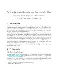

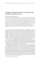
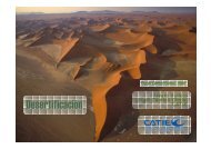
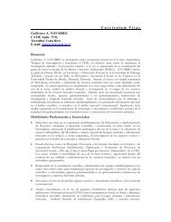

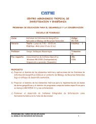
![Tratamientos y MD_2009 [Modo de compatibilidad].pdf - Catie](https://img.yumpu.com/49175499/1/190x134/tratamientos-y-md-2009-modo-de-compatibilidadpdf-catie.jpg?quality=85)