Vision-based ACC with a Single Camera: Bounds on ... - Mobileye
Vision-based ACC with a Single Camera: Bounds on ... - Mobileye
Vision-based ACC with a Single Camera: Bounds on ... - Mobileye

Create successful ePaper yourself
Turn your PDF publications into a flip-book with our unique Google optimized e-Paper software.
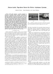
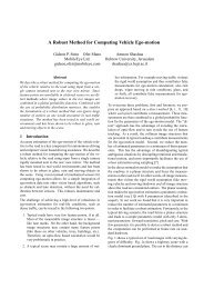
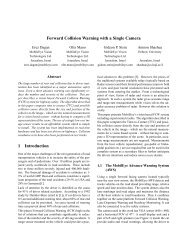
We have built a m<strong>on</strong>ocular visual processing system targetedfor mass producti<strong>on</strong> over a wide range of applicati<strong>on</strong>s.Fig. 1 shows the camera mounted near the rear-view mirror.The prototype processing box used at this stage of developmentis <str<strong>on</strong>g>based</str<strong>on</strong>g> <strong>on</strong> the PPC7410 processor. 2 . The systemruns at 10 frames per sec<strong>on</strong>d and performs target detecti<strong>on</strong>(vehicles and motorcycles) in the lane and adjacent lanes,lane mark detecti<strong>on</strong> and following, lane departure warningand cut-in calculati<strong>on</strong> using optic-flow analysis. Finally, tobe used for c<strong>on</strong>trol, it determines the range and range rateinformati<strong>on</strong> about the target vehicles.Of the many task required by the visi<strong>on</strong> sensor this paperwill focus <strong>on</strong> the issue of determining the range and rangerate. After discussing the methods for computing range andrange rate we provide an analysis of the accuracy of thosemeasurements. Finally we show some results taken duringclosed loop operati<strong>on</strong> and we compare those results to measurementsusing Radar.2 RangeSince we have <strong>on</strong>ly a single camera we must estimate therange using perspective. There are two cues which can beused: size of the vehicle in the image and positi<strong>on</strong> of the bottomof the vehicle in the image. Since the width of a vehicleof unknown type (car, van, truck etc) can vary anywherebetween 1.5m and 3m a range estimate <str<strong>on</strong>g>based</str<strong>on</strong>g> <strong>on</strong> width will<strong>on</strong>ly be about 30% accurate. It can be used as a sanity checkand possibly to check out-of-calibrati<strong>on</strong> but it is not goodenough for actuati<strong>on</strong> c<strong>on</strong>trol.A much better estimate can be achieved using the road geometryand the point of c<strong>on</strong>tact of the vehicle and the road.We will at first assume a planar road surface and a cameramounted so that the optical axis is parallel to the road surface.A point <strong>on</strong> the road at a distance Z in fr<strong>on</strong>t of thecamera will project to the image at a height y, where y isgiven by the equati<strong>on</strong>:y = f H Zwhere H is the camera height in meters.Figure 2 shows a diagram of a schematic pinhole cameracomprised of a pinhole (P) and an imaging plane (I) placedat a focal distance (f) from the pinhole. The camera ismounted <strong>on</strong> vehicle (A) at a height (H). The rear of vehicle(B) is at a distance (Z 1 ) from the camera. The point ofc<strong>on</strong>tact between the vehicle and the road projects <strong>on</strong>to theimage plane at a positi<strong>on</strong> (y 1 ). The focal distance ( f ) andthe image coordinates (y) are typically in mm and are drawnhere not to scale.2 The serial producti<strong>on</strong> hardware is <str<strong>on</strong>g>based</str<strong>on</strong>g> <strong>on</strong> a system-<strong>on</strong>-chip calledEyeQ — more details in http://www.mobileye.com(1)Figure 1: Two pictures of the compact m<strong>on</strong>ocular cameramounted near the rear-view mirror.Equati<strong>on</strong> 1 can be derived directly from the similarity of triangles:y f= H Z. The point of c<strong>on</strong>tact between a more distantvehicle (C) and the road projects <strong>on</strong>to the image plane at apositi<strong>on</strong> (y 2 ) which is smaller than (y 1 ).The camera electr<strong>on</strong>ics c<strong>on</strong>verts the image coordinates frommm to pixels and inverts the image back to the upright positi<strong>on</strong>for processing. Figure 3 shows an example sequence ofa truck at various distances. The distance from the horiz<strong>on</strong>line to the bottom of the truck is smaller when the truck ismore distant (a) than when it is close (b and c).To determine the distance to a vehicle we must first detectthe point of c<strong>on</strong>tact between the vehicle and the road (i.e.the wheels) and then we can compute the distance to thevehicle:Z = f H y . (2)In practice the camera optical axis is not aligned parallel tothe road surface. Thus the horiz<strong>on</strong> line is not in the center