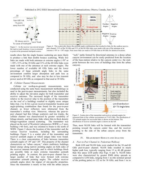
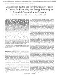
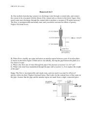
Published in 2012 IEEE International Conference on Communications, Ottawa, Canada, June 2012<strong>38</strong> <strong>GHz</strong> measurements between buildings were conducted inLOS, partially obstructed LOS, <strong>and</strong> NLOS links in clearweather, rain, <strong>and</strong> in hail storms. Worst-case attenuation of 26dB above free space was found during a severe hail storm [1].Narrowb<strong>and</strong> millimeter wave propagation during weatherevents was studied in [13] where the Laws-Parsons model wasshown to give reasonable statistical results of measuredattenuation versus rain rate at <strong>60</strong> <strong>GHz</strong>, <strong>and</strong> showed theimportance of the rain drop diameter.transmitter was placed 20 meters away from a 7 storybuilding. The receiver was moved to locations with distancesof 19 to 129 meters from the transmitter. The locations inFigure 1 offered typical urban reflectors <strong>and</strong> scatterers such asautomobiles, foliage, brick <strong>and</strong> aluminum-sided buildings,lampposts, signs, <strong>and</strong> h<strong>and</strong>rails.In order to characterize the various LOS <strong>and</strong> NLOS linkspresent at each receiver location, the narrowbeam hornantennas were systematically steered in the azimuth directionFigure 1– Overhead image of <strong>38</strong> <strong>and</strong> <strong>60</strong> <strong>GHz</strong> peer-to-peer measurement areawith transmitter location marked as TX <strong>and</strong> receiver locations as RX#.In [14], a 230 m link at 35 <strong>GHz</strong> was studied <strong>and</strong> found excessattenuation of at least 2.5 dB <strong>for</strong> all rain events, <strong>and</strong> an excessattenuation of 10 dB or more occurring <strong>for</strong> 30% of the time.II. MEASUREMENT HARDWAREThe channel sounder used here employs a variable ratePN sequence generator, adjusted to 400 Mcps <strong>for</strong> <strong>38</strong> <strong>GHz</strong>measurements <strong>and</strong> 750 Mcps <strong>for</strong> <strong>60</strong> <strong>GHz</strong>. The system is asuperheterodyne with IF frequency of 5.4 <strong>GHz</strong>, which is fed tothe millimeter wave up- <strong>and</strong> down-converters. The <strong>38</strong> <strong>and</strong> <strong>60</strong><strong>GHz</strong> switchable up <strong>and</strong> down converters were built by HughesResearch Laboratories (HRL), <strong>and</strong> contain a mixer <strong>and</strong> LOfrequency multipliers to yield carrier frequencies of 37.625<strong>and</strong> 59.4 <strong>GHz</strong>. The 37.625 <strong>GHz</strong> carrier is sent at a power of 22dBm <strong>and</strong> the 59.4 <strong>GHz</strong> carrier is sent at a power of 5 dBm.Since a sliding correlator requires a slower rate identical PNsequence, chip rates of 749.9625 MHz (slide factor of 20,000)<strong>and</strong> 399.95 MHz (slide factor of 8,000) were used <strong>for</strong> the <strong>60</strong><strong>and</strong> <strong>38</strong> <strong>GHz</strong> receivers, respectively, to provide goodprocessing gain <strong>and</strong> minimal pulse distortion. The system isable to measure at least 150dB of path loss in each b<strong>and</strong>.For <strong>38</strong> <strong>GHz</strong>, identical Ka-b<strong>and</strong> vertically polarized hornantennas with gains of 25 dBi <strong>and</strong> half-power beamwidth of7.0 o were used at the transmitter <strong>and</strong> receiver. The <strong>60</strong> <strong>GHz</strong>peer-to-peer measurements used identical U-b<strong>and</strong> verticallypolarized horn antennas with gains of 25 dBi <strong>and</strong> beamwidth of7.3 o at the transmitter <strong>and</strong> receiver. All antennas were rotatedon 3-D tripods.III.EXPERIMENTAL DESIGNA. Peer-to-Peer ChannelMeaurementsFor the peer-to-peer study, a single transmitter <strong>and</strong> tenr<strong>and</strong>om receiver locations were chosen around a pedestrianwalkway area surrounded by buildings of 1 to 12 stories. TheFigure 2– Overhead image of the outdoor cellular measurement area with thetransmitter on a 5-story rooftop <strong>and</strong> receiver located on the ground.(similar to a beam-steering antenna array). For LOS links, thetransmitter <strong>and</strong> receiver were first pointed directly at eachother, corresponding to azimuth scanning angles of 0 o <strong>for</strong> boththe transmitter <strong>and</strong> receiver. Next, the transmitter antenna waspointed at the direction of a large scatterer. Then, the receiverantenna was steered to point towards that same scatterer. If alink was successfully established, a measurement wasrecorded. Next, the transmitter orientation was left fixed onthe scatterer <strong>and</strong> the receiver antenna was then steered a full3<strong>60</strong> o to find <strong>and</strong> measure any additional links due to doublescatteringor other propagation events. These additional linkswere found at most receiver locations, with one or twoadditional receiver angles at <strong>60</strong> <strong>GHz</strong>, <strong>and</strong> one to threedifferent receiver angles at <strong>38</strong> <strong>GHz</strong>, although at substantiallylower (-20 dB typ.) signal strength. All peer-to-peer receiverlocations had a LOS path to the transmitter <strong>and</strong>, as aconsequence, no outages were found <strong>for</strong> the peer-to-peermeasurements.Measurements made at each receiver location <strong>for</strong> aparticular transmitter-receiver angle combination consisted ofthe average of eight local area point PDP measurements,where each point in the local-area was spaced equally on acircular measurement track with 10λ separation between eachpoint. Each point PDP measurement consisted of a timeaverage of 20 power delay profiles (PDPs) acquired in rapidsuccession over a fraction of second. As the receiver antennawas moved around the local area circular track, it was orientedto always point at the cause of the multipath link, as illustratedin Figure 3. The eight local area PDPs were averaged togetherto <strong>for</strong>m a local average PDP at each location. Figure 4 shows ascatter plot of the receiver <strong>and</strong> transmitter azimuth angles thatresulted in successful links. The plot shows a concentration inthe second <strong>and</strong> fourth quadrants. On the right side of Figure 4,both antennas are pointed at or near the same reflector. The
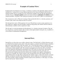
Published in 2012 IEEE International Conference on Communications, Ottawa, Canada, June 2012Figure 3 – As the receiver was moved aroundthe track at each location, it was re-orientedto point at the presumed multipath source.results show that the single bounce scattering are more likelyto produce a link than double bounce scattering. While fewlinks are made with both antennas at extreme angles (>50 o or50 o or