Analysis of a two-phase induction motor using dynamic model ...
Analysis of a two-phase induction motor using dynamic model ...
Analysis of a two-phase induction motor using dynamic model ...

You also want an ePaper? Increase the reach of your titles
YUMPU automatically turns print PDFs into web optimized ePapers that Google loves.
As. J. Energy Env. 2010, 11(01), 48-59Asian Journal onEnergy and EnvironmentISSN 1513-4121Available online at www.asian-energy-journal.infoResearch Article<strong>Analysis</strong> <strong>of</strong> a <strong>two</strong>-<strong>phase</strong> <strong>induction</strong> <strong>motor</strong> <strong>using</strong> <strong>dynamic</strong> <strong>model</strong>based on Matlab/SimulinkYuttana Kumsuwan 1 *, Watcharin Srirattanawichaikul 2 and Suttichai Premrudeepreechacharn 21 Department <strong>of</strong> Electrical Engineering, Rajamangala University <strong>of</strong> Technology Lanna, Tak Campus,Tak, Thailand.2 Department <strong>of</strong> Electrical Engineering, Chiang Mai University, Chiang Mai, Thailand.*Author to whom correspondence should be addressed, email: yuttana@doe1.eng.cmu.ac.thThis paper was originally presented at the International Conference on the Role <strong>of</strong> Universities in Hands-OnLearning, Chiang Mai, Thailand, August 2009.AbstractThis paper sets forth the development <strong>of</strong> the stationary (αβ ) reference frame <strong>model</strong> <strong>of</strong> anasymmetrical <strong>two</strong>-<strong>phase</strong> <strong>induction</strong> <strong>motor</strong>. The aim <strong>of</strong> this research was to develop and designan asymmetrical <strong>two</strong>-<strong>phase</strong> <strong>induction</strong> <strong>motor</strong> suitable for transient and steady-state analysis. Thesystem has been simulated to verify its capability such as input <strong>phase</strong> voltages, stator and rotorcurrents, electromagnetic torque and rotor speed under conditions <strong>of</strong> no-load and full-load test.The performance <strong>of</strong> an asymmetrical <strong>two</strong>-<strong>phase</strong> <strong>induction</strong> <strong>motor</strong> under these various conditionsis simulated <strong>using</strong> Matlab/Simulink and the simulation results demonstrate the feasibility <strong>of</strong> theproposed scheme.Keywords:Thailand.stationary reference, <strong>dynamic</strong> <strong>model</strong>, simulation, small power applications,IntroductionIn small power applications, asymmetrical <strong>two</strong>-<strong>phase</strong> <strong>induction</strong> <strong>motor</strong>s fed by single-<strong>phase</strong>supply have been widely used in electric machines in home appliances and industrialapplications requiring less than 5 kW [1]. Single-<strong>phase</strong> <strong>induction</strong> <strong>motor</strong>s with main andauxiliary winding can be viewed as <strong>two</strong>-<strong>phase</strong> machines, since these winding mechanisms aredisplaced ninety degrees apart from each other. Therefore, <strong>two</strong>-<strong>phase</strong> <strong>induction</strong> <strong>motor</strong>s have aconfiguration identical to single-<strong>phase</strong> <strong>induction</strong> <strong>motor</strong>s, but the input voltage applied to thestator winding terminals is independently controlled so that a <strong>two</strong>-<strong>phase</strong> voltage is supplied.In recent years, several methods that use <strong>model</strong>s for simulation <strong>of</strong> <strong>two</strong>-<strong>phase</strong> <strong>induction</strong> <strong>motor</strong>shave been proposed. The <strong>dynamic</strong>s <strong>of</strong> single/<strong>two</strong> <strong>phase</strong> <strong>induction</strong> <strong>motor</strong>s have been studied and
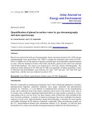
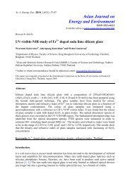
As. J. Energy Env. 2010, 11(01), 48-59 49developed with Matlab s<strong>of</strong>tware [2]. The simulation <strong>model</strong> showing start-up transients andfault transients <strong>of</strong> the different <strong>motor</strong>s are compared for performance. In Simulink development<strong>of</strong> a <strong>two</strong>-<strong>phase</strong> <strong>induction</strong> <strong>motor</strong> <strong>model</strong>, Krause’s <strong>model</strong> was analyzed on a <strong>two</strong>-<strong>phase</strong> <strong>induction</strong><strong>motor</strong> with known parameters [3]. The saturation phenomenon for main magnetic flux and itsimplications on the function characteristics <strong>of</strong> a <strong>two</strong>-<strong>phase</strong> <strong>induction</strong> <strong>motor</strong> were studied. It<strong>of</strong>fers good transient and steady-state performance. However, this technique has limitations inbeing computationally intensive.This paper presents the design and simulation <strong>of</strong> an asymmetrical <strong>two</strong>-<strong>phase</strong> <strong>induction</strong> <strong>motor</strong><strong>using</strong> a <strong>dynamic</strong> <strong>model</strong> with Matlab/Simulink. The proposed method is applicable to bothtransient and steady-states <strong>of</strong> the <strong>two</strong>-<strong>phase</strong> <strong>induction</strong> <strong>motor</strong> under conditions <strong>of</strong> no-load andfull-load test. This method is based on the analysis <strong>of</strong> the stationary (αβ ) reference frame<strong>model</strong> <strong>of</strong> an asymmetrical <strong>two</strong>-<strong>phase</strong> <strong>induction</strong> <strong>motor</strong> with a general <strong>two</strong> single-<strong>phase</strong> supplyconnected to its terminal. Following this, mathematical <strong>model</strong>ling <strong>of</strong> the asymmetrical <strong>two</strong><strong>phase</strong><strong>induction</strong> <strong>motor</strong> is undertaken based on a stationary reference frame. The <strong>dynamic</strong>simulation <strong>model</strong> <strong>using</strong> Matlab/Simulink programs is then developed and the results andperformance evaluated.Mathematical ModelThe <strong>two</strong>-<strong>phase</strong> <strong>induction</strong> <strong>motor</strong> is composed <strong>of</strong> <strong>two</strong> asymmetrical windings. Therefore, theauxiliary winding usually has fewer turns than the main winding and is displaced at ninetyelectrical degrees between these winding [4, 5]. Fig. 1 shows the schematic view <strong>of</strong> a <strong>two</strong><strong>phase</strong><strong>induction</strong> <strong>motor</strong>, illustrating that the auxiliary (α ) windings and main ( β ) windings arenot identical sinusoidal distributed windings, but are arranged in space quadrature.Figure 1. Asymmetrical <strong>two</strong>-<strong>phase</strong> <strong>induction</strong> <strong>motor</strong>.The equivalent circuits representing the asymmetrical <strong>two</strong>-<strong>phase</strong> <strong>induction</strong> <strong>motor</strong> in stationary(αβ ) reference frame are shown in Fig. 2. The <strong>dynamic</strong> <strong>model</strong> equation <strong>of</strong> asymmetrical <strong>two</strong><strong>phase</strong><strong>induction</strong> <strong>motor</strong> can be written as αβ reference frame variables. Components stator androtor voltage <strong>of</strong> the <strong>two</strong>-<strong>phase</strong> <strong>induction</strong> <strong>motor</strong> can be expressed as follows:
As. J. Energy Env. 2010, 11(01), 48-59 50R s L ls R ra r+ -r+i si mv sL lrri s-sL m(a) Auxiliary winding in α - axis.(b) Main winding in β - axis.Figure 2. Equivalent circuit <strong>of</strong> an asymmetrical <strong>two</strong>-<strong>phase</strong> <strong>induction</strong> <strong>motor</strong> in thestationary (αβ ) reference frame.vddt,sα = Rs αisα + ψsα (1)vd= R i + ψdtsβ sβ sβ sβvr α= 0 = Rr αi α+ drψr α+ aωψr rβ,dtv1= 0 = R i + d ψ − ω ψ .dt arβ rβ rβ rβ r rα,(2)(3)(4)The components <strong>of</strong> stator and rotor flux linkages equations can also be expressed as:ψ = L i + L i ,(5)sα sα sα mα rαψ = L i + L i ,(6)sβ sβ sβ mβ rβψ = L i + L i ,(7)rα mα sα rα rαψ = L i + L i .(8)rβ mβ sβ rβ rβUsing equation (5)-(8), as for the stator and rotor currents equations are given by:
As. J. Energy Env. 2010, 11(01), 48-59 51isαL=ψ− Lψrα sα mα rα,2Ls αLrα − Lmα(9)isβL=ψ− Lψrβ sβ mβ rβ,2LsβLrβ − Lmβ(10)irαL ψ=− Lψsα rα mα sα,2Ls αLrα − Lmα(11)irβL=ψ− Lψsβ rβ mβ sβ.2LsβLrβ − Lmβ(12)The equation <strong>of</strong> electromagnetic torque produced by the machine is then given by the equation:Te = pp( Lmβisβir α−Lm αisαi rβ), (13)and the mechanical <strong>dynamic</strong> is <strong>model</strong>ed by the equationdJ ωr= Te −TL.dt(14)where vs α, vsβ, vr α,vsβare the stator and rotor voltages, is α, isβ, ir α,isβare the stator and rotorcurrents, ψs α, ψsβ, ψr α,ψs βare the stator and rotor flux linkages, Rs α, Rsβ, Rr α,Rsβare the stator androtor resistances, Ls α, Lsβ, Lr α,Lsβare the stator and rotor inductances, Lmα, Lmβare themagnetizing inductances, ω ris the electrical rotor angular speed, T eis the electromagnetictorque, TLis the load torque, J is the rotor moment <strong>of</strong> inertia, d dtand a is the main per auxiliary winding turns ratio.Modelling Using Matlab/Simulinkis the differential operatorMatlab/Simulink <strong>model</strong>s were developed to examine the asymmetrical <strong>two</strong>-<strong>phase</strong> <strong>induction</strong><strong>motor</strong>. The equation from (1)-(4) and (9)-(14) have been implemented in Simulink <strong>using</strong> adifferent block. In this paper the step by step <strong>model</strong>ling <strong>of</strong> the asymmetrical <strong>two</strong>-<strong>phase</strong><strong>induction</strong> <strong>motor</strong> has been described.Figs. 3 and 4 show the subsystem block <strong>of</strong> stator and rotor voltages and currents, respectively.The electromagnetic torque and rotor speed determined is as shown in Fig. 5. Finally in Fig. 6implementation <strong>of</strong> the Simulink <strong>model</strong> <strong>of</strong> asymmetrical <strong>two</strong>-<strong>phase</strong> <strong>induction</strong> <strong>motor</strong> has beenshown.
As. J. Energy Env. 2010, 11(01), 48-59 52Figure 3. Stator and rotor voltage equations.Figure 4. Stator and rotor current equations.Figure 5. Electromagnetic torque and rotor speed equations.
As. J. Energy Env. 2010, 11(01), 48-59 53Figure 6. Implemented Simulink <strong>model</strong> as proposed in this paper.Simulation ResultsIn this section, some simulation results showing excellent performance <strong>of</strong> the proposed systemare presented. The simulation <strong>model</strong> has been developed in Matlab/Simulink environment. Theparameters <strong>of</strong> the asymmetrical <strong>two</strong>-<strong>phase</strong> <strong>induction</strong> <strong>motor</strong> are then calculated from shortcircuit and no-load measurements. Throughout the main and auxiliary winding resistances aremeasured <strong>using</strong> DC tests, while the other parameters are estimated <strong>using</strong> the stand-still andsynchronous speed tests [1]. The <strong>motor</strong> parameters are tabulated in Table 1 and the ratings are110 V, 60 Hz, 1/4 HP, and four-pole [2]. In all simulated cases, the load torque is fixed at1.0096 Nm.Table 1. Two-<strong>phase</strong> <strong>induction</strong> <strong>motor</strong> parametersRsα= 7.14 Ω Lsα= 0.2549 H Lmα= 0.2464 HRsβ= 2.02 Ω Lsβ= 0.1846 H Lmβ= 0.1772 HRrα= 5.74 Ω Lrα= 0.2542 H J = 2.92× 10 −3 kg-m 2Rrβ= 4.12 Ω Lrβ= 0.1828 H a = 1.18The simulation results for the first method, which uses <strong>dynamic</strong> <strong>model</strong>ling, is shown in Fig. 7.In Fig. 7 (a), the main and auxiliary supply voltage are identical in amplitude at 60 Hz and <strong>two</strong><strong>phase</strong> quadrature (sine and cosine wave forms) voltages were selected according to vaux.= avmain[6]. The supply voltage vaux.was fixed at 1.18v mainsince the winding turn ratio a was estimatedto be approximately 1.18. The simulation results <strong>of</strong> the <strong>dynamic</strong> response under no-load isshown in Fig. 7 (b) and (d). It can be seen that the stator and rotor currents decrease intosteady-state. At zoom pictures the stator and rotor currents. It can be seen that the stator androtor currents is well quadrature shown in Figs 7 (c) and (e). As a result, in Figs. 7 (f)-(g) it isseen that the electromagnetic torque response is generated in transient and steady-state androtor speed is constant at 1800 rpm.
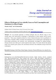
As. J. Energy Env. 2010, 11(01), 48-59 54(a)(b)i s,main(c)i s,aux.(d)i r,aux.i r,main(e)(f)(g)Figure 7. Simulation results <strong>of</strong> the main and auxiliary <strong>two</strong>-<strong>phase</strong> <strong>induction</strong> <strong>motor</strong> (v main =110V rms and v aux. = a*110V rms ) at no-load condition.(a) supply voltage (b) stator current (c) stator current at zoom (d) rotor current (e) rotor current at zoom (f) electromagnetictorque and (g) rotor speed.
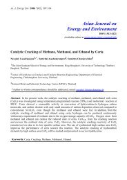
As. J. Energy Env. 2010, 11(01), 48-59 55(a)(b)i s,main(c)i s,aux.(d)i r,aux.i r,main(e)(f)(g)Figure 8. Simulation results <strong>of</strong> the main and auxiliary <strong>two</strong>-<strong>phase</strong> <strong>induction</strong> <strong>motor</strong> (v main =v aux. = 110 V rms ) at no-load condition.(a) supply voltage (b) stator current (c) stator current at zoom (d) rotor current (e) rotor current at zoom (f) electromagnetictorque and (g) rotor speed.
As. J. Energy Env. 2010, 11(01), 48-59 56Fig.8 (a) shows the simulation supply voltage for 60 Hz <strong>two</strong> <strong>phase</strong> quadrature voltages withequal magnitude <strong>of</strong> 110V rms at no-load. Under these conditions the auxiliary winding current isno longer in quadrature, and has small magnitude. This is because the larger back-emfdeveloped in the auxiliary winding prevents a useful winding current flowing when the applied<strong>phase</strong> voltage magnitude is too low as shown in Figs 8 (b)-(c). Figs 8 (d)-(e) show transient andsteady-state rotor current, respectively. In Figs. 8 (f)-(g) shows the transient responses <strong>of</strong> theelectromagnetic torque and rotor speed is 1800 rpm at no-load.The transient and <strong>dynamic</strong> response are presented in Fig 9, when applied supply voltage( vaux. = avmain.) is changed values <strong>of</strong> the load torque at 1.0096 Nm (full-load) as shown in Fig. 9(a). In Figs 9 (b)-(e), shows the transient and <strong>dynamic</strong> response <strong>of</strong> the stator and rotor windingcurrents. Fig. 9 (f)-(g) shows the transient responses <strong>of</strong> the rotor speed and the electromagnetictorque when the electromagnetic torque is changed. It is noted here that the smooth and stable<strong>of</strong> speed at 1765 rpm.The supply voltage, the stator and rotor currents waveform, the electromagnetic torque androtor speed obtained with the scheme are shown in Fig 10 (a)-(g), respectively. The rotor speedis 1765 rpm as shown in Fig. 10 (e) and the reference load torque is 1.0096 Nm. Fig. 10 (a)shows the steady-state response <strong>of</strong> the <strong>motor</strong> when it is supplied with a <strong>two</strong>-<strong>phase</strong> balancedsinusoidal supply. The simulation results <strong>of</strong> the <strong>dynamic</strong> response under full-load is shown inFig. 10 (b) and (d). It can be seen that the high ripple stator and rotor currents. Zoom onpictures the stator and rotor currents, it can be seen that the stator and rotor currents is wellquadrature shown in Figs 10 (c) and (e). The electromagnetic torque responses <strong>of</strong> the <strong>two</strong>-<strong>phase</strong><strong>induction</strong> <strong>motor</strong> when it has <strong>two</strong> asymmetrical winding are shown in Fig 10 (f). In this case, thetorque ripple under full-load is 1 Nm (rate torque).Although the supply input voltage ( vaux.= avmain) has better performance than the <strong>two</strong> <strong>phase</strong>quadrature supply voltages with equal magnitude ( vaux.= vmain), in this research workasymmetrical <strong>two</strong>-<strong>phase</strong> <strong>induction</strong> <strong>motor</strong>s were used since they are commercially availableover the counter.
As. J. Energy Env. 2010, 11(01), 48-59 57v aux.v main(a)(b)i s,main(c)i s,aux.(d)i r,aux.i r,main(e)(f)(g)Figure 9. Simulation results <strong>of</strong> the main and auxiliary <strong>two</strong>-<strong>phase</strong> <strong>induction</strong> <strong>motor</strong> (v main =110V rms and v aux. = a*110V rms ) at full-load condition.(a) supply voltage (b) stator current (c) stator current at zoom (d) rotor current (e) rotor current at zoom (f) electromagnetictorque and (g) rotor speed.
As. J. Energy Env. 2010, 11(01), 48-59 58(a)(b)i s,main(c)i s,aux.(d)i r,aux.i r,main(e)(f)(g)Figure 10. Simulation results <strong>of</strong> the main and auxiliary <strong>two</strong>-<strong>phase</strong> <strong>induction</strong> <strong>motor</strong> (v main =v aux. = 110 V rms ) at full-load condition.(a) supply voltage (b) stator current (c) stator current at zoom (d) rotor current (e) rotor current at zoom (f) electromagnetictorque and (g) rotor speed.
As. J. Energy Env. 2010, 11(01), 48-59 59ConclusionsThis paper has presented the developed and designed <strong>dynamic</strong> <strong>model</strong>ling <strong>of</strong> the asymmetrical<strong>two</strong>-<strong>phase</strong> <strong>induction</strong> <strong>motor</strong> <strong>using</strong> Matlab/Simulink. The paper has proposed <strong>model</strong> analyses thetransient and steady state characteristics with variable <strong>two</strong> <strong>phase</strong> quadrature supply voltages.The simulation results have shown that the transient and steady-state <strong>of</strong> the supply voltage, thestator and rotor winding currents, the electromagnetic torque and rotor speed under no-load andfull-load. The <strong>model</strong> gives good <strong>dynamic</strong> and steady-state response performance <strong>of</strong> theasymmetrical <strong>two</strong>-<strong>phase</strong> <strong>induction</strong> <strong>motor</strong>.AcknowledgementsThe authors would like to acknowledge financial support provided by the Office <strong>of</strong> HigherEducation Commission and the Thailand Research Fund.References1. O. Ojo and O. Omozusi, “Parameter Estimation <strong>of</strong> Single-Phase Induction Machines,”IEEE Industry Applications Conference, vol. 4, pp. 2280-2287, September/October2001.2. S. Bala, “Dynamics <strong>of</strong> Single/Two Phase Induction Motors” University <strong>of</strong> Wisconsin,Madison, 2004.3. C. Gabriela, “Simulink Implementation <strong>of</strong> Two-Phase Induction Motor Model,”International Conference on Electromechanical and Power Systems, pp. 69-72,October, 2007.4. D. H. Jang and J. S. Won, “Voltage, Frequency, and Phase-Difference Angle Control <strong>of</strong>PWM Inverters-Fed Two-Phase Induction Motors,” IEEE Transactions on PowerElectronics, vol. 9, no. 4, pp. 377-383, July, 1994.5. F. Blaabjerg, F. Lungeanu, K. Skaug, and M. Tonnes, “Evaluation <strong>of</strong> Low-CostTopologies for Two Phase Induction Motor Drives, in Industrial Application,” IndustryApplications Conference, 2002.6. E. R. Collins Jr., H. B. Puttgen, W. E. Sayle, “Single-Phase Induction Motor AdjustableSpeed Drive: Direct Phase Angle Control <strong>of</strong> the Auxiliary Winding Supply,” IndustryApplications Society Annual Meeting, vol. 1 pp. 246-252, October, 1988.