OIL By LACT Meter - Bureau of Land Management
OIL By LACT Meter - Bureau of Land Management
OIL By LACT Meter - Bureau of Land Management

Create successful ePaper yourself
Turn your PDF publications into a flip-book with our unique Google optimized e-Paper software.
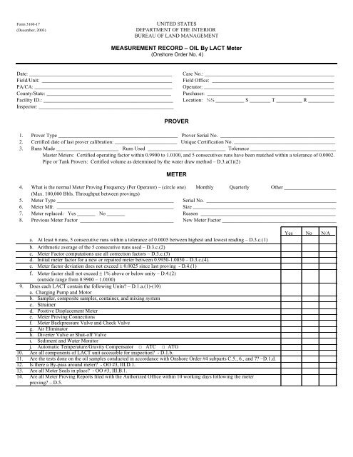
Form 3160-17(December, 2003)UNITED STATESDEPARTMENT OF THE INTERIORBUREAU OF LAND MANAGEMENTMEASUREMENT RECORD – <strong>OIL</strong> <strong>By</strong> <strong>LACT</strong> <strong>Meter</strong>(Onshore Order No. 4)Date: _______________________________________________________Field/Unit: __________________________________________________PA/CA: _____________________________________________________County/State: ________________________________________________Facility ID.: __________________________________________________Inspector: ____________________________________________________Case No.: __________________________________________________Field Office: _______________________________________________Operator: __________________________________________________Purchaser: _________________________________________________Location: ¼¼ ___________ S ________ T __________ R __________PROVER1. Prover Type ______________________________________________ Prover Serial No. ____________________________________________2. Certified date <strong>of</strong> last prover calibration: ________________________ Unique Certification No. _______________________________________3. Runs Made ________________________ Runs Used ______________________________ Tolerance _________________________________Master <strong>Meter</strong>s: Certified operating factor within 0.9900 to 1.0100, and 5 consecutives runs have been matched within a tolerance <strong>of</strong> 0.0002.Pipe or Tank Provers: Certified volume as determined by the water draw method – D.3.a(1)(2)METER4. What is the normal <strong>Meter</strong> Proving Frequency (Per Operator) – (circle one) Monthly Quarterly Other ____________________(Max. 100,000 Bbls. Throughput between provings)5. <strong>Meter</strong> Type _____________________________________________ Serial No. __________________________________________________6. <strong>Meter</strong> Mfr. _____________________________________________ Size _______________________________________________________7. <strong>Meter</strong> replaced: Yes _______ No _______ Reason ____________________________________________________8. Previous <strong>Meter</strong> Factor ____________________________________ New <strong>Meter</strong> Factor ____________________________________________a. At least 6 runs, 5 consecutive runs within a tolerance <strong>of</strong> 0.0005 between highest and lowest reading – D.3.c.(1)b. Arithmetic average <strong>of</strong> the 5 consecutive runs used – D.3.c.(2)c. <strong>Meter</strong> Factor computations use all correction factors – D.3.c.(3)d. Initial meter factor for a new or repaired meter between 0.9950-1.0050 – D.3.c.(4).e. <strong>Meter</strong> factor deviation does not exceed ± 0.0025 since last proving - D.4.(1)f. <strong>Meter</strong> factor shall not exceed ± 1% above or below unity – D.4.(2)(outside range from 0.9900 – 1.0100)9. Does each <strong>LACT</strong> contain the following Units? – D.1.a.(1)-(10)a. Charging Pump and Motorb. Sampler, composite sampler, container, and mixing systemc. Strainerd. Positive Displacement <strong>Meter</strong>e. <strong>Meter</strong> Proving Connectionsf. <strong>Meter</strong> Backpressure Valve and Check Valveg. Air Eliminatorh. Diverter Valve or Shut-<strong>of</strong>f Valvei. Sediment and Water Monitorj. Automatic Temperature/Gravity Compensator □ ATC □ ATG10. Are all components <strong>of</strong> <strong>LACT</strong> unit accessible for inspection? - D.1.b.11. Are the tests done on the oil samples conducted in accordance with Onshore Order #4 subparts C.5., 6., and 7? –D.1.d.12. Is there a <strong>By</strong>-pass around meter? - OO #3, III.D.1.13. Are all <strong>Meter</strong> Seals in place? - OO #3, III.B.1.14. Are all <strong>Meter</strong> Proving Reports filed with the Authorized Office within 10 working days following the meterproving? – D.5.Yes No N/A__
<strong>LACT</strong> Unit Component Requirements:A. Charging Pump and Motor - <strong>LACT</strong> unit shall include an electrically driven pump rated for a discharge pressure and rate that arecompatible with rating <strong>of</strong> the meter used and sized to assure turbulent flow in the <strong>LACT</strong> main stream piping (major) - D.2.a.B. Sampler1. Probe shall extend into center 1/3 <strong>of</strong> the flow piping in a vertical run, at least 3 pipe diameters downstream <strong>of</strong> any pipe fitting,always in a horizontal position (major) - D.2.b.2. Composite Sample Container shall be capable <strong>of</strong> holding sample under pressure and shall be equipped with a vapor pro<strong>of</strong> top closureand operated to prevent the unnecessary escape <strong>of</strong> vapor, and the container shall be emptied upon completion <strong>of</strong> samplewithdrawal (major) - D.2.c.3. Mixing system shall completely blend the sample into a homogeneous mixture before and during the withdrawal <strong>of</strong> a portion <strong>of</strong> thesample for testing (major) - D.2.d.C. Strainer - Shall be constructed so that it may be depressurized, opened, and cleaned, be located upstream <strong>of</strong> the meter, and be made <strong>of</strong>corrosion resistant material <strong>of</strong> a mesh size no larger than 1/4 inch (minor) - D.2.e.D. Positive Displacement <strong>Meter</strong> - Shall register volumes <strong>of</strong> oil passing through said meter determined by a system which constantly andmechanically isolated the flowing oil into segments <strong>of</strong> known volume, and be equipped with a non-resettable totalizer (major) - D.2.f.E. <strong>Meter</strong> Proving Connections - Shall be installed downstream from the <strong>LACT</strong> meter, with the line valve(s) between the inlet and outlet <strong>of</strong>the prover loop having a double block and bleed design feature to provide for leak testing during proving operations (major) - D.2.g.F. <strong>Meter</strong> Backpressure Valve and Check Valve - Shall be installed downstream from the <strong>LACT</strong> meter (major) - D.2.h.G. Air Eliminator - Shall be installed and prevent air/gas from entering the meter (minor) - D.2.i.H. Diverter Valve or Shut-<strong>of</strong>f Valve - Shall be activated by the Sediment and Water Monitor so that the valve moves to divert flow to theclean oil discharge only when it receives a positive signal, or provide a shut-<strong>of</strong>f valve configured to shut <strong>of</strong>f oil delivery upon failure toreceive a positive signal from the Sediment and Water Monitor (minor) - D.2.j.I. Sediment and Water Monitor - An internally plastic coated capacitance probe, no smaller in diameter than the skid piping, and shall bemounted in a vertical pipe located upstream from the diverter valve and the meter (minor) - D.2.k.J. Automatic Temperature/Gravity Compensator - Shall be sized according to the fluid characteristics being measured (major) - D.2.l.<strong>LACT</strong> Unit Seal Requirements:Sample probe, Sampler volume control, valves on all lines entering/leaving sampler excluding pop-<strong>of</strong>f valve, meter assembly, ATC, ATG,Temperature Recorder, Back Pressure Valve downstream <strong>of</strong> meter, any Drain Valves, and the Manual Sampling Valves.Abatement Periods:Minor: Generally 30 days.Major: Prior to Sales or removal.