THERMAL NEUTRON CONVERTER FOR IRRADIATIONS WITH ...
THERMAL NEUTRON CONVERTER FOR IRRADIATIONS WITH ...
THERMAL NEUTRON CONVERTER FOR IRRADIATIONS WITH ...

Create successful ePaper yourself
Turn your PDF publications into a flip-book with our unique Google optimized e-Paper software.
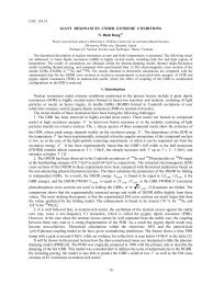
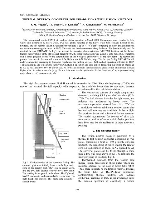
UDC 621.039.526+621.039.83<strong>THERMAL</strong> <strong>NEUTRON</strong> <strong>CONVERTER</strong> <strong>FOR</strong> <strong>IRRADIATIONS</strong> <strong>WITH</strong> FISSION <strong>NEUTRON</strong>SF. M. Wagner 1 , Th. Bücherl 2 , S. Kampfer 1, 3 , A. Kastenmüller 1 , W. Waschkowski 11 Technische Universität München, Forschungsneutronenquelle Heinz Maier-Leibnitz (FRM II), Garching, Germany2 Technische Universität München (TUM), Institut für Radiochemie (RCM), Garching, Germany3 Klinik für Strahlentherapie, Klinikum rechts der Isar, TUM, München. GermanyThe new research reactor FRM II at Garching started operation in March 2004. The compact core is cooled by lightwater, and moderated by heavy water. Two fuel plates mounted in the heavy water tank convert thermal to fastneutrons. The fast neutron flux in the connected beam tube is up to 7 ⋅ 10 8 s -1 cm -2 (depending on filters and collimation);the mean neutron energy is about 1.6 MeV. There are two irradiation rooms along the beam. The first is mainly used formedical therapy (MEDAPP facility), the second for materials characterization (NECTAR facility). At the formertherapy facility RENT at the old research reactor FRM, the same beam quality was available until July 2000. Therefore,only a small program is run for the determination of the biological effectiveness of the new beam. The neutron andgamma dose rates in the medical beam are 0.54 Gy/min and 0.20 Gy/min, resp.. The therapy facility MEDAPP is stillunder examination according to European regulations for medical devices. Full medical operation will start in 2007.The radiography and tomography facility NECTAR is in operation and aims at non-destructive inspection of objects upto 400 kg mass and 80 × 80 × 80 cm³ in size. As for fission neutrons the macroscopic cross section of hydrogen is muchhigher than for other materials (e. g. Fe and Pb), one special application is the detection of hydrogen-containingmaterials (e. g. oil) in dense materials.1. IntroductionThe high flux neutron source FRM II started its operation in 2004. Since the beginning of 2006, thereactor has attained the full capacity with respect to the available beam time so that now, externalexperimentalists find reliable conditions.CoolingDrive motorFlowcontrolThe reactor core consists of a single compact fuelelement containing 8.1 kg enriched uranium (93 %235 U). The fuel element is cooled by light water, andreflected and moderated by heavy water. Themaximum unperturbed thermal flux is 8 × 10 14 s -1 cm -2 . In addition to the usual thermal neutron beams alsohot and cold neutrons are available; further a highfluxpositron beam, and a beam of fission neutrons.The spatial requirements for sources of ultra coldneutrons as well as of neutron-rich fission productshave been met, but the realization of these sources ispending.Beam tubeD 2 O tankConverterplateFig. 1. Vertical section of the converter facility. Theconverter plates are initially located in the light waterzone of the reactor pool. They can be driven downinto the D 2 O tank (dashed contour) by a drive shaft.The cooling is integrated in the chute. The D 2 O tankhas 2.5 m diameter and surrounds the reactor core (1mright hand, not shown). The beam tube contains 4shutter drums.2. The converter facilityThe fission neutron beam is generated by athermal-to-fast neutron converter consisting of twoplates containing a total of 540 g highly enricheduranium. The same type of fuel is used in the reactorcore, i.e. a dispersion of U 3 Si 2 in Al, cladded by Al.The converter plates can be driven through a chutefrom a low flux zone above of the D 2 O-tank into theinner periphery of this tank, Fig. 1.Thermalized neutrons from the reactor coreinduce fission processes in these plates which aremounted adjacent to the nose of beam tube SR10.Thus, there is nearly no moderating material towardsthe beam tube. A B 4 C-PE-filter suppressescontaminating thermal neutrons and reducesepithermal neutrons so that, at the irradiation sites,the neutron spectrum is essentially a fission533
spectrum. During each fission process, also 7 prompt high energy photons are emitted. In order to establishthe effect of neutrons, the gamma dose rate is decreased by 3.5 cm Pb without distortion of the neutronspectrum.This facility is the successor of a similar one at the former reactor FRM called RENT which was inoperation from 1980 until July 2000. Both fission beams have been designed for multiple use, e.g., in clinicalneutron therapy, radiobiology, dosimetry, materials testing (e.g., radiation hardness), and for computerizedtomography and radiography; moreover, nuclear models have been tested using silicon and other filters forthe generation of narrow neutron spectra [1]. The beam at the FRM II is formed by a multi leaf collimator(MLC), see Fig. 2. The leaves are 1.5 cm wide and 60 cm deep, and consist of Fe, PE and Pb. Their verticalmovement allows the conformation to the radiation on the contour of the tumour. Radiography andtomography need especially narrow collimation and very strong suppression of the gamma component. Thecorresponding filter-collimator can be inserted into the beam pneumatically as well.The new fast neutron beam is equipped with redundant shutters (requirement for therapy). The beam has alarge cross section (maximum 30 × 20 cm²) into which various filters can be inserted pneumatically. Thereare two large irradiation rooms along the beam (Fig. 3), one for the patient therapy and short termexperiments, the other for permanent setups like the radiography installations.Fig. 2. Multi leaf collimator (MLC).Fig. 3. Along the fission neutron beam: the beam tubeSR10, filters, collimator and the heavily shieldedirradiation rooms for medical and technical use.3. Medical Applications (MEDAPP)3.1 Beam quality and selection of tumoursMCNP calculations assisted the design of the converter facility and were carried out from the source tothe target which consists of a polyethylene (PE) phantom. Calculated spectra are shown in Fig. 4.The basis of the physical treatment planning is the dose distribution in the depth of a water phantom. Thedistributions are dependent on the form and the size of the irradiated field. The data are measured by use of acubic water phantom with about 150 litres volume. It is equipped with precision drives for the ionizationchambers and a computerized recording.In mixed field dosimetry, two chambers with different sensitivities to the neutron and gamma componentsare necessary. One chamber consists of the electrically conducting material A150 (so-called “Shonkaplastic”)which is radiologically equivalent to human muscle tissue; the chamber volume (1 cm³) is floodedwith tissue equivalent gas on a methane basis. The second chamber is made of magnesium and flooded withargon gas. In this way, the chambers are sufficiently homogeneous so that the Bragg-Gray condition for thedetermination of the energy dose is fulfilled. The tissue equivalent (TE) chamber is sensitive to neutrons534
mainly due to its hydrogen content; the ratio of the sensitivities to the neutrons and to the gamma componentis 49:51, respectively, for a fission spectrum. Hence, the TE chamber current is essentially proportional tothe total dose rate. The Mg-Ar chamber has only little neutron sensitivity (2 %). In this way, the neutron andgamma components can be determined separately.Flux density x Energy, s -1 cm -2Neutron energy, MeVFig. 4. Monte-Carlo simulation of the neutron spectrum at the patient site in 2 cm depth of a PE phantom.Closed rhombi: unfiltered beam; open squares: beam filtered by 1cm B 4 C-PE and 1 cm Pb.A typical depth dose curve is shown in Fig. 5. Because of the dimension of the chambers, the measuredpoints start only at 17 mm depth. The first points at 0 and 10 mm depth stem from a MCNP calculation,which was normalized to the measured points. The calculation does not show the expected build-up of thegamma dose presumably due to the low spatial resolution of the calculation. Measurements at the formerRENT beam showed that the build-up is restricted to the first 4 mm of depth; the neutron component showedno effective build-up.0,7Neutron and gamma depthdose curvesfield size 9x9 cmDose rate [Gy/min]0,60,50,40,30,2DnDg0,100 20 40 60 80 100 120depth in water [mm]Fig. 5. Neutron and gamma dose rates Dn and Dg, respectively,on the beam axis with the standard filters.At present, only one combination of filters is foreseen for therapeutic irradiations; it consists of 1cm B 4 C-PE and 3.5 cm Pb. With these “standard filters”, the neutron-to-photon ratio decreases from 3.6 near to thesurface of the phantom to unity at about 10 cm depth. The half-maximum dose rate of the neutrons is at51 mm depth.535
4.3. First experimental resultsOne of the main tasks in setting into operation of a radiography/tomography facility is the determinationof all relevant parameters as there are neutron fluxes and spectra, gamma dose rates, L/D values etc. Somefirst results using the main collimator are reported next.The fission neutron flux available at the measuring position was estimated to about 4.9 ⋅ 10 6 cm -2 s -1 takinginto account the results of MCNP calculations and measured dose rates. Both data have to be verified bymeans of additional activation measurements.One important parameter of a radiography system is the L/D value, where L is the distance betweencollimator and sample position and D is the diameter of the circular collimator outlet window. It is a measureof the best available resolution. This value was determined experimentally for the main collimator by usingan iron cylinder (diameter 5 cm, height 2.56 cm) fixed at the sample manipulator and varying the distancebetween the cylinder and the detector system. A first estimation resulted in L/D = 233 ± 16. The relativelylarge standard deviation may be caused by the contribution of scattered neutrons in the cylindrical object.This will be investigated in more detail in one of the next reactor periods.The radiographs shown here were measured using the nitrogen cooled CCD camera system incombination with the pp-converter. For each radiography a set of typically 10 frames in total was measured(measurement time per frame 1 minute). Then a median filter (3 × 3) was applied on each frame and theresulting images were summed. After dark image subtraction and normalization the final radiograph of theobject is achieved.Fig. 9. Photo (left) and radiograph (right) of a step wedge made of Pb, Fe, Al, and PE (from left to right).The depth of the each step increases by 5 mm, i.e. the maximum depth is 50 mm.Fig. 10. Photo (left) and radiograph (right) of a cylinder head.538
Fig. 9 shows the photo and the corresponding radiograph of a step wedge made of lead, iron, aluminumand polyethylene (from left to right). The depth of each step increases by 5mm, i.e. the maximum depth is50mm. The evaluation of the intensity values for the individual materials derived from the radiograph incombination with the known thickness of each step enabled the calculation of the corresponding massattenuation coefficients. The derived values are 0.0195 cm 2 g -1 for lead, 0.0437 cm 2 g -1 for iron and0.0819 cm 2 g -1 for aluminum, respectively. Within the measurement uncertainty the coefficients areindependent of the thickness of the steps. For polyethylene the mass attenuation coefficients range from0.298 cm 2 g -1 for a thickness of 0 cm up to 0.322 cm 2 g -1 for a thickness of 5 cm thus showing a slight increasewith thickness.Fig. 10 shows as a further example a radiograph of a cylinder head. Turbine blades up to 30cm in heightand a maximum thickness of 12cm have been radiographed successfully, too.REFERENCES1. Koester L., Wagner F.M., Waschkowski W., Maier P., Pfister G., Senekowitsch R., Möllenstädt S., Kriegel H., RiesG., Kneschaurek P., Breit A. Physical, Biological, and Clinical Aspects of the Fission Neutron Radiation Facility atthe Munich Research Reactor FRM // Neitronnaya Fizika - International Conference on Neutron Physics, Kiev /Ed. by B. D. Kuzminov - ZNIIatominform, Moscow, 1988 - Vol. 4, P. 198-204.2. Wagner F.M. List of subjects investigated at the converter facility at FRM Garching from 1980 to 2000 // Availablefrom the author3. Kummermehr J., Magaddino V., Wagner F.M. Preclinical screening of the biological effectiveness of a therapeuticneutron beam at SR10, FRM II // In preparation.4. Bücherl T. et al., Radiography and tomography with fast neutrons at the FRM II – A status report, Appl. Rad. Isot.61 (2004) 537-540.5. Bücherl T., Lierse von Gostomski Ch., Calzada E., The NECTAR facility at FRM II: Status of the set-up of theradiography and tomography facility using fast neutrons, Proceedings of the Seventh World Conference on NeutronRadiography, Rome, Italy, September 15-21, 2002, 401-409, ISBN 88-8286-199-6.6. Yoshii K., Kobayashi H., Characterization of the YAYOI fast neutron radiography field, Nucl. Instr. Meth. A 377(1996) 68-71.7. Schatz A, Pfister G., Koch D., Stier G., Siegel C., Computer-Tomography with Fast and Thermal Neutrons, NeutronRadiography (3), Osaka, Kluwer Academic Press, 1989.КОНВЕРТЕР ТЕПЛОВЫХ НЕЙТРОНОВ ДЛЯ ОБЛУЧЕНИЯ БЫСТРЫМИ НЕЙТРОНАМИФ. М. Вагнер, Т. Бюхерль, С. Кампфер, А. Кастенмюллер, В. ВашковскиНовый исследовательский реактор FRM II в Гархинге вступил в строй в марте 2004 г. Компактная активнаязона охлаждается легкой водой. Две топливные пластины, находящиеся в корпусе с тяжелой водой,преобразуют тепловые нейтроны в быстрые. Поток быстрых нейтронов в выходном трубопроводе можетсоставлять 7 ⋅ 10 8 нейтронов/см 2 сек (в зависимости от фильтров и коллиматоров); средняя энергия нейтроновоколо 1.6 МэВ. Вдоль пучка размещены две рабочие комнаты для облучения. Первую используют главнымобразом для лечебной терапии (установка MEDAPP), вторую – для исследования материалов (установкаNECTAR). На предшествующей установке для терапии RENT, которая работала на старом реакторе FRM, былотакое же качество пучка до июля 2000 г. Поэтому только небольшая программа понадобилась для определениябиологической эффективности нового пучка. Полномасштабная медицинская работа начнется в 2007 г.Нейтронная и гамма дозовые составляющие пучка для медицинских целей составляют 0.54 и 0.20 Гр/мин.соответственно. Установка для терапии MEDAPP еще находиться в стадии отладки в соответствии с правиламиЕвропейского регулирования для медицинских установок. Установка NECTAR для радиографии и томографиинаходится в действии и ее работа направлена на обследование предметов весом до 400 кг и размерами 80 × 80 ×× 80 cм³. Поскольку для быстрых нейтронов макроскопическое сечение водорода намного выше, чем длядругих материалов (например, Fe или Pb), одним из специальных направлений является обнаружение водородосодержащихвеществ (например, нефти) в плотных материалах.КОНВЕРТЕР ТЕПЛОВИХ НЕЙТРОНІВ ДЛЯ ОПРОМІНЕННЯ ШВИДКИМИ НЕЙТРОНАМИФ. М. Вагнер, Т. Бюхерль, С. Кампфер, А. Кастенмюллер, В. ВашковскиНовий дослідницький реактор FRM II у Гархінгу вступив до дії в березні 2004 р. Компактна активна зонаохолоджується легкою водою. Дві паливні пластини, що містяться у корпусі з важкою водою, перетворюютьтеплові нейтрони у швидкі. Потік швидких нейтронів у вихідному трубопроводі може досягати7 ⋅ 10 8 нейтронів/см 2 сек (залежно від фільтрів та коліматорів); середня енергія нейтронів близько 1.6 МеВ.539