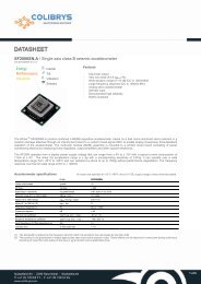
RS9010.B / Single axis tactical grade accelerometer - Colibrys
RS9010.B / Single axis tactical grade accelerometer - Colibrys
RS9010.B / Single axis tactical grade accelerometer - Colibrys

You also want an ePaper? Increase the reach of your titles
YUMPU automatically turns print PDFs into web optimized ePapers that Google loves.
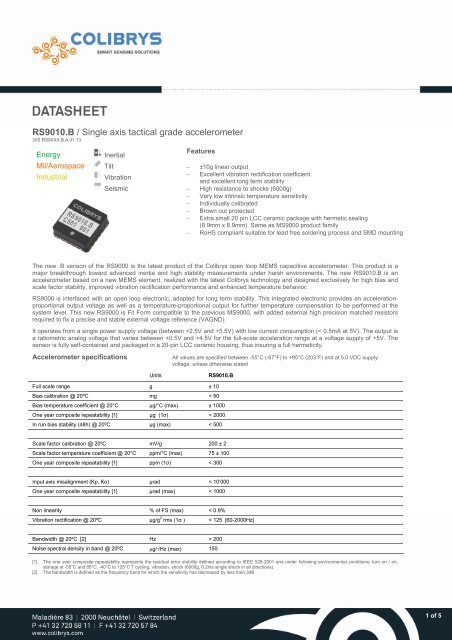
30S.RS9XXX.B.A.01.13Environmental specifications<strong>RS9010.B</strong>Operating temperature range-55°C to +125°C (-67°F to 255°F)ReliabilityResults based on MIL-HDBK-217, notice 2, are available on request.Shock resistance, survivabilityUp to 6’000 g (0.2ms half-sine, single shock and multiple shocks in direction o, p or i. Typically 10 shocks)Recovery time after shock < 1ms (after 1000g, half-sine period 1ms, shocks in direction i)Vibration 20 g rms, 20-2000 Hz (random noise, 30 minutes in each direction o, p, i)ESD sensitivityClass 2 (requirements MIL-STD-883-G, 1 Method 3015.7), Human Body Model 2kVUltrasonic cleaningThe product can not be cleaned with ultrasonic bath. Such a cleaning process will affect the sensor integrityPackagingThe packaging is a standard LCC ceramic housing with a total of 20 pins. The precise dimensions are given in the next figure and theweight of the final product is typically less than 1.5 gramsThe glass frit sealing process is qualified according to the MIL-STD-883-G and systematical leak tests are performed up to5·10 -8 atm·cm 3 /s.SMD MountingThe RS9000 is RoHS compliant suitable for lead free soldering process and SMD mounting. It must be tightly fixed to the PCB, usingthe bottom of the housing as reference plane to ensure a good <strong>axis</strong> alignment. The stress induced by the soldering of the LCC packageis a specific MEMS concern, especially when it comes to high-end capacitive sensors. In order to obtain good stress homogeneity andthe best long term stability, all the leads of the <strong>accelerometer</strong> must be soldered to the pads of the PCB. See the <strong>Colibrys</strong> ApplicationNote “LCC-48 housing, soldering conditions” available on our web site for more information about the LCC mounting process in general.Physical specifications<strong>RS9010.B</strong>PackagingNon magnetic, LCC, 20 pin housingLead finishing Au plating: 0.5 to 1.5 µmNi plating: 1.27 to 8.89 µm (typ. 3 to 5 µm)W (tungsten): 10 to 15 µmHermeticityThe product has been qualified according to MIL-STD-833-G. Hermetic sealing is systematically qualifiedat 5·10 -8 atm·cm 3 /sWeight< 1.5 gramsSize Typ. 8.9 x 8.9 x 3.23 mm (0.35 x 0.35 x 0.127 inch)Max. 9.2 x 9.2 x 3.5 mm (0.354 x 0.354 x 0.138 inch)Proximity effectThe sensor is sensitive to external parasitic capacitance. Moving metallic objects with large mass orparasitic effect at proximity of the <strong>accelerometer</strong> (mm range) must be avoided to insure best productperformancesReference plane for <strong>axis</strong> alignment LCC must be tightly fixed to the PCB, using the bottom of the housing as reference plane for <strong>axis</strong>alignment.Using the lid as reference plane or for assembly may affect specifications and product reliability(i.e. <strong>axis</strong> alignment and/or lid soldering integrity)2 of 5
30S.RS9XXX.B.A.01.13Principle of operationThe standard calibration voltage for the RS9000.B is (VDD-VSS) = 5V. Therefore, all specifications are valid for this supply voltageunless otherwise stated. Upon market request, the calibration of the product at a different voltage (between 2.5V and 5.5V) is possible.In such a case, the nominal output signal will vary according to the following equation:Vout = (VDD - VSS) / 2 + Ai * (K1 * VDD / 5 )VAGND = (VDD – VSS) / 2(1)(2)According to this equation (1), the bias and scale factor are ratiometric to the power supply voltage.A reference voltage VAGND is externally generated and provides half of the power supply, corresponding to the output voltage at zerog. All sensors are calibrated to match the ideal response curve in term of offset, gain and non-linearity.At every power-up, the microcontroller, used as memory, transfers the calibration parameters to the ASIC and then goes in a sleepmode. During this initialization phase, which takes less than 50ms, the current consumption goes up to max. 1,5mA @ 5V and at roomtemperature. Then, the normal operating current is set and remains less than 400A under similar conditions.The following model describes each sensor:Vout = k 1* (k 0 +A i +k 2 A i 2 +k 3 A i 3 +k p A p +k o A o +k ip A i A p +k io A i A o +E)where Ai, Ap, Ao are the accelerations for each axes of the sensor with:I : input <strong>axis</strong> (z <strong>axis</strong>)p: pendulous <strong>axis</strong> (y <strong>axis</strong>)o: output <strong>axis</strong>, also named pivot or hinge <strong>axis</strong> (x <strong>axis</strong>) K1 is <strong>accelerometer</strong> scale factor [V/g] K0 is bias [g] K2 is second order non linearity [g/g2] K3 is third order non-linearity [g/g3] Kp is pendulous cross <strong>axis</strong> non linearity [rad] Ko is output cross <strong>axis</strong> non linearity [rad] Kip, Kio are cross-coupling coefficients [rad/g] E is the residual noise [g]Electrical specificationsInput voltage (VDD – VSS)<strong>RS9010.B</strong>2.5 to 5.5 VDC. The standard voltage for calibration is 5.0 VDCOutput voltage range From 0.5 to 4.5 VDC @ 5.0 VDC input voltage (VDD/2 at 0g)Operating current consumptionInitialization & reset currentconsumptionReset< 400 A @ 5.0 VDCTyp. 1500 A @ 5.0 VDC during the initialization phase (less than 35 ms at room temperature)The sensor is Brown out protected. A reset occurs when the power supply jumps more than -0.46 V with aslope >380V/s or if the power supply drops below 2.2V. The recovery time is typ. 25 ms (max 35 ms)Output impedance / load Min. 50 k at Vout (pin 8) and VAGND (pin 5)Max. 50 pF at Vout (pin 8) and Max. 100 F at VAGND (pin 5)Temperature sensor specificationsOutput Voltage at 20°CSensitivityLong term stabilityAccuracyTyp: 1.632 VTyp: -11.77 mV/°CMax -0.03°C to +0.09°C (1000h @ 150°C) 5°C (From -40°C to 125°C)3 of 5
30S.RS9XXX.B.A.01.13Temperature compensationThe RS9000 delivers an output signal without any internal temperature compensation. The intrinsic temperature coefficient is quitesmall but can be further improved through a calibration, using the temperature provided by the internal temperature sensor. Third ordercompensation is generally required for a coherent modeling of a RS9000.B.Sensor connections and power supply requirementsThe detailed block diagram is given in the next figureComponents in the LCC20 packaging:1-<strong>axis</strong> silicon MEMS sensorASICMicrocontrollerTemperature sensorPull down resistorExternal components to the LCC20Decoupling capacitors [C]Match resistors [R]It is mandatory to implement two very high precision matched resistors [R] of 10 k each outside the LCC package, as close aspossible to the <strong>accelerometer</strong> between VDD and VAGND and between VSS and VAGND. This ultra-high precision resistive divider isused as internal reference voltage by the interface circuit. More precise information is available on the dedicated application note“VAGND Reference on RS9000” (30TN.VAGND RS9X.x.xx.xx).It is also necessary to use decoupling capacitors [C] of 1F each between VDD and VAGND and between VAGND and VSS, placedalso as close as possible from the <strong>accelerometer</strong>. COG or X7R @ 5% capacitor types are recommended. On top, the VAGND trackshould be as short as possible. Any other setup will potentially affect the bias calibration and stability.QualityPin RS9000 Description Notes4 VDD Power supply5 VAGND Accelerometer output reference voltage6 VSS Ground7 VO Temperature sensor output8 Vout Accelerometer output signal16 VPP (<strong>Colibrys</strong> internal calibration pin) Must be connected to VSS17 SCK (<strong>Colibrys</strong> internal calibration pin) Must be connected to VSS18 SDA (<strong>Colibrys</strong> internal calibration pin) Must be connected to VSS<strong>Colibrys</strong> is ISO 9001:2008, ISO 14001:2004 and OHSAS 18001:2007 certified<strong>Colibrys</strong> is in compliant with the European Community Regulation on chemicals and their safe use (EC 1907/2006) REACHRS9000 products comply with the EU-RoHS directive 2002/95/EC (Restrictions on hazardous substances) regulationsRS9000 products are compliant with the Swiss LSPro : 930.11 dedicated to the security of productsNote:RS9000 <strong>accelerometer</strong>s are available for sales to professional onlyLes accéléromètres RS9000 ne sont disponibles à la vente que pour des clients professionnelsDie Produkte der Serie RS9000 sind nur im Vertrieb für kommerzielle Kunden verfügbarGli accelerometri RS9000 sono disponibili alla vendita soltanto per clienti professionistiRecycling : please use appropriate recycling process adapted to electrical and electronic components4 of 5
30S.RS9XXX.B.A.01.13Glossary of parameters of the Data Sheetg[m/s 2 ]Unit of acceleration, equal to standard value of the earth gravity (Accelerometer specifications and data supplied by <strong>Colibrys</strong> use 9.80665 m/s²)Bias [mg]The <strong>accelerometer</strong> output at zero gBias stability [mg]Maximum drift of the bias residual error after 4 th order compensation under extreme variation of external conditions (aging, temperature cycles, shock,vibration)Bias temperature coefficient [g/°C]Maximum variation of the bias calibration under variable external temperature conditions (slope of the best fit straight line through the curve of bias vs.temperature). Bias Temperature Coefficient is specified at 20°CScale factor sensitivity [mV/g]The ratio of the change in output (in volts) to a unit change of the input (in units of acceleration); thus given in mV/gScale factor temperature coefficient [ppm/°C]Maximum deviation of the scale factor under variable external temperature conditionsTemperature sensitivitySensitivity of a given performance characteristic (typically scale factor, bias, or <strong>axis</strong> misalignment) to operating temperature, specified generally at 20°C.Expressed as the change of the characteristic per degree of temperature change; a signed quantity, typically in ppm/°C for scale factor and µg/°C forbias. This figure is useful for predicting maximum scale factor error with temperature, as a variable when modelling is not accomplishedAxis alignment [mrad]The extent to which the <strong>accelerometer</strong>'s true sensitive <strong>axis</strong> deviates from being perfectly orthogonal to the <strong>accelerometer</strong>'s reference mounting surfacewhen mounted to a flat surfaceResolution, Threshold [mg]Value of the smallest acceleration that can be significantly measuredNon-linearity [% of FS]The maximum deviation of <strong>accelerometer</strong> output from the best linear fit over the full operating range. The deviation is expressed as a percentage of thefull-scale output (+A FS )Bandwidth [Hz]Frequency range from DC to F-3dB where the variation of the frequency response is less than –3dB or -5% for vibration sensorsResonant frequency nominal [kHz]Typical value of the resonant frequency of the mounted systemNoise [V/√Hz or g/√Hz]Undesired perturbations in the <strong>accelerometer</strong> output signal, which are generally uncorrelated with desired or anticipated input accelerations<strong>Colibrys</strong> reserves the right to change these data without notice.5 of 5