GD/GS/GSR/GR/GK-24/230
GD/GS/GSR/GR/GK-24/230
GD/GS/GSR/GR/GK-24/230
- No tags were found...

Create successful ePaper yourself
Turn your PDF publications into a flip-book with our unique Google optimized e-Paper software.
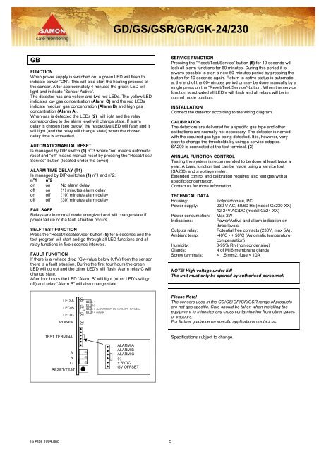
<strong>GD</strong>/<strong>GS</strong>/<strong>GS</strong>R/<strong>GR</strong>/<strong>GK</strong>-<strong>24</strong>/<strong>230</strong>GBFUNCTIONWhen power supply is switched on, a green LED will flash toindicate power ”ON”. This will also start the heating process ofthe sensor. After approximately 4 minutes the green LED willlight and indicate ”Sensor Active”.The detector has one yellow and two red LEDs. The yellow LEDindicates low gas concentration (Alarm C) and the red LEDsindicate medium gas concentration (Alarm B) and high gasconcentration (Alarm A).When gas is detected the LEDs (2) will light and the relaycorresponding to the alarm level will change state. If alarmdelay is chosen (see below) the respective LED will flash and itwill light (and the relay will change state) when the chosendelay time is exceeded.AUTOMATIC/MANUAL RESETIs managed by DIP switch (1) n o 3 where “on” means automaticreset and “off” means manual reset by pressing the “Reset/Test/Service”-button (located under the cover).ALARM TIME DELAY (T1)Is managed by DIP-switches (1) n o 1 and n o 2:n o 1 n o 2on on No alarm delayoff on (1) minutes alarm delayon off (10) minutes alarm delayoff off (30) minutes alarm delayFAIL SAFERelays are in normal mode energized and will change state ifpower failure or if a fault situation occurs.SELF TEST FUNCTIONPress the “Reset/Test/Service”-button (5) for 5 seconds and thetest program will start and go through all LED functions and allrelay functions in five seconds intervals.FAULT FUNCTIONIf there is a voltage drop (GV-value below 0,1V) from the sensorthere is a fault situation. During the first four hours the greenLED will go out and the other LED’s will flash. Alarm relay C willchange state.After four hours the LED “Alarm B” will light (other LED’s will gooff) and relay “Alarm B” will also change state.SERVICE FUNCTIONPressing the ”Reset/Test/Service” button (5) for 10 seconds willlock all alarm functions for 60 minutes. During this period it isalways possible to start a new 60-minutes period by pressing thebutton for 10 seconds again. Return to active status is automaticat the end of the 60-minutes period or may be done manually by asingle press on the “Reset/Test/Service”-button. When the servicefunction is activated all LED’s will flash and all relays will be innormal mode position.INSTALLATIONConnect the detector according to the wiring diagram.CALIBRATIONThe detectors are delivered for a specific gas type and othercalibrations are normally not necessary. The detector is namedwith the required gas type being detected. It is, however, veryeasy to change the thresholds by using a service adapter.SA200 is connected at the test terminal. (3)ANNUAL FUNCTION CONTROLTesting the system is recommended to be done at least twice ayear. A basic function test can be made using a service tool(SA200) and a voltage meter.Extended control and calibration requires also test gas with aspecific concentration.Contact us for more information.TECHNICAL DATAHousing:Polycarbonate, PCPower supply: <strong>230</strong> V AC, 50/60 Hz (model Gx<strong>230</strong>-XX)12-<strong>24</strong>V AC/DC (model Gx<strong>24</strong>-XX)Power consumption: Max 2WIndications:Power/Active and alarm indication onthree levels.Outputs relay: Potential free contacts (<strong>230</strong>V, max 5A) .Ambient temp: -40 0 C - + 50 0 C (Automatic temperaturecompensation)Humidity:0-95% Rh (non condensing)Glands:4 of M16 membrane glandsScrew terminals: < 1,5 mm2, fuse < 10ANOTE! High voltage under lid!The unit must only be opened by authorised personnel!LED ALED BLED CPOWERONn 1n 2n 3 ALARM RESET: ON=AUTO, OFF=MANUELLn 4 not usedPlease Note!The sensors used in the <strong>GD</strong>/<strong>GS</strong>/<strong>GR</strong>/<strong>GK</strong>/<strong>GS</strong>R range of productsare not gas specific. Care should be taken when installing theequipment to minimize any cross contamination from other gasesor vapours.For further guidance on specific applications contact us.TEST TERMINALSpecifications subject to change.ABCRESET/TESTALARM AALARM BALARM C(-)+ 5VDCGV OFFSETIS Atos 1004.doc 5