Read Article - Concepts NREC
Read Article - Concepts NREC
Read Article - Concepts NREC

You also want an ePaper? Increase the reach of your titles
YUMPU automatically turns print PDFs into web optimized ePapers that Google loves.
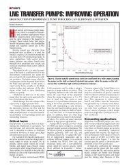
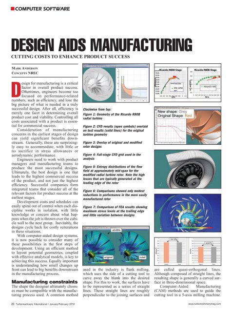
COMPUTER SOFTWAREDESIGN AIDS MANUFACTURINGCUTTING COSTS TO ENHANCE PRODUCT SUCCESSMARK ANDERSONCONCEPTS <strong>NREC</strong>Design for manufacturing is a criticalfactor in overall product success.Oftentimes, engineers become toofocused on performance-relatednumbers, such as efficiency, and lose thebig picture of what is needed in a trulysuccessful design. After all, efficiency ismerely one facet in determining overallproduct cost and viability. Controlling allcosts associated with a product is essentialfor commercial success.Consideration of manufacturingconcerns in the earliest stages of designcan yield significant benefits downstream.Generally, these are surprisinglyeasy to accommodate, with little orno sacrifice in stress allowances oraerodynamic performance.Engineers need to work with productmanagers and manufacturing teams toproduce the most successful designs.Ultimately, the best design is one thatleads to the highest commercial successof the product, and not just the highestefficiency. Successful companies formintegrated teams that consider all of therelevant factors for product success at theearliest stages.Development costs and schedules caneasily spiral out of control when each disciplineworks in isolation, with littleknowledge or concern about what happenswhen the job is thrown over the cubiclewall to the next group. Inevitably, thedesigns cycle back for costly reiterationsin these situations.With computer-aided design systems,it is now possible to consider many ofthese possibilities in the first steps ofdevelopment. Using an efficient methodto layout potential geometries, coupledwith effective analytical models, is key toachieving this success. Equally importantis understanding how small changes upfront can lead to big benefits downstreamin the manufacturing process.Manufacturing constraintsThe shape the designer ultimately choosesmust be compatible with the manufacturingprocess used. A common methodClockwise from top:Clockwise from top:Figure 1: Geometry of the Ricardo R80Bradial turbineFigure 2: CFD results (open symbols) overlaidon test results (solid lines) for the originalturbine geometryFigure 3: Overlay of original and modifiedrotor designsFigure 4: Full-stage CFD grid used in theanalysisFigure 5: Entropy distributions of the flowfield at approximately mid-span for themodified radial turbine rotor. Note the highlosses that are typically generated at theleading edge of the rotorFigure 6: Comparisons showed only modestreductions in performance in the more easilymanufactured rotorFigure 7: Comparison of FEA results showingmaximum stress levels at the trailing edgeand little variation between designsused in the industry is flank milling,which uses the side of a cutting tool tocarve away the blank into the desiredshape. For this to work, the surfaces haveto be represented as a series of straightlines. These straight lines are roughlyperpendicular to the joining surfaces andare called quasi-orthogonal lines.Although composed of straight lines, theresulting shape is generally a curved surfacein three-dimensional space.Computer-Aided Manufacturing(CAM) methods are used to guide thecutting tool in a 5-axis milling machine.26 Turbomachinery International • January/February 2010 www.turbomachinerymag.com
Clockwise from topFigure 8: Original twisted blade (dashed line,grey) compared to the simpler extruded design(solid line, red)Figure 9: Relative Mach number distributionsat roughly 70% spanFigure 10: CFD comparison of aerodynamicperformanceFailure to represent the surfaces with truequasi-orthogonals forces a more tediousand slower point-milling method. Fiveaxismachining methods tend to dominatethe compressor industry and the lowertemperature regions of turbines.Improved cutting methods, more accurategeometry results, and the superior surfacefinish are favoring 5-axis machining inother industries that have traditionallyused casting.Casting methods come with their ownunique restrictions. Chief among them isthe ability to pull the mold from the product.Various methods and ranges of costsexist to accomplish this. State-of-the-artmethods require complex three-dimensionalcalculations to determine if properclearances are present to free the castingas the molding components are pulledand twisted away.At the heart of any viable designmethod is the ability to define andmanipulate the geometry in a convenientway. Ideally, the Computer AidedDesign (CAD) system would hold thegeometry to a predetermined parameterizationthat is compatible with the manufacturingmethod needed. Several CAEproducts are available specifically forturbomachinery to do this. The mostadvanced allow a range of differentparameterizations and provide modelingmethods that give clear feedback on performance,which enables the designer tomake the optimum trade-offs on performance,stress levels, overall geometricconstraints, and manufacturing costs.In order to demonstrate some of thesimple principles of design for manufacturing,two sample cases are demonstratedbelow. Each of them will be modifiedin a specific way for better manufacturability.The results will show how easy itcan be to reduce manufacturing time andcosts, and how small the sacrifices instress levels and aerodynamic performancecan be. These cases are:• A radial turbine modified to conformto a quasi-orthogonal definition forflank milling• An axial turbine rotor significantlyreshaped to allow an inexpensive, extrudedtype of bladeMaintaining performanceRadial turbines historically have usedcasting to produce rotors. Today, 5-axismachining is increasingly being used.This raises an issue with the way radialturbine blades have traditionally beenlaid out. Stress concerns tend to dominatein radial turbines. The high temperaturesfound in turbines tend to push the structurallimits of the material. Also, aerodynamically,turbines are inherently lesssensitive than compressors.For these reasons, radial turbinesgenerally have a “radial” blade definition,where the blades radiate out directlyfrom the axis of rotation. This limitsall of the stresses in the blades to pullstressfrom the centrifugal forces ofrotation, which essentially eliminatebending stresses. This minimizes overallstress levels, albeit with a significantreduction in the degree of freedom thedesigner has to work with. A radialblade may or may not be suitable forcasting, but it is mathematically impossiblefor it to take on a ruled elementshape necessary for 5-axis flank milling.To bypass this problem, we will breakwith engineering tradition and lay out anew design based on pure quasi-orthogonallines for efficient 5-axis machining.Our baseline design is one of the famousRicardo series of radial turbines extensivelytested and documented in the1950s and 1960s (Figure 1).Figure 2 shows the ComputationalFluid Dynamics (CFD) results for thisturbine compared with test data. Notonly do the CFD results show an excellentcomparison to test data, they alsoshow how conveniently the performancecorrelates with the velocity ratio(U/c), defined as the tip rotor speeddivided by the ideal velocity expendedout to the exit pressure. The variousflow points and rotational speeds alltend to fall on this single line; hence, itis the preferred method of plotting performance.The excellent comparisonbetween the test results and analyticalsolutions gives a high degree of confidencein quantifying the performancechange for the design modification.Comparison of the baseline design(red) to the modified design (grey) inFigure 3 shows little difference in theoverall shape. As long as key parameters,such as radius and inlet and outlet bladeangles are kept unchanged, the geometrycan be reparameterized with remarkablylittle change in overall shape. Althoughthe final shape is only modestly changedin three-dimensional space, the newgeometry can now be produced muchmore efficiently by 5 axis machiningNext, we will confirm that these geometricchanges are structurally and aerodynamicallysmall as well. We will useCFD (Figure 4) and Finite ElementAnalysis (FEA) again to quantify theimpact of the geometry change. Figure 5is a snapshot of the grid around the nozzleblade and a further perspective of themesh for the entire stage used in theCFD. This solution used a total of nearly600,000 grid points and ran for aboutfive hours. Figure 5 shows a plot ofentropy distribution from the modifiedgeometry solution.The bottom-line change in performancewas small for this example. Onlyabout one-tenth of one percent of efficiencywas lost with this design modification(Figure 6) . In reality, the changewould most likely result in a net gain onthe test stand. No attempt was made inthe CFD to account for the higher qualitysurface finish that would result from thismanufacturing process. This benefitwould most likely outweigh the tiny lossin efficiency from changing the grossblade shape.How do the stress levels compare?This is most critical, since controlling thestress levels is the primary motivation forusing a purely radial blade layout. Theresults of FEA analysis show only anextremely small variation in the case:less than one-tenth of one percent.Looking deeper into the results, we canclearly see why.www.turbomachinerymag.comJanuary/February 2010 • Turbomachinery International 27
The pure radial and modified ruledelementlines are essentially the same atthe trailing edge. In other words, theyare mathematically identical at that location,since they happen to have the sameorientation. By contrast, the leadingedge defining lines (top of Figure 7) are90 degrees apart, and the resulting shapeis quite different. Because the maximumstress level is at the base of the trailingedge, it stands to reason that the stresslevels will be similar as well.A big change in shapeThe second case is a radical departure fromthe previous case in which there was onlya subtle difference in shape (and ultimatelyperformance). However, in this case, thereis a significant difference in shape (Figure8). The question then arises: Is this moresignificant change acceptable?The baseline shape of this turbine rotorblade is a fairly typical twisted design. Themodified design is without twist and canpotentially be manufactured in a simpleextrusion-type process for blading withhigh aspect ratio, such as this example.Again we use CFD to quantify the differenceaerodynamically. FEA analysis willbe bypassed in this case, since twist imposesadditional stresses on the blade and themodified untwisted design is virtually guaranteedto have a lower stress level.CFD results of relative Mach numberfor this single-stage turbine are shown inFigure 9. Note that the modified bladeshape is the rotor (downstream blade),while the upstream stator on the left hasbeen unchanged in this study.Once again, the penalty paid for thisgeometric change is surprisingly small,about one-quarter of one percent in overallstage efficiency. The mass flow changeat the fixed pressure ratio is less than onetenthof one percent (Figure 10).Whether or not such a change makessense from a product value point of viewdepends on the circumstances. Most likely,a one-quarter percent drop in efficiencywould be unacceptable for a high-performanceaircraft engine. On the other hand, asmall-scale turbine in a highly price-competitivemarket could certainly benefitfrom reduced manufacturing costs. TINote: All figures in this article are from <strong>Concepts</strong><strong>NREC</strong>’s Agile Engineering Design System.References1. Qiu, X., Anderson, M. R., Baines, N. C.,"Meanline Modeling of Radial InflowTurbine with Variable Area Nozzle," ASMEGT2009-59170, ASME Turbo Expo 2009:Power for Land, Sea and Air, 2009.2. Hiett and Palmer, "D.I.G.T. Radial InflowTurbine, Cold Tests on Turbine B, Turbine Aand Turbine D," Engineering Report 1381,Ricardo & Co. Engineers, 1956.3. Anderson, M. R., "Optimization ofTurbomachinery - Validation AgainstExperimental Results," Current Trends inDesign and Computation of Turbomachinery,Prague, 2009.4. Anderson, M. R., Gu, F., MacLeod, P. D.,"Application and Validation of CFD in aTurbomachinery Design System," IMECE2003-44217, 2003 Proceedings of the ASMEInternational Mechanical Engineering Congressand R&D Expo, Washington, D. C., 2003.AuthorMark Anderson is Vice President ofSoftware Development at <strong>Concepts</strong> <strong>NREC</strong>.(www.conceptsnrec.com)28 Turbomachinery International • January/February 2010 www.turbomachinerymag.com