
You also want an ePaper? Increase the reach of your titles
YUMPU automatically turns print PDFs into web optimized ePapers that Google loves.
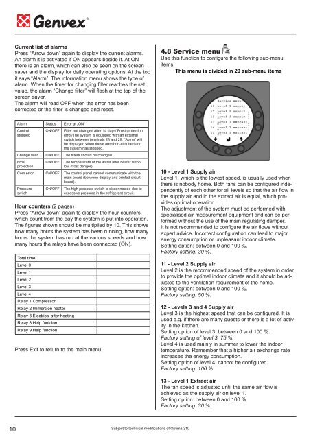
Current list of alarmsPress “Arrow down” again to display the current alarms.An alarm it is activated if ON appears beside it. At ONthere is an alarm, which can also be seen on the screensaver and the display for daily operating options. At the topit says “Alarm”. The information menu shows the type ofalarm. When the timer for changing filter reaches the setvalue, the alarm “Change filter” will flash at the top of thescreen saver.The alarm will read OFF when the error has beencorrected or the filter is changed and reset.4.8 Service menuUse this function to configure the following sub-menuitems.This menu is divided in 29 sub-menu itemsAlarm Status Error at „ON“ControlstoppedON/OFFFilter not changed after 14 days/ Frost protectionerror/The system is equipped with an externalswitch between terminals 28 and 29. “Alarm” willbe displayed when these are short-circuited andthe system has stopped.Change filter ON/OFF The filters should be changed.FrostprotectionON/OFFThe temperature of the water after heater is toolow (frost danger).Com error ON/OFF The control panel cannot communicate with themain board (between display and printed circuitboard).PressureswitchON/OFFThe high pressure switch is disconnected due toexcessive pressure in the refrigerant circuit.Hour counters (2 pages)Press “Arrow down” again to display the hour counters,which count from the day the system is put into operation.The figures shown should be multiplied by 10. This showshow many hours the system has been running, how manyhours the system has run at the various speeds and howmany hours the relays have been connected (ON).Total timeLevel 0Level 1Level 2Level 3Level 4Relay 1 CompressorRelay 2 Immersion heaterRelay 3 Electrical after heatingRelay 8 Help funktionRelay 9 Help functionPress Exit to return to the main menu.10 - Level 1 Supply airLevel 1, which is the lowest speed, is usually used whenthere is nobody home. Both fans can be configured independentlyof each other for all levels so that the air flow inthe supply air and in the extract air is equal, which providesoptimal operation.The adjustment of the system must be performed withspecialised air measurement equipment and can be performedwithout the use of the main regulating damper.It is not recommended to configure the air flows withoutexpert advice. Incorrect configuration can lead to majorenergy consumption or unpleasant indoor climate.Setting option: between 0 and 100 %.Factory setting: 30 %.11 - Level 2 Supply airLevel 2 is the recommended speed of the system in orderto provide the optimal indoor climate and it should be adjustedto the ventilation requirement of the home.Setting option: between 0 and 100 %.Factory setting: 50 %.12 - Levels 3 and 4 Supply airLevel 3 is the highest speed that can be configured. It isused e.g. if there are many guests or there is a lot of activityin the kitchen.Setting option of level 3: between 0 and 100 %.Factory setting of level 3: 75 %.Level 4 is used mainly in summer to lower the indoortemperature. Remember that a higher air exchange rateincreases the energy consumption.Setting option of level 4: cannot be configured.Factory setting: 100 %.13 - Level 1 Extract airThe fan speed is adjusted until the same air flow isachieved as the supply air on level 1.Setting option: between 0 and 100 %.Factory setting: 30 %.10Subject to technical modifications of <strong>Optima</strong> <strong>310</strong>