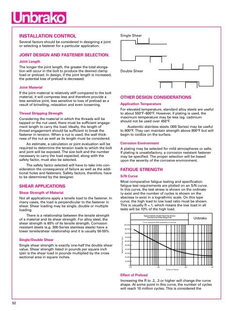
INSTALLATION CONTROLSeveral factors should be considered in designing a jointor selecting a fastener for a particular application.Single ShearJOINT DESIGN AND FASTENER SELECTION.Joint LengthThe longer the joint length, the greater the total elongationwill occur in the bolt to produce the desired clampload or preload. In design, if the joint length is increased,the potential loss of preload is decreased.Joint MaterialIf the joint material is relatively stiff compared to the boltmaterial, it will compress less <strong>and</strong> therefore provide aless sensitive joint, less sensitive to loss of preload as aresult of brinelling, relaxation <strong>and</strong> even loosening.Thread Stripping StrengthConsidering the material in which the threads will betapped or the nut used, there must be sufficient engagementlength to carry the load. Ideally, the length ofthread engagement should be sufficient to break thefastener in tension. When a nut is used, the wall thicknessof the nut as well as its length must be considered.An estimate, a calculation or joint evaluation will berequired to determine the tension loads to which the bolt<strong>and</strong> joint will be exposed. The size bolt <strong>and</strong> the numbernecessary to carry the load expected, along with thesafety factor, must also be selected.The safety factor selected will have to take into considerationthe consequence of failure as well as the additionalholes <strong>and</strong> fasteners. Safety factors, therefore, haveto be determined by the designer.SHEAR APPLICATIONSShear Strength of MaterialNot all applications apply a tensile load to the fastener. Inmany cases, the load is perpendicular to the fastener inshear. Shear loading may be single, double or multipleloading.There is a relationship between the tensile strengthof a material <strong>and</strong> its shear strength. For alloy steel, theshear strength is 60% of its tensile strength. Corrosionresistant steels (e.g. 300-Series stainless steels) have alower tensile/shear relationship <strong>and</strong> it is usually 50-55%Single/Double ShearSingle shear strength is exactly one-half the double shearvalue. Shear strength listed in pounds per square inch(psi) is the shear load in pounds multiplied by the crosssectional area in square inches.Double ShearOTHER DESIGN CONSIDERATIONSApplication TemperatureFor elevated temperature, st<strong>and</strong>ard alloy steels are usefulto about 550°F–600°F. However, if plating is used, themaximum temperature may be less (eg. cadmiumshould not be used over 450°F.Austenitic stainless steels (300 Series) may be usefulto 800°F. They can maintain strength above 800°F but willbegin to oxidize on the surface.Corrosion EnvironmentA plating may be selected for mild atmospheres or salts.If plating is unsatisfactory, a corrosion resistant fastenermay be specified. The proper selection will be basedupon the severity of the corrosive environment.FATIGUE STRENGTHS/N CurveMost comparative fatigue testing <strong>and</strong> specificationfatigue test requirements are plotted on an S/N curve.In this curve, the test stress is shown on the ordinate(y-axis) <strong>and</strong> the number of cycles is shown on theabscissa (x-axis) in a lograthmic scale. On this typecurve, the high load to low load ratio must be shown.This is usually R =.1, which means the low load in alltests will be 10% of the high load.Maximum Stress (psi)100,000Typical Unbrako <strong>Socket</strong> Head Cap ScrewsS-N Curve for Finite Fatigue LifeCurve represents 90% probability of survival90,00080,00070,00060,00050,00040,00030,00020,00010,000010 4 10 5 Cycles to FailureSPS10 6 R=0.110 7Effect of PreloadIncreasing the R to .2, .3 or higher will change the curveshape. At some point in this curve, the number of cycleswill reach 10 million cycles. This is considered the52
SCREW FASTENER THEORY & APPLICATIONSendurance limit or the stress at which infinite life mightbe expected.Modified Goodman/ Haigh Soderberg CurveThe S/N curve <strong>and</strong> the information it supplies will notprovide the information needed to determine how anindividual fastener will perform in an actual application.In application, the preload should be higher than any ofthe preloads on the S/N curve.Therefore, for application information, the modifiedGoodman Diagram <strong>and</strong>/or the Haigh Soderberg Curveare more useful. These curves will show what fatigueperformance can be expected when the parts are properlypreloaded.Stress (ksi)18016014012010080604020MODIFIED GOODMAN DIAGRAMUNBRAKO TYPICAL SHCS#8–323/8–165 x 10 6 Cycles Run-Out90% Probability of Survival3/8–245/8–11VDI 2230 Prediction for #8 RTBHT (99% PS)VDI 2230 Prediction for 5/8 RTBHT (99% PS)00 20 40 60 80Mean Stress (ksi)METHODS OF PRELOADINGSPS1/4–20 (2 x 10 6 cycles)100 120 140 160 180ElongationThe modulus for steel of 30,000,000 (thirty million) psimeans that a fastener will elongate .001 in/in of lengthfor every 30,000 psi in applied stress. Therefore, if 90,000psi is the desired preload, the bolt must be stretched .003inches for every inch of length in the joint.This method of preloading is very accurate but itrequires that the ends of the bolts be properly prepared<strong>and</strong> also that all measurements be very carefully made.In addition, direct measurements are only possible whereboth ends of the fastener are available for measurementafter installation. Other methods of measuring lengthchanges are ultrasonic, strain gages <strong>and</strong> turn of the nut.TorqueBy far, the most popular method of preloading is bytorque. Fastener manufacturers usually have recommendedseating torques for each size <strong>and</strong> materialfastener. The only requirement is the proper sizetorque wrench, a conscientious operator <strong>and</strong> theproper torque requirement.StrainSince stress/strain is a constant relationship for anygiven material, we can use that relationship just as theelongation change measurements were used previously.Now, however, the strain can be detected from straingages applied directly to the outside surface of the boltor by having a hole drilled in the center of the bolt <strong>and</strong>the strain gage installed internally. The output from thesegages need instrumentation to convert the gage electricalmeasurement method. It is, however, an expensivemethod <strong>and</strong> not always practical.Turn of the NutThe nut turn method also utilizes change in bolt length.In theory, one bolt revolution (360° rotation) shouldincrease the bolt length by the thread pitch. There areat least two variables, however, which influence thisrelationship. First, until a snug joint is obtained, no boltelongation can be measured. The snugging produces alarge variation in preload. Second, joint compression isalso taking place so the relative stiffnesses of the joint<strong>and</strong> bolt influences the load obtained.VARIABLES IN TORQUECoefficient of FrictionSince the torque applied to a fastener must overcomeall friction before any loading takes place, the amount offriction present is important.In a st<strong>and</strong>ard unlubricated assembly, the friction tobe overcome is the head bearing area <strong>and</strong> the thread-tothreadfriction. Approximately 50% of the torque appliedwill be used to overcome this head-bearing friction <strong>and</strong>approximately 35% to overcome the thread friction. So85% of the torque is overcoming friction <strong>and</strong> only 15% isavailable to produce bolt load.If these interfaces are lubricated (cadmium plate,molybdenum disulfide, anti-seize compounds, etc.), thefriction is reduced <strong>and</strong> thus greater preload is producedwith the same torque.The change in the coefficient of friction for differentconditions can have a very significant effect on theslope of the torque tension curve. If this is not takeninto consideration, the proper torque specified for aplain unlubricated bolt may be sufficient to yield orbreak a lubricated fastener.Thread PitchThe thread pitch must be considered when a given stressis to be applied, since the cross-sectional area used forstress calculations is the thread tensile stress area <strong>and</strong> isdifferent for coarse <strong>and</strong> fine threads. The torque recommendations,therefore, are slightly higher for fine threadsthan for coarse threads to achieve the same stress.Differences between coarse <strong>and</strong> fine threads.Coarse Threads are… more readily available in industrial fasteners. easier to assemble because of larger helix angle. require fewer turns <strong>and</strong> reduce cross threading. higher thread stripping strength per given length. less critical of tap drill size. not as easily damaged in h<strong>and</strong>ling.53