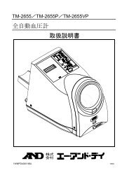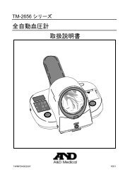
取扱説明書
取扱説明書
取扱説明書
- No tags were found...

You also want an ePaper? Increase the reach of your titles
YUMPU automatically turns print PDFs into web optimized ePapers that Google loves.
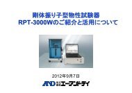
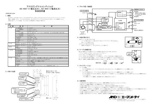
1WMPD4001355A1. 概 要アナログシグナルコンディショナAD-4541-V( 電 圧 出 力 )、AD-4541-I( 電 流 出 力 )取 扱 説 明 書AD-4541-V、AD-4541-I はロードセルやひずみゲージをセンサ 入 力 とするアナログシグナルコンディショナです。質 量 、 加 速 度 、 圧 力 、トルクなどの 信 号 を、PLC や PC のアナログ 入 力 に 合 わせて 信 号 レベルの 変 換 をします。本 体 は DIN レールへの 固 定 、ネジ 止 めによる 壁 面 等 への 固 定 が 可 能 です。2. 仕 様分 類 項 目 仕 様入 力 部 ゼロ 調 整 範 囲 ±0.5mV/Vスパン 調 整 範 囲 0.4mV/V~3.2mV/V非 直 線 性0.05% of F.S. typ.ロードセル 電 源 DC 5V 60mA max. (ロードセル 120Ω 系 1 個 、または350Ω 系 4 個 まで 使 用 可 能 )ゼロ 点 温 度 係 数 2μV/℃ typ.スパン 温 度 係 数 200ppm/℃ typ.周 波 数 特 性DC~ 約 2Hz(-3dB)応 答 時 間約 190ms (0%→90%)入 力 換 算 ノイズ 2μVp-p typ.校 正 値1mV/V ±0.2% typ.出 力 部 電 圧 出 力 (AD-4541-V) ±2V ( 負 荷 抵 抗 2kΩ 以 上 )電 流 出 力 (AD-4541-I) 4-20mA ( 負 荷 抵 抗 250Ω 以 下 )電 源 部 電 源 DC24V +10%-15%消 費 電 流100mA max( 約 2.4W)一 般 仕 様 使 用 温 度 範 囲 -5~+50℃使 用 湿 度 範 囲 85%RH 以 内 ( 結 露 不 可 )保 存 温 度 範 囲外 形 寸 法製 品 質 量-20~+70℃45W×122H×24D mm約 90gその 他 端 子 ばねクランプ 式 適 合 電 線 より 線 0.08~1.5mm 2 /AWG 28-14 最 大 被 覆 外 径 φ3.4mm3. 外 形 寸 法 図取 り 付 け 方 法DINレール 取 り 付 け または ネジによる 取 り 付 け本 体 材 質 PBT( 難 燃 V0、ガラス 繊 維 入 り 黒 色 )アイソレーション絶 縁 耐 圧入 出 力 - 電 源 間DC 500V 1 分 間付 属 品 端 子 台 操 作 用 マイナスドライバ ×1、 取 扱 説 明 書 ( 本 書 ) ×1センサ 入 力 端 子ゼロ 調 整 用ボリュームスパン 調 整 用ボリューム校 正 用 スイッチこのスイッチを 押 すと、 擬似 的 に 入 力 に 1mV/V が加 算 されます。アナログ 出 力 端 子および 電 源 端 子DIN レール 取 り 付 けバネ図 はAD-4541-V です。AD-4541-I も 同 一 寸 法 です。単 位 : mm4.ブロック 図 / 接 続 図センサ 入 力 端 子ロードセルまたはひずみゲージ5. 本 体 の 取 り 付 け• DIN レールに 取 り 付 ける 方 法ケース 下 端 の DIN レール 取 り 付 けバネをマイナスドライバ 等 で 引 き 出 し、DIN レールに 固 定 します。• ネジにより 取 り 付 ける 方 法四 隅 の 穴 を 使 用 して、ネジ 止 めすることも 可 能 です。6.ケーブル 接 続 方 法端 子 台 の 操 作 口 から 付 属 のドライバを 垂 直 に 突 き 当 たるまで 差 し 込 みます。(ドライバを 回 したりねじったりしないでください。)ドライバはしっかり 挿 入 されると 自 立 します。ドライバを 差 し 込 んだ 状 態 でケーブルを 挿 入 し、ドライバを 引 き 抜 くと 接 続 されます。ケーブルを 取 り 外 す 時 も 同 様 に、ドライバを 差 し 込 んだ 状 態 でケーブルを 引 き 抜 きます。端 子 台 へ 接 続 する 電 線 の 被 覆 のむき 長 は 5~6mm とし、 軽 く 捩 ってください。( 下 図 参 照 )5~6mm7.キャリブレーション(1)ゼロ 調 整センサを 無 負 荷 にして、アナログ 出 力 がゼロ 点 になるように、ゼロ 調 整 用 ボリュームで 調 整 します。(2)スパン 調 整センサに 負 荷 をかけ、アナログ 出 力 が 所 定 の 値 になるようにスパン 調 整 用 ボリュームで 調 整 します。センサに 負 荷 をかけられない 場 合 は、 校 正 用 スイッチを 使 用 して、 入 力 に 擬 似 的 に 1mV/V を 加 算 することにより 調 整 を 行 なうことも 可 能 です。(ゼロ 調 整 とスパン 調 整 は、 数 回 繰 り 返 すと 精 度 が 向 上 します。)8. 注 意 事 項入 力 シールド SHDEXC+SIG+電 線 の 処 理入 力 部LC 印 加 電 源DC 5V校 正 値 回 路1mV/Vオフセット/ゲイン調 整 回 路増 幅 回 路LPF電 源 部(アイソレーションあり)出 力 部レベル 変 換 回 路・±2V・4-20mA※ 機 種 によるドライバは垂 直 に 挿 入電 源 端 子 (DC24V)SIG-EXC-POWER-電 源 端 子 は2 個 ずつ 並 列 になっています。 渡 り 線 接 続にご 利 用 ください。POWER+アナログ 出 力 端 子OUT+電 圧 または 電 流 出 力• 本 体 の 取 り 付 けを 確 実 に 行 なうとともに、 振 動 や 衝 撃 がかからないようにしてください。• 端 子 台 への 電 線 の 接 続 は、 必 ず 電 源 を 切 ってから 行 ってください。• 内 部 に 異 物 が 混 入 しないようにしてください。 異 物 の 混 入 は 故 障 の 原 因 になります。• 電 線 の 接 続 、ボリューム・ 校 正 用 スイッチの 操 作 には、 付 属 品 のドライバを 使 用 してください。• ボリューム・ 校 正 用 スイッチの 操 作 時 、ドライバは 垂 直 に 挿 入 してください。 斜 めに 挿 入 すると 内 部 回 路 がショートする 可 能 性 があります。• ゼロ 調 整 用 とスパン 調 整 のボリュームの 有 効 回 転 数 は 15 回 転 です。 必 要 以 上 に 回 さないでください。• 分 解 、 改 造 は 行 なわないでください。 故 障 の 原 因 になります。• 結 露 、 水 没 させないでください。 使 用 時 、 保 管 時 とも 結 露 は 故 障 の 原 因 になります。SHD出 力 シールドOUT-本 社 〒170-0013 東 京 都 豊 島 区 東 池 袋 3-23-14 ダイハツ・ニッセイ 池 袋 ビルTEL.03-5391-6126 FAX.03-5391-6129
Analog Signal ConditionerAD-4541-V (Voltage output type), AD-4541-I (Current output type)Instruction Manual1WMPD4001355A1. OutlineAD-4541-V and AD-4541-I are analog signal conditioners utilizing a load cell or strain gauge as sensor input and converts signalssuch as mass, acceleration, pressure and torque at the signal level, to an output suitable for a PLC or PC analog input.The conditioners can be mounted on a DIN rail or on the wall.2. SpecificationsCategory Item DescriptionInput Zero adjustment range -0.5 mV/V to +0.5 mV/VSpan adjustment range 0.4 mV/V to 3.2 mV/VNon-linearity0.05% of F.S. typ.Loadcell excitation 5 VDC 60 mA max. (Can be used with one loadcell of 120Ω or maximum four loadcells of 350Ω )Zero temperature coefficientSpan temperature coefficientFrequency response2μV/°C RTI typ.200ppm/°C typ.DC to 2 Hz(-3dB)Response Approx. 190 ms (0% to 90%)Input noiseCalibration standard2μVp-p RTI typ.1 mV/V ±0.2% typ.Output Voltage output (AD-4541-V) -2 V to +2 V (Load 2kΩ or higher)Current output (AD-4541-I)4 mA to 20 mA (Load 250Ω or lower)Power Voltage 24 VDC +10%-15%CurrentGeneral Operating temperature -5°C to +50°COperating humidityStorage temperatureExternal dimensionsMass100 mA max (Approx. 2.4W)85%RH or lower (No condensation)-20°C to +70°C45W x 122H x 24D mmApprox. 90 gOthers Terminal Spring clamp typeWire 0.08 mm 2 to 1.5 mm 2 (AWG 28-14) Maximum outside diameter 3.4 mmInstallationDIN rail or screwMaterial (Body)PBT (V0)IsolationInput output to power supplyWithstanding voltage 500 VDC for 1 minAccessoriesFlathead screwdriver 1 pc, Instruction manual (this document) 1 pc3. External dimensionsSensor input terminalZero adjustmentcontrolSpan adjustmentcontrolCAL switchWhen pressed, a pseudovalue of 1mV/V is addedto the input.Analog output terminaland power terminalThe illustration below is the AD-4541-V.The size of the AD-4541-1 is the same asthe AD-4541-V.4. Block DiagramSensor inputLoadcellorstrain gauge5. Installation• Mounting on the DIN railUsing the accessory screwdriver, push out the DIN rail mounting spring located at thebottom of the casing and secure the casing on the DIN rail.• Using the screwsUsing the holes on four corners, the casing can be secured on the wall with the screws.6. Cable connectionCaution: Before cable connection, be sure to turn the power off.Insert the accessory screwdriver perpendicularly into the terminal block as shown in theillustration to the right, until stopped. At this time, do not rotate or twist the screwdriver.The screwdriver, when inserted firmly, stands alone.With the screwdriver inserted, insert the cable and pull out the screwdriver to connect the cable.To disconnect the cable, insert the screwdriver and pull out the cable.Remove the insulation from the cable tip to expose cables 5 to 6 mm long. Twist the cableslightly and connect to the terminal block. (See the illustration below.)5 to 6 mm7. CalibrationInput shield SHD(1) Zero adjustmentWith no load on the sensor, use the zero adjustment control to adjust the conditioner so that the analog output will be the zero point.(2) Span adjustmentWith load on the sensor, use the span adjustment control to adjust the conditioner so that the analog output will be the designated value.If no load is to be applied to the sensor, use the CAL switch to add a pseudo value of 1 mV/V to the input and make an adjustment.* Repeating the above adjustments several times will improve the accuracy.8. PrecautionsEXC+SIG+AmplifierCable treatmentInputLC excitation5 VDCStandard1 mV/VOffset/gainadjustmentLPFDC/DC converterWith isolationOutputLevel converter-2 to +2Vor4 to 20 mA*Depends on the modelPower 24 VDCSIG-EXC-POWER-Two sets of two terminalsin parallel. Use them forcrossover connection.POWER+Analog outputSHDOutput shieldOUT+Voltage or current output• Install the conditioner securely so that it is free from vibrations and impact.• Be sure to turn the power off before cable connection.• Keep the interior free of dust and foreign materials. They may cause the damage to the conditioner.• When connecting cables or operating the controls and CAL switch, use the accessory screwdriver.• When operating the controls and CAL switch, be sure to insert the screwdriver perpendicularly. Inserting the screwdriver with a tiltmay cause a short circuit.• The zero adjustment and span adjustment controls have a maximum number of revolutions of 15. Do not rotate them more thannecessary.• Do not disassemble or modify the conditioner. It may cause the damage to the conditioner.• Avoid condensation during operation and storage.• Do not immerse the conditioner in water.OUT-Insert thescrewdriverperpendicularlyDIN rail mounting springUnit: mm3-23-14 Higashi-Ikebukuro, Toshima-ku, Tokyo 170-0013 JAPANTelephone: [81] (3) 5391-6132 Fax: [81] (3) 5391-6148http://www.aandd.co.jp/