Determining shape and reflectance of Lambertian, specular, and ...
Determining shape and reflectance of Lambertian, specular, and ...
Determining shape and reflectance of Lambertian, specular, and ...
- No tags were found...

You also want an ePaper? Increase the reach of your titles
YUMPU automatically turns print PDFs into web optimized ePapers that Google loves.
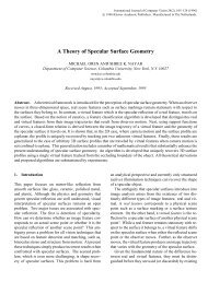
the object from a different direction. The entire array <strong>of</strong> extendedsources may be sequentially scanned such that, for each scan, a singlesource is active <strong>and</strong> an image <strong>of</strong> the object surface is obtained.We will confine the sampling process to two dimensions; the surfacenormal vector, viewing direction vector, <strong>and</strong> source direction vectorsfor all extended sources, are coplanar. The sequential scannin<strong>of</strong> extended sources positioned in the directions {Bi: i=1,2, ...... Mfresults in a set <strong>of</strong> image intensities {I’i: i=1,2, ...... M} measured ateach point on the object surface.I’Figure 5: Sampling the modified photometric function.The number <strong>of</strong> samples measured at each surface point isdetermined by the frequency f at which P(0,) is sampled. In order toextract the <strong>shape</strong> <strong>and</strong> <strong>reflectance</strong> parameters <strong>of</strong> hybrid surfaces, both<strong>Lambertian</strong> <strong>and</strong> <strong>specular</strong> components <strong>of</strong> image intensity must be detected.Since we have used a delta function for <strong>specular</strong> reflectionmodel, the period <strong>of</strong> the modified photometric function that contains<strong>specular</strong> intensities is equal to the width, 2a, <strong>of</strong> the extended sourceradiance function. In the following section, we will show that, ingeneral, at least two photometric samples must have non-zero <strong>specular</strong>intensities for the extraction technique to work. Hence, thephotometric function must be sampled at a frequency greater thanor equal to the minimum sampling frequency fmin. where:1f . =-.mmaNote that, at this minimum frequency, the radiance distributions <strong>of</strong>adjacent extended sources overlap each other for an interval <strong>of</strong> a.3 Extracting Shape <strong>and</strong> ReflectanceGiven the set <strong>of</strong> image intensities {I‘i} measured at a surface point,we want to determine the orientation 8, <strong>and</strong> <strong>reflectance</strong> parametersA’ <strong>and</strong> B’ <strong>of</strong> the point. We will first develop techniques to computeorientations <strong>of</strong> purely <strong>Lambertian</strong> <strong>and</strong> purely <strong>specular</strong> surfaces.Later, these techniques will be used as tools to extract orientations<strong>and</strong> <strong>reflectance</strong> parameters <strong>of</strong> hybrid surfaces.3.1 <strong>Lambertian</strong> SurfacesConsider the case where the surface <strong>of</strong> an object is known to bepurely <strong>Lambertian</strong>, <strong>and</strong> the <strong>shape</strong> <strong>of</strong> the object is to be determined.The photometric samples for a <strong>Lambertian</strong> surface point may bewritten as:ri = ~ ’ ~ ~ - s e,). ( e ~(15)We would like to compute the orientation 8. <strong>and</strong> the strength A’<strong>of</strong> <strong>Lambertian</strong> reflection component. To this end, an error E isformulated as the sum <strong>of</strong> the errors in measured samples over theentire set <strong>of</strong> samples:UE = [~’i - A‘ cos(8i - . (16)i=l’It is assumed that the interval <strong>of</strong> the modified photometric function that contains<strong>specular</strong> intensities is small compared to the total width <strong>of</strong> the photometricfunction. Therefore, sampling frequencies that ensure the detection <strong>of</strong> <strong>specular</strong>intensities will provide a sufficient number <strong>of</strong> Lambenian intensity samples.By using the conditions:we can determine values <strong>of</strong> 8, <strong>and</strong> A’ that minimize the error E.3.2 Specular SurfacesNow consider the case where the object surface is known to bepurely <strong>specular</strong>, <strong>and</strong> the <strong>shape</strong> <strong>of</strong> the object is to be determined.The photometric samples for a <strong>specular</strong> point may be written as:I‘~ = B’ ~(24,ei) .(18)We want to determine the orientation 8. <strong>and</strong> the <strong>specular</strong> strength B’from the intensity set {I’i}. Let us assume that the <strong>specular</strong> direction28, lies between the directions 8, <strong>and</strong> 8k+1 <strong>of</strong> two adjacent extendedsources. Further, let us assume that the photometric function is sampledusing the minimum frequency fmin, i.e. = 8k+ff. Therefore,since the surface is <strong>specular</strong> only the samples I‘k <strong>and</strong> I’k+1 will havenon-zero values. We see that when 8, increases, 28. approaches8~+1, I‘k decreases, <strong>and</strong> I’k+I increases. Similarly, when 8. decreases,28, approaches 8k, increases, <strong>and</strong> Pk+1 decreases. In fact, fromequation 18 we see that the intensity ratio z’k/I’k+1 is equal to the ratioL(28,, ek)/L(28,, 8k+1). Since the extended sources have decayingradiance functions (section 2.3). this ratio is a monotonic function <strong>of</strong>the angle 28,. Since the radiance functions <strong>of</strong> the extended sourcesare known a-priori, we can precompute <strong>and</strong> store in memory thecorrespondence between I‘k/I‘k+1 <strong>and</strong> 8,.Given the image intensity set {Pi} at a <strong>specular</strong> surface point,the non-zero image intensities in the set are first determined. If onlya single intensity value, for instance I’k, is greater than zero, thenwe know that 28, = 8k. If two image intensities, for instance I’k <strong>and</strong>I’k+I, are greater than zero, the ratio l‘k/I’k+] is used to determine 8,.Once 8, is found, B’ is obtained by using equation 18:1723.3 Hybrid SurfacesThe modified photometric function for hybrid surfaces is given byequation 13. At each surface point, we want to determine A‘, B’,<strong>and</strong> orientation 8, from the measured samples {I’i: i=1,2 ,...... M} <strong>of</strong>the photometric function. To this end, we will develop an algorithmthat attempts to separate the <strong>Lambertian</strong> <strong>and</strong> <strong>specular</strong> components 0feach measured image intensity, <strong>and</strong> computes surface orientations byusing the methods given above for <strong>Lambertian</strong> <strong>and</strong> <strong>specular</strong> surfaces.The extraction algorithm is based on two constraints, namely,the sampling frequency constraint <strong>and</strong> the unique orientation constraint.By sampling the modified photometric function at the minimumsampling frequency fmin, we can ensure that only two consecutiveimage intensities in the intensity set {[’,} contain non-zero<strong>specular</strong> components. For each k in the interval 0 < k < M, I’k <strong>and</strong>I’k+l are hypothesized as being the two intensities that are corruptedby <strong>specular</strong> components. All remaining intensities in the set {P,:i=1,2 ,...... M} must represent only <strong>Lambertian</strong> components <strong>of</strong> reflection.These intensities are used to compute the surface orientationOn] <strong>and</strong> the <strong>Lambertian</strong> strength A‘ (section 3.1). The <strong>Lambertian</strong>components IL’k <strong>and</strong> IL’k+l are determined <strong>and</strong> used to separate the<strong>specular</strong> components Is‘k <strong>and</strong> Is’k+I from I’k <strong>and</strong> I’k+l, respectively.The surface orientation e, <strong>and</strong> <strong>specular</strong> strength B’ are computedfrom Is‘k <strong>and</strong> Is’k+I (section 3.2).Next, the physical constraint that each surface point has aunique orientation is exploited. An estimate ea <strong>of</strong> the orientationis found as a weighted average <strong>of</strong> the orientations 0,l <strong>and</strong> OnS. Theweights are proportionate to the strengths <strong>of</strong> the two components <strong>of</strong>reflection. We support this method <strong>of</strong> weight selection because thesurface orientation that is computed from intensities resulting fromthe stronger <strong>of</strong> the two reflection components is less sensitive toimage noises <strong>and</strong> is, therefore, more reliable. An orientation errorek is found by comparing 8a with 8, <strong>and</strong> OnS. Using the aboveapproach, orientation errors are computed for all k, where 0 < k< M. The orientation <strong>and</strong> <strong>reflectance</strong> parameters computed for the