Determining shape and reflectance of Lambertian, specular, and ...
Determining shape and reflectance of Lambertian, specular, and ...
Determining shape and reflectance of Lambertian, specular, and ...
- No tags were found...

You also want an ePaper? Increase the reach of your titles
YUMPU automatically turns print PDFs into web optimized ePapers that Google loves.
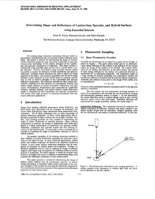
INTERNATIONAL WORKSHOP ON INDUSTRIAL APPLICATIONS OFMACHINE INTELLIGENCE AND VISION (MIV-891, Tokyo, April 10-12,1989<strong>Determining</strong> Shape <strong>and</strong> Reflectance <strong>of</strong> <strong>Lambertian</strong>, Specular, <strong>and</strong> Hybrid Surfacesusing Extended SourcesShree K. Nayar, Katsushi lkeuchi, <strong>and</strong> Takeo KanadeThe Robotics Institute, Camegie Mellon University, Pittsburgh, PA 15213AbstractAll existing <strong>shape</strong> extraction techniques that are based onphotometric measurements rely on assumed surface reflection properties.We present a method for determining the <strong>shape</strong> <strong>of</strong> surfaceswhose <strong>reflectance</strong> properties may vary from <strong>Lambertian</strong> to <strong>specular</strong>,without prior knowledge <strong>of</strong> the relative strengths <strong>of</strong> the <strong>Lambertian</strong><strong>and</strong> <strong>specular</strong> components <strong>of</strong> reflection. The object surface isilluminated using extended light sources <strong>and</strong> is viewed from a singledirection. Surface illumination using extended sources makesit possible to ensure the detection <strong>of</strong> both <strong>Lambertian</strong> <strong>and</strong> <strong>specular</strong>reflections. Multiple source directions are used to obtain an imagesequence <strong>of</strong> the object. An extraction algorithm uses the set <strong>of</strong> imageintensity values measured at each surface point to compute orientationas well as relative smngths <strong>of</strong> the <strong>Lambertian</strong> <strong>and</strong> <strong>specular</strong>reflection components. The proposed method has been named photometricsampling as it uses samples <strong>of</strong> a photometric function thatrelates image intensity to surface orientation, <strong>reflectance</strong>, <strong>and</strong> lightsource characteristics. Experiments’ were conducted on <strong>Lambertian</strong>surfaces, <strong>specular</strong> surfaces, <strong>and</strong> hybrid surfaces whose <strong>reflectance</strong>model is composed <strong>of</strong> both <strong>Lambertian</strong> <strong>and</strong> <strong>specular</strong> components.The results show high accuracy in measured orientations <strong>and</strong> estimated<strong>reflectance</strong> parameters.1 IntroductionShape from shading [4][6][9], photometric stereo [13][7][2], <strong>and</strong>local <strong>shape</strong> from <strong>specular</strong>ity [3] are examples <strong>of</strong> techniques thatextract three-dimensional <strong>shape</strong> information from photometric measurements.All <strong>of</strong> these techniques rely on prior knowledge <strong>of</strong>surface <strong>reflectance</strong> properties. In many vision applications, the <strong>reflectance</strong>properties <strong>of</strong> object surfaces are not readily available. Further,most existing methods are only capable <strong>of</strong> determining the<strong>shape</strong> <strong>of</strong> either <strong>Lambertian</strong> or <strong>specular</strong> surfaces. Many surfacesencountered in practice, are hybrid in <strong>reflectance</strong>; their <strong>reflectance</strong>model is a linear combination <strong>of</strong> <strong>Lambertian</strong> <strong>and</strong> <strong>specular</strong> models.Therefore, <strong>Lambertian</strong> <strong>and</strong> <strong>specular</strong> models are only limiting instances<strong>of</strong> the hybrid model. It is desirable to have a method that iscapable <strong>of</strong> extracting the <strong>shape</strong> <strong>of</strong> <strong>Lambertian</strong>, <strong>specular</strong>, as well ashybrid surfaces.Yet another limitation <strong>of</strong> all existing extraction methods istheir inability to furnish information regarding the <strong>reflectance</strong> properties<strong>of</strong> the object surface. In many industrial applications, surfacepolish <strong>and</strong> surface roughness are found to be important inspectioncriteria. In such cases, surface <strong>reflectance</strong> properties may be interpretedas measures <strong>of</strong> surface polish <strong>and</strong> roughness. Further, <strong>reflectance</strong>properties may be used to segment an image in differentregions; each region may be regarded as a different surface to aid theprocess <strong>of</strong> inspection. For these reasons, it would be <strong>of</strong> great valueto have a technique that could, in addition to determining <strong>shape</strong>, alsoestimate the <strong>reflectance</strong> properties <strong>of</strong> each surface point.This paper presents a method for determining the <strong>shape</strong> <strong>of</strong>objects whose surfaces may be <strong>Lambertian</strong>, <strong>specular</strong>, or hybrid.Shape information is extracted without prior knowledge <strong>of</strong> the relativestrengths <strong>of</strong> the <strong>Lambertian</strong> <strong>and</strong> <strong>specular</strong> reflection components.The method also determines parameters that represent the <strong>reflectance</strong>properties <strong>of</strong> each surface point.2 Photometric Sampling2.1 Basic Photometric FunctionConsider the illumination <strong>of</strong> an object by a point source <strong>of</strong> light, asshown in Figure 1. The point source emits light in all directions.Light energy reflected by the surface in the direction <strong>of</strong> the cameracauses an image <strong>of</strong> the surface to be formed. For a given orientation<strong>of</strong> the surface <strong>and</strong> direction <strong>of</strong> the point source, the amount<strong>of</strong> light energy reflected by the surface in a particular direction isdetermined by its <strong>reflectance</strong> properties. The <strong>reflectance</strong> model <strong>of</strong>a large number <strong>of</strong> surfaces comprises two components, namely, the<strong>Lambertian</strong> (diffuse) component <strong>and</strong> the <strong>specular</strong> (gloss) component.Therefore, the intensity at any point in the image <strong>of</strong> the surface maybe expressed as:I = IL+IS, (1)where IL is the <strong>Lambertian</strong> intensity component <strong>and</strong> IS is the <strong>specular</strong>intensity component.We will express the two components <strong>of</strong> image intensity interms <strong>of</strong> the parameters that describe the two-dimensional imaging<strong>and</strong> illumination geometry shown in Figure 1. In two dimensions,the source direction vectors, surface normal vector n, <strong>and</strong> viewingdirection vector v lie in the same plane. Therefore, directions arerepresented by a single parameter, namely, the zenith angle 8.<strong>Lambertian</strong> Reflection: The <strong>Lambertian</strong> intensity IL represents thediffuse component <strong>of</strong> reflection. Surfaces that satisfy Lambert’s lawappear equally bright from all directions. Broadly speaking, thereare two mechanisms that produce <strong>Lambertian</strong> reflection. In one case,ncamera UTFigure 1 : Two-dimensional illumination <strong>and</strong> imaging geometry. Asurface element with orientation 0, reflects light from the pointsource direction 0, into the camera.TH0250-1/89/0000-0169$01.00 0 1989 IEEE 169
light rays that impinge the surface are reflected many times betweensurface undulations before they are scattered into space. If thesemultiple reflections occur in a r<strong>and</strong>om manner, the incident energyis distributed in all directions resulting in diffuse reflection. Anothermechanism leading to diffuse reflection is the internal scattering <strong>of</strong>light rays. In this case, the light rays penetrate the surface <strong>and</strong> encountermicroscopic inhomogeneities in the surface medium. Thelight rays are repeatedly reflected <strong>and</strong> refracted at boundaries betweenregions <strong>of</strong> differing refractive indices. Some <strong>of</strong> the scatteredrays find their way back to the surface with a variety <strong>of</strong> directionsresulting in diffuse reflection. When diffuse reflection produced byeither or both <strong>of</strong> the above mechanisms results in constant surfaceradiance in all directions, we have <strong>Lambertian</strong> reflection. The brightness<strong>of</strong> a <strong>Lambertian</strong> surface is independent <strong>of</strong> the viewing direction.However, the brightness <strong>of</strong> a <strong>Lambertian</strong> surface is proportional tothe energy <strong>of</strong> incident light. As seen in Figure 1, the amount <strong>of</strong> lightenergy falling on the surface element is proportional to the area <strong>of</strong>the surface element as seen from the source position, <strong>of</strong>ten referredto as the foreshortened area. The foreshortened area is a cosine function<strong>of</strong> the angle between the surface orientation direction 6, <strong>and</strong> thesource direction 6,. Therefore the <strong>Lambertian</strong> intensity componentIL may be written as:IL = A ~os(e. - e,),(2)where the constant A determines the fraction <strong>of</strong> incident energy thatis diffusely reflected. We have assumed that the angle <strong>of</strong> incidence(6: - 6,) is greater than -TR <strong>and</strong> less than TR, i.e. IL is alwaysgreater than zero.Specular Reflection: Various <strong>specular</strong> <strong>reflectance</strong> models have beenproposed over the years. We will use the Beckmann <strong>and</strong> Spizzichinomodel [l] that is based physical optics theory. The surface height ismodeled as a continuous stationary r<strong>and</strong>om process with mean valuezero <strong>and</strong> st<strong>and</strong>ard deviation oh that represents the physical roughness<strong>of</strong> the surface. Maxwell’s equations are used to determine howincident light waves are scattered by the surface in various directions.Beckmann <strong>and</strong> Spizzichino have found <strong>specular</strong> reflection tobe composed <strong>of</strong> two primary components: the <strong>specular</strong> lobe component<strong>and</strong> the <strong>specular</strong> spike component. The lobe component spreadsaround the <strong>specular</strong> direction (e, = 28,). <strong>and</strong> the spike component iszero in all directions except a very narrow range around the <strong>specular</strong>direction. The strengths <strong>of</strong> the two components are dependent on theratio a,,/X, where X is the wavelength <strong>of</strong> incident light. When ah/Xz 0, the spike component is many orders in magnitude greater thanthe lobe component <strong>and</strong> the surface reflects light like a mirror. It isthe spike component that is responsible for strong highlights that are<strong>of</strong>ten observed on smooth surfaces. As “,+/A increases above unity,the spike component shrinks <strong>and</strong> the lobe component begins to dominatethe surface radiance value. In this paper, we will assume thatthe surface is smooth (ah/X < l.O), <strong>and</strong> the <strong>specular</strong> image intensityIS is solely determined by the spike component. Beckmann <strong>and</strong>Spizzichino have found that the spike component is mathematicallyrepresented by the square <strong>of</strong> a very sharp sinc function that tendsto be symmemc with respect to the <strong>specular</strong> angle 6, = 28,. Forsimplicity, we shall approximate the spike component by the deltafunction:The basic photometric function’ relates image intensity tosurface orientation, surface <strong>reflectance</strong>, <strong>and</strong> point source direction<strong>and</strong> may be written by substituting equations 2 <strong>and</strong> 3 in equation 1as:I = A cos(e, - e,) + B s(e, - 28,).(4)The constants A <strong>and</strong> B in equation 4 represent the relative strengths<strong>of</strong> the <strong>Lambertian</strong> <strong>and</strong> <strong>specular</strong> components <strong>of</strong> reflection. We call A<strong>and</strong> B the reflection parameters. We see that, A > 0 <strong>and</strong> B = 0 fora purely <strong>Lambertian</strong> surface, A = 0 <strong>and</strong> B > 0 for a purely <strong>specular</strong>surface, <strong>and</strong> A > 0 <strong>and</strong> B > 0 for a hybrid surface.Our objective is to determine orientation <strong>and</strong> <strong>reflectance</strong> ateach surface point from a set <strong>of</strong> image intensities that result fromchanging the source direction 8,. As seen in Figure 1, by movingthe source around the object, we can vary the source direction withoutchanging the orientation <strong>and</strong> <strong>reflectance</strong> parameters. Therefore,‘meIS = ~ 6(e, - 28,).photometric function is similar to the image irradiance [51 equation, sinceimage intensity is assumed to be Proportional to image irradiance,(3)even though the orientation <strong>and</strong> <strong>reflectance</strong> parameters are unknown,we can treat them as constants in equation 4. For this reason, wewill <strong>of</strong>ten refer to the basic photometric function as I(@:), a relationbetween image intensity <strong>and</strong> source direction. Figure 2 shows aplot <strong>of</strong> the basic photometric function for a hybrid surface <strong>of</strong> givenorientation.Figure 2: Basic photometric function [(e,) for a hybrid surface.2.2 Why Extended Sources ?We propose to illuminate the object surface by using extended sources.rather than point sources, for the following reasons:In the case <strong>of</strong> point source illumination, <strong>specular</strong> reflectionis not detected unless 6, = 26,. In order to determine <strong>shape</strong><strong>and</strong> <strong>reflectance</strong> parameters <strong>of</strong> <strong>specular</strong> <strong>and</strong> hybrid surfaces,<strong>specular</strong> reflections must be captured in the measured intensities.To detect <strong>specular</strong> reflections from surface points <strong>of</strong> allorientations, an infinite number <strong>of</strong> point ,sources need to bepositioned around the surface. Such an approach is unrealisticfrom the perspective <strong>of</strong> practical implementation. Unlike apoint source, an extended source emits light from an area <strong>of</strong>points rather than a single point. Therefore, a small number<strong>of</strong> extended sources may be used to ensure the detection <strong>of</strong><strong>specular</strong> reflections.In the case <strong>of</strong> point source illumination, image intensitiesdue to <strong>specular</strong> reflections are <strong>of</strong>ten observed to be muchgreater than intensities resulting from Lambextian reflections[lo]. Therefore, it is difficult to measure both components inthe same image. Extended source illumination tends to makethe image intensities due to <strong>Lambertian</strong> <strong>and</strong> <strong>specular</strong> reflectionscomparable to one another. A <strong>specular</strong> surface element<strong>of</strong> a given orientation will reflect light from a small area on theextended source into the camera. On the other h<strong>and</strong>, a Lambemansurface element <strong>of</strong> the same orientation reflects lightfrom all points on the extended source. This feature <strong>of</strong> theproposed illumination scheme makes it possible to measureboth <strong>Lambertian</strong> <strong>and</strong> <strong>specular</strong> reflections in the same image.2.3 Generating Extended SourcesThere are numerous ways <strong>of</strong> generating extended sources. In thissection, we present the approach that we have chosen to use. Anextended light source can be generated by illuminating a sheet <strong>of</strong>light-diffusing material with a point light source. Figure 3 illustratesthe illumination <strong>of</strong> a section <strong>of</strong> a circular diffuser <strong>of</strong> radius R. Thepoint source is placed at a distance H from the diffuser’s surface, <strong>and</strong>the viewed object is placed at the center <strong>of</strong> the circle. Let us assumethat the diffuser is “ideal”, i.e. incident energy is scattered equally inall directions. Therefore, the radiance’ L(6,0,) <strong>of</strong> the inner surface<strong>of</strong> the diffuser is proportional to the irradiance3 E(6, 0,) <strong>of</strong> the outersurface <strong>of</strong> the diffuser:L(8,8,) = CE(8, 8s). (5)2Radiance is defined as the flux emitted per unit foreshortened surface area perunit solid angle. Radiance is measured in watts per square meter per steradian(W.m-2.sr-’).’Irradiance is defined as the incident flux density <strong>and</strong> is measured in watts persquare meter (W.nr2).4Radiant Intensity <strong>of</strong> a source is defined as the flux exiting per unit solid angle<strong>and</strong> is measured in watts per steradian (Wsr-l).170
nCamera II*PointFurceExtended Source Radiance*Basic Photometric Function'TI1ILObjectFigure 3: An extended source.IDiffuserI'I YIWtIAwhere C is a constant <strong>of</strong> proportionality. The analytic expressionfor the surface irradiance E(8,8,) may be derived from the basics <strong>of</strong>radiometry as:IcosdE(8,8,) = -(6)where I is the radiant intensity4 <strong>of</strong> the point source S. The radiance <strong>of</strong>the extended source may be determined by expressing the variablesr <strong>and</strong> 4 in equation 6 in terms <strong>of</strong> tlie parameters R, H, <strong>and</strong> 8, <strong>of</strong> theillumination geometry:CI[(R + Wcos(6' - 8,) - RIL(8' ") = [(R + H - Rcos(8 - e,))* + (Rsin(8 - 8,))213/2'Throughout this paper, the position <strong>of</strong> an extended sourcewill be denoted by the angle <strong>of</strong> the point source used to generatethe extended source. The radiance function L(8,8,) is symmetric, oreven, with respect to the source direction (8 = 8,), <strong>and</strong> its magnitudedecreases as 8 deviates from 8,. Points on the diffuser that lie in theinterval 4-0. < 8 < 8,+a receive light from the point source S. Pointsthat lie outside this interval are occluded from the point source bypoints that lie in the interval. Thus, L(8,8,) = 0 for 8 < 8,-a <strong>and</strong> 8> &+cy. The source termination angle a is found from Figure 3 as:r2R(Y = cos-'-R+H'2.4 Photometric Function for Extended SourcesThe photometric function for point source ilIumination (equation 4)needs to be modified for extended source illumination. An extendedsource may be thought <strong>of</strong> as a collection <strong>of</strong> point sources whereeach point source has a radiant intensity that is dependent on itsposition on the extended source. The intensity <strong>of</strong> light reflected bya surface may be determined by computing the integral <strong>of</strong> the lightenergies reflected from all points on the extended source. Therefore,the modified photometric function ['(e,) is determined by convolvingthe basic photometric function I(@ with the extended source radiancefunction L(8,4). This operation is illustrated in Figure 4. For asurface point <strong>of</strong> orientation 4, the <strong>Lambertian</strong> component IL' <strong>of</strong> themodified photometric function is determined as:The limits <strong>of</strong> the integral are determined by the width <strong>of</strong> the extendedsource. It can be proved [8] that IL' is a cosine function <strong>of</strong> the anglebetween the surface orientation <strong>and</strong> the direction corresponding to(7 1(9)Figure 4: The photomemc function for extended source illuminationis obtained by convolving the basic photometric function with theextended source radiance function.the "center <strong>of</strong> mass" <strong>of</strong> the extended source radiance distribution,L(8,8,). In our case, since the extended source is symmetric withrespect to the direction 4, the center <strong>of</strong> mass <strong>of</strong> the radiance functionis in the direction 8,. Therefore, we obtain:IL' = A' cos(8, - e,), (10)where the constant A' represents the strength <strong>of</strong> the Lambeman component.On similar lines, the <strong>specular</strong> intensity component IS' resultingfrom the extended source L(8,8,) is determined as:8,+aIS' = B /8,-a L(8,8,) 6(8 - 28,) d8 , (11)or:IS' = B L(~o., e,) . (12)Strictly speaking, the result <strong>of</strong> the above integral is dependent onthe exact <strong>shape</strong> <strong>of</strong> the <strong>specular</strong> spike. However, since the spikecomponent is significant only in the <strong>specular</strong> direction, 28,. it isreasonable to assume that the <strong>specular</strong> intensity IS' is proportionalto L(28,,8,), while the constant <strong>of</strong> proportionality is dependent onthe exact <strong>shape</strong> <strong>of</strong> the spike. To this end, we will use the constantB', rather than B, to represent the strength <strong>of</strong> the <strong>specular</strong> component<strong>of</strong> the photometric function.The modified photometric function relates image intensity I'to extended source direction Br, <strong>and</strong> is expressed as the sum <strong>of</strong> thecomponents IL' <strong>and</strong> IS':2.5 SamplingI' = A' cos(e, - 0,) + B' ~(24,,e,) . (13)The process <strong>of</strong> measuring image intensities corresponding to differentsource directions is equivalent to sampling the modified photometricfunction If(&), as shown in Figure 5. Samples <strong>of</strong> the photometricfunction may be obtained by moving an extended sourcearound the object <strong>and</strong> taking images <strong>of</strong> the object for different sourcepositions. An alternative approach would be to distribute an array <strong>of</strong>extended sources around the object such that each source illuminates171
the object from a different direction. The entire array <strong>of</strong> extendedsources may be sequentially scanned such that, for each scan, a singlesource is active <strong>and</strong> an image <strong>of</strong> the object surface is obtained.We will confine the sampling process to two dimensions; the surfacenormal vector, viewing direction vector, <strong>and</strong> source direction vectorsfor all extended sources, are coplanar. The sequential scannin<strong>of</strong> extended sources positioned in the directions {Bi: i=1,2, ...... Mfresults in a set <strong>of</strong> image intensities {I’i: i=1,2, ...... M} measured ateach point on the object surface.I’Figure 5: Sampling the modified photometric function.The number <strong>of</strong> samples measured at each surface point isdetermined by the frequency f at which P(0,) is sampled. In order toextract the <strong>shape</strong> <strong>and</strong> <strong>reflectance</strong> parameters <strong>of</strong> hybrid surfaces, both<strong>Lambertian</strong> <strong>and</strong> <strong>specular</strong> components <strong>of</strong> image intensity must be detected.Since we have used a delta function for <strong>specular</strong> reflectionmodel, the period <strong>of</strong> the modified photometric function that contains<strong>specular</strong> intensities is equal to the width, 2a, <strong>of</strong> the extended sourceradiance function. In the following section, we will show that, ingeneral, at least two photometric samples must have non-zero <strong>specular</strong>intensities for the extraction technique to work. Hence, thephotometric function must be sampled at a frequency greater thanor equal to the minimum sampling frequency fmin. where:1f . =-.mmaNote that, at this minimum frequency, the radiance distributions <strong>of</strong>adjacent extended sources overlap each other for an interval <strong>of</strong> a.3 Extracting Shape <strong>and</strong> ReflectanceGiven the set <strong>of</strong> image intensities {I‘i} measured at a surface point,we want to determine the orientation 8, <strong>and</strong> <strong>reflectance</strong> parametersA’ <strong>and</strong> B’ <strong>of</strong> the point. We will first develop techniques to computeorientations <strong>of</strong> purely <strong>Lambertian</strong> <strong>and</strong> purely <strong>specular</strong> surfaces.Later, these techniques will be used as tools to extract orientations<strong>and</strong> <strong>reflectance</strong> parameters <strong>of</strong> hybrid surfaces.3.1 <strong>Lambertian</strong> SurfacesConsider the case where the surface <strong>of</strong> an object is known to bepurely <strong>Lambertian</strong>, <strong>and</strong> the <strong>shape</strong> <strong>of</strong> the object is to be determined.The photometric samples for a <strong>Lambertian</strong> surface point may bewritten as:ri = ~ ’ ~ ~ - s e,). ( e ~(15)We would like to compute the orientation 8. <strong>and</strong> the strength A’<strong>of</strong> <strong>Lambertian</strong> reflection component. To this end, an error E isformulated as the sum <strong>of</strong> the errors in measured samples over theentire set <strong>of</strong> samples:UE = [~’i - A‘ cos(8i - . (16)i=l’It is assumed that the interval <strong>of</strong> the modified photometric function that contains<strong>specular</strong> intensities is small compared to the total width <strong>of</strong> the photometricfunction. Therefore, sampling frequencies that ensure the detection <strong>of</strong> <strong>specular</strong>intensities will provide a sufficient number <strong>of</strong> Lambenian intensity samples.By using the conditions:we can determine values <strong>of</strong> 8, <strong>and</strong> A’ that minimize the error E.3.2 Specular SurfacesNow consider the case where the object surface is known to bepurely <strong>specular</strong>, <strong>and</strong> the <strong>shape</strong> <strong>of</strong> the object is to be determined.The photometric samples for a <strong>specular</strong> point may be written as:I‘~ = B’ ~(24,ei) .(18)We want to determine the orientation 8. <strong>and</strong> the <strong>specular</strong> strength B’from the intensity set {I’i}. Let us assume that the <strong>specular</strong> direction28, lies between the directions 8, <strong>and</strong> 8k+1 <strong>of</strong> two adjacent extendedsources. Further, let us assume that the photometric function is sampledusing the minimum frequency fmin, i.e. = 8k+ff. Therefore,since the surface is <strong>specular</strong> only the samples I‘k <strong>and</strong> I’k+1 will havenon-zero values. We see that when 8, increases, 28. approaches8~+1, I‘k decreases, <strong>and</strong> I’k+I increases. Similarly, when 8. decreases,28, approaches 8k, increases, <strong>and</strong> Pk+1 decreases. In fact, fromequation 18 we see that the intensity ratio z’k/I’k+1 is equal to the ratioL(28,, ek)/L(28,, 8k+1). Since the extended sources have decayingradiance functions (section 2.3). this ratio is a monotonic function <strong>of</strong>the angle 28,. Since the radiance functions <strong>of</strong> the extended sourcesare known a-priori, we can precompute <strong>and</strong> store in memory thecorrespondence between I‘k/I‘k+1 <strong>and</strong> 8,.Given the image intensity set {Pi} at a <strong>specular</strong> surface point,the non-zero image intensities in the set are first determined. If onlya single intensity value, for instance I’k, is greater than zero, thenwe know that 28, = 8k. If two image intensities, for instance I’k <strong>and</strong>I’k+I, are greater than zero, the ratio l‘k/I’k+] is used to determine 8,.Once 8, is found, B’ is obtained by using equation 18:1723.3 Hybrid SurfacesThe modified photometric function for hybrid surfaces is given byequation 13. At each surface point, we want to determine A‘, B’,<strong>and</strong> orientation 8, from the measured samples {I’i: i=1,2 ,...... M} <strong>of</strong>the photometric function. To this end, we will develop an algorithmthat attempts to separate the <strong>Lambertian</strong> <strong>and</strong> <strong>specular</strong> components 0feach measured image intensity, <strong>and</strong> computes surface orientations byusing the methods given above for <strong>Lambertian</strong> <strong>and</strong> <strong>specular</strong> surfaces.The extraction algorithm is based on two constraints, namely,the sampling frequency constraint <strong>and</strong> the unique orientation constraint.By sampling the modified photometric function at the minimumsampling frequency fmin, we can ensure that only two consecutiveimage intensities in the intensity set {[’,} contain non-zero<strong>specular</strong> components. For each k in the interval 0 < k < M, I’k <strong>and</strong>I’k+l are hypothesized as being the two intensities that are corruptedby <strong>specular</strong> components. All remaining intensities in the set {P,:i=1,2 ,...... M} must represent only <strong>Lambertian</strong> components <strong>of</strong> reflection.These intensities are used to compute the surface orientationOn] <strong>and</strong> the <strong>Lambertian</strong> strength A‘ (section 3.1). The <strong>Lambertian</strong>components IL’k <strong>and</strong> IL’k+l are determined <strong>and</strong> used to separate the<strong>specular</strong> components Is‘k <strong>and</strong> Is’k+I from I’k <strong>and</strong> I’k+l, respectively.The surface orientation e, <strong>and</strong> <strong>specular</strong> strength B’ are computedfrom Is‘k <strong>and</strong> Is’k+I (section 3.2).Next, the physical constraint that each surface point has aunique orientation is exploited. An estimate ea <strong>of</strong> the orientationis found as a weighted average <strong>of</strong> the orientations 0,l <strong>and</strong> OnS. Theweights are proportionate to the strengths <strong>of</strong> the two components <strong>of</strong>reflection. We support this method <strong>of</strong> weight selection because thesurface orientation that is computed from intensities resulting fromthe stronger <strong>of</strong> the two reflection components is less sensitive toimage noises <strong>and</strong> is, therefore, more reliable. An orientation errorek is found by comparing 8a with 8, <strong>and</strong> OnS. Using the aboveapproach, orientation errors are computed for all k, where 0 < k< M. The orientation <strong>and</strong> <strong>reflectance</strong> parameters computed for the
: ,..., ,.I