Cellular Network Planning and Optimization Part V: GSM
Cellular Network Planning and Optimization Part V: GSM
Cellular Network Planning and Optimization Part V: GSM

Create successful ePaper yourself
Turn your PDF publications into a flip-book with our unique Google optimized e-Paper software.
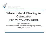
<strong>Cellular</strong> <strong>Network</strong> <strong>Planning</strong><strong>and</strong> <strong>Optimization</strong><strong>Part</strong> V: <strong>GSM</strong>Jyri Hämäläinen,Communications <strong>and</strong> <strong>Network</strong>ing Department,TKK, 18.1.2008
<strong>GSM</strong> Briefly2
General <strong>GSM</strong> was the first digital cellular system. <strong>GSM</strong> was launched in 1992Over 2 billion subscribers worldwideOver 600 million subscribers in Europe Conventional <strong>GSM</strong> voice is Circuit Switched (CS)Call occupies the channel during the duration of th e call The latest st<strong>and</strong>ard phase includesGeneral Packet Radio Service (GPRS)Enhanced Data Rates for <strong>GSM</strong> (EDGE)GPRS <strong>and</strong> EDGE are packet switched systems3
<strong>GSM</strong> Spectrum Originally <strong>GSM</strong> operated only in 900 MHz b<strong>and</strong> Later extended to 1800 MHz <strong>and</strong> 1900 MHz b<strong>and</strong>s Most <strong>GSM</strong> networks operate in the 900 MHz or 1800MHz b<strong>and</strong>s Also 450MHz b<strong>and</strong> is used in some countries Spectrum example In so-called primary <strong>GSM</strong> 900 MHz the uplinkfrequency b<strong>and</strong> is 890–915 MHz, <strong>and</strong> the downlinkfrequency b<strong>and</strong> is 935–960 MHz. This 25 MHz b<strong>and</strong>width is subdivided into 124 carrie rfrequency channels, each spaced 200 kHz apart.4
<strong>GSM</strong> System architectureOur main focus area5
Base Station Subsystem (BSS) Base Transceiver Station (BTS) Radio interface control between BTS <strong>and</strong> MS Transmission execution, channel encryption, diversity,frequency hopping Base Station Controller (BSC) H<strong>and</strong>over control, channel assignments, collection o fcell configuration data etc6
<strong>Network</strong> Switching System (NSS)Mobile Switching Center (MSC)Call switching; MSC control calls between BSS <strong>and</strong> o ther networks(PSTN, PLMN)Gateway MSC (GMSC)Executes gateway functions for MSCHome Location Register (HLR)Database that contains information of operators own subscribers.Visitor Location Register (VLR)Database that contains information of visiting subs cribers. There isone VLR per MSCServing GPRS Support Node (SGSN)H<strong>and</strong>les packet data from GPRS/EDGEGateway GPRS Support Node (GGSN)Gateway functions for SGSN7
<strong>GSM</strong> Frame structure Time Division Multiplexing (TDMA) is used8 full-rate or 16 half-rate speech channels per 200 kHzchannel. There are eight radio timeslots within a r adioframe.Half rate channels use alternate frames in the sametimeslot. The channel data rate is 270.833 kbit/s, a nd theframe duration is 4.615 ms TDMA/FDMA schemeOn top of this frame structure there is multiframe,superframe <strong>and</strong> hyperframe structures.0 1 2 3 4 5 6 7200kHz4.615ms8
Logical channel structure<strong>GSM</strong> channelsTraffic channels (TCH)Signaling channelsBCCH(broadcast ch)DCCH(dedicated ctrl ch)Full rateHalf rateDLCCCH(common ctrl ch)DL UL slow fastTCH/FTCH/HFCCH SCH PCH AGCH RACH SACCHSDCCH9FACCH
Channel structure Traffic channels (our focus is in speech service) Full rate: 9.6 kbps for speech (1 time slot/radio frame ) Half rate: 4.8 kbps for speech (1 time slot inalternating radio frames) BCCH Provides general cell specific information MS can register to cell only if it can detect BCCHFrom our perspective TCH <strong>and</strong> BCCH are most important.10
Channel structure FCCH = Frequency correction channel SCH = Synchronization channel PCH = Paging channel AGCH = Access grant channel RACH = R<strong>and</strong>om access channel SACCH = Slow assosiated control channel SDCCH = St<strong>and</strong>-alone dedicate control channel FACCH = Fast assosiated control channel11
<strong>Network</strong> planning issues in <strong>GSM</strong>12
Frequency reuse Cluster sizes up to K=12 or even more are used insome extreme cases. Due to increasing traffic cluster sizes tend to decrease =>replanning <strong>and</strong> optimization of present networks is ongoingactivity Cluster size K=1 is not used due to high co-channelinterference BCCH <strong>and</strong> TCH may have different cluster sizes BCCH is crucial for connection => larger cluster sizes13
Frequency reuse rateFrequency reuseMeasure for effectiveness of frequency planTrade-off: Effectiveness vs interference Multiple re-use rates increase effectiveness of fre quencyplanCluster sizeCompromise between safe, interference free planning <strong>and</strong>effective resource usage1 3 6 9 12 15 18 21same frequencyin every celltight re-use planningnormal planning(TCH macro layer)safe planning(BCCH layer)14
TRXA transmission/reception facility is called as a tr ansceiver (TRX).Typically, a cell has several TRXs, <strong>and</strong> one frequen cy is allocated toeach TRX. The capacity of a cell can therefore be measured in thenumber of TRXs.A time slot that carries user traffic is also calle d as Traffic Channel(TCH).For user speech service 1 time slot/radio frame is reserved in TCH/F<strong>and</strong> 1 time slot in alternating radio frames in TCH/HFor administrative purposes, e.g. providing mobile terminals withcontrol information, there is also one BCCH in each cell.This channel consumes one time slot (slot #0), <strong>and</strong> is operated by oneTRX in each cell.In physical BCCH there are at least FCCH <strong>and</strong> SCH + basic systemrelated information15
SINR <strong>and</strong> TX powersAccording to <strong>GSM</strong> specifications C/I > 9dB for nominal performance.C/I = carrier to interference power ratio Here interference termcontains also AWGN.MS transmission powerIn <strong>GSM</strong>850/900 TX power is between 0.8W <strong>and</strong> 8W. Usua l valueis 2W = 33dBmIn <strong>GSM</strong>1800/1900 TX power is between 0.25W <strong>and</strong> 4WBS transmission powerIn <strong>GSM</strong>-900 <strong>and</strong> 1800 TX normal BTS (= macro BTS) power isusually between 5W <strong>and</strong> 40W = 46 dBm.Output powers in micro BTS’s are between 14dBm <strong>and</strong> 32dBmFor macro BTS power is measured in combiner inputFor micro BTS power is measured in antenna connecto r16
Assume thatExample Operator has 5 MHz available for <strong>GSM</strong> Operator makes the TCH frequency plan according tospecifications (SINR > 9dB) but add 6dB marginal forBCCH SINR. Propagation exponent is 4, system is interferencelimited Problems What are the cluster sizes for BCCH <strong>and</strong> TCH? How many TRX’s are needed What is the number of TCH/F <strong>and</strong> TCH/H speechchannels per cell?17
Solution 5 MHz/200kHz = 25 subcarriers, 8 time slots ineach => 200 time slots in total SINR for TCH = 9dB => Γ=7.943 SINR for BCCH = 15dB => Γ=7.943 Propagation exponent α = 4 => C(α) ~ 7 Interference limited system => we can useequation= 7.943 (TCH) After solving K for TCH we find that K=2.4855 Similarly we find for BCCH that K=4.95918
SolutionClosest cluster sizes from For TCH cluster size = 3 For BCCH cluster size = 7One TRX can h<strong>and</strong>le 1 subcarrier (200 kHz) We need 1 BCCH-TRX/cell K=7 for BCCH => 7 subcarriers needed for BCCH There are 18 subcarriers left for TCH. Since K=3 for TCH we need 6TRX/cell in addition to the one that is carrying BCCH In total we need 7 TRX/cellNumber of speech channelsTCH TRX’s: 7x8 speech channels for full rate <strong>and</strong> 7x16 f or half rateBCCH-TRX: 7 speech channels for full rate <strong>and</strong> 14 speech channelsfor half rateIn total there will be 63 speech channels for full rate <strong>and</strong> 126 for halfrate.This is about the maximum capacity configuration for the operator19
Sectorizing <strong>and</strong> range Three-sector sites are most common in <strong>GSM</strong>Sectorization gives antenna gain in BS Maximum cell size is round 35 km Cell size depends on the timing advance which is 232.47 µsin basic <strong>GSM</strong> systemUsually cell sizes are between few hundreds meters to fewkilometers. Very large cells may occur e.g. in sea coastswhere bunch of isl<strong>and</strong>s are covered by a single BS.20
Cell categories Commonly used cell categories Macro cell = cell where the base station antenna isinstalled on a mast or a building above average roo ftop level. Macro cells are common in all outdoorenvironments Micro cell = cell where antenna is placed under rooftop level. Micro cells are used in urban areas to c overfew blocks of buildings Pico cell = cell that admit coverage of some tens ofmeters (coverage can vary depending on theenvironment). Used indoors.21
Indoor coverageUsually cheapest <strong>and</strong> most common way to provide indoor coverageis to use outdoor macro base stations for this purpose= outdoor to indoor coverage.Indoor users on the cell edge usually define the cell size sincepenetration loss due to buiding walls can be tens of decibels (usualvalue for penetration loss is 20dB)Indoor coverage may be provided also by indoor pico base stations.Suitable in office buildings; each floor can be covered by few picobase stationsThe large number of base stations may increase the network costsRadio repeaters <strong>and</strong> RF heads provide an other solutionIn repeater distributed antennas (e.g. antenna/floor) are fed throughpower splittersRepeater system applies an outdoor antenna that receives theoutdoor BS signal after which the system repeates the signal fromindoor antennas.22
Frequency hopping (FH) in <strong>GSM</strong> FH means that a TRX shifts frequency at every newradio frame => hopping is performed approximately 1/(4.615*0.00 1) =217 times per second.For a specific user, a new frequency is used from o ne timeslot to the next. The advantages of FH are twofoldFrequency diversityInterference diversity. The drawback with FH is that the network componentsbecome more complex <strong>and</strong> expensive.23
FH diversity gain Transmitted signal is subject to fast fading due tomultipath nature of the propagation. Especially, if the receiver is moving, the user wil lexperience fading dips frequently, <strong>and</strong> the distancebetween the fading dips depends on the frequency us ed. Changing frequency continuously is one way to reduc ethe influence of fading dips <strong>and</strong> the probability of goodlink quality is increased. The advantage of using F H isthat the channel will usually not suffer severe fad ing dipsunder longer time periods. The number of hopping frequencies is an importantfactor that affects the frequency diversity gain. H ighergain is achieved with more hopping frequencies, butmore than 8 hopping frequencies give less improveme nt24
FH diversity gainChannel power response is goodChannel power response is bad0 1 2 3 4 5 6 7Frequency 2 after a hopFrequency 10 1 2Channel bits from consecutive slots are mixed (interleaving in TX unit<strong>and</strong> deinterleaving in RX unit) => fading is averaged a nd detection hasbetter probability to be successfull25
FH interference diversity gainWithout FH, neighboring cells with co-channel frequ encies to thecarrier frequency will interfere continuously.The interference can be severe for certain frequenc ies <strong>and</strong> may leadto information loss.FH means that different frequencies will interfere with the carrier atdifferent time slots.Instead of having a constant level of interference between two cells,the interference is spread among several frequencie s.For a specific carrier, only some time slots will s uffer from highinterference. From a system point of view, strong i nterferers areshared between users <strong>and</strong> so called interference ave raging isachieved.A <strong>GSM</strong> network can be planned for average interferen ce instead ofworst case interference.The interference diversity gain is dependent on the number of hoppingfrequencies <strong>and</strong> interference levels from the interf ering cells. Asignificant interference diversity gain is obtained with as little as 3hopping frequencies.26
FH StrategiesCyclic FHIn cyclic hopping, all interfering cells use the sa me hopping sequence,<strong>and</strong> a channel will be affected by the same interfer ers all the time. Nointerference diversity is obtained with cyclic hopp ing.R<strong>and</strong>om FHR<strong>and</strong>om hopping uses sequences that are pseudo-r<strong>and</strong>o mlygenerated => interference diversity is obtained.The physical ways to perform FH in a cell are baseb <strong>and</strong> hopping <strong>and</strong>synthesized hopping.In baseb<strong>and</strong> hopping, every TRX is assigned to a fix ed frequency,while the channel is shifted between the TRXs. The number offrequency carriers must be equal to the number of T RXs.In synthesized hopping, channel stays at a certain TRX, while the TRXshifts among the available frequencies. In the latt er method, thenumber of carriers is greater than or equal to the number of TRXs.Since the number of frequencies can be more than th e number oftransceivers in a cell when synthesized hopping is used, the reusefactor can be changed while the number of TRXs is fi xed.27
FH Strategies There are two strategies for using the frequency ba nd forthe TCH <strong>and</strong> BCCH carriersIn common b<strong>and</strong> strategy both TCH <strong>and</strong> BCCH carriers usethe entire b<strong>and</strong>, <strong>and</strong> a TCH can receive interference fromboth TCH <strong>and</strong> BCCH carriers.In dedicated b<strong>and</strong> strategy the frequency b<strong>and</strong> is split intotwo parts, one for the TCH frequencies <strong>and</strong> one for theBCCH frequencies. In this strategy a TCH carrier ca n onlybe interfered by another TCH. FH is not performed a t theTRXs that operate the BCCH.Simulations have shown that dedicated spectrum b<strong>and</strong> sgive less interference than common b<strong>and</strong> strategy wh ichsuffered from severe disturbance in the downlink. I t is easierto put extra TCH-TRX in an existing cell when dedic atedb<strong>and</strong>s are used since the BCCH frequency plan does n othave to be changed.28
Frequency assignment problem Classical frequency assignment problem (FAP) belong sto the class of NP-complete problems, which means thatthe problem probably can not be solved in polynomia ltime. There exist two major approaches to deal with the F APin wireless networksFixed Channel Assignment (FCA). In FCA, a channel isassigned to a connection beforeh<strong>and</strong> <strong>and</strong> can not bechanged on-line.Dynamic Channel Assignment (DCA). In DCA thechannels are changed on-line whenever the radioconnection suffers from interference <strong>and</strong> the qualit yrequirements are not fulfilled.29
FCA vs DCA Fixed Channel Allocation (FCA)This is conventional approach where each cell is al located to apredetermined set of channels. Channels are allocat edaccording to frequency planRadio resources (channels) can’t be transferred bet ween cells<strong>and</strong> network planning is usually done on ‘worst case ’ basis =>trunking loss since traffic load changes. Dynamic Channel Allocation (DCA)Channels are not allocated permanently to different cells butBS allocates channels dynamically to coming calls.DCA applies algorithm that take into account e.g. Likelihood of blocking, co-channel interference, ot her costfunctionsIn extreme case all channels are available in each cell <strong>and</strong>DCA eliminates the need for frequency planningRadio resource reuse is changing dynamically => hig hertrunking efficiency30
Frequency assignment problem in FCA There exist several versions of FCA approachMinimum span FAP. In the minimum span FAP, certain soft<strong>and</strong>/or hard restrictions are given for the quality of the network.These restrictions can be interference <strong>and</strong> separati onrequirements. The soft restrictions can be violated at somepenalty cost, but the hard restrictions must be met . Theobjective is to minimize the difference between the minimum<strong>and</strong> maximum frequencies assigned, the span.Minimum order FAP. Instead of minimizing the span offrequencies, the number of frequencies is minimized inminimum order FAP.Minimum blocking FAP. The minimum blocking <strong>and</strong> minimuminterference FAP (see below) use a fixed span of fr equencies.In the minimum blocking FAP, the goal is to assign frequenciesin such a way that the overall blocking probability of thenetwork is minimized.Minimum interference FAP. The objective is to minimize thetotal sum of interference in the network.31
Frequency assignment problem in DCA All or almost all frequencies are available ineach cell Very general optimization problem faced Like in FCA related FPA different approaches can beadopted (starting from blocking, interference or othermeasures) The information change between base stations is slow=> fast interference mitigation is difficult Slow interference avoidance methods can be designedbased on interference matrices. Different companies have their own solutions32
Simplified link budgets33
Background information RX sensitivity (3GPP TS 05.05 V8.20.0 (2005-11))<strong>GSM</strong> 900 MS: for <strong>GSM</strong> 900 small MS -102 dBm<strong>GSM</strong> 900 BTS for normal BTS -104 dBm for micro BTS from -87 down to -97 dBm depending on t he BTSclass For pico BTS -88 dBmDCS 1 800 MS for DCS 1 800 MS -102 dBm (for some classes also -100 d Bm)DCS 1 800 BTS for normal BTS -104 dBm for micro BTS from -92dBm down to -102 dBm depending on theclass for pico BTS -95 dBmNote: RX sensitivity is the the minimum received pow er forwhich the predefined SNR requirement is achieved.34
Recall: SINR <strong>and</strong> TX powersAccording to <strong>GSM</strong> specifications C/I > 9dB for nominal performance.C/I = carrier to interference power ratio Here interference termcontains also AWGN.MS transmission powerIn <strong>GSM</strong>850/900 TX power is between 0.8W <strong>and</strong> 8W. Usua l valueis 2W = 33dBmIn <strong>GSM</strong>1800/1900 TX power is between 0.25W <strong>and</strong> 4WBS transmission powerIn <strong>GSM</strong>-900 <strong>and</strong> 1800 TX normal BTS (= macro BTS) power isusually between 5W <strong>and</strong> 40W = 46 dBm.Output powers in micro BTS’s are between 14dBm <strong>and</strong> 32dBmFor macro BTS power is measured in combiner inputFor micro BTS power is measured in antenna connecto r35
Simple UL link budget: Illustrative exampleAntennagain = 16 dBiFeeder/cableloss = 4 dB- 100 dBmDiversity gain (2 antennas) = 3 dB- 116 dBmPath loss = 152 dB- 104 dBm33 dBmTX PowerRX Sensitivity33 dBm (2W)-104 dB Antenna gain is a design issue, usually16-18dBi when 3 sectors (cells) in site.RX sensitivity is also design issue butphysics <strong>and</strong> costs put limits to it.Neither interference nor shadow fading 36is taken into account here
Simple DL link budget: Illustrative example34 dBmAntenna gain = 16dBi (no diversity)50 dBmPath loss = 152 dBCombinerloss = 5 dBTX Power43 dBm (20W)Feeder/cableloss = 4 dB38 dBm- 102 dBmRecall: Combiner is a device thatcombines feeds from several TRXs sothat they could be sent out through asingle antennaRX Sensitivity- 102 dBm37
Cell range After the maximum allowable path loss has beendetermined, the cell size can be evaluated Determination is done by using basicpropagation prediction formulas Okumura-Hata Walfish-Ikegami We typically want to have 90% locationprobability over the cell area => shadow fadingmargin needs to be added accordingly.38
Link budget test example We have made a simple excel tool for <strong>GSM</strong> linkbudget computation In the following we go through an example. It is suggested that all participants play with thetool (it can be loaded from course pages) Learn how different parameters are computed Examine the impact of parameteres like antenna hightetc39
Link budget example/TX characteristics40
Link budget example/RX characteristicsDownlink unit Uplink unitSystem gain defines the attenuation that system can tolerate41
Link budget example/marginsDownlink unit Uplink unit10 0 x10 -110 -2Note: this is simplified approach.Usually we need to computeshadow fading margin based onpredefined cell coverageprobabilityQ(x)10 -310 -410 -5420 0.5 1 1.5 2 2.5 3 3.5 4
Allowed propagation lossAllowed propagation loss = System gain - marginsThere is slight imbalance between UL <strong>and</strong> DLAllowed propagation loss defines how much system ca n st<strong>and</strong>propagation loss. Hence, we can next calculate the cell rangeOkumura-Hata modelhas been used43
Example exercise Assume <strong>GSM</strong> system such thatTX power in BS is 10W <strong>and</strong> 1W in MSFor BS antenna Horizontal 3dB beam width is 60 degrees Four dipoles are used to form vertical antenna beamMS antenna gain is 0dBiCable loss is 3dB, combiner loss is 3.5dBBody loss is 2.5dB Compute transmitter EIRP in both BS <strong>and</strong> MSBS antenna gain is 16dBi <strong>and</strong> TX power is 40dBm (fin d outdetails). Then BS EIRP = 40dBm+16dBi-3dB-3.5dB = 49 .5dBm MS TX power is 30dBm <strong>and</strong> EIRP = 30dBm+0dBi-2.5dB =27.5dBm It is useful to spend some time with link budget!44
How to find detailed technical information <strong>GSM</strong> (<strong>and</strong> GPRS, EDGE, WCDMA, LTE)specifications are available on 3GPP pages 3GPP = 3rd Generation <strong>Part</strong>nership Project The original scope of 3GPP was to produce globallyapplicable Technical Specifications <strong>and</strong> TechnicalReports for a 3rd Generation Mobile System based onevolved <strong>GSM</strong> core networks <strong>and</strong> the radio accesstechnologies that they support (e.g. WCDMA, HSPA,etc). The scope was subsequently amended to include themaintenance <strong>and</strong> development of the <strong>GSM</strong> TechnicalSpecifications <strong>and</strong> Technical Reports including evol vedradio access technologies (e.g. GPRS <strong>and</strong> EDGE).Specifications define precisely the functionalities <strong>and</strong> requirements of MS,45BS other network elements of 3GPP systems like <strong>GSM</strong>, WCDMA, …
St<strong>and</strong>ardizationIn addition to ready specifications 3GPP databases containtechnical discussion concerning to ongoing st<strong>and</strong>ard ization ofvarious topicsRelated documents are not ‘easy reading’ but they co ntain latesttechnical ideas.Companies like Nokia, NSN, Ericsson, Motorola, Sams ung, Huawei<strong>and</strong> many others propose competing solutions (about which they havepatent applications) in st<strong>and</strong>ardization documents ( called contributes).Once st<strong>and</strong>ard release is ready companies negotiate on their share ofso-called ‘essential patents’ (patents related to st <strong>and</strong>ardizedsolutions).The shares of patents give guidelines for cross-lic ensing betweencompanies. Licensing contracts define how much manu facturer pay orreceive fees when using the st<strong>and</strong>ardized technology in its products.Some companies (those who are not doing st<strong>and</strong>ardiza tionresearch/are not successful in it) may need to pay tens or evenhundreds of millions of euros per year in order to h ave a right to usecertain technologies in products they make.46
St<strong>and</strong>ardization documents 3GPP databases are mostly public Easies way to find technical documents Google ‘3GPP’ <strong>and</strong> go to 3GPP main page Click ‘Technical bodies’ You find TSG (Technical Specification Group)organization Under ‘TSG GERAN’ you find <strong>GSM</strong> <strong>and</strong> itsevolution (GPRS, EDGE) radio specifications Under ‘TSG RAN’ you find WCDMA, (+HSDPA,HSUPA, LTE) radio specifications Also, if you know number of thespecification/st<strong>and</strong>ardization document you cangoogle it directly47