92-20521-31 Rev. 07 (-)HKL R-410A Air Handler ... - Rheemote.Net
92-20521-31 Rev. 07 (-)HKL R-410A Air Handler ... - Rheemote.Net
92-20521-31 Rev. 07 (-)HKL R-410A Air Handler ... - Rheemote.Net
- No tags were found...

Create successful ePaper yourself
Turn your PDF publications into a flip-book with our unique Google optimized e-Paper software.
CONTENTS1.0 SAFETY INFORMATION. . . . . . . . . . . . . . . . . . . . . . . . . . . . . . . . . . . . . . . . 32.0 GENERAL INFORMATION . . . . . . . . . . . . . . . . . . . . . . . . . . . . . . . . . . . . . . 52.1 Important Information About Efficiency and Indoor <strong>Air</strong> Quality . . . . . . . 52.2 Model Number Explanation . . . . . . . . . . . . . . . . . . . . . . . . . . . . . . . . . . 62.3 Dimensions and Weights . . . . . . . . . . . . . . . . . . . . . . . . . . . . . . . . . . . . 72.4 Receiving . . . . . . . . . . . . . . . . . . . . . . . . . . . . . . . . . . . . . . . . . . . . . . . . 82.5 Clearances. . . . . . . . . . . . . . . . . . . . . . . . . . . . . . . . . . . . . . . . . . . . . . . 93.0 APPLICATIONS. . . . . . . . . . . . . . . . . . . . . . . . . . . . . . . . . . . . . . . . . . . . . . . 93.1 Zoning Systems . . . . . . . . . . . . . . . . . . . . . . . . . . . . . . . . . . . . . . . . . . . 93.2 Vertical Upflow & Horizontal Left . . . . . . . . . . . . . . . . . . . . . . . . . . . . . 103.3 Vertical Downflow & Horizontal Right . . . . . . . . . . . . . . . . . . . . . . . . . 103.4 Installation in an Unconditioned Space . . . . . . . . . . . . . . . . . . . . . . . . 124.0 ELECTRICAL WIRING . . . . . . . . . . . . . . . . . . . . . . . . . . . . . . . . . . . . . . . . 124.1 Power Wiring . . . . . . . . . . . . . . . . . . . . . . . . . . . . . . . . . . . . . . . . . . . . 124.2 Control Wiring . . . . . . . . . . . . . . . . . . . . . . . . . . . . . . . . . . . . . . . . . . . 134.3 Grounding . . . . . . . . . . . . . . . . . . . . . . . . . . . . . . . . . . . . . . . . . . . . . . 134.4 Blower Motor Electrical Data . . . . . . . . . . . . . . . . . . . . . . . . . . . . . . . . 144.5 Electric Heat Electrical Data . . . . . . . . . . . . . . . . . . . . . . . . . . . . . . 15-164.5A Heater Kit Supplemental Information . . . . . . . . . . . . . . . . . . . . . 175.0 ECM MOTOR INTERFACE CONTROL BOARD . . . . . . . . . . . . . . . . . . . . 185.1 ECM Motor Interface Control & Settings . . . . . . . . . . . . . . . . . . . . . . . 185.2 Using the On-board LED to Determine Blower CFM . . . . . . . . . . . . . . 195.3 Cooling <strong>Air</strong>flow Settings . . . . . . . . . . . . . . . . . . . . . . . . . . . . . . . . . . . . 195.4 Cooling <strong>Air</strong>flow Adjustments . . . . . . . . . . . . . . . . . . . . . . . . . . . . . . . . 205.5 Electric Heat <strong>Air</strong>flow Settings. . . . . . . . . . . . . . . . . . . . . . . . . . . . . . . . 205.6 Cooling Delay Profiles . . . . . . . . . . . . . . . . . . . . . . . . . . . . . . . . . . . . . 215.7 Cooling Mode Dehumidification - Passive . . . . . . . . . . . . . . . . . . . . . . 215.8 Cooling Mode Dehumidification - Active . . . . . . . . . . . . . . . . . . . . . . . 225.8A Typical Thermostat Wiring Diagrams . . . . . . . . . . . . . . . . . . . . . 235.9 On Demand Dehumidification <strong>Air</strong>flow Adjustment - Active . . . . . . . . . 246.0 AIRFLOW PERFORMANCE . . . . . . . . . . . . . . . . . . . . . . . . . . . . . . . . . . . . 256.1 <strong>Air</strong>flow Performance Data . . . . . . . . . . . . . . . . . . . . . . . . . . . . . . . . . . 257.0 DUCTWORK . . . . . . . . . . . . . . . . . . . . . . . . . . . . . . . . . . . . . . . . . . . . . . . . 268.0 REFRIGERANT CONNECTIONS . . . . . . . . . . . . . . . . . . . . . . . . . . . . . . . . 278.1 TEV Sensing Bulb . . . . . . . . . . . . . . . . . . . . . . . . . . . . . . . . . . . . . . . . 278.2 Condensate Drain Tubing . . . . . . . . . . . . . . . . . . . . . . . . . . . . . . . . . . 278.3 Duct Flanges . . . . . . . . . . . . . . . . . . . . . . . . . . . . . . . . . . . . . . . . . . . . 289.0 AIR FILTER . . . . . . . . . . . . . . . . . . . . . . . . . . . . . . . . . . . . . . . . . . . . . . . . . 2810.0 SEQUENCE OF OPERATION. . . . . . . . . . . . . . . . . . . . . . . . . . . . . . . . . . . 2810.1 Cooling (cooling only & heat pump) . . . . . . . . . . . . . . . . . . . . . . . . . . . 2810.2 Heating (electric heat only) . . . . . . . . . . . . . . . . . . . . . . . . . . . . . . . . . 2810.3 Heating (heat pump) . . . . . . . . . . . . . . . . . . . . . . . . . . . . . . . . . . . . . . 2910.4 Defrost . . . . . . . . . . . . . . . . . . . . . . . . . . . . . . . . . . . . . . . . . . . . . . . . . 2910.5 Emergency Heat . . . . . . . . . . . . . . . . . . . . . . . . . . . . . . . . . . . . . . . . . 2910.6 Room Thermostat . . . . . . . . . . . . . . . . . . . . . . . . . . . . . . . . . . . . . . . . 2911.0 CALCULATIONS . . . . . . . . . . . . . . . . . . . . . . . . . . . . . . . . . . . . . . . . . . . . . 3011.1 Calculating Temperature Rise . . . . . . . . . . . . . . . . . . . . . . . . . . . . . . . 3011.2 Calculating BTUH Heating Capacity . . . . . . . . . . . . . . . . . . . . . . . . . . 3011.3 Calculating <strong>Air</strong>flow CFM. . . . . . . . . . . . . . . . . . . . . . . . . . . . . . . . . . . . 3011.4 Calculating Correction Factor . . . . . . . . . . . . . . . . . . . . . . . . . . . . . . . 3012.0 PRE-START CHECKLIST . . . . . . . . . . . . . . . . . . . . . . . . . . . . . . . . . . . . . . <strong>31</strong>13.0 MAINTENANCE. . . . . . . . . . . . . . . . . . . . . . . . . . . . . . . . . . . . . . . . . . . . . . <strong>31</strong>13.1 <strong>Air</strong> Filter . . . . . . . . . . . . . . . . . . . . . . . . . . . . . . . . . . . . . . . . . . . . . . . . 3213.2 Indoor Coil/Drain Pan/Drain Line . . . . . . . . . . . . . . . . . . . . . . . . . . . . . 3213.3 Blower Motor & Wheel . . . . . . . . . . . . . . . . . . . . . . . . . . . . . . . . . . . . . 3213.4 Lubrication . . . . . . . . . . . . . . . . . . . . . . . . . . . . . . . . . . . . . . . . . . . . . . 3213.5 Blower Assembly Removal & Replacement. . . . . . . . . . . . . . . . . . . . . 3213.6 Motor Replacement . . . . . . . . . . . . . . . . . . . . . . . . . . . . . . . . . . . . . . . 3<strong>31</strong>3.7 ECM Control Module Replacement . . . . . . . . . . . . . . . . . . . . . . . . . . . 3413.8 Blower Wheel Replacement. . . . . . . . . . . . . . . . . . . . . . . . . . . . . . . . . 3514.0 REPLACEMENT PARTS. . . . . . . . . . . . . . . . . . . . . . . . . . . . . . . . . . . . . . . 3615.0 ACCESSORIES - KITS - PARTS . . . . . . . . . . . . . . . . . . . . . . . . . . . . . . . . 362
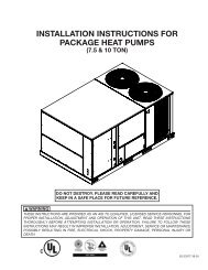
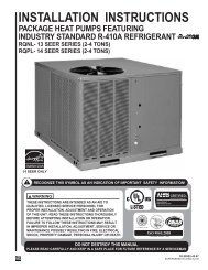
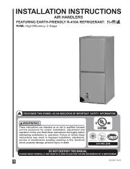
1.0 SAFETY INFORMATION! WARNINGDuct leaks can create an unbalanced system and draw pollutants such asdirt, dust, fumes and odors into the home causing property damage.Fumes and odors from toxic, volatile or flammable chemicals, as well asautomobile exhaust and carbon monoxide (CO), can be drawn into the livingspace through leaking ducts and unbalanced duct systems causingpersonal injury or death (see Figure 1).• If air-moving equipment or ductwork is located in garages or off-garagestorage areas - all joints, seams, and openings in the equipment andduct must be sealed to limit the migration of toxic fumes and odorsincluding carbon monoxide from migrating into the living space.• If air-moving equipment or ductwork is located in spaces containing fuelburning appliances such as water heaters or boilers - all joints, seams,and openings in the equipment and duct must also be sealed to preventdepressurization of the space and possible migration of combustionbyproducts including carbon monoxide into the living space.! WARNING (SEE WARNINGS IN REGARD TO DUCTWORK)Do not install this unit in manufactured (mobile) homes. Improper installationis more likely in manufactured housing due to ductwork material, size, location,and arrangement. Installations in manufactured housing can cause a fireresulting in property damage, personal injury or death.EXCEPTION: Manufactured housing installations are approved only with documentationby a recognized inspection authority that the installation has beenmade in compliance with the instructions and all warnings have beenobserved.! WARNING (SEE SECTION 3.2: VERTICAL UPFLOW & HORIZONTAL LEFT)If unit is to be installed without an indoor coil, return air duct, or plenum, it mustnot be installed directly over combustible material. If installed without an indoorcoil with a return duct or plenum, the air plenum or duct must have a solid sheetmetal bottom with no return air openings, registers or flexible air ducts locateddirectly under the unit. Exposing combustible material to the return opening ofan upflow unit without an indoor coil can cause a fire resulting in property damage,personal injury or death.! WARNING (SEE SECTION 13.7: ECM CONTROL MODULE REPLACEMENT)Always have 240 volt power turned off to the furnace before attempting anyreplacement of the motor or control module. Failure to do so may result in seriousequipment damage, personal injury or death.! WARNING (SEE SECTION 4.0: ELECTRICAL WIRING)Disconnect all power to unit before installing or servicing. More than onedisconnect switch may be required to de-energize the equipment.Hazardous voltage can cause severe personal injury or death.! WARNING (SEE SECTION 4.3: GROUNDING)The unit must be permanently grounded. Failure to do so can result in electricalshock causing personal injury or death.! WARNING (SEE SECTION 13.0: MAINTENANCE)Units with circuit breaker(s) meet requirements as a service disconnectswitch, however, if access is required to the line side (covered) of the circuitbreaker, this side of the breaker(s) will be energized with the breaker(s) deenergized.Contact with the line side can cause electrical shock resulting inpersonal injury or death.Continued on next page ➜3
! WARNING (SEE SECTION 13.5: BLOWER ASSEMBLY REMOVAL & REPLACEMENT)If removal of the blower assembly is required, all disconnect switches supplyingpower to the airhandler must be de-energized and locked (if not in sight of unit)so the field power wires can be safely removed from the blower assembly. Failureto do so can cause electrical shock resulting in personal injury or death.! WARNINGPROPOSITION 65: This appliance contains fiberglass insulation. Respirableparticles of fiberglass are known to the State of California to cause cancer.All manufacturer products meet current Federal OSHA Guidelines for safety.California Proposition 65 warnings are required for certain products, which arenot covered by the OSHA standards.California's Proposition 65 requires warnings for products sold in Californiathat contain or produce any of over 600 listed chemicals known to the State ofCalifornia to cause cancer or birth defects such as fiberglass insulation, lead inbrass, and combustion products from natural gas.All “new equipment” shipped for sale in California will have labels stating thatthe product contains and/or produces Proposition 65 chemicals. Although wehave not changed our processes, having the same label on all our productsfacilitates manufacturing and shipping. We cannot always know “when, or if”products will be sold in the California market.You may receive inquiries from customers about chemicals found in, or producedby, some of our heating and air-conditioning equipment, or found in naturalgas used with some of our products. Listed below are those chemicals andsubstances commonly associated with similar equipment in our industry andother manufacturers.• Glass Wool (Fiberglass) Insulation• Carbon Monoxide (CO).• Formaldehyde• BenzeneMore details are available at the websites for OSHA (Occupational Safety andHealth Administration), at www.osha.gov and the State of California’s OEHHA(Office of Environmental Health Hazard Assessment), at www.oehha.org.Consumer education is important since the chemicals and substances on thelist are found in our daily lives. Most consumers are aware that products presentsafety and health risks, when improperly used, handled and maintained.! WARNING (SEE SECTION 6.0: DUCTWORK)Do not, under any circumstances, connect return ductwork to any other heat producingdevice such as fireplace insert, stove, etc. Unauthorized use of suchdevices may result in fire, carbon monoxide poisoning, explosion, personal injuryor property damage.! WARNINGBecause of possible damage to equipment or personal injury, installation, service,and maintenance should be performed by trained, qualified service personnel.Consumer service is recommended only for filter cleaning/replacement.Never operate the unit with the access panels removed.! WARNING (SEE SECTION 3.3: VERTICAL DOWNFLOW & HORIZONTAL RIGHT)The RXHB-17, RXHB-21, or RXHB-24 combustible floor base is required whencertain units are applied downflow on combustible flooring. Failure to use thebase can cause a fire resulting in property damage, personal injury or death.See clearances for units requiring a combustible floor base. See the accessorysection in this manual for combustible floor base RXHB-.! CAUTION (SEE SECTION 13.7: ECM CONTROL MODULE REPLACEMENT)<strong>Rev</strong>ersing the 5-pin connector on the ECM motor causes immediate failure ofthe control module.Continued on next page ➜4
CAUTION (SEE SECTION 3.2: VERTICAL UPFLOW & HORIZONTAL LEFT)Horizontal units must be configured for right hand air supply. Horizontal drainpan must be located under indoor coil. Failure to use the drain pan can result inproperty damage.CAUTION (SEE SECTION 13.2: INDOOR COIL - DRAIN PAN - DRAIN LINE)In compliance with recognized codes, it is recommended that an auxiliarydrain pan be installed under all evaporator coils or units containing evaporatorcoils that are located in any area of a structure where damage to the buildingor building contents may occur as a result of an overflow of the coil drain panor a stoppage in the primary condensate drain piping. See accessory sectionin this manual for secondary horizontal drain pan RXBM-.CAUTIONWhen used on cooling applications, excessive sweating may occur when unitis installed in an unconditioned space. This can result in property damage.! NOTICEImproper installation, or installation not made in accordance with theUnderwriters Laboratory (UL) certification or these instructions, can resultin unsatisfactory operation and/or dangerous conditions and are not coveredby the unit warranty.! NOTICEIn compliance with recognized codes, it is recommended that an auxiliarydrain pan be installed under all evaporator coils or units containing evaporatorcoils that are located in any area of a structure where damage to thebuilding or building contents may occur as a result of an overflow of thecoil drain pan or a stoppage in the primary condensate drain piping. Seeaccessories section of these instructions for auxiliary horizontal overflowpan information (model RXBM).! NOTICEUse of this air-handler during construction is not recommended. If operationduring construction is absolutely required, the following temporaryinstallation requirements must be followed:Installation must comply with all Installation Instructions in this manualincluding the following items:• Properly sized power supply and circuit breaker/fuse• <strong>Air</strong>-handler operating under thermostatic control;• Return air duct sealed to the air-handler;• <strong>Air</strong> filters must be in place;• Correct air-flow setting for application• Removing the coil and storing it in a clean safe place is highly recommendeduntil construction is completed and the outdoor unit is installed.• Clean air-handler, duct work, and components including coil upon completionof the construction process and verify proper air-handler operatingconditions according as stated in this instruction manual.• NOTE: Electric strip heater elements tend to emit a burning odor for a fewdays if dust has accumulated during construction. Heater elements areeasily damaged. Take great care when cleaning them. Low pressure compressedair is recommended for cleaning elements.2.0 GENERAL INFORMATION2.1 IMPORTANT INFORMATION ABOUT EFFICIENCY AND INDOOR2.1 AIR QUALITYCentral cooling and heating equipment is only as efficient as the duct system that carriesthe cooled or heated air. To maintain efficiency, comfort and good indoor air quality, it isimportant to have the proper balance between the air being supplied to each room andthe air returning to the cooling and heating equipment.Proper balance and sealing of the duct system improves the efficiency of the heatingand air conditioning system and improves the indoor air quality of the home by reducingthe amount of airborne pollutants that enter homes from spaces where the ductwork and/ or equipment is located. The manufacturer and the U.S. Environmental ProtectionAgency’s Energy Star Program recommend that central duct systems be checked by aqualified contractor for proper balance and sealing.5
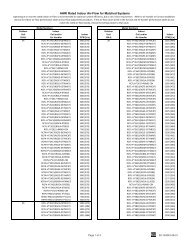
FIGURE 1MIGRATION OF DANGEROUS SUBSTANCES, FUMES, AND ODORS INTO LIVING SPACES2.2 MODEL NUMBER EXPLANATION (SEE FIGURE 2)FIGURE 2MODEL NUMBER EXPLANATION(-) <strong>HKL</strong>–HM 24 17 JATRADEBRANDCLASSIFICATION = AIR HANDLERK = PREMIUM MODELREFRIGERANT = L = R-<strong>410A</strong>HM = A/C OR HEAT PUMPMULTI-POSITION (Upflow &Horizontal Left Is The FactoryConfiguration)DESIGN VARIATIONA = 1ST DESIGNVOLTAGEJ = 208/240/1/60CABINET SIZE17 = 17.5" (600-1200 CFM)21 = 21" (1400-1600 CFM)24 = 24.5" (1600-1800 CFM)CAPACITY24 = 18000/24000 BTUH 48 = 42000/48000 BTUH36 = 30000/36000 BTUH 60 = 60000 BTUH38 = 30000/36000/42000 BTUHNOTES:1) J Voltage (230V) single phase air handler is designed to be used with single or three phase 230 volt power. In the caseof connecting 3-phase power to the air handler terminal block, bring only two leads to the terminal block. Cap, insulateand fully secure the third lead.2) The air handlers are shipped from the factory with the proper indoor coil installed, and cannot be ordered without a coil.3) Electric heat elements are field-installed items.4) The air handlers do not have an internal filter rack. An external filter rack or other means of filtration is required.AVAILABLE MODELS(-)<strong>HKL</strong>-HM2417JA(-)<strong>HKL</strong>-HM3617JA(-)<strong>HKL</strong>-HM3821JA(-)<strong>HKL</strong>-HM4821JA(-)<strong>HKL</strong>-HM4824JA(-)<strong>HKL</strong>-HM6024JA6
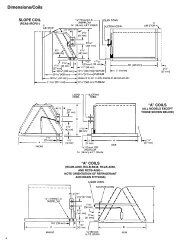
2.3 DIMENSIONS & WEIGHTS (SEE FIGURE 3)FIGURE 3DIMENSIONS AND WEIGHTS -- SINGLE COIL UNITSELECTRICAL CONNECTIONSMAY EXIT TOP OR EITHER SIDEHIGH VOLTAGE CONNECTION 7/8".1 3/32", 1 <strong>31</strong>/32" DIA. KNOCK OUTS.SUPPLY AIR10 5 /16NOTE: 24" CLEARANCE REQUIREDIN FRONT OF UNIT FOR FILTERAND COIL MAINTENANCE.WLOW VOLTAGE CONNECTION5/8" AND 7/8" KNOCK OUT(OUTSIDE OF CABINET)AHAUXILIARY DRAIN CONNECTION3/4" FEMALE PIPE THREAD (NPT)HORIZONTAL APPLICATION ONLYPRIMARY DRAIN CONNECTION3/4" FEMALE PIPE THREAD (NPT)AUXILIARY DRAIN CONNECTION3/4" FEMALE PIPE THREAD (NPT)UPFLOW/DOWNFLOW APPLICATIONONLY19 1 /2RETURN AIR OPENING21 11 /16LIQUID LINE CONNECTIONCOPPER (SWEAT)A-1038-01VAPOR LINE CONNECTIONCOPPER (SWEAT)UPFLOW UNIT SHOWN;UNIT MAY BE INSTALLED UPFLOW, DOWNFLOW.HORIZONTAL RIGHT, OR LEFT AIR SUPPLY.DIMENSIONAL DATAMODELSIZE(-)<strong>HKL</strong>UNITWIDTH“W” IN[mm]UNITHEIGHT“H” IN[mm]RETURN AIR OPENING DIMENSIONSModelCabinet SizeReturn <strong>Air</strong> OpeningWidth (Inches)Return <strong>Air</strong> OpeningDepth/Length (Inches)17 15 7 ⁄8 19 3 ⁄421 19 3 ⁄8 19 3 ⁄424 22 7 ⁄8 19 3 ⁄4SUPPLYAIR FLOWDUCTCOIL (NOM) [L/s]“A” IN.[mm] LO HIUNIT WEIGHT / SHIPPINGWEIGHT (LBS.) [kg]UNIT WITHCOIL (MAX. kW.)2417 17 1 /2" [445] 42 1 /2" [1080] 16" [409] 600 [283] 800 [378] 82/96 [37/44]3617 17 1 /2" [445] 42 1 /2" [1080] 16" [409] 1000 [472] 1200 [566] <strong>92</strong>/106 [37/48]4821 21" [533] 50 1 /2" [1283] 19 1 /2" [495] 1400 [661] 1600 [755] 150/166 [68/75]4824 24 1 /2" [622] 55 1 /2" [1410] 23" [585] 1600 [755] — 162/180 [73/81]6024 24 1 /2" [622] 55 1 /2" [1410] 23" [585] — 1800 [850] 181/198 [82/90]3821 21" [533] 50 1 /2" [1283] 19 1 /2" [495] 1000 [472] 1200 [566] 150/166 [68/75]7
! WARNINGDuct leaks can create an unbalanced system and draw pollutants such asdirt, dust, fumes and odors into the home causing property damage.Fumes and odors from toxic, volatile or flammable chemicals, as well asautomobile exhaust and carbon monoxide (CO), can be drawn into the livingspace through leaking ducts and unbalanced duct systems causingpersonal injury or death (see Figure 1).• If air-moving equipment or ductwork is located in garages or off-garagestorage areas - all joints, seams, and openings in the equipment andduct must be sealed to limit the migration of toxic fumes and odorsincluding carbon monoxide from migrating into the living space.• If air-moving equipment or ductwork is located in spaces containing fuelburning appliances such as water heaters or boilers - all joints, seams,and openings in the equipment and duct must also be sealed to preventdepressurization of the space and possible migration of combustionbyproducts including carbon monoxide into the living space.! NOTICEImproper installation, or installation not made in accordance with theUnderwriters Laboratory (UL) certification or these instructions, can resultin unsatisfactory operation and/or dangerous conditions and are not coveredby the unit warranty.! NOTICEIn compliance with recognized codes, it is recommended that an auxiliarydrain pan be installed under all evaporator coils or units containing evaporatorcoils that are located in any area of a structure where damage to thebuilding or building contents may occur as a result of an overflow of thecoil drain pan or a stoppage in the primary condensate drain piping. Seeaccessories section of these instructions for auxiliary horizontal overflowpan information (model RXBM).2.4 RECEIVINGImmediately upon receipt, all cartons and contents should be inspected for transit damage.Units with damaged cartons should be opened immediately. If damage is found, itshould be noted on the delivery papers, and a damage claim filed with the last carrier.• After unit has been delivered to job site, remove carton taking care not to damageunit.• Check the unit rating plate for unit size, electric heat, coil, voltage, phase, etc. to besure equipment matches what is required for the job specification.• Read the entire instructions before starting the installation.• Some building codes require extra cabinet insulation and gasketing when unit isinstalled in attic applications.• If installed in an unconditioned space, apply caulking around the power wires, controlwires, refrigerant tubing and condensate line where they enter the cabinet. Seal thepower wires on the inside where they exit conduit opening. Caulking is required topre-vent air leakage into and condensate from forming inside the unit, control box,and on electrical controls.• Install the unit in such a way as to allow necessary access to the coil/filter rack andblower/control compartment.• Install the unit in a level position to ensure proper condensate drainage. Make sureunit is level in both directions within 1/8”.• Install the unit in accordance with any local code which may apply and the nationalcodes. Latest editions are available from: “National Fire Protection Association, Inc.,Batterymarch Park, Quincy, MA 02269.” These publications are:• ANSI/NFPA No. 70-(Latest Edition) National Electrical Code.• NFPA90A Installation of <strong>Air</strong> Conditioning and Ventilating Systems.• NFPA90B Installation of warm air heating and air conditioning systems.• The equipment has been evaluated in accordance with the Code of FederalRegulations, Chapter XX, Part 3280.8
2.5 CLEARANCES• All units are designed for “0” inches clearance to combustible material on all cabinetsurfaces.Model Cabinet Size 17 21 24Model Designation kW 15 20 25• Some units require supply duct clearances and combustible floor bases depending onthe heating kW. The following table should be used to determine these requirements:Units with electric heating kW above that listed in the table require a one inch clearanceto combustible material for the first three feet of supply plenum and ductwork.Additionally, if these units are installed downflow, a combustible floor base isrequired. See Accessories for Combustible Floor Base RXHB-XX.Units with electric heating kW equal to or less than the values listed in the table donot require supply ductwork clearances or combustible floor bases.• Vertical units require clearance on at least one side of the unit for electrical connections.Horizontal units require clearance on either top or bottom for electrical connections.Refrigerant and condensate drain connections are made on the front of the unit.(See Figure 4.)• All units require 24 inches maximum access to the front of the unit for service.• These units may be installed in either ventilated or nonventilated spaces.FIGURE 4DIMENSIONS FOR FRONT CONNECT COIL5 15 /164 1 /83 1 /161 3 /161 1 /81 1 /161 3 /82 13 /165 1 /45 3 /83.0 APPLICATIONS3.1 ZONING SYSTEMSThe manufacturer does not currently provide or support zoning. However, zoning systemscan be installed with a variable speed air-handler as long as the zoning equipment manufacturersspecifications and installation instructions are met and followed.The preferred zoning method is to use a “bypass” system which is properly installed formaximum efficiency. In these systems, excess air is routed back through the system tobe used again – this is opposed to a “dump” system in which excess air is routed to azone where it is expected that the extra heat or cooling would be least noticed.If installed as a “bypass” system, the installation must have an optional freeze statinstalled to prevent the coil from icing with excess bypass cooling. Also, if the zoningequipment manufacturer provides a limit switch (usually provided by the zoning manufacturer),this limit must be installed in the system to prevent the furnace from overheating.9
3.2 VERTICAL UPFLOW AND HORIZONTAL LEFTThe air handler unit is factory shipped for vertical upflow and horizontal left application.• If return air is to be ducted, install duct flush with floor. Use fireproof resilient gasket 1/8to 1/4 in. thick between duct, unit and floor. Set unit on floor over opening.• Support along the length of the unit, on all units installed horizontally. Do not supportor suspend unit from both ends without support in the center of the cabinet. If unit isto be supported or suspended from corners, run two reinforcing rails length of unitand support or suspend from reinforcing rails.• Secondary drain pan kits RXBM- are required when the unit is configured for the horizontalleft position over a finished ceiling and/or living space. (See Section 15.0:Accessories - Kits - Parts.)FIGURE 5VERTICAL DOWNFLOW & HORIZONTAL RIGHT APPLICATIONSRAILSDETAIL AENSURE THE RETAIN-ING CHANNEL IS FULLYENGAGED WITH THECOIL RAIL.RAILSCAUTIONHorizontal units must be configured for right hand air supply. Horizontal drainpan must be located under indoor coil. Failure to use the drain pan can resultin property damage.3.3 VERTICAL DOWNFLOW AND HORIZONTAL RIGHTConversion to Vertical Downflow/Horizontal Right: A vertical upflow unit may be convertedto vertical downflow/horizontal right. (See Figure 5.) Remove the door and indoorcoil and reinstall 180° from original position.IMPORTANT: To comply with certification agencies and the National Electric Code forhorizontal right application, the circuit breaker(s) on field-installed electric heater kitsmust be re-installed per procedure below so that the breaker switch “on” position andmarking is up and, “off” position and marking is down.- To turn breaker(s): Rotate one breaker pair (circuit) at a time starting with the one on theright. Loosen both lugs on the load side of the breaker. Wires are bundles with wire ties,one bundle going to the right lug and one bundle going to the left lug.- Using a screwdriver or pencil, lift white plastic tab with hole away from breaker untilbreaker releases from mounting opening (see Figure 6).- With breaker held in hand, rotate breaker so that “on” position is up, “off” position is downwith unit in planned vertical mounting position. Insert right wire bundle into top rightbreaker lug, ensuring all strands of all wires are inserted fully into lug, and no wire insulationis in lug.10
FIGURE 6ROTATING CIRCUIT BREAKER- Tighten lug as tight as possible while holding circuit breaker. Check wires and make sureeach wire is secure and none are loose. Repeat for left wire bundle in left top circuitbreaker lug.- Replace breaker by inserting breaker mounting tab opposite white pull tab in opening,hook mounting tab over edge in opening.- With screwdriver or pencil, pull white tab with hole away from breaker while setting thatside of breaker into opening. When breaker is in place, release tab, locking circuit breakerinto location in opening.- Repeat above operation for remaining breaker(s) (if more than one is provided).- Replace single point wiring jumper bar, if it is used, on line side of breaker and tightensecurely.- Double check wires and lugs to make sure all are secure and tight. Check to make sureunit wiring to circuit breaker load lugs match that shown on the unit wiring diagram.! WARNINGThe RXHB-17, RXHB-21, or RXHB-24 combustible floor base is required whencertain units are applied downflow on combustible flooring. Failure to use thebase can cause a fire resulting in property damage, personal injury or death.See clearances for units requiring a combustible floor base. See the accessorysection in this manual for combustible floor base RXHB-.• Rotate unit into the downflow position, with the coil compartment on top and the blower compartmenton bottom.• Reinstall the indoor coil 180° from original position. Ensure the retaining channel is fullyengaged with the coil rail. (See Figure 5, Detail A.)• Secondary drain pan kits RXBM- are required when the unit is configured for the horizontalright position over a finished ceiling and/or living space. (See Section 15.0:Accessories - Kits - Parts.)IMPORTANT: Units cannot be installed horizontally laying on or suspended from theback of the unit.11
FIGURE 7INDOOR COIL AND DRAIN PAN SET-UPSTRAPSREAR WATER CATCHERHORIZONTAL ADAPTERKITFRONT WATERCATCHERTOP AIR STOPVAPOR LINECONNECTIONAUXILIARYHORIZONTALDRAINCONNECTIONPRIMARYDRAINCONNECTIONAUXILIARYUPFLOW/DOWNFLOWDRAIN CONNECTIONLIQUID LINECONNECTIONVERTICALDRAIN PANA-1037-013.4 INSTALLATION IN AN UNCONDITIONED SPACEIMPORTANT: There are two pairs of coil rails in the air handler for default and counterflow application. If the air handler is installed in an unconditioned space, the two unusedcoil rails should be removed to minimize air handler surface sweating. (See Figure 5.)The coil rails can be easily removed by taking off the 6 mounting screws from both sidesof the cabinet.4.0 ELECTRICAL WIRINGField wiring must comply with the National Electric Code (C.E.C. in Canada) and anyapplicable local ordinance.! WARNINGDisconnect all power to unit before installing or servicing. More than one disconnectswitch may be required to de-energize the equipment. Hazardous voltagecan cause severe personal injury or death.4.1 POWER WIRINGIt is important that proper electrical power is available for connection to the unit modelbeing installed. See the unit nameplate, wiring diagram and electrical data in the installationinstructions.• If required, install a branch circuit disconnect of adequate size, located within sight of,and readily accessible to the unit.• IMPORTANT: After the Electric Heater is installed, units may be equipped with one,two, or three 60 amp. circuit breakers. These breaker(s) protect the internal wiring inthe event of a short circuit and serve as a disconnect. Circuit breakers installed withinthe unit do not provide over-current protection of the supply wiring and therefore maybe sized larger than the branch circuit protection.• Supply circuit power wiring must be 75°C minimum copper conductors only. SeeElectrical Data in this section for ampacity, wire size and circuit protector requirement.Supply circuit protective devices may be either fuses or “HACR” type circuit breakers.12
• Power wiring may be connected to either the right, left side or top. Three 7 /8”, 1 3 /32”,1 <strong>31</strong> /32” dia. concentric knockouts are provided for connection of power wiring to unit.• Power wiring is connected to the power terminal block(s) in unit control compartment.4.2 CONTROL WIRINGIMPORTANT: Class 2 low voltage control wire should not be run in conduit with powerwiring and must be separated from power wiring, unless Class 1 wire of proper voltagerating is used.• Low voltage control wiring should be 18 AWG color-coded (105°C minimum). Forlengths longer than 100 ft., 16 AWG wire should be used.• Low voltage control connections are made by extending wires from top of air handlerusing wire nuts.• See wiring diagrams attached to indoor and outdoor sections to be connected• Do not leave excess field control wiring inside unit, pull excess control wire to outsideof unit and provide strain relief for field control wiring on inside of cabinet at pointwiring penetrates cabinet.• Make sure, after installation, separation of control wiring and power wiring has beenmaintained.FIELD WIRE SIZE FOR 24 VOLT THERMOSTAT CIRCUITSThermostat Load - Amps3.02.52.0SOLID COPPER WIRE - AWG.16161850141416100121214150101212200Length of Run - Feet (1)101012250(1) Wire length equals twice the run distance.NOTE: Do not use control wiring smaller than No. 18 AWG between thermostat and outdoor unit.1010103004.3 GROUNDING! WARNINGThe unit must be permanently grounded. Failure to do so can result in electricalshock causing personal injury or death.• Grounding may be accomplished by grounding metal conduit when installed in accordancewith electrical codes to the unit cabinet.• Grounding may also be accomplished by attaching ground wire(s) to ground lug(s)provided in the unit wiring compartment.• Ground lug(s) are located close to wire entrance on left side of unit (upflow). Lug(s)may be moved to marked locations near wire entrance on right side of unit (upflow), ifalternate location is more convenient.• Use of multiple supply circuits require grounding of each circuit to lug(s) provided inunit.13
4.4 BLOWER MOTOR ELECTRICAL DATAMODELSIZE(-)<strong>HKL</strong>VOLTAGEPHASEHERTZHPRPMSPEEDSCIRCUITAMPSMINIMUMCIRCUITAMPACITYMAXIMUMCIRCUITPROTECTOR2417 208/240 1 60 1/3 300-1100 2 2.2 3 153617 208/240 1 60 1/2 300-1100 2 3.1 4.0 153821/4821 208/240 1 60 3/4 300-1100 2 4.0 5.0 156024 208/240 1 60 3/4 300-1100 2 4.4 6 1514
4.5 ELECTRIC HEAT ELECTRICAL DATAInstallation of the UL Listed original equipment manufacturer provided heater kits listed in the following table is recommendedfor all auxiliary heating requirements.AIR-HANDLERMODELHEATERMODELNO.HIGH KW ELECTRIC HEAT ELECTRICAL DATA: (-)<strong>HKL</strong>HEATERKW208/240V PH/HZ NO.ELEMENTS- KW PERTYPE SUPPLYCIRCUITSINGLE CIRCUITMULTIPLE CIRCUITCIRCUITAMPS.MOTORAMPACITYMINIMUMCIRCUITAMPACITYMAXIMUMCIRCUITPROTECTIONRXBH-1724A03J 2.25/3.0 1/60 1-3.0 SINGLE 10.8/12.5 2.2 17/19 20/20RXBH-1724A05J 3.6/4.8 1/60 1-4.8 SINGLE 17.3/20.0 2.2 25/28 25/30RXBH-1724A<strong>07</strong>J 5.4/7.2 1/60 2-3.6 SINGLE 26.0/30.0 2.2 36/41 40/45RXBH-1724A10J 7.2/9.6 1/60 2-4.8 SINGLE 34.6/40.0 2.2 46/53 50/60(-)<strong>HKL</strong> 9.4/12.5 1/60 3-4.17 SINGLE 45.1/52.1 2.2 60/68 60/70-2417 RXBH-1724A13J 3.1/4.2 1/60 1-4.17 MULTIPLE CKT 1 15.0/17.4 2.2 22/25 25/256.3/8.3 1/60 2-4.17 MULTIPLE CKT 2 30.1/34.7 0 38/44 40/45RXBH-1724A<strong>07</strong>C 5.4/7.2 3/60 3-2.4 SINGLE 15.0/17.3 2.2 22/25 25/25RXBH-1724A10C 7.2/9.6 3/60 3-3.2 SINGLE 20.0/23.1 2.2 28/32 30/35RXBH-1724A13C 9.4/12.5 3/60 3-4.17 SINGLE 26.1/30.1 2.2 36/41 40/45RXBH-1724A03J 2.25/3.0 1/60 1-3.0 SINGLE 10.8/12.5 3.1 18/20 20/20RXBH-1724A05J 3.6/4.8 1/60 1-4.8 SINGLE 17.3/20.0 3.1 26/29 30/30RXBH-1724A<strong>07</strong>J 5.4/7.2 1/60 2-3.6 SINGLE 26.0/30.0 3.1 37/42 40/45RXBH-1724A10J 7.2/9.6 1/60 2-4.8 SINGLE 34.6/40.0 3.1 48/54 50/609.4/12.5 1/60 3-4.17 SINGLE 45.1/52.1 3.1 61/69 70/70RXBH-1724A13J 3.1/4.2 1/60 1-4.17 MULTIPLE CKT 1 15.0/17.4 3.1 23/26 25/30(-)<strong>HKL</strong> 6.3/8.3 1/60 2-4.17 MULTIPLE CKT 2 30.1/34.7 0 38/44 40/45-3617 10.8/14.4 1/60 3-4.8 SINGLE 51.9/60.0 3.1 69/79 70/80RXBH-1724A15J 3.6/4.8 1/60 1-4.8 MULTIPLE CKT 1 17.3/20.0 3.1 26/29 30/3<strong>07</strong>.2/9.6 1/60 2-4.8 MULTIPLE CKT 2 34.6/40.0 0 44/50 45/5012.8/17.0 1/60 3-5.68 SINGLE 61.6/70.8 3.1 81/93 90/100RXBH-1724A18J 4.3/5.7 1/60 1-5.68 MULTIPLE CKT 1 20.5/23.6 3.1 30/34 30/358.5/11.3 1/60 2-5.68 MULTIPLE CKT 2 41.1/47.2 0 52/59 60/60RXBH-1724A<strong>07</strong>C 5.4/7.2 3/60 3-2.4 SINGLE 15.0/17.3 3.1 23/26 25/30RXBH-1724A10C 7.2/9.6 3/60 3-3.2 SINGLE 20.0/23.1 3.1 29/33 30/35RXBH-1724A13C 9.4/12.5 3/60 3-4.17 SINGLE 26.1/30.1 3.1 37/42 40/45RXBH-1724A15C 10.8/14.4 3/60 3-4.8 SINGLE 30.0/34.6 3.1 42/48 45/50RXBH-1724A18C 12.8/17.0 3/60 3-5.68 SINGLE 35.5/41.0 3.1 49/56 50/60RXBH-1724A05J 3.6/4.8 1/60 1-4.8 SINGLE 17.3/20.0 4.0 27/30 30/30RXBH-1724A<strong>07</strong>J 5.4/7.2 1/60 2-3.6 SINGLE 26.0/30.0 4.0 38/43 40/45RXBH-1724A10J 7.2/9.6 1/60 2-4.8 SINGLE 34.6/40.0 4.0 49/55 50/6010.8/14.4 1/60 3-4.8 SINGLE 51.9/60.0 4.0 70/80 70/80RXBH-1724A15J 3.6/4.8 1/60 1-4.8 MULTIPLE CKT 1 17.3/20.0 4.0 27/30 30/3<strong>07</strong>.2/9.6 1/60 2-4.8 MULTIPLE CKT 2 34.6/40.0 0.0 44/50 45/5012.8/17.0 1/60 4-4.26 SINGLE 61.6/70.8 4.0 82/94 90/100RXBH-1724A18J 6.4/8.5 1/60 2-4.26 MULTIPLE CKT 1 30.8/35.4 4.0 44/50 45/506.4/8.5 1/60 2-4.26 MULTIPLE CKT 2 30.8/35.4 0.0 39/45 40/45(-)<strong>HKL</strong>14.4/19.2 1/60 4-48 SINGLE 69.2/80 4.0 <strong>92</strong>/105 100/110RXBH-24A20J-3821(3 1 7.2/9.6 1/60 2-4.8 MULTIPLE CKT 1 34.6/40.0 4.0 49/55 50/60⁄2, 4-ton only)-4821 7.2/9.6 1/60 2-4.8 MULTIPLE CKT 2 34.6/40.0 0.0 44/50 45/5018.0/24.0 1/60 6-4.0 SINGLE 86.4/99.9 4.0 113/130 125/150RXBH-24A25J 6.0/8.0 1/60 2-4.0 MULTIPLE CKT 1 28.8/33.3 4.0 42/47 45/50(4-ton only) 6.0/8.0 1/60 2-4.0 MULTIPLE CKT 2 28.8/33.3 0.0 36/42 40/456.0/8.0 1/60 2-4.0 MULTIPLE CKT 3 28.8/33.3 0.0 36/42 40/45RXBH-1724A<strong>07</strong>C 5.4/7.2 3/60 3-2.4 SINGLE 15.0/17.3 4.0 24/27 25/30RXBH-1724A10C 7.2/9.6 3/60 3-3.2 SINGLE 20.0/23.1 4.0 30/34 30/35RXBH-1724A15C 10.8/14.4 3/60 3-4.8 SINGLE 30.0/34.6 4.0 43/49 45/50RXBH-1724A18C 12.8/17.0 3/60 3-2.84 SINGLE 35.6/41.0 4.0 50/57 50/60RXBH-24A20C*(3 1 ⁄2, 4-ton only)14.4/19.2 3/60 3-3.2 SINGLE 40.0/46.2 4.0 55/63 60/7<strong>07</strong>.2/9.6 3/60 3-3.2 MULTIPLE CKT 1 20.0/23.1 4.0 30/34 30/357.2/9.6 3/60 3-3.2 MULTIPLE CKT 2 20.0/23.1 0.0 25/29 25/3018.0/24.0 3/60 6-4.0 SINGLE 50.0/57.8 4.0 68/78 70/80RXBH-24A25C*9.0/12.0 3/60 3-4.0 MULTIPLE CKT 1 25.0/28.9 4.0 37/42 40/45(4-ton only)9.0/12.0 3/60 3-4.0 MULTIPLE CKT 2 25.0/28.9 0.0 32/37 35/4015
4.5 Electric Heat Electrical Data: (-)<strong>HKL</strong> - continuedAIR-HANDLERMODELHEATERMODELNO.HEATERKW208/240V PH/HZ NO.ELEMENTS- KW PERTYPE SUPPLYCIRCUITSINGLE CIRCUITMULTIPLE CIRCUITCIRCUITAMPS.MOTORAMPACITYMINIMUMCIRCUITAMPACITYMAXIMUMCIRCUITPROTECTIONRXBH-1724A05J 3.6/4.8 1/60 1-4.8 SINGLE 17.3/20.0 4.4 30/35 28/<strong>31</strong>RXBH-1724A<strong>07</strong>J 5.4/7.2 1/60 2-3.6 SINGLE 26.0/30.0 4.4 38/43 40/45RXBH-1724A10J 7.2/9.6 1/60 2-4.8 SINGLE 34.6/40.0 4.4 49/56 50/60RXBH-1724A15J 10.8/14.4 1/60 3-4.8 SINGLE 51.9/60.0 4.4 71/81 80/90RXBH-1724A15J3.6/4.8 1/60 1-4.8 MULTIPLE CKT1 17.3/20.0 4.4 28/<strong>31</strong> 30/357.2/9.6 1/60 2-4.8 MULTIPLE CKT 2 34.6/40.0 0 44/50 45/50RXBH-1724A18J 12.8/17 1/60 4-4.26 SINGLE 61.6/70.8 4.4 83/94 90/100RXBH-1724A18J6.4/8.5 1/60 2-4.26 MULTIPLE CKT 1 30.8/35.4 4.4 44/50 45/506.4/8.5 1/60 2-4.26 MULTIPLE CKT 2 30.8/35.4 0 39/45 40/45RXBH-24A20J 14.4/19.2 1/60 4-4.8 SINGLE 69.2/80 4.4 93/106 100/110RXBH-24A20J7.2/9.6 1/60 2-4.8 MULTIPLE CKT 1 34.6/40.0 4.4 49/56 50/6<strong>07</strong>.2/9.6 1/60 2-4.8 MULTIPLE CKT 2 34.6/40.0 0 44/50 45/50RXBH-24A25J 18.0/24.0 1/60 6-4.0 SINGLE 86.4/99.9 4.4 114/1<strong>31</strong> 125/1506.0/8.0 1/60 2-4.0 MULTIPLE CKT 1 28.8/33.3 4.4 42/48 45/50(-)<strong>HKL</strong> RXBH-24A25J 6.0/8.0 1/60 2-4.0 MULTIPLE CKT 2 28.8/33.3 0 36/42 40/45-4824 6.0/8.0 1/60 2-4.0 MULTIPLE CKT 3 28.8/33.3 0 36/42 40/45-6024 RXBH-24A30J 21.6/28.8 1/60 6-4.8 SINGLE 103.8/120. 4.4 136/156 150/175(1800 CFM only)RXBH-24A30J 7.2/9.6 1/60 2-4.8 MULTIPLE CKT 1 34.6/40.0 4.4 49/56 50/60(5-ton only) 7.2/9.6 1/60 2-4.8 MULTIPLE CKT 2 34.6/40.0 0 44/50 45/50(1800 CFM only) 7.2/9.6 1/60 2-4.8 MULTIPLE CKT 3 34.6/40.0 0 44/50 45/50RXBH-1724A<strong>07</strong>C 5.4/7.2 3/60 3-2.4 SINGLE 15.0/17.3 4.4 25/28 25/30RXBH-1724A10C 7.2/9.6 3/60 3-3.2 SINGLE 20.0/23.1 4.4 <strong>31</strong>/35 35/35RXBH-1724A15C 10.8/14.4 3/60 3-4.8 SINGLE 30.0/34.6 4.4 43/49 45/50RXBH-1724A18C 12.8/17.0 3/60 3-2.84 SINGLE 35.6/41.0 4.4 50/57 50/6014.4/19.2 3/60 3-3.2 SINGLE 40.0/46.2 4.4 56/64 60/70RXBH-24A20C* 7.2/9.6 3/60 3-3.2 MULTIPLE CKT 1 20.0/23.1 4.4 <strong>31</strong>/35 35/357.2/9.6 3/60 3-3.2 MULTIPLE CKT 2 20.0/23.1 0 25/29 25/30RXBH-24A25C* 18.0/24.0 3/60 6-4.0 SINGLE 50.0/57.8 4.4 68/78 70/80RXBH-24A25C9.0/12.0 3/60 3-4.0 MULTIPLE CKT 1 25.0/28.9 4.4 37/42 40/459.0/12.0 3/60 3-4.0 MULTIPLE CKT 2 25.0/28.9 0 32/37 35/40RXBH-24A30C*(1800 CFM only)21.6/28.8 3/60 6-4.8 SINGLE 60.0/69.4 4.4 81/93 90/100RXBH-24A30C 10.8/14.4 3/60 3-4.8 MULTIPLE CKT 1 30.0/34.7 4.4 43/50 45/50(5-ton only)(1800 CFM only)10.8/14.4 3/60 3-4.8 MULTIPLE CKT 2 30.0/34.7 0 38/44 40/45NOTES:* Values only. No single point kit available.• Electric heater BTUH - (heater watts + motor watts) x 3.414 (see airflow table for motor watts.)• Supply circuit protective devices may be fuses or “HACR” type circuit breakers.• Largest motor load is included in single circuit and multiple circuit 1.• If non-standard fuse size is specified, use next size larger fuse size.• J Voltage (230V) single phase air handler is designed to be used with single or three phase 230 volt electric heaters. In the caseof connecting 3-phase power to the air handler terminal block without the heater, bring only two leads to the terminal block. Cap,insulate and fully secure the third lead.• If the kit is listed under both single and multiple circuits, the kit is shipped from factory as multiple circuits. For single phase application,Jumper bar kit RXBJ-A21 and RXBJ-A<strong>31</strong> can be used to convert multiple circuits to a single supply circuit. Refer toAccessory Section for details.• The airflow for continuous fan is set 50% of the cooling airflow.16
4.5A HEATER KIT SUPPLEMENTAL INFORMATIONIf a heaterkit is listedbothSingleand Multicircuit,thekit isshippedas a Multicircuitandwillrequire asinglepoint kit(-)HLA-HM4821JAMARK HEATER INSTALLED/L’APPAREIL DE CHAUFFAGE DE MARQUE A INSTALLEAIR CONDITIONING DIVISIONOnly listed kits can be appliedContractorshould “markor check” theleft column forthe kit installedThese are therequired maximumand minimumcircuitbreaker sizesfor overcurrentprotection andshould not beconfused withthe size of thebreakersinstalled in theheater kit.Heater Kit Supplemental Information: What allows the manufacturer to use standard Circuit Breakersup to 60 amps inside the air handler, when using an approved Heater Kit?National Electric Code (Section 424-22b) and our UL requirements allow us to subdivide heating elementcircuits, of less than 48 amps, using breakers of not more than 60 amps and, additionally by, NEC 424-3b, arating not less than 125 percent of the load and NEC 424-22c, which describes the supplementary overcurrentprotection required to be factory-installed within, or on the heater. The breakers in the heater kit are not,and have never been, by NEC, intended to protect power wiring leading to the air handler unit. The breakersin the heating kit are for short circuit protection. All internal unit wiring, where the breakers apply, has beenUL approved for short circuit protection.Ampacity, (not breaker size), determines supply circuit wire size. The ampacity listed on the unit rating plateand the Maximum and Minimum circuit breaker size (noted above) or in the units specification sheet orinstallation instructions provides the information to properly select wire and circuit breaker/protector size. TheNational Electric Code (NEC) specifies that the supply or branch circuit must be protected at the source.17
5.0 ECM MOTOR INTERFACE CONTROL BOARDIMPORTANT: Factory switch settings are all “OFF” except switch 9, which is “ON”.5.1 ECM MOTOR INTERFACE CONTROL AND SETTINGSIMPORTANT: Disconnect power to air handler when changing DIP switch positions. Even ifblower is not operating, the motor will not recognize changes in DIP switch positions until unitpower is removed and then restored.The (-)<strong>HKL</strong> series air handlers have ECM blower motors, which deliver a constant level of airflowover a wide range of external static pressures (up to 1.0" W.C.). The interface board providesthe required communications between the thermostat and the ECM blower motor. The(-)<strong>HKL</strong> series of air handlers feature:• An automotive-style ATC blade fuse for transformer protection (3 amp).• An on-board LED to indicate blower CFM.TABLE 1SWITCH FUNCTIONSSwitchFunction1 & 2 Cooling <strong>Air</strong>flow Settings3 & 4 Cooling <strong>Air</strong>flow Adjustment5 & 6 Heating <strong>Air</strong>flow Settings7 & 8 Cooling Delay Profiles9 & 10 On-Demand Dehumidification – Active & PassiveThere is a bank of 10 DIP switches on the interface board that define the operation of theECM motor (see Table 1).Refer to Figure 8 for switch identification and factory default settings.NOTE: All units are shipped from the factory on High <strong>Air</strong>flow.FIGURE 8ECM MOTOR FACTORY SETTINGS18
5.2 USING THE ON-BOARD LED TO DETERMINE BLOWER CFMThe (-)<strong>HKL</strong> interface board LED (see Figure 9) indicates blower output by flashing one (1)second for every 100 CFM of airflow. The LED will pause 1/10 second between each flash.After the blower CFM has been displayed, the LED will illuminate dimly for 10 seconds beforerepeating the sequence. (See Table 2.)NOTE: If airflow is not a multiple of 100 CFM, the last LED flash is a fraction of a second of100 CFM. (<strong>Air</strong>flow must be verified, flash code is what is set.)FIGURE 9IFC BOARDLEDFUSETABLE 2LED FLASH CODESINTERFACEBOARDDIP SWITCHSETTINGS1200 CFM600 CFM950 CFMSOME EXAMPLES OFLED OUTPUT• Flashes 12 times• Illuminate dimly 10 seconds, repeat sequence• Flashes 6 times• Illuminate dimly 10 seconds, repeat sequence• Flashes 9 times, flash once for 1 /2 second• Illuminate dimly 10 seconds, repeat sequence5.3 COOLING AND HEAT PUMP HEATING MODE AIRFLOW SETTINGS(SEE FIGURE 10)The (-)<strong>HKL</strong>-series of air handlers allow a wide range of airflow settings for cooling and heatpump operation. These airflow settings are selected via DIP switches 1 & 2 on the interfaceboard. DIP switches 1 & 2 allow the user to tailor the airflow for the particular installation.DIP switches 5 & 6 control electric heat air-flow levels on (-)<strong>HKL</strong> air-handlers. Electric heatair-flow must be set to match the cooling/heat pump air-flow for proper operation. Therefore,settings for DIP switches 5 & 6 should match DIP switches 1 & 2 respectively.NOTE: Cooling/heating air-flow adjustments using DIP switches 3 & 4 also affect electric heatairflow on (-)<strong>HKL</strong> air-handlers.19
FIGURE 10FACTORY AIRFLOW SETTINGS FOR SWITCHES 1 AND 2, 5 AND 65 6 5 6 5 6 5 6 – HEATING AIRFLOW1 2 1 2 1 2 1 2 – COOLING AIRFLOWONONONONAB C DSELECTION(ONE OFTHE PAIRS)SWITCH 1AND 5POSITIONSWITCH 2AND 6POSITION(-)<strong>HKL</strong> 17/1 1 /2 & 2 TONCOOLING/HEATING AIRFLOWCABINET SIZE/COOLING CAPACITY(-)<strong>HKL</strong> 17/2 1 /2 & 3 TON(-)<strong>HKL</strong> 21/3 1 /2 & 4 TONY1 Y2 Y1 Y2 Y1 Y2(-)<strong>HKL</strong> 24/4 & 5 TONA OFF OFF 800 800 1200 1200 1600 1600 1800 1800B ON OFF 800 800 1200 1200 1600 1600 1800 1800C OFF ON 600 600 1000 1000 1400 1400 1600 1600D ON ON 600 600 1000 1000 1400 1400 1600 1600Y1Y25.4 COOLING/HEATING AIRFLOW ADJUSTMENTS (SEE FIGURE 10)Cooling/heating airflow may be adjusted +10% or –10% from nominal airflow using switches 3& 4.Refer to Figure 11 for switch positions to achieve the desired adjustments in airflow.NOTE: Continuous fan speed is NOT affected by switches 3 & 4 selections. Continuous fanspeed is 50% of the selected cooling speed for switches 1 & 2.IMPORTANT: The use of On Demand Dehumidification overrides the cooling airflow adjustmentswhen high humidity is detected by a dehumidifying thermostat or humidistat when connectedto the ODD wire (See Figure 16). Refer to the Cooling Mode Dehumidification sectionfor more information.5.5 ELECTRIC HEAT AIRFLOW SETTINGS/ADJUSTMENTSDIP switches 5 & 6 control electric heat air-flow levels on (-)<strong>HKL</strong> air-handlers.FIGURE 11COOLING AIRFLOW ADJUSTMENTSON3 4 3 4 3 4 3 4ONONONAB C DCOOLINGSELECTION SWITCH 3 SWITCH 4 AIRFLOWPOSITION POSITION ADJUSTMENTA OFF OFF NONEB ON OFF 10%C OFF ON -10%D ON ON NONE20
FIGURE 12FACTORY AIRFLOW SETTINGS FOR SWITCHES 5 AND 6ON5 6 5 6 5 6 5 6ONONONA B C DELECTRIC HEAT AIR FLOWSELECTION SWITCH 5POSITIONSWITCH 6POSITION(-)<strong>HKL</strong>-HM2417(-)<strong>HKL</strong>-HM3617(-)<strong>HKL</strong>-HM3821(-)<strong>HKL</strong>-HM482(-)<strong>HKL</strong>-HM4824(-)<strong>HKL</strong>-HM6024A OFF OFF 800 1200 1200 1600 1800 1800B ON OFF 600 600 600 800 800 800C OFF ON 800 1000 1000 1400 1600 1600D ON ON 600 600 600 800 800 8005.6 COOLING DELAY PROFILESThe (-)<strong>HKL</strong> air handlers are shipped with a default 30 second blower OFF delay profile formaximum efficiency.IMPORTANT: Blower ON delay profiles are not used in heating mode.5.7 COOLING MODE DEHUMIDIFICATION (PASSIVE: FACTORYPROGRAMMED PROFILES)Factory board settings will provide general overall performance under average conditions.Use these Advanced Profiles to optimize performance and to add soft motor operation.Please be sure that you check for correct airflow and adjust refrigerant charge based on yourMaximum Capacity and <strong>Air</strong>flow using the Factory AIRFLOW SETTINGS. Switches 1 and 2should be set for the tonnage and airflow requirement for the system. Advanced <strong>Air</strong>flow settingswill, in most cases, greatly reduce airflow to the system and change the system’s Latentand Sensible capacity splits. The control board flashes CFM to the nearest 50 CFM calculated.We suggest that trouble-shooting be done with switches in the factory position forverification of refrigerant charge and airflow through the duct system.FIGURE 13COOLING AIRFLOW ADJUSTMENTSAdvanced Cooling AdjustmentsSwitch 7 and 8 Settings and Characteristics FactoryS7 on off on offS8 off on on offMoistureRemoval Highest Good Lowest StandardTABLE 3S7S8On OffS7S8On OffS7S8On OffOperatingSequenceOperatingSequencePre-programmed CFM RatesRamp Times CFM Reduction5 minutes 18% Less5 to 12.5 minutes 12% Lessafter 12.5 minutes 100% FullPre-programmed CFM RatesRamp Times CFM Reduction3 minutes 25% Less3 to 8 minutes 12% Lessafter 8 minutes 100% FullPre-programmed CFM RatesRamp Times CFM ReductionOperating3 minutes 18% LessSequenceafter 3 minutes 100% Full21
TABLE 4SELECTION A EXPLANATION: MAXIMUM LATENT REMOVAL – PASSIVESWITCH POSITIONSCABINET SIZE/COOLING CAPACITYCFMSWITCH 1POSITIONSWITCH 2POSITIONSWITCH 9POSITIONSWITCH 10POSITION17/1 1 ⁄2 & 2.017/2.0 & 3.021/3.021/3 1 ⁄2 & 4.024/4.0 & 5.0OFF OFF OFF OFF 680 1020 1360 1530ON OFF OFF OFF 680 1020 1360 1530OFF ON OFF OFF 510 850 1190 1360ON ON OFF OFF 510 850 1190 1360NOTE: The control is equipped with 3 preprogrammed CFM rates for moisture removal.These are selected with switches S7 and S8. Please refer to Figure 13 and Table 3 for moistureremoval options.• Multiple Switch Setting CAUTION: Switches 7 and 8 provide dehumidification by using preprogrammedairflow profiles and airflow percentage reductions that reduce airflow basedfrom selections using switches 3 and 4. Exception: If Minus 10% is selected from switches3 and 4, the selections of 7 and 8 reduction will be from the nominal CFM selected on 1 and2. Multiple reductions in airflow will occur that may adversely reduce airflow if 7 and 8 profilesare used with a humidistat or dehumidifying thermostat. CAUTION: If a Humidistat, ora Thermostat with a Dehumidifying feature, is to be used, leave switches 7 and 8 in theFACTORY POSITIONS (both in the off position) and skip to AdvancedDehumidification Profiles.5.8 COOLING MODE DEHUMIDIFICATION – ACTIVE(Active Dehumidification: ODD senses RH% and adjusts airflow to maintain selected humiditylevels.)“On Demand Dehumidification”, ODD, terminal input allows the user to have automatic dehumidificationin the cooling mode that is controlled by the user’s dehumidifying thermostat orhumidistat setting. When the humidity exceeds the humidistat setting, the airflow is decreasedby a preprogrammed amount. This results in higher latent capacity and increases the level ofcomfort.Use of the On Demand Dehumidification feature is important with the (-)<strong>HKL</strong> air handlers.These systems typically have a latent capacity between 23% to 25% of total system capacity.On Demand Dehumidification drops cooling airflow to boost latent capacity without sacrificingtotal system capacity.The interface board “ODD” terminal input is designed to be used with a dehumidifying thermostator a traditional humidistat (see Figure 16). For proper operation, the dehumidifying thermostator humidistat must conform to these conditions:IMPORTANT: A humidistat can be used for dehumidification as long as it is the type wherethe contacts close when the humidity is low. Dehumidistat 41-25066-02 can also be usedsince its contacts close when the humidity is low. Other dehumidistats are not compatible withthe interface board. Typical dehumidistats apply a 24V signal when humidity is high and areincompatible with the interface board.Refer to the typical thermostat wiring section (See Figures 14-19) for recommended dehumidifyingthermostats.22
5.8A Typical Thermostat Wiring DiagramsWIRE COLOR CODEBK – BLACK G – GREEN PR – PURPLE Y – YELLOWBR – BROWN GY – GRAY R – REDBL – BLUE O – ORANGE W – WHITEFIGURE 14TYPICAL THERMOSTAT: STRAIGHT COOLING WITH ELECTRICHEATSingle-Stage A/C ThermostatwG Y C RFIGURE 15TYPICAL THERMOSTAT: STRAIGHT COOLING WITH ELECTRICHEAT AND USING A HUMIDISTAT FOR DEHUMIDIFICATIONSingle-Stage A/C ThermostatWG Y C RHumidistat<strong>Air</strong> <strong>Handler</strong><strong>Air</strong> <strong>Handler</strong>W2GYW1BODDCRY2W/BLG/BKYW/BKBLG/YBRRY/BLA/C Outdoor UnitYCW2GYW1BODDCRY2W/BLG/BKYW/BKBLG/YBRRY/BLA/C Outdoor UnitYCWIRING INFORMATIONLine Voltage-Field Installed-Factory StandardWIRING INFORMATIONLine Voltage-Field Installed-Factory StandardFIGURE 16TYPICAL THERMOSTAT: STRAIGHT COOLING WITH ELECTRICHEAT USING A TWO-STAGE FOR DEHUMIDIFYING THERMOSTAT*<strong>Air</strong> <strong>Handler</strong>W2GYW1BODDCRY2W/BLG/BKYW/BKBLG/YBRRY/BLY2Two-Stage A/C ThermostatW W2 G CYDRA/C Outdoor UnitYCFIGURE 17TYPICAL THERMOSTAT: HEAT PUMP WITH ELECTRIC HEAT*<strong>Air</strong> <strong>Handler</strong>W2GYW1BODDCRYW/BLG/BKYW/BKBLG/YBRRY/BLHeat Pump ThermostatB Y G W2 E C RHeat PumpOutdoor UnitYBCRDWIRING INFORMATIONLine Voltage-Field Installed-Factory Standard*When using 13kW and higher, it is recommitted to jumpW1 and W2 together for maximum temperature rise.WIRING INFORMATIONLine Voltage-Field Installed-Factory Standard*When using 13kW and higher, it is recommitted to jump W1 andW2 together for maximum temperature rise.FIGURE 18TYPICAL THERMOSTAT: HEAT PUMP WITH ELECTRIC HEATAND USING A HUMIDISTAT FOR DEHUMIDIFICATIONFIGURE 19TYPICAL THERMOSTAT: HEAT PUMP WITH ELECTRIC HEATUSING A TWO-STAGE THERMOSTAT FOR DEHUMIDIFICATIONBHeat Pump ThermostatY G W2 E CRHumidistatTwo-Stage Heat Pump ThermostatB Y1 Y2 G W W2 C R<strong>Air</strong> <strong>Handler</strong><strong>Air</strong> <strong>Handler</strong>*W2GYW1BODDCRY2W/BLG/BKYW/BKBLG/YBRRY/BLWIRING INFORMATIONLine Voltage-Field Installed-Factory Standard*When using 13kW and higher, it is recommittedto jump W1 and W2 together for maximumtemperature rise.Heat PumpOutdoor UnitYBCRD*W2GYW1BODDCRY2W/BLG/BKYW/BKBLG/YBRRY/BLWIRING INFORMATIONLine Voltage-Field Installed-Factory Standard*When using 13kW and higher, it is recommittedto jump W1 and W2 together formaximum temperature rise.Heat PumpOutdoor UnitYBCRD23
5.9 ON DEMAND DEHUMIDIFICATION AIRFLOW ADJUSTMENT – ACTIVEUse switches 9 & 10 to lower cooling airflow as defined in Figure 20:FIGURE 20ON DEMAND DEHUMIDIFICATION AIRFLOW ADJUSTMENT – ACTIVE9 10 9 10ONONPASSIVEACTIVESWITCH 9 SWITCH 10SELECTION POSITION POSITIONCOOLING AIRFLOW ADJUSTMENTPASSIVE OFF OFFACTIVE OFF ONMAXIMUM LATENT REMOVAL(WITHOUT ODD INPUT)ON DEMAND DEHUMIDIFICATION1(WITH ODD INPUT)IMPORTANT: Selection A turns off the input of the ODD terminal. DO NOT USE SELEC-TION A WITH A DEHUMIDIFYING THERMOSTAT OR HUMIDISTAT (refer to Figure 20).Selection C: On Demand Dehumidification (See Table 5) – ActiveThis selection allows On Demand Dehumidification when using a dehumidifying thermostator humidistat connected to the ODD wire (as shown in Figure 16). Nominal airflow isreduced by a preprogrammed amount to maximize latent removal.IMPORTANT: A humidistat or dehumidifying thermostat MUST be connected to the ODD terminalwhen using this setting.TABLE 5SELECTION C EXPLANATION: ON DEMAND DEHUMIDIFICATION – ACTIVESWITCH POSITIONSCABINET SIZE/COOLING CAPACITYSWITCH 2 SWITCH 9 SWITCH 10 ODD17 / 2.0 & 3.017 / 1POSITION POSITION POSITION INPUT/2 & 2.0 21/3.0 21 / 3 1 /2 & 4.0Y1 Y2 Y1 Y2 Y1 Y2NONE 680 1020 1360 1530OFF OFF OFF ON 24VAC 800 1200 1600 1800NONE 680 1020 1360 1530ON OFF OFF ON 24VAC 800 1200 1600 1800NONE 510 830 1190 1360OFF ON OFF ON 24VAC 600 1000 1400 1600NONE 510 830 1190 1360ON ON OFF ON 24VAC 600 1000 1400 1600SWITCH 1POSITION24 / 4.0 & 5.0Y1 Y2TABLE 6ODD TERMINALINDOORAMBIENTCONDITIONHIGH HUMIDITYLOW HUMIDITYINPUT TO “ODD”TERMINAL(FROM HUMIDISTAT)Ø VAC24 VAC6.0 AIRFLOW PERFORMANCE<strong>Air</strong>flow performance data is based on cooling performance with a coil and no filter inplace. Select performance table for appropriate unit size, voltage and number of electricheaters to be used. Make sure external static applied to unit allows operation within theminimum and maximum limits shown in table below for both cooling and electric heatoperation. For optimum blower performance, operate the unit in the .1 [3 mm] to 1.00inches [25 mm] W.C. external static range. Units with coils should be applied with a minimumof .1 inch [3 mm] W.C. external static.24
6.1 AIRFLOW PERFORMANCE DATAModelSize2417No heat2417with13kw heat2417No heat2417with13kw heat3617No heat3617with18kw heat3617No heat3617with18kw heat3821No heat3821with15kw heat3821No heat3821with18kw heat4821No heat4821with20kw heat4821No heat4821with25kw heat4824No heat4824with25kw heat6024No heat6024with25kw heat6024No heat6024with30kw heatNominal MotorCooling SpeedCapacity FromTons Factory1.51.52.02.02.52.53.03.03.5HighHighHighHighHighHighNominal<strong>Air</strong>-FlowCFM600*600*8008001000*1000*High 1200HighHigh12002.5 ton High 10002.5 ton High 10003.0 ton High 12003.0 ton High 12003.54.0HighHigh1400*1400*16004.0 High 16004.0 High 1600*4.0 High 1600*4.0&5.04.0&5.0High 1600*High 1600*5.0 High 18005.0 High 1800BlowerSizeMotorH.P.10x61/<strong>31</strong>0x61/<strong>31</strong>0x61/<strong>31</strong>0x61/<strong>31</strong>0x81/210x81/210x81/210x81/210x103/410x103/410x103/410x103/410x103/410x103/410x103/410x103/411x113/411x113/411x113/411x113/411x113/411x113/4ECMCFM <strong>Air</strong> Delivery/RPM/Watts-230 VoltsExternal Static Pressure-Inches W.C.0.10 0.20 0.30 0.40 0.50 0.60 0.70 0.80 0.90 1.00613 613 656 656 658 656 656 653 651 647525 626 728 778 823 871 935 987 1025 1<strong>07</strong>956 68 95 120 138 152 168 191 202 222604 603 645 644 645 642 641 637 634 629535 641 748 803 853 906 975 1032 1<strong>07</strong>5 113461 75 104 1<strong>31</strong> 151 167 185 210 223 245832 832 835 849 851 852 861 862 862 862649 718 775 835 886 947 999 1043 1080 11<strong>31</strong>114 132 157 183 202 232 263 290 306 339814 814 817 8<strong>31</strong> 833 834 843 844 844 844666 771 828 888 939 1001 1053 1097 1134 11851<strong>31</strong> 151 177 205 226 257 290 <strong>31</strong>9 336 3711001 1030 1030 1035 1035 1029 1029 1029 1029 1023652 752 812 845 <strong>92</strong>3 945 10<strong>07</strong> 1065 1090 1118134 166 193 212 244 266 280 320 341 357980 1009 1009 1014 1014 1008 1008 1008 1008 1002714 814 874 9<strong>07</strong> 985 10<strong>07</strong> 1069 1127 1152 1180176 208 235 254 286 308 322 362 383 3991220 1229 1229 1229 1229 1229 1238 1238 1233 1228732 8<strong>31</strong> 875 930 981 1005 1<strong>07</strong>7 1108 1156 1194215 253 282 <strong>31</strong>4 348 362 409 426 472 4961199 1208 1208 1208 1208 1208 1217 1217 1212 12<strong>07</strong>794 893 937 9<strong>92</strong> 1043 1067 1139 1170 1218 1256257 295 3245 356 390 404 451 468 514 5381000 1001 1011 1009 1005 1000 996 994 970 967593 650 737 801 867 914 980 1026 1058 1099103 124 155 177 2<strong>07</strong> 224 258 287 301 323984 979 984 976 967 956 947 939 910 901627 689 780 849 919 971 1041 10<strong>92</strong> 1128 1174124 151 187 215 250 273 <strong>31</strong>2 347 366 3941175 1200 1203 1200 1200 1199 1202 1200 1197 1180646 740 783 851 911 958 1013 1056 1102 1144147 186 2<strong>07</strong> 240 270 296 334 356 385 4161159 1178 1176 1167 1162 1155 1153 1145 1137 1114680 779 826 899 963 1015 1<strong>07</strong>4 1122 1172 1219168 213 239 278 <strong>31</strong>3 345 388 416 450 4871395 1404 1413 1413 1411 1411 1402 1391 1380 13717<strong>31</strong> 8<strong>07</strong> 859 910 968 1016 1057 1100 1128 1158240 273 308 349 383 411 436 468 496 51<strong>31</strong>379 1382 1386 1380 1373 1367 1353 1336 1320 1305765 846 902 958 1020 1<strong>07</strong>3 1118 1166 1198 1233261 300 340 387 426 460 490 528 561 5841583 1583 1583 1590 1582 1566 1572 1556 1547 1539826 879 933 984 1025 1067 1119 1148 1176 1219342 375 410 454 486 523 552 585 614 6161567 1559 1551 1550 1534 1511 1509 1485 1468 1452860 919 978 1035 1082 1129 1187 1222 1255 1304363 403 444 495 534 577 613 653 688 69716<strong>07</strong> 1615 1622 1630 1637 1629 1621 1614 1606 1583612 698 747 788 835 870 914 950 981 1018225 297 334 359 410 439 469 502 532 5681587 1589 1589 1591 1591 1577 1562 1549 1534 1505658 748 802 847 899 938 987 1027 1063 1104246 325 369 401 459 495 532 572 609 65216<strong>07</strong> 1615 1622 1630 1637 1629 1621 1614 1606 1583612 698 747 788 835 870 914 950 981 1018225 297 334 359 410 439 469 502 532 5681587 1589 1589 1591 1591 1577 1562 1549 1534 1505658 748 802 847 899 938 987 1027 1063 1104246 325 369 401 459 495 532 572 509 6521794 1808 1808 1808 18<strong>07</strong> 18<strong>07</strong> 18<strong>07</strong> 1800 1786 1772676 739 787 840 871 <strong>92</strong>3 950 994 1028 1050330 376 416 465 504 554 576 624 662 6941756 1770 1770 1769 1769 1769 1769 1762 1748 1734713 778 828 884 917 971 1000 1047 1083 11<strong>07</strong>361 410 453 505 547 600 625 676 717 752*To obtain the nominal airflow 600 CFM for 2417, 1000 CFM for 3617, 1400 CFM for 4821, and 1600 CFM for 4824/6024; the DIP switches 1 and 2 must be set for selectionC or D. See Figure 10.25
7.0 DUCTWORKField ductwork must comply with the National Fire Protection Association NFPA 90A,NFPA 90B and any applicable local ordinance.! WARNINGDo not, under any circumstances, connect return ductwork to any other heatproducing device such as fireplace insert, stove, etc. Unauthorized use ofsuch devices may result in fire, carbon monoxide poisoning, explosion, personalinjury or property damage.Sheet metal ductwork run in unconditioned spaces must be insulated and covered with avapor barrier. Fibrous ductwork may be used if constructed and installed in accordancewith SMACNA Construction Standard on Fibrous Glass Ducts. Ductwork must complywith National Fire Protection Association as tested by U/L Standard 181 for Class I <strong>Air</strong>Ducts. Check local codes for requirements on ductwork and insulation.• Duct system must be designed within the range of external static pressure the unit isdesigned to operate against. It is important that the system airflow be adequate. Makesure supply and return ductwork, grills, special filters, accessories, etc. are accountedfor in total resistance. See airflow performance tables in this manual.• Design the duct system in accordance with “ACCA” Manual “D” Design for ResidentialWinter and Summer <strong>Air</strong> Conditioning and Equipment Selection. Latest editions areavailable from: “ACCA” <strong>Air</strong> Conditioning Contractors of America, 1513 16th Street,N.W., Washington, D.C. 20036. If duct system incorporates flexible air duct, be surepressure drop information (straight length plus all turns) shown in “ACCA” Manual“D” is accounted for in system.• Supply plenum is attached to the 3/4” duct flanges supplied on the unit around theblower outlet. Flanges are flat for shipping purposes and must be bent up along perforatededge around blower opening. Be sure to bend flanges completely up so they donot interfere with air being discharged from blower.IMPORTANT: Flanges around blower opening for attaching supply duct must be up outof blower discharge even if not used so they do not restrict airflow from blower.IMPORTANT: If an elbow is included in the plenum close to the unit, it must not besmaller than the dimensions of the supply duct flange on the unit.• Some units with electric heaters require 1 in. clearance to supply plenum and branchducts to combustible material for the first 3 feet from the unit. See CLEARANCES.• A 3/4” return duct flange is supplied on all sides of the air inlet opening of the unit coilcasing. If the unit is to be installed without a coil casing (no indoor coil), a 3/4”flange issupplied on the back and sides of the air inlet opening of the blower casing. No flangeis provided on the front of the opening to the blower casing. If return duct is attachedto the inlet of the blower casing, the front flange of the duct should be run up into theopening or 90° brake made on the front flange to tape to the front of the blower casing.• IMPORTANT: The front flange on the return duct if connected to the blower casingmust not be screwed into the area where the power wiring is located. Drills or sharpscrew points can damage insulation on wires located inside unit.• Return duct flanges on blower or coil casing are flat for shipping purposes and mustbe bent out along perforated edge around opening.• Secure the supply and return ductwork to the unit flanges, using proper fasteners forthe type of duct used and tape the duct-to-unit joint as required to prevent air leaks.26
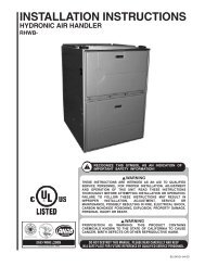
8.0 REFRIGERANT CONNECTIONSKeep the coil connections sealed until refrigerant connections are to be made. See theInstallation Instructions for the outdoor unit for details on line sizing, tubing installation,and charging information.Coil is shipped with a low (5 - 10 PSIG) pressure charge of dry nitrogen. Evacuate thesystem before charging with refrigerant.Install refrigerant tubing so that it does not block service access to the front of the unit.Nitrogen should flow through the refrigerant lines while brazing.Use a brazing shield to protect the cabinet’s paint from being damaged by torch flames.After the refrigerant connections are made, seal the gap around the connections withpressure sensitive gasket. If necessary, cut the gasket into two pieces for a better seal.8.1 TEV SENSING BULBIMPORTANT: DO NOT perform any soldering with the TEV bulb attached to any line.After soldering operations have been completed, clamp the TEV bulb securely on thesuction line at the 10 to 2 o’clock position with the strap provided in the parts bag.Insulate the TEV sensing bulb and suction line with the provided pressure sensitive insulation(size 4” x 7”) and secure with provided wire ties.IMPORTANT: TEV sensing bulb should be located on a horizontal section of suctionline, just outside of coil box.8.2 CONDENSATE DRAIN TUBINGConsult local codes or ordinances for specific requirements.IMPORTANT: When making drain fitting connections to the drain pan, use a thin layer ofTeflon paste, silicone or Teflon tape and install hand tight.IMPORTANT: When making drain fitting connections to drain pan, do not overtighten.Overtightening fittings can split pipe connections on the drain pan.• Install drain lines so they do not block service access to front of the unit. Minimumclearance of 24 inches is required for filter, coil or blower removal and service access.• Make sure unit is level or pitched slightly toward primary drain connection so thatwater will drain completely from the pan. (See Figure 20.)• Do not reduce drain line size less than connection size provided on condensate drainpan.• All drain lines must be pitched downward away from the unit a minimum of 1/8” perfoot of line to ensure proper drainage.• Do not connect condensate drain line to a closed or open sewer pipe. Run condensateto an open drain or outdoors.• The drain line should be insulated where necessary to prevent sweating and damagedue to condensate forming on the outside surface of the line.27
• Make provisions for disconnecting and cleaning of the primary drain line should itbecome necessary. Install a 3 in. trap in the primary drain line as close to the unit aspossible. Make sure that the top of the trap is below connection to the drain pan toallow complete drainage of pan (See Figure 21).FIGURE 21CONDENSATE DRAIN TRAPDO NOT OPERATE UNIT WITHOUTCONDENSATE DRAIN TRAP.UNIT3''3''• Auxiliary drain line should be run to a place where it will be noticeable if it becomesoperational. Occupant should be warned that a problem exists if water should beginrunning from the auxiliary drain line.• Plug the unused drain connection with the plugs provided in the parts bag, using athin layer of teflon paste, silicone or teflon tape to form a water tight seal.• Test condensate drain pan and drain line after installation is complete. Pour waterinto drain pan, enough to fill drain trap and line. Check to make sure drain pan isdraining completely, no leaks are found in drain line fittings, and water is drainingfrom the termination of the primary drain line.8.3 DUCT FLANGESDO NOT OVERTIGHTEN DRAIN FITTINGUNIT MUST BE SLIGHTLY INCLINEDTOWARD DRAIN CONNECTION.Field-installed duct flanges (4 pieces) are shipped with units. Install duct flanges asneeded on top of the unit. (See Figure 3.)9.0 AIR FILTER (Not Factory-Installed)If a remote filter is installed, it should be sized for a maximum of 300 feet/min. air velocityfor the CFM required.IMPORTANT: Do not operate system without a filter. A filter is required to protect thecoil, blower and internal parts from excessive dirt and dust.10.0 SEQUENCE OF OPERATION10.1 Cooling (cooling only or heat pump)• When the thermostat “calls for cooling,” the circuit between R, G and Y is completed,causing the blower to energize. This circuit also closes the contactor (CC) in the outdoorunit starting the compressor (COMP) and outdoor fan motor (OFM).10.2 Heating (electric heat only)• When the thermostat “calls for heat,” the circuit between R and W 1 is completed, andthe heater sequencer (HR 1 ) is energized. A time delay will follow then: The heatingelements (HE) and the indoor blower motor (IBM) will come on. Units with a secondheater sequencer (HR 2 ) can be connected with the first sequencer (HR 1 ) to W on thethermostat sub-base or connected to a second stage W 2 on the sub-base.W 1 on the furnace board MUST be connected for heating blower operation.28
10.3 Heating (heat pump)• When the thermostat “calls for heat,” the circuits between R and G are completed.Circuit R and B energizes the reversing valve (RV) switching it to the heating position(remains energized as long as system switch is in “heat” position). Circuit R and Yenergizes the contactor (CC) starting the outdoor fan motor (OFM), compressor(COMP), and the indoor blower motor (IBM).• If the room temperature should continue to fall, circuit R and W2 is completed by thesecond-stage heat room thermostat. Circuit R-W2 energizes a heat sequencer (HR1).The completed circuit will energize supplemental electric heat. Units with a secondheater sequencer (HR2) can be connected with first sequencer (HR1) to W2 on thermostator connected to a third heating stage W3 on the thermostat sub-base. A light onthe thermostat indicates when supplemental heat is being energized.10.4 DEFROST• For sequence of operation for defrost controls, see outdoor heat pump installationinstructions.• Supplemental heat during defrost can be provided by connecting the purple (PU) pigtailin the outdoor unit to P on the indoor unit control board. This will complete the circuitbetween R and W through a set of contacts in the defrost relay (DR) when theoutdoor heat pump is in defrost. This circuit, if connected, will temper air being dischargedfrom the indoor unit during defrost.• Defrost heat control (DHC) is wired in series in the circuit described above on unitswhere the supplemental heat is more than would be required to offset the defrostcooling capacity. Defrost heat control (DHC) is provided on the same modelsdescribed above having watt restrictors.• When the outdoor unit goes into defrost, the circuit between R and W is completedthrough a set of contacts on the defrost relay (DR) in series with the contacts on thedefrost heat control (DHC). Purple (PU) pigtails on the indoor unit and outdoor unitsmust be connected to make circuit. During defrost, the defrost heat control (DHC)senses the air temperature leaving the indoor unit and cycles the supplemental electricheat to maintain comfort (75° to 85°) air temperature and prevent objectionablecold air during defrost. This limits the electric heat output to the minimum required, toconserve energy and prevent the thermostat from being satisfied with electric heatand preventing completion of the defrost cycle.• For most economical operation, if cold air is not of concern during defrost, the purplewire can be left disconnected. Supplemental heat will only be energized by a call fromsecond stage room thermostat.10.5 EMERGENCY HEAT (Heating of Heat Pump)• If selector switch on thermostat is set to the emergency heat position, the heat pumpwill be locked out of the heating circuit, and all heating will be electric heat. Jumpershould be placed between W2 and E on the thermostat sub-base so that the electricheat control will transfer to the first stage heat on the thermostat. This will allow theindoor blower to cycle on and off with the electric heat when the fan switch is in theauto position.10.6 ROOM THERMOSTAT (ANTICIPATOR SETTING)See instructions with outdoor section, condensing unit or heat pump for recommendedroom thermostats.• On units with one electric heat sequencer (HR1) (see wiring diagram on unit), heatanticipator setting should be .16.• On units with two electric heat sequencers (HR1 & HR2) (see wiring diagram on unit),heat anticipator setting should be .32 if both are connected to same stage on thermostat.Setting should be .16 if (HR1 &HR2) are connected to separate stages.NOTE: Some thermostats contain a fixed, non-adjustable heat anticipator. Adjustment isnot permitted.• The thermostat should be mounted 4 to 5 feet above the floor on an inside wall of theliving room or a hallway that has good air circulation from the other rooms being controlledby the thermostat. It is essential that there be free air circulation at the locationof the same average temperature as other rooms being controlled. Movement of airshould not be obstructed by furniture, doors, draperies, etc. The thermostat shouldnot be mounted where it will be affected by drafts, hot or cold water pipes or air ductsin walls, radiant heat from fireplace, lamps, the sun, T.V. or an outside wall. Seeinstruction sheet packaged with thermostat for mounting and installation instructions.NOTE: Some thermostats, particularly solid-state digital types, contain fixed, nonadjustableheat anticipators and adjustment is not permitted.29
11.0 CALCULATIONS11.1 CALCULATING TEMPERATURE RISE• The formula for calculating air temperature rise for electric resistance heat is:3.16 x WattsTemperature Rise °F =CFMWhere: 3.16 = Constant, CFM = <strong>Air</strong>flow11.2 CALCULATING BTUH HEATING CAPACITY• The formula for calculating BTUH heating capacity for electric resistance heat is:BTUH Heating = Watts x 3.412Where: 1 kW = 1000 Watts, 3.412 = Btuh/Watt11.3 CALCULATING AIRFLOW CFM• The formula for calculating airflow using temperature rise and heating BTUH for unitswith electric resistance heat is:Heating BTUHCFM = 1.08 x Temp. Rise11.4 CALCULATING CORRECTION FACTOR• For correction of electric heat output (kW or BTUH) or temperature rise at voltagesother than rated voltage multiply by the following correction factor:Correction Factor =Applied Voltage 2Rated Voltage 230
12.0 PRE-START CHECKLISTPRE-START CHECKLIST❍ YES❍ NO❍ YES❍ NO❍ YES❍ NO❍ YES❍ NO❍ YES❍ NOIs unit properly located, level, secure and serviceable?Has auxiliary pan been provided under the unit withseparate drain? (Units installed above a finishedceiling).Is condensate line properly sized, run, trapped,pitched and tested?Is ductwork correctly sized, run, taped and insulated?Have all cabinet openings and wiring been sealedwith caulking?❍ YES❍ NO❍ YES❍ NO❍ YES❍ NO❍ YES❍ NO❍ YES❍ NO❍ YES❍ NOIs the filter clean, in place and of adequate size?Is the wiring tight, correct and to the wiring diagram?Is the unit properly grounded and protected (fused)?Is the thermostat heat anticipator been set properly?Is the unit circuit breaker(s) rotated properly “on” up- “off” down?Are the unit circuit breaker(s) line lug cover(s) inplace?❍ YES❍ NOAre all access panels in place and secure?Refer to outdoor unit installation instructions for systemstart-up instructions and refrigerant charging instructions.13.0 MAINTENANCEFor continuing high performance, and to minimize possible equipment failure, it isessential that periodic maintenance be performed on this equipment. Consult your localdealer as to the proper frequency of maintenance and the availability of a maintenancecontract.IMPORTANT: Before performing any service or maintenance procedures, read all“WARNINGS” listed in these installation instructions.! WARNINGUnits with circuit breaker(s) meet requirements as a service disconnectswitch, however, if access is required to the line side (covered) of the circuitbreaker, this side of the breaker(s) will be energized with the breaker(s) deenergized.Contact with the line side can cause electrical shock resulting inpersonal injury or death.<strong>31</strong>
13.1 AIR FILTER (Not Factory Installed)Check the system filter every ninety days or as often as found to be necessary and ifobstructed, clean or replace at once.IMPORTANT: Do not operate the system without a filter in place.13.2 INDOOR COIL - DRAIN PAN - DRAIN LINEInspect the indoor coil once each year for cleanliness and clean as necessary. It is necessaryto remove the filter and check the return air side of the coil for debris.IMPORTANT: Do not use caustic household drain cleaners, such as bleach, in the condensatepan or near the indoor coil. Drain cleaners will quickly damage the indoor coil.CAUTIONIn compliance with recognized codes, it is recommended that an auxiliarydrain pan be installed under all evaporator coils or units containing evaporatorcoils that are located in any area of a structure where damage to the buildingor building contents may occur as a result of an overflow of the coil drain panor a stoppage in the primary condensate drain piping. See accessory sectionin this manual for secondary horizontal drain pan RXBM-ABXX.13.3 BLOWER MOTOR AND WHEELInspect the blower motor and wheel for cleanliness. With the system air filter in place, itshould be several years before it would become necessary to clean the blower motorand wheel.• If it becomes necessary to remove the blower assembly from the unit, see instructionson removal and disassembly of motor, blower and heater parts.• The blower motor and wheel may be cleaned by using a vacuum with a soft brushattachment. Remove grease with a mild solvent such as hot water and detergent. Becareful not to disturb the balance weights (clips) on the blower wheel blades. Do notdrop or bend wheel as balance will be affected.13.4 LUBRICATIONThe blower motor sleeve bearings are pre-lubricated by the motor manufacturer and donot have oiling ports. Motor should be run for an indefinite period of time without additionallubrication.13.5 BLOWER ASSEMBLY REMOVAL AND REPLACEMENTRemoving the blower assembly is not required for normal service and maintenance.Removal is necessary for replacement of components such as motor, blower wheel.After extended use, removal of the blower assembly may become necessary for a thoroughcleaning of the blower motor and wheel.! WARNINGIf removal of the blower assembly is required, all disconnect switches supplyingpower to the airhandler must be de-energized and locked (if not in sight ofunit) so the field power wires can be safely removed from the blower assembly.Failure to do so can cause electrical shock resulting in personal injury ordeath.32
• Mark field power supply wiring (for replacement) attached to terminal block or circuitbreaker(s) on blower assembly. Remove wiring from terminal block or circuit breaker(s).• Mark low voltage control wiring (for replacement) where attached to unit control terminalson left side of blower housing.• Remove a screw holding blower assembly to front channel of cabinet and pull blowerassembly from cabinet.• To replace blower assembly, slide blower assembly into blower deck. Make sureblower assembly engages lances in deck properly. If assembly hangs up, check tomake sure top and bottom are lined up in proper locations.• Slide blower assembly to back of cabinet and make sure it is completely engaged.• Replace two screws holding blower assembly to front channel of cabinet. Take carenot to strip screws, just snug into place.• Replace low voltage control wiring with wire nuts and make sure wiring is to wiringdiagram and a good connection has been made.• Replace field power wiring to terminal block or circuit breaker(s) on control area ofblower assembly. Make sure wires are replaced as they were, check wiring diagram ifnecessary. Tighten supply power wiring securely to terminals lugs.• Make sure wiring is within cabinet and will not interfere with access door. Make sureproper separation between low voltage control wiring and field power wiring has beenmaintained.• Replace blower assembly control access panel before energizing equipment.13.6 MOTOR REPLACEMENTWith the blower assembly removed, the indoor blower motor can be removed andreplaced using the following procedure:• Remove motor leads from the motor high and low voltage plugs. Note the lead locationsfor ease of re-assembly.• Loosen the set screw holding the blower wheel onto the motor shaft. The shaftextends through the blower hub so that a wrench can be used on the extended shaftto break the shaft loose if necessary. Be careful not to damage the shaft. Use awheel puller on the groove in the hub if necessary.• Loosen the bolt holding the wire motor band around the motor shell and pull themotor from the motor mount. Note the motor position in the mount for re-assembly.• To re-assemble, insert the motor shaft through the hub in the blower wheel and orientthe motor to original position.• For proper motor cooling, it is important that the motor be mounted the same as theoriginal, as far into the blower as practical.• The dimension from the face of the motor end plate (shaft end) to the first wire on themotor mount band around the shell should be:DIMENSION TONNAGE CABINET SIZE1 3 /32" 1 1 /2 & 2 171 1 /2" 2 1 /2 & 3 172 1 /2" 3, 3 1 /2 & 4 212 7 /8" 5 24• With motor held to above position and motor lead plugs oriented to the original position(the wire connectors on the motor must point straight to the supply air end of theunit and away from the return air [filter] end of the unit). Securely tighten the bolt onthe mount band to the motor shell.• Turn the motor shaft so that the flat on the shaft is located under blower wheelsetscrew, and the blower wheel is centered in the blower housing with the same distanceon each side between the inlet venturi and the outside of the blower wheel.• Re-assemble the motor wiring (high and low voltage plugs) into the motor.IMPORTANT: DO NOT FORCE POWER PLUG INTO THE MOTOR CONNECTORBACKWARDS. The A.C. power plug to the motor has locking tabs. It has beenproven that by applying excessive force to the A.C. cable half of the connector it ispossible to force the connector in backwards. It will not seat and “click” properly butwill make connection. If A.C. power is applied with the connector reversed the motorwill be immediately destroyed.33
FIGURE 22INTERNAL MOTOR PLUG AND SOCKET13.7 ECM CONTROL MODULE REPLACEMENTAlways take the following steps before replacing the control module on the end of theECM indoor blower motor.1. HAVE THE CORRECT REPLACEMENT MODULE. These controls are factory programmedfor specific operating modes. Even though they look alike, different modulesmay have different CFM characteristics.IMPORTANT: Using the wrong control module voids all product warranties and may produceunexpected results.! WARNINGAlways have 240 volt power turned off to the furnace before attempting anyreplacement of the motor or control module. Failure to do so may result in seriousequipment damage, personal injury or death.2. Turn off power to the equipment. Wait at least 5 minutes after disconnecting ACpower before opening the motor.3. While not necessary, it may prove easier to remove the complete blower assemblyfrom the furnace. Unplug the two cable connectors to the motor. There are latcheson each connector. DO NOT PULL ON THE WIRES. TO REMOVE THE 16 PINPLUG, SQUEEZE THE PIN LATCH. The plugs remove easily when properlyreleased.FIGURE 23ECM MOTOR COMPONENTSFIGURE 24MOTOR ALIGNMENT PIN34
4. Locate the two standard 1/4" hex head bolts on the flat end of the motor controlmodule casting. Remove these bolts from the motor while holding the control module.DO NOT REMOVE TWO SCREWS WITH TORX HEADS.5. The control module is still connected to the motor by a plug and cable. Carefullyrotate the control so as to gain access to the plug on the cable end. Squeeze therelease latch and gently pull the plug out of the control module. DO NOT PULL ONTHE WIRES. GRIP THE PLUG ONLY.6. The control module is now completely detached from the motor. Use an ohmmeterto measure the resistance from each motor lead (in the motor plug just removed) tothe motor shell. This resistance must be greater than 100K ohms. Always measureto the unpainted motor end plate. If any motor lead fails this test DO NOT INSTALLTHE NEW CONTROL MODULE.7. Verify that the replacement control module is correct. Place the new module next tothe motor and carefully insert the plug that was removed in step 5. BE SURE THEPLUG LATCHES. IT SHOULD CLICK INTO PLACE.8. Install the new control module back on the motor. Carefully engage the alignmentpin into the appropriate mating motor hole.9. Replace the two 1/4" hex head bolts. Tighten the bolts snugly. DO NOT OVERTIGHTEN.IMPORTANT: Before replacing the blower motor assembly, check the installation for anyapplication fault that might have caused the motor or control module to fail. Water damagecould show as corrosion on the inside or outside of the casting. If so, run a MoistureCheck.10. Install the blower motor assembly back into the furnace. Follow the manufacturer’ssuggested procedures.11. Plug the 16 pin connector into the motor. The connector is keyed. Be sure the connectoris properly seated and latched.12. Plug the 5 pin connector into the motor. The connector is keyed. Be sure the connectoris properly seated and latched. OBSERVE THE PROPER ORIENTATION.DO NOT FORCE THE CONNECTOR. It plugs in very easily when properly oriented.! CAUTION<strong>Rev</strong>ersing the 5-pin connector on the ECM motor causes immediate failure ofthe control module.13. Final installation check. Be sure the motor is installed as follows.a. Set the motor into the blower housing as originally provided from the manufacturer.b. Do not allow the motor mount to cover the motor vent openings.c. Do not attach the motor mount to the motor electronics compartment.d. The motor connectors should be straight down.e. Have appropriate drip loops formed in the harnesses.14. Restore 230 volt power to the system. Verify that the new motor control moduleworks properly.13.8 BLOWER WHEEL REPLACEMENTWith the blower assembly removed and the motor assembly removed (see aboveinstructions), remove the two screws holding the blower wrap (cutoff) to the blowersides.IMPORTANT: It is not necessary to remove heating element(s), if provided, to removethe blower wheel.35
• With wrap (cutoff) screws removed, cut off end of blower wrap will spring up. Liftingwrap blower wheel is removed through the discharge opening in the blower housing.• To replace, make sure wheel is oriented properly with hub to the opposite side fromthe motor. Lift blower wrap and insert blower wheel through discharge opening in theblower housing.• Hold blower wrap down into position and replace two screws holding blower wrap toblower sides.• See motor replacement and blower assembly instructions for remaining assemblyprocedure.14.0 REPLACEMENT PARTSAny replacement part used to replace parts originally supplied on equipment must bethe same as or an approved alternate to the original part supplied. The manufacturer willnot be responsible for replacement parts not designed to physically fit or operate withinthe design parameters the original parts were selected for.These parts include but are not limited to: Circuit breakers, heater controls, heater limitcontrols, heater elements, motor, motor capacitor, blower relay, control transformer,blower wheel, filter, indoor coil and sheet metal parts.When ordering replacement parts, it is necessary to order by part number and includewith the order the complete model number and serial number from the unit data plate.(See parts list for unit component part numbers).15.0 ACCESSORIES - KITS - PARTS• Combustible Floor Base RXHB-17, RXHB-21, RXHB-24 (for standard units) fordownflow applications, see section of this manual covering combustible floor base.Combustible FloorModel Cabinet SizeBase Model Number17 RXHB-1721 RXHB-2124 RXHB-2436
• External Filter Base RXHF- (See Figure 23)Model Cabinet Size Filter Size Part Number A B17 16 x 20 [406 x 508] RXHF-17 Accommodate 15.70 17.5021 20 x 20 [508 x 508] RXHF-21 1” or 2” 19.20 21.00filter24 25 x 20 [635 x 508] RXHF-24 22.70 25.50FIGURE 25EXTERNAL FILTER BASE: RXHF-37
• External Filter Rack: RXHF-B (See Figure 24)Model Cabinet Size Filter Size Part Number A B17 16 x 20 RXHF-B17 16.90 20.77Accommodate21 20 x 20 RXHF-B21 20.40 20.771” filter24 25 x 20 RXHF-B24 25.00 21.04FIGURE 26EXTERNAL FILTER RACK: RXHF- B17, B21, B241.50➦➦BA• Horizontal Adapter Kit RXHH-This horizontal adapter kit is used to convert Upflow/Downflow only models to horizontalflow. See the following table to order proper horizontal adapter kit.Coil Model Horizontal Adapter KitModel Number (Single Qty.)Horizontal Adapter KitModel Number (10-pak Qty.)2414 RXHH-A01 RXHH-A01x102417 RXHH-A02 RXHH-A02x103617/3621 RXHH-A03 RXHH-A03x103821/4821/4824 RXHH-A04 RXHH-A04x106024 RXHH-A05 RXHH-A05x10• Auxiliary Horizontal Unit Overflow Pan Accessory RXBM-NominalAuxiliary Horizontal OverflowCoolingPan AccessoryCapacity TonModel Number1 1 /2 - 3 RXBM-AC483 1 /2 - 5 RXBM-AC6138
40 CM 0610