Tm 9-2330-203-14&p technical manual and - Combatindex.com
Tm 9-2330-203-14&p technical manual and - Combatindex.com
Tm 9-2330-203-14&p technical manual and - Combatindex.com

Create successful ePaper yourself
Turn your PDF publications into a flip-book with our unique Google optimized e-Paper software.
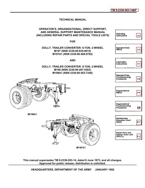
TECHNICAL MANUAL<br />
OPERATOR’S, ORGANIZATIONAL, DIRECT SUPPORT,<br />
AND GENERAL SUPPORT MAINTENANCE MANUAL<br />
(INCLUDING REPAIR PARTS AND SPECIAL TOOLS LISTS)<br />
FOR<br />
DOLLY, TRAILER CONVERTER: 6-TON, 2-WHEEL<br />
M197 (NSN <strong>2330</strong>-00-835-8615)<br />
M197A1 (NSN <strong>2330</strong>-00-569-0782)<br />
AND<br />
DOLLY, TRAILER CONVERTER: 8-TON, 2-WHEEL<br />
M198 (NSN <strong>2330</strong>-00-287-5<strong>203</strong>)<br />
M198A1 (NSN <strong>2330</strong>-00-563-7248)<br />
This <strong>manual</strong> supersedes TM 9-<strong>2330</strong>-<strong>203</strong>-14, dated 8 June 1973, <strong>and</strong> all changes.<br />
Approved for public release; distribution is unlimited.<br />
HEADQUARTERS, DEPARTMENT OF THE ARMY JANUARY 1992<br />
TM 9-<strong>2330</strong>-<strong>203</strong>-14&P
CHAPTER 1 INTRODUCTION<br />
Page<br />
Section I General Information ........................................................................................................ 1-1<br />
Section II. Equipment Description <strong>and</strong> Data .................................................................................... 1-2<br />
CHAPTER 2 OPERATING INSTRUCTIONS<br />
Section I........ Description <strong>and</strong> Use of Operator’s Controls <strong>and</strong> Indicators............................................ 2-1<br />
Section II, Organizational Preventive Maintenance Checks <strong>and</strong><br />
Services (PMCS) ............................................................................................................ 2-3<br />
Section III...... Operation Under Usual Conditions 2-8<br />
Section IV. Operation Under Unusual Conditions ............................................................................. 2-13<br />
CHAPTER 3 OPERATOR MAINTENANCE<br />
Section I. Lubrication Instructions................................................................................................... 3-1<br />
Section II. Operator/Crew Troubleshooting Procedures.................................................................. 3-6<br />
Approved for public release distribution is unlimited.<br />
* This <strong>manual</strong> supersedes TM 9-<strong>2330</strong>-<strong>203</strong>-14, dated 8 June 1973, <strong>and</strong> all changes.
TM 9-<strong>2330</strong>-<strong>203</strong>-14&P<br />
TABLE OF CONTENTS (Con’t)<br />
Illus<br />
Fig Page<br />
CHAPTER 4 ORGANIZATIONAL MAINTENANCE<br />
Section I. Repair Parts; Special Tools; Test, Measurement, <strong>and</strong><br />
Diagnostic Equipment (TMDE); <strong>and</strong> Support Equipment ............................................... 4-1<br />
Section II. Service Upon Receipt ..................................................................................................... 4-2<br />
Section III. Organizational Preventive Maintenance Checks <strong>and</strong><br />
Services (PMCS) ............................................................................................................ 4-3<br />
Section IV. Organizational Troubleshootinq Procedures .................................................................. 4-6<br />
Section V. Electrical System Maintenance....................................................................................... 4-13<br />
Section VI. Axle Maintenance ........................................................................................................... 4-25<br />
Section VII. Brake System Maintenance............................................................................................ 4-28<br />
Section VIII. Wheels, Hubs, <strong>and</strong> Brakedrums Maintenance ............................................................... 4-88<br />
Section IX. Frame <strong>and</strong> Towing Attachments Maintenance ............................................................... 4-96<br />
Section X. Springs <strong>and</strong> Radius Rods Maintenance ......................................................................... 4-113<br />
Section XI. Body Maintenance .......................................................................................................... 4-122<br />
Section XII. Accessory Items Maintenance........................................................................................ 4-124<br />
Section XIII. Preparation for Storage or Shipment .............................................................................. 4-126<br />
CHAPTER 5 DIRECT SUPPORT AND GENERAL SUPPORT MAINTENANCE<br />
Section I. Brake System Maintenance............................................................................................ 5-1<br />
Section II. Wheels, Hubs, <strong>and</strong> Brakedrums Maintenance ............................................................... 5-3<br />
Section III. Frame <strong>and</strong> Towing Attachments Maintenance ............................................................... 5-4<br />
APPENDIX A REFERENCES...................................................................................................................... A-i<br />
APPENDIX B MAINTENANCE ALLOCATION CHART.............................................................................. B-1<br />
APPENDIX C COMPONENTS OF END ITEM AND BASIC ISSUE ITEMS LISTS .................................... C-1<br />
APPENDIX D ADDITIONAL AUTHORIZATION LIST................................................................................. D-1<br />
APPENDIX E EXPENDABLE/DURABLE SUPPLIES AND MATERIALS LIST......................................... E-1<br />
APPENDIX F REPAIR PARTS AND SPECIAL TOOLS LISTS.................................................................. F-1<br />
Section I. Introduction ..................................................................................................................... F-1<br />
Section II. Repair Parts List<br />
GROUP 06 ELECTRICAL SYSTEM<br />
0609 - LIGHTS ........................................................................................................................... 1-1<br />
STOP, TURN, AND TAILLAMP ASSEMBLY (M197A1 AND M198A1).......................... 1 1-1<br />
0613 - HULL OR CHASSIS WIRING HARNESS....................................................................... 2-1<br />
INTERVEHICULAR CABLE ASSEMBLIES ............................................................................... 2 2-1<br />
REAR CHASSIS WIRING HARNESS AND MOUNTING HARDWARE<br />
(M197A1 AND M198A1)............................................................................................................. 3 3-1<br />
ii
TM 9-<strong>2330</strong>-<strong>203</strong>-14&P<br />
TABLE OF CONTENTS (Con’t)<br />
Illus<br />
Fig Page<br />
GROUP 11 REAR AXLE<br />
1100 - REAR AXLE ASSEMBLY................................................................................................ 4-1<br />
NONDRIVING VEHICULAR AXLE ................................................................................. 4 4-1<br />
GROUP 12 BRAKES<br />
1202 - SERVICE BRAKES......................................................................................................... 5-1<br />
BRAKES (M197 AND M198) .......................................................................................... 5 5-1<br />
BRAKE ASSEMBLY (M197A1 AND M198A1, EARLY MODELS).................................. 6 6-1<br />
SERVICE BRAKE ASSEMBLY (M197A1 AND M198A1, LATE MODELS).................... 7 7-1<br />
1204 - HYDRAULIC BRAKE SYSTEM ...................................................................................... 8-1<br />
HYDRAULIC WHEEL CYLINDER (M197A1 AND M198A1) .......................................... 8 8-1<br />
HYDRAULIC BRAKE, MASTER CYLINDER (M197A1 AND M198A1).......................... 9 9-1<br />
BRAKE HYDRAULIC SYSTEM (M197A1 AND M198A1) 10 10-1<br />
1208 - AIRBRAKE SYSTEM ...................................................................................................... 11-1<br />
AIRBRAKE SYSTEM (M197 AND M198).....................................................................11 11-1<br />
AIRBRAKE SYSTEM (M197A1 AND M198A1)............................................................12 12-1<br />
BRAKE LINE COUPLING AND HOSE ASSEMBLY.....................................................13 13-1<br />
AIR FILTER (M197A1 AND M198A1)...........................................................................14 14-1<br />
EMERGENCY RELAY VALVE .....................................................................................15 15-1<br />
AIR CHAMBER ASSEMBLY (M197 AND M198)..........................................................16 16-1<br />
AIR CHAMBER (M197A1 AND M198A1) .....................................................................17 17-1<br />
GROUP 13 WHEELS AND TRACKS<br />
1311 - WHEEL ASSEMBLY....................................................................................................... 18-1<br />
WHEEL AND HUB.......................................................................................................... 18 18-1<br />
1313 - TIRES, TUBES, TIRE CHAINS....................................................................................... 19-1<br />
TIRES AND TUBES........................................................................................................ 19 19-1<br />
GROUP 15 FRAME, TOWING ATTACHMENTS, DRAWBARS, AND ARTICULATION SYSTEMS<br />
1501 - FRAME ASSEMBLY ....................................................................................................... 20-1<br />
LANDING LEG BRACE AND SPRING BUMPER .......................................................... 20 20-1<br />
1503 - PINTLES AND TOWING ATTACHMENTS .................................................................... 21-1<br />
LUNETTE AND SAFETY CHAIN.................................................................................... 21 21-1<br />
1506 - FIFTH WHEEL ................................................................................................................ 22-1<br />
FIFTH WHEEL ASSEMBLY ........................................................................................... 22-1<br />
1507 - LANDING GEAR, LEVELING JACKS............................................................................. 22 23-1<br />
LEVELING JACK ............................................................................................................ 23 23-1<br />
GROUP 16 SPRINGS AND SHOCK ABSORBERS<br />
1601 - SPRINGS........................................................................................................................ 24-1<br />
SPRINGS (M197 AND M198)......................................................................................... 24 24-1<br />
SPRINGS AND RADIUS RODS (M197A1 AND M198A1) ............................................. 25 25-1<br />
GROUP 18 BODY, CAB, HOOD, AND HULL<br />
1808 - STOWAGE RACKS, BOXES, STRAPS, CARRYING CASES,<br />
CABLE REELS, HOSE REELS, ETC. ............................................................................ 26-1<br />
STOWAGE RACK .......................................................................................................... 26 26-1<br />
iii
TABLE OF CONTENTS (Con’t)<br />
GROUP 22 BODY, CHASSIS, AND HULL ACCESSORY ITEMS<br />
TM 9-<strong>2330</strong>-<strong>203</strong>-14&P<br />
Illus<br />
Fig Page<br />
2202- ACCESSORY ITEMS....................................................................................................... 27-1<br />
REFLECTORS................................................................................................................ 27 27-1<br />
2210 - DATA PLATES AND INSTRUCTION HOLDERS........................................................... 28-1<br />
DATA PLATES ............................................................................................................... 28 28-1<br />
GROUP 94 REPAIR KITS<br />
9401 - REPAIR KITS.................................................................................................................. KITS-1<br />
REPAIR KITS............................................................................................................KITS KITS-1<br />
GROUP 95 GENERAL USE STANDARDIZED PARTS<br />
9501 - BULK MATERIEL......................................................................................................... BULK-1<br />
BULK MATERIEL.................................................................................................BULK BULK-1<br />
Section IlI. Special Tools List<br />
GROUP 26 TOOLS AND TEST EQUIPMENT<br />
2604 - SPECIAL TOOLS......................................................................................................... 29-1<br />
SPECIAL TOOLS ........................................................................................................... 29-1<br />
Section IV. Cross-reference Indexes<br />
NATIONAL STOCK NUMBER INDEX ............................................................................ I-1<br />
PART NUMBER INDEX.................................................................................................. I-5<br />
FIGURE AND ITEM NUMBER INDEX............................................................................ 1-17<br />
APPENDIX G. ILLUSTRATED LIST OF MANUFACTURED ITEMS........................................................ G-1<br />
APPENDIX H. TORQUE LIMITS............................................................................................................... H-1<br />
INDEX ............................................................................................................................. Index 1<br />
iv
CHAPTER 1<br />
INTRODUCTION<br />
Section I. GENERAL INFORMATION<br />
TM 9-<strong>2330</strong>-<strong>203</strong>-14&P<br />
Page<br />
Paragraph Title Number<br />
Destruction of Army Materiel to Prevent Enemy Use...................................................................................................... 1-1<br />
Maintenance Forms, Records, <strong>and</strong> Reports ................................................................................................................... 1-1<br />
Preparation for Storage or Shipment............................................................................................................................... 1-1<br />
Reporting Equipment Improvement Re<strong>com</strong>mendations (EIRs) ...................................................................................... 1-1<br />
Scope .............................................................................................................................................................................. 1-1<br />
1-1. SCOPE.<br />
a. Type of Manual. Operator’s, Organizational, Direct Support, <strong>and</strong> General Support Maintenance Manual<br />
(Including Repair Parts <strong>and</strong> Special Tools Lists).<br />
b. Equipment Names <strong>and</strong> Model Numbers. Dolly, Trailer Converter: 6-Ton, 2-Wheel, M197 <strong>and</strong> M197A1; Dolly,<br />
Trailer Converter: 8-Ton, 2-Wheel, M198 <strong>and</strong> M198A1.<br />
c. Purpose of Equipment. Converts semitrailers to full trailers so that semitrailers can be towed by vehicles<br />
without a fifth wheel.<br />
1-2. MAINTENANCE FORMS, RECORDS, AND REPORTS.<br />
Department of the Army forms <strong>and</strong> procedures used for equipment maintenance will be those prescribed by DA<br />
Pam 738-750, The Army Maintenance Management System (TAMMS).<br />
1-3. DESTRUCTION OF ARMY MATERIEL TO PREVENT ENEMY USE.<br />
For information on destruction of Army materiel to prevent enemy use, refer to TM 750-244-6.<br />
1-4. PREPARATION FOR STORAGE OR SHIPMENT.<br />
For information on preparing the trailer converter dollies for storage or shipment, refer to Chapter4, Section XIII.<br />
1-5. REPORTING EQUIPMENT IMPROVEMENT RECOMMENDATIONS (EIRs).<br />
If your trailer converter dolly needs improvement, let us know. Send us an EIR. You, the user, are the only one<br />
who can tell us what you don’t like about your equipment. Let us know why you don’t like the design or performance. Put<br />
it on an SF 368 (Product Quality Deficiency Report). Mail it to us at: Comm<strong>and</strong>er, U.S. Army Tank-Automotive<br />
Comm<strong>and</strong>, ATTN: AMSTA-MP, Warren, MI 48397-5000. We’ll send you a reply.<br />
1-1
Section II. EQUIPMENT DESCRIPTION AND DATA<br />
TM 9-<strong>2330</strong>-<strong>203</strong>-14&P<br />
Page<br />
Paragraph Title Number<br />
Differences Between Models.................................................................................................................................. 1-8<br />
Equipment Characteristics, Capabilities <strong>and</strong> Features........................................................................................... 1-2<br />
Equipment Data...................................................................................................................................................... 1-10<br />
Location <strong>and</strong> Contents of Data Plates.................................................................................................................... 1-7<br />
Location <strong>and</strong> Description of Major Components .................................................................................................... 1-3<br />
1-6. EQUIPMENT CHARACTERISTICS, CAPABILITIES, AND FEATURES.<br />
a. The trailer converter dollies allow vehicles with towing pintles to tow semitrailers,<br />
b. Up to 12, 000 lb (5448kg) can towed using the M197 <strong>and</strong> M197A1 dollies. Up to 16, 000 lb (7264kg) can be towed<br />
using the M198 <strong>and</strong> M198A1 dollies.<br />
c. Maximum towing speeds are 30 mi/h (48 km/h) highway <strong>and</strong> 20 mi/h (32 km/h) cross-country.<br />
d. Major features of the dollies include:<br />
(1) Intervehicular airbrake hoses receive air from towing vehicle for use by dolly <strong>and</strong> semitrailer brake system.<br />
(2) Intervehicular electrical cables receive 12- or 24-volt direct current to power semitrailer lights.<br />
(3) L<strong>and</strong>ing leg supports dolly when not coupled to towing vehicle.<br />
(4) M198 <strong>and</strong> M198A1 have a two-position lunette.<br />
(5) Military pneumatic tires with nondirectional cross-country tread design.<br />
1-2
1-7. LOCATION AND DESCRIPTION OF MAJOR COMPONENTS.<br />
1-3<br />
TM 9-<strong>2330</strong>-<strong>203</strong>-14&P