Continuous Blowdown Valves
Continuous Blowdown Valves
Continuous Blowdown Valves
- No tags were found...

You also want an ePaper? Increase the reach of your titles
YUMPU automatically turns print PDFs into web optimized ePapers that Google loves.
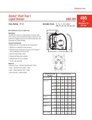
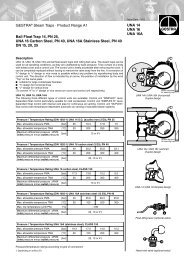
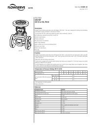
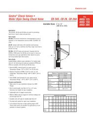
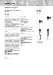
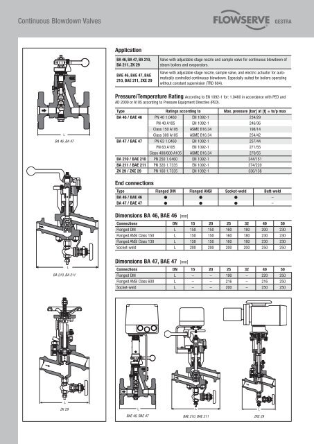
<strong>Continuous</strong> <strong>Blowdown</strong> <strong>Valves</strong>ApplicationBA 46, BA 47, BA 210,BA 211, ZK 29BAE 46, BAE 47, BAE210, BAE 211, ZKE 29Valve with adjustable stage nozzle and sample valve for continuous blowdown ofsteam boilers and evaporators.Valve with adjustable stage nozzle, sample valve, and electric actuator for automaticallycontrolled continuous blowdown. Especially suited for boilers operatingwithout constant supervision (TRD 604).Pressure/Temperature Rating According to EN 1092-1 for: 1.0460 in accordance with PED and .AD 2000 or A105 according to Pressure Equipment Directive (PED).LBA 46, BA 47Type Ratings according to Max. pressure [bar] at [t] = ts/p maxBA 46 / BAE 46 PN 40 1.0460 EN 1092-1 234/29PN 40 A105 EN 1092-1 246/36Class 150 A105 ASME B16.34 198/14Class 300 A105 ASME B16.34 254/42BA 47 / BAE 47 PN 63 1.0460 EN 1092-1 257/44PN 63 A105 EN 1092-1 271/55Class 400/600 A105 ASME B16.34 270/55BA 210 / BAE 210 PN 250 1.0460 EN 1092-1 344/151BA 211 / BAE 211 PN 320 1.7335 EN 1092-1 374/220ZK 29 / ZKE 29 PN 160 1.7335 EN 1092-1 336/138End connectionsType Flanged DIN Flanged ANSI Socket-weld Butt-weldBA 46 / BAE 46 ● ● ● –BA 47 / BAE 47 ● ● ● –Dimensions BA 46, BAE 46 [mm]Connections DN 15 20 25 32 40 50Flanged DIN L 150 150 160 180 200 230Flanged ANSI Class 150 L 150 150 160 180 230 230Flanged ANSI Class 130 L 150 150 160 180 230 230Socket-weld L 200 200 200 200 250 250LBA 210, BA 211Dimensions BA 47, BAE 47 [mm]Connections DN 15 20 25 32 40 50Flanged DIN L – – 190 – 220 250Flanged ANSI Class 600 L – – 216 – 216 250Socket-weld L – – 200 – 250 250LZK 29L L LBAE 46, BAE 47BAE 210, BAE 211ZKE 29
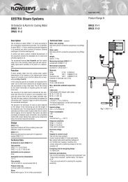
B<strong>Continuous</strong> <strong>Blowdown</strong> <strong>Valves</strong>Capacity ChartsChart 1: BA 46, BA 47, DN 15-32BAE 46, BAE 47, DN 15-32Differential pressure [bar]Chart 2: BA 46, BA 47, DN 40/50BAE 46, BAE 47, DN 40/50Differential pressure [bar]Hot-water capacity [kg/h]Hot-water capacity [kg/h]Position of control leverPosition of control leverChart 3: BA 210, BA 211BAE 210, BAE 211Chart 4: ZK 29ZKE 291 ) For relatively small quantities (dotted line in chart)use 210 k or 211 k (with special stage nozzle).Chart 5:BAE 210k, 211k