2. Encoder Signal Input Terminal - agenzia ing. pini
2. Encoder Signal Input Terminal - agenzia ing. pini
2. Encoder Signal Input Terminal - agenzia ing. pini

Create successful ePaper yourself
Turn your PDF publications into a flip-book with our unique Google optimized e-Paper software.
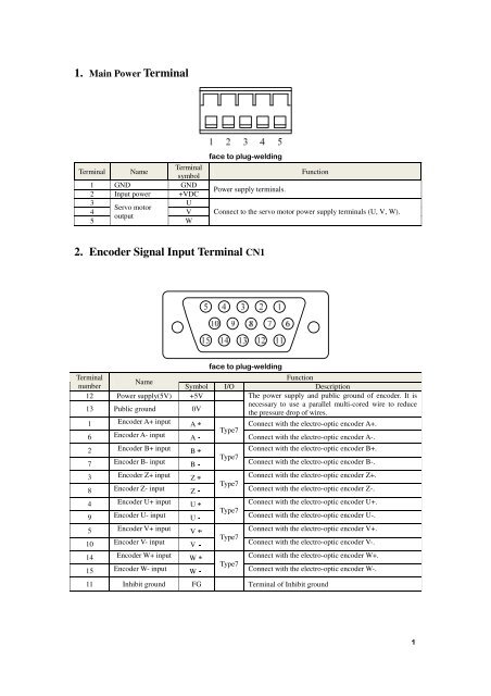
1. Main Power <strong>Terminal</strong><strong>Terminal</strong> Name<strong>Terminal</strong>symbol1 GND GND2 <strong>Input</strong> power +VDC3 UServo motor4 Voutput5W FunctionPower supply terminals.Connect to the servo motor power supply terminals (U, V, W).<strong>2.</strong> <strong>Encoder</strong> <strong>Signal</strong> <strong>Input</strong> <strong>Terminal</strong> CN1 <strong>Terminal</strong>FunctionNamenumberSymbol I/O Description12 Power supply(5V) +5VThe power supply and public ground of encoder. It is13 Public ground 0Vnecessary to use a parallel multi-cored wire to reducethe pressure drop of wires.1 <strong>Encoder</strong> A+ input A Connect with the electro-optic encoder A+.Type76 <strong>Encoder</strong> A- ¡input A Connect with the electro-optic encoder A-.2 <strong>Encoder</strong> B+ input B Connect with the electro-optic encoder B+.Type77 <strong>Encoder</strong> B- ¡input B Connect with the electro-optic encoder B-.3 <strong>Encoder</strong> Z+ input Z Connect with the electro-optic encoder Z+.Type78 <strong>Encoder</strong> Z- ¡input Z Connect with the electro-optic encoder Z-.4 <strong>Encoder</strong> U+ input U Connect with the electro-optic encoder U+.Type79 <strong>Encoder</strong> U- ¡input U Connect with the electro-optic encoder U-.5 <strong>Encoder</strong> V+ input V Connect with the electro-optic encoder V+.Type710 <strong>Encoder</strong> V- ¡input V Connect with the electro-optic encoder V-.14 <strong>Encoder</strong> W+ input W Connect with the electro-optic encoder W+.Type715 <strong>Encoder</strong> W- ¡input W Connect with the electro-optic encoder W-.11 Inhibit ground FG <strong>Terminal</strong> of Inhibit ground
¢3. Control <strong>Signal</strong> I/O <strong>Terminal</strong>s CN2<strong>Terminal</strong>numberName<strong>Terminal</strong> symbol Symbol I/O modeFunction20 ServoEn19ServoenableServoEn ¡Type1Servo enable input terminal.ServoEn ON: Operation enabled;ServoEn OFF: Operation disabled.[Note 1]: Make sure the servo motor is quiescentbefore “ServoEn OFF” turns to “ServoEn ON”[Note 2]: Please wait for 50 ms before inputt<strong>ing</strong>any command in the State of “ServoEn ON”.3 AlarmClrAlarm clear12¡ AlarmClrType1Alarm clear input terminal.AlarmClr ON: Clear the system alarm;AlarmClr OFF: Maintain the system alarm.[Note]: As the alarm code is less than 12, pleasecut off the power supply and repair the drive.5 AlarmServo alarmoutput14¡ AlarmType2Output terminal of servo alarm.ALM ON: Servo alarm output ON as there is noalarm;ALM OFF: Servo alarm output OFF as there isany alarm.¡2 Commandpulse PLUSPulseInv11 input PulseInv¡1 Commandpulse SIGNSignInv10 input SignInvType3Type3PPExternal command pulse input terminal.Note: pulse type is selected by parameter PN5<strong>2.</strong>PN52=0, command pulse+ signal mode(defaultstate);PN52=1, CCW/CW command pulse mode;PN52=2, 2-phase command pulse mode.2425Analogcommandinputspeed/torASPEED /ATORQUEASPEED ¡ /Type4S£ TCommand input terminal for external analogspeed and torque (difference mode), theimpedance is 10k, the voltage is -10V~+10V.