
You also want an ePaper? Increase the reach of your titles
YUMPU automatically turns print PDFs into web optimized ePapers that Google loves.
<strong>CABLES</strong> <strong>AND</strong><strong>WIRES</strong>Novi Sad, Republic of Serbia
Sale Centers<strong>Novkabel</strong> ADSerbia, 21000 Novi SadIndustrijska bbТel: +381 21 21 00 520Fax: +381 21 21 00 522e-mail: info@novkabel.comwww.novkabel.comWestern Europe Representative:DP Handel GmbHWestendstrasse 24D-60325 Frankfurt am Main, GermanyTel: + 44 69 97 14 810Fax: + 44 69 97 14 81 15e-mail: dp_handel_gmbh@t-online.deMoscow Representative:Российская Федерация, 123100 МоскваУл. Мантулинская, дом 5, стр. 3Тел: + 7 499 244 06 15/16Факс: + 7 499 244 08 03e-mail: info@eph.ru
ContentPOWER <strong>CABLES</strong>...............................................002POWER CONDUCTORS...............................034SIGNAL <strong>CABLES</strong>...............................................046RUBBER <strong>CABLES</strong>............................................058TELECOMUNICATION <strong>CABLES</strong>...............090ELECTRONIC <strong>CABLES</strong>...................................122AUDIO <strong>CABLES</strong>................................................134HALOGEN FREE <strong>CABLES</strong>............................142COAXIAL <strong>CABLES</strong>.........................................176OVERHEAD LINES......................................180METAL PRODUCTS........................................194TECHNICAL DATA...........................................208
POWER <strong>CABLES</strong>N(A)YY 003N(A)YCY 005N(A)YBY 007N(A)YRGY 009N(A)YFGY 011N(A)2XY 013N(A)2XBY 015N(A)2XRGY 017N(A)2XFGY 019N(A)YSY 021N(A)YSEY 022N(A)YSEYBY 023N(A)YSEYRGY 024N(A)YSEYFGY 025N(A)2XSY 026N(A)2XSEY 027N(A)2XS(F)2Y 028XHEh 91 029N(A)2XSYBY 030N(A)2XSYRGY 031N(A)2XSYFGY 032POWER CONDUC-TORSH07V-U, -R 035NYM 036PP-R 037PP-U 038H07V-K 039H03VH-H 040H03VV-F 041H05VV-F 042PP-JZ 043H05VVH6-F 044SIGNAL <strong>CABLES</strong>NYY 047NYBY 048NYRGY 049NYSY 050N2XY 051NYSLY 052NYSLYCY 053NYSLYÖ(H05VV5-F) 054NYSLYCYÖ(H05VVC4V5-F) 055SEZ 056SPZ 057RUBBER <strong>CABLES</strong>H01N2-E, -D 059H05RR-F 060H05RN-F 061NFK EpG 062NFK TES 063ZEpN, BT, HT 064NSGAFöu 065KPSRM 066PPSRVM 067PPSRMO 068NGFLGöu 069NFK SiSi/JU 070NSHTöu 071Si/F 072NFK SiSi/J 073NSSHöu 074NFK EpN 50 075H07RN-F 076NSSHöu.../3E 077NSSHöu...KON 078EpN 58 079NSSHCGEöu...+üI 080NSSHCGEöu.../3 081NSSHCGEöu...+St+ üI 082NSSHCGEöu.../ 083KON+St+üINTSCGECWöu... 084KONNTSCGECWöu... 085KONNTSCGERWöu... 086KONNTSCGEWöu.../3 087NTSCGEWöu.../ 0883E+St+ üIMGG,MGCG, 089FMGCGTELECOMUNICATION<strong>CABLES</strong>TK59 DSL 091TK59 DSL -120 0922YY 093J-YY 094J-Y(ST)Y 095JE-Y(ST)Y 096TI 20 097TM 20 098TC 44 099TI 44 100TZ 44 101TSV 102TK 33 U 103TK 39 M, GM 104TK 59 M, GM 105TK 59 TP 106TK 59 GMR 107TPP 108TPPEP 109A-02Y(L)2Y 110A-2Y(L)2Y 111A-2YF(L)2Y 112TD 59 UP 113TD 59M, GM 114TB-TZB 115TG-TZG 116S-YY 117S-Y(ST)Y 118TO SM 03 119TO SM 19 120ELECTRONIC <strong>CABLES</strong>Y 123YV 1246Y 1257Y 126LiY, LiY-T 127Li6Y 128Li7Y 129LiYY, So-LiYY 130LiYCY, So-LiYC Y 131LiYCY, So-LiYC Y 132AUDIO <strong>CABLES</strong>NAUK 001 135NAUK 100 136NAUK 102 137NAUK 200 138NAUK 300 139NAUK 900, 905 140NAUK 901, 904 141HALOGEN FREE<strong>CABLES</strong>LiHH 143LiHCH 144H05Z 145H07Z 146H07ZZ-F 147NHXMH 148N2XH 149N2XH FE 180 150N2XSH 151N2XS(E)H 152NHXHX 153NHXHX FE 180 154NHXCHX 155NHXCHX FE 180 156LiHXHX 157LiHXHX FE 180 158LiHXCHX 159LiHXCHX FE 180 160ILAN 120 (ohm) H 161J-02Y(St)H 162J-2Y(St)H 163TC 88 K (EK) 164TZ 88 E (GE) 166THI 167THM 168J-HH 169J-H(St)H 170JE-H(St)H FE 20 171JE-H(St)H FE 180 172MGH, MGCH, 173FMGCHNFK MGH, 174NFK MGCH,NFK FMGCHCOAXIAL <strong>CABLES</strong>RG 50 177RG 75 178OVERHEAD LINESAlumoveld 181ConductorsAlMgSi182ConductorsAluminium 183ConductorsAl/steel184ConductorsHard copper and 186bronze ropesProtective ropes 187for transmissionlinesPP/O 188X00-A 189X00/O-A 190СИП 3 191XHP 48/O-A; XHE 19249/O-AMETAL PRODUCTSWIRE OF195ALUMINIUMCOPPER WIRE 196TINNED COPPER 197WIREALUMINIUM 198CONDUCTORSCOPPER199CONDUCTORSBRAIDED COP- 201PER ROPESCONDUCTORS 202FOR MEASURINGTRANSFORMERSFLAT BRAIDS 203BRASS WIRE 204WIRE FOR 205EROSIMATETECHNICAL DATAProporties of 209materials usedfor cables productionHalogen-free 210flame retardantmaterialsConductor resistance213Core marking 215Nominal voltage 218CURRENT LOAD 219Transport reels 235Laying of Cables 238
Company ProfileAbout usThe Cable Factory based in Novi Sad wasestablished in 1921 and represents the oldestcable factory in the Balkans.We supply a wide range of energy cablesand conductors, telecommunication cablesand cables for electronic equipment to suitvarious industrial needs of constructionindustry, mining, shipbuilding, as well as oil,transportation, automotive industry and otherindustries.NOVKABEL, a member ofObjectiveNOVKABEL focuses on quality with utmost respect of the client’sneeds producing cables in accordance with the quality standards andecology requirements.Our goal is to remain the leading company in production anddistribution of all types of cables by improving the sales, conqueringnew markets, expanding the distribution network and strengtheningthe relations with business partners.Capacity<strong>Novkabel</strong> production plant occupies an area of almost 40 hectares inthe industrial zone of Novi Sad with the production capacity of up to35.000 tons per year.Research and developmentPoint Group is the leading regional group withsubsidiaries and associated companies thatoperate mainly in South East Europe. The corebusiness activities of the Point Group are: copperprocessing and trading, wholesale grain trading,mill and bakery industry, river transport, realestate and engineering. The major part of thebusiness activity has been conducted in Serbia,Romania, Hungary and Austria. Point Group alsohas its branch offices in the following leadingbusiness centers: Moscow, New York, Frankfurtand Beijing.From its modest beginnings in the product range, with the work ofgenerations of employees on the development of new products, thefactory has achieved about 16.000 registered products. NOVKABELexperts dedicate significant amounts of time to follow andimplement the latest technical and technological achievements incable production.QualityWe carry out all quality control procedures to ensure that all rawmaterials meet intake specifications and follow production until thedispatch of finished products; therefore, the investment into controlequipment is one of <strong>Novkabel</strong>’s priorities.NOVKABEL IS A RECOGNIZABLE PRODUCTIONBR<strong>AND</strong> IN CABLE INDUSTRY THROUGHOUTSOUTHEASTERN EUROPE, WITH THE POSITIONOF THE LEADING PROVIDER REGARDING THEQUALITY <strong>AND</strong> RANGE OF PRODUCTS.
POWER <strong>CABLES</strong>N(A)YY 003 N(A)YSEY 022N(A)YCY 005 N(A)YSEYBY 023N(A)YBY 007 N(A)YSEYRGY 024N(A)YRGY 009 N(A)YSEYFGY 025N(A)YFGY 011 N(A)2XSY 026N(A)2XY 013 N(A)2XSEY 027N(A)2XBY 015 N(A)2XS(F)2Y 028N(A)2XRGY 017 XHEh 91 029N(A)2XFGY 019 N(A)2XSYBY 030N(A)YSY 021 N(A)2XSYRGY 031N(A)2XSYFGY 032
[Type text]PP 00, PP 00-AВВГ, АВВГ; NYY, NAYYPower cables with PVC insulation and sheathStandard: SRPS N.C5.220Nominal voltage U 0 /U: 0,6/1 kVTest voltage:3,5 kVCONSTRUCTIONConductor: wire or rope, class 1 or 2, according to SRPSN.C0.015, copper: type PP 00, or aluminium: type PP 00-A.Insulation: PVC compound.Core: two or multi cores are stranded together.Fillig: non hygroscopic, non vulcanized rubber compound layeror thermoplastic compound layer. Cables with sector shapedconductors (designated S in table) wrapped thermoplastic tapes.Sheath: PVC compound.Sheat colour black.APPLICATIONFor laying indoors, in ducts, in earth, in the open air, in urbannetworks and industrial plants, electric power plants andswitchgear assemblies, where one cannot expect mechanicaldamages.CONSTRUCTION DATACu number Al numberDiameterMass [kg/km]Construction 1) PP00 PP00-A[kg/km] [kg/km] [mm] PP00 PP00-A1x1,5 14,4 - 7,0 65 -1x2,5 24 - 7,5 82 -1x4 38 12 8,0 105 781x6 58 18 8,5 125 891x10 96 29 9,5 174 1101x16 154 46 11,0 252 1431x25 240 72 13,0 363 2041x35 336 102 13,5 475 2511x50 480 145 15,5 637 3161x70 672 203 17,5 850 3981x95 912 276 19,0 1115 5161x120 1152 348 20,5 1365 6171x150 1440 435 22,5 1707 7361x185 1778 537 24,5 2056 8961x240 2304 696 28,0 2657 11312x1,5 29 - 10,5 150 -2x2,5 48 - 11,5 197 -2x4 77 23 13,0 270 2352x6 115 36 14,5 365 2772x10 192 58 16,5 494 3502x16 307 93 19,0 683 4672x25 480 145 22,0 1005 6883x1,5 43 - 11,0 171 -3x2,5 72 - 12,0 227 -003
Cu number Al numberDiameterMass [kg/km]Construction 1) PP00 PP00-A[kg/km] [kg/km] [mm] PP00 PP00-A0043x4 115 35 14,0 307 2843x6 173 52 15,0 400 3063x10 288 87 17,0 570 3913x16 461 139 20,5 851 5303x25 * 720 218 23,0 1246 7363x35 * 1008 305 27,0 1686 930S 3x50 1440 435 25,0 1715 853S 3x70 2016 609 28,5 2391 1095S 3x95 2736 827 32,5 3251 1438S 3x120 3456 1044 35,5 4037 1742S 3x150 4320 1305 39,5 4928 2128S 3x185 5328 1610 43,5 6127 2597S 3x240 6912 2088 49,0 7983 33633x25+16 * 874 263 24,5 1278 8503x35+16 * 1162 351 27,0 1627 1109S 3x50+25 1680 507 29,0 2105 1019S 3x70+35 2352 711 30,0 2760 1340S 3x95+50 3216 972 34,5 3794 1715S 3x120+70 4128 1247 38,0 4755 2019S 3x150+70 4992 1508 41,0 5645 2433S 3x185+95 6240 1888 48,5 7361 3046S 3x240 +120 8064 2436 54,0 9492 39034x1,5 58 - 12,0 201 -4x2,5 96 - 13,0 270 -4x4 154 46 15,0 378 2984x6 230 70 16,5 483 3544x10 384 116 18,5 692 4564x16 614 186 22,0 1044 5914x25 960 290 25,5 1542 9094x35 1344 406 28,5 2011 1210S 4x50 1920 580 29,5 2380 1103S 4x70 2688 812 33,0 3144 1356S 4x95 3648 1102 38,5 4381 1883S 4x120 4608 1392 41,5 5310 2248S 4x150 5760 1740 46,0 6569 2737S 4x185 7104 2148 51,0 8127 3430S 4x240 9216 3480 58,0 10560 44045x1,5 72 - 12,5 238 -5x2,5 120 - 14,0 323 -5x4 192 58 16,5 455 3525x6 288 88 17,5 582 4215x10 480 145 20,5 838 5465x16 768 233 24,0 1275 7295x25 1200 363 28,5 1925 1226* It is possible to produce construction sector shape according to customer requirement.1)S in front of the wire number means sector shape conductor.Permissible conductor temperature:- operating temperature, max +70°C,- in short circuit (max 5 s), max +160°C.Permissible environment temperature:- at laying and handling, min +5°C.Smallest bending radius: single core cables 15D; multi core cables 12D (D – cable diameter).
PP 40, PP 40-AВВГЭ, АВВГЭ; NYCY, NAYCYPower cables with electrical protectionStandard: SRPS N.C5.220Nominal voltage U 0 /U: 0,6/1 kVTest voltage:3,5 kVCONSTRUCTIONConductor: wire or rope, class 1 or 2, according to SRPSN.C0.015, copper: type PP 40, or aluminium: type PP 40-A.Insulation: PVC compound.Core: two or multi cores are stranded together.Fillig: non hygroscopic, non vulcanized rubber compound layeror thermoplastic compound layer.Concentric conductor: wrapped annealed copper wires withcontra-helical annealed copper tape or wrapped copper tape.Sheath: PVC compound.Sheat colour black.APPLICATIONFor laying in earth, indoors, in duckt, in open air in urbannetworks, for connection of home devices and public illuminations,industrial plants and electric power plants where cables expectedto provide electrical protection. Concentric conductor could beused as neutral or protective conductor.CONSTRUCTION DATACu number Cu number Al numberDiameterMass [kg/km]Construction 1) PP40 PP40-A PP00-A[kg/km] [kg/km] [kg/km] [mm] PP40 PP40-A0052x4/4 123 27 23 16,0 363 2892x6/6 182 44 36 17,0 428 3492x10/10 312 64 58 19,0 593 4422x16/16 489 100 93 22,0 866 5712x25/25 763 162 145 26,0 1310 8763x4/4 161 27 35 16,5 410 3163x6/6 240 44 52 18,0 518 3833x10/10 408 62 87 20,0 718 4833x16/16 643 102 139 23,0 1036 6353x25 * /16 902 102 218 27,5 1443 9113x35 * /16 1190 102 305 29,0 1930 1080S 3x50/25 1723 157 435 29,0 2065 1062S 3x70/35 2410 208 609 31,5 2800 1360S 3x95/50 3296 288 827 37,0 3823 1825S 3x120/70 4236 384 1044 40,0 4823 2196
Cu number Cu number Al numberDiameterMass [kg/km]Construction 1) PP40 PP40-A PP00-A[kg/km] [kg/km] [kg/km] [mm] PP40 PP40-AS 3x150/70 5100 420 1305 42,5 5602 2612S 3x185/95 6383 563 1610 48,0 7290 3303S 3x240/ 120 8242 773 2088 53,5 9085 41903x25/25 * 1003 162 216 27,0 1550 9733x35/35 1402 208 305 29,5 2100 1187S 3x50/50 2000 288 435 29,0 2350 1194S 3x70/75 2796 399 609 32,5 3190 1550S 3x95/95 3791 554 827 37,5 4300 2088S 3x120/120 4786 721 1044 40,5 5300 2528S 3x150/150 5970 818 1305 43,5 6450 3008S 3x185/185 7363 1069 1610 49,0 7939 37984x4/4 200 27 46 18,0 480 3574x6/6 297 47 70 19,0 590 4344x10/10 504 62 116 21,0 856 5524x16//16 796 102 186 23,5 1192 7284x25 * /16 1142 102 290 30,0 1802 10524x35 * /16 1526 102 406 31,5 2175 1258S 4x50/25 2203 157 580 33,0 2640 1295S 4x70/35 3082 208 812 35,0 3574 1699S 4x95/50 4208 289 1102 40,5 4834 2229S 4x120/70 5388 420 1392 44,5 5938 2717S 4x150/70 6540 420 1740 48,0 7296 3318S 4x185/95 8044 593 2148 53,5 9133 4086S 4x240/ 120 10330 773 2784 61,0 11865 5296* It is possible to produce construction sector shape according to customer requirement.1)S in front of the wire number means sector shape conductor.006Permissible conductor temperature:- operating temperature, max +70°C,- in short circuit (max 5 s), max +160°C.Permissible environment temperature:- at laying and handling, min +5°C.Smallest bending radius: 12D (D – cable diameter).
PP 44; PP 44-ANYRGY, NAYRGYPower cables with mechanical protectionStandard: SRPS N.C5.220Nominal voltage U 0 /U: 0,6/1 kVTest voltage:3,5 kVCONSTRUCTIONConductor: wire or rope, class 1 or 2, according to SRPSN.C0.015, copper: type PP 44, or aluminium: type PP 44-A.Insulation: PVC compound.Core: two or multi cores are stranded together.Filling: non hygroscopic, non vulcanized rubber compound layeror thermoplastic compound layer.Armour: wrapped zinc-plated round steel wire with or withoutcontra helical zinc-plated steel tape (obligatory when cable isused in mines).Sheath: PVC compound.Sheat colour black.APPLICATIONFor laynig in earth, indoors, in ducts, in the open air, in the water,when additional mechanical protection is required when cable isexposed to mechanical tensile strain during laying and use. Foruse in mines according to Technical standards for electrical plants,equipments and installations in mines, as well as horizontal andvertical installation in places where there is a height difference inmines, including methane holes.CONSTRUCTION DATA009Cu number Al numberDiameterMass [kg/km]Construction 1) PP44 PP44-A[kg/km] [kg/km] [mm] PP44 PP44-A3x6 183 52 18,5 775 5603x10 288 67 21,0 1034 6803x16 461 139 24,0 1408 11203x25 * 720 218 28,0 1871 14703x35 * 1008 305 30,0 2204 1980S 3x50 1440 435 31,0 2760 1870S 3x70 2016 609 35,0 3760 2470S 3x95 2736 827 39,0 4519 3020S 3x120 3456 1044 42,0 5710 3420S 3x150 4320 1305 47,0 7240 4440S 3x185 5328 1610 52,0 8700 5170S 3x240 6912 2088 58,0 10950 6270
Cu number Al numberDiameterMass [kg/km]Construction 1) PP44 PP44-A[kg/km] [kg/km] [mm] PP44 PP44-A3x25+16 * 874 263 29,0 2100 15203x35+16 * 1162 351 31,0 2482 1760S 3x50+25 1680 507 35,0 3550 2490S 3x70+35 2352 711 36,5 4062 2940S 3x95+50 3216 972 41,0 5184 2950S 3x120+70 4128 1247 43,5 6222 4650S 3X150+70 4992 1508 53,0 8580 5350S 3X185+95 6240 1886 53,5 9308 6100S 3X240+120 8064 2436 64,0 12636 72094x6 230 70 20,0 758 6404x10 384 116 21,5 973 7804x16 614 186 26,5 1576 12704x25 * 960 290 31,0 2251 16284x35 * 1344 406 36,0 3440 2540S 4x50 1920 580 34,5 3349 2510S 4x70 2688 812 38,5 4320 2580S 4x95 3648 1102 43,0 5637 3680S 4x120 4608 1392 47,0 7137 4730S 4x150 5760 1740 51,5 8566 4827S 4x185 7104 2148 56,5 10345 6250S 4x240 9216 2784 64,0 13642 77705x6 288 88 22,0 1040 7255x10 480 145 25,0 1276 12005x16 768 - 30,0 2190 -5x25 1200 - 33,0 2547 -* It is possible to produce construction sector shape according to customer requirement.0101)S in front of the wire number means sector shape conductor.Permissible conductor temperature:- operating temperature, max +70°C,- in short circuit (max 5 s), max +160°C.Permissible environment temperature:- at laying and handling, min +5°C.Smallest bending radius: 12D (D – cable diameter).
XP 00, XP 00-AN2XY, NA2XYPower cables with XLPE insulationStandard: SRPS N.C5.230Nominal voltage U 0 /U: 0,6/1 kVTest voltage:3,5 kVCONSTRUCTIONConductor: wire or rope, class 1 or 2, according to SRPSN.C0.015, copper: type XP 00, or aluminium: type XP 00-A.Insulation: XLPE compound.Core: two or multi cores are stranded together.Filling: non hygroscopic, non vulcanized rubber compound layeror thermoplastic compound layer. Cables with sector shapedconductors (designated S in the table) wrapped thermoplastictapes.Sheath: PVC compound.Sheath colour black.APPLICATIONFor laying indoors, in ducts, in earth, in the open air, in urbannetworks and industrial plants, electric power plants andswitchgear assemblies, where one cannot expect mechanicaldamages.CONSTUCTION DATACu number Al numberDiameterMass [kg/km]Construction 1) XP00 XP00-A[kg/km] [kg/km] [mm] XP00 XP00-A1x1,5 14,4 - 6,5 46 -1x2,5 24 - 7,0 59 -1x4 38 12 7,5 77 521x6 58 18 8,5 109 631x10 96 29 9,5 169 901x16 154 46 10,5 221 1161x25 240 72 12,0 324 1711x35 336 102 13,0 425 2081x50 480 145 14,5 579 2661x70 672 203 17,0 788 3441x95 912 276 18,5 1044 4371x120 1152 348 19,5 1277 5331x150 1440 435 22,0 1605 6421x185 1778 537 24,0 1938 7851x240 2304 696 27,0 2501 10092x1,5 29 - 10,0 129 -2x2,5 48 - 10,5 164 -2x4 77 23 12,0 218 1682x6 115 36 13,5 291 2462x10 192 58 15,5 420 2962x16 307 93 17,5 586 3882x25 480 145 21,0 886 5713x1,5 43 - 10,5 148 -3x2,5 72 - 12,0 202 -013
Cu number Al numberDiameterMass [kg/km]Construction 1) XP00 XP00-A[kg/km] [kg/km] [mm] XP00 XP00-A0143x4 115 35 12,5 258 1843x6 173 52 13,5 333 2363x10 288 87 15,5 490 3293x16 461 139 18,5 731 4333x25 * 720 218 22,0 1099 6393x35 * 1008 305 24,5 1445 794S 3x50 1440 435 23,5 1579 679S 3x70 2016 609 27,5 2223 933S 3x95 2736 827 30,5 3000 1195S 3x120 3456 1044 33,5 3750 1463S 3x150 4320 1305 37,5 4623 1834S 3x185 5328 1610 41,5 5747 2229S 3x240 6912 2088 47,5 7557 28973x25+16 * 874 263 23,0 1268 6923x35+16 * 1162 351 26,0 1619 864S 3x50+25 1680 507 27,5 1963 807S 3x70+35 2352 711 30,5 2621 1143S 3x95+50 3216 972 34,5 3511 1443S 3x120+70 4128 1247 38,5 4482 1813S 3x150+70 4992 1508 44,0 5564 2078S 3x185+95 6240 1888 49,5 7093 2844S 3x240 +120 8064 2436 53,0 8947 35284x1,5 58 - 11,0 172 -4x2,5 96 - 12,0 226 -4x4 154 46 13,5 301 2104x6 230 70 14,5 404 3134x10 384 116 16,5 577 3834x16 614 186 20,0 853 4974x25 * 960 290 24,0 1331 7524x35 * 1344 406 26,0 1770 966S 4x50 1920 580 27,0 2146 886S 4x70 2688 812 31,5 2977 1214S 4x95 3648 1102 35,5 3947 1566S 4x120 4608 1392 39,5 4976 1915S 4x150 5760 1740 43,5 6178 2329S 4x185 7104 2148 49,0 7666 3236S 4x240 9216 3480 54,5 9829 43695x1,5 72 - 12,0 203 -5x2,5 120 - 13,0 269 -5x4 192 58 14,5 360 2405x6 288 88 16,5 488 3245x10 480 145 18,0 701 4575x16 768 233 21,5 1087 5835x25 1200 363 27,0 1726 953Permissible conductor temperature:- operating temperature, max +90°C,- in short circuit (max 5 s), max +250°C.Permissible environment temperature:- at laying and handling, min +5°C.Smallest bending radius: - single core cables 15D; - multi core cables 12D (D – cable diameter).
XP 41, XP 41-AПвБбШв, АПвБбШвN2XBY, NA2XBYPower cables with XLPE insulation and mechanical protectionStandard: SRPS N.C5.230Nominal voltage U 0 /U: 0,6/1 kVTest voltage:3,5 kVCONSTRUCTIONConductor: wire or rope, class 1 or 2, according to SRPSN.C0.015, copper: type XP 41, or aluminium: type XP 41-A.Insulation: XLPE compound.Core: two or multi cores are stranded together.Filling: non hygroscopic, non vulcanized rubber compound layeror thermoplastic compound layer.Armour: wrapped two steel tapes.Sheath: PVC compound.Sheath colour black.APPLICATIONFor laying in earth, indoors, in ducts, in the open air in urbannetworks, industrial plants and electric power plants, whenmechanical damage could be expected, due to rodents and handtools. Laying on sloping grounds is not allowed, nor cable hanging.CONSTRUCTION DATACu number Al numberDiameterMass [kg/km]Construction 1) XP41 XP41-A[kg/km] [kg/km] [mm] XP41 XP41-A0152x1,5 29 - 14,5 387 -2x2,5 48 - 15,0 441 -2x4 77 23 16,0 512 4622x6 115 36 17,0 596 5212x10 192 58 19,0 748 6232x16 307 93 21,5 997 7542x25 480 145 24,5 1256 10513x1,5 43 - 15,0 416 -3x2,5 72 - 15,5 479 -3x4 115 35 16,0 473 4893x6 173 52 18,0 672 5603x10 288 87 19,0 754 6633x16 461 139 22,5 1165 8183x25 * 720 218 26,0 1631 11673x35 * 1008 305 28,5 2034 1382S 3x50 1440 435 28,0 2118 1218
Cu number Al numberDiameterMass [kg/km]Construction 1) XP41 XP41-A[kg/km] [kg/km] [mm] XP41 XP41-A016S 3x70 2016 609 31,5 2826 1530S 3x95 2736 827 34,5 3672 1859S 3x120 3456 1044 38,0 4519 2224S 3x150 4320 1305 41,5 5445 2646S 3x185 5328 1610 46,5 6739 3209S 3x240 6912 2088 51,0 8560 38143x25+16 * 874 263 27,5 1818 12423x35+16 * 1162 351 29,5 2207 1444S 3x50+25 1680 507 30,5 2487 1426S 3x70+35 2352 711 34,5 3313 1796S 3x95+50 3216 972 40,0 4580 2213S 3x120+70 4128 1247 44,0 5649 2625S 3x150+70 4992 1508 46,5 6641 3196S 3x185+95 6240 1888 53,5 8237 3787S 3x240 +120 8064 2436 57,5 10185 45224x1,5 58 - 15,5 458 -4x2,5 96 - 16,5 536 -4x4 154 46 17,5 639 5394x6 230 70 19,0 765 6164x10 384 116 20,5 888 7524x16 614 186 23,5 1231 8304x25 * 960 290 26,5 1613 9724x35 * 1344 406 31,0 2450 1563S 4x50 1920 580 30,5 2665 1465S 4x70 2688 812 34,0 3596 1869S 4x95 3648 1102 38,5 4623 2255S 4x120 4608 1392 42,0 5749 2726S 4x150 5760 1740 46,0 7001 3263S 4x185 7104 2148 51,5 8493 3882S 4x240 9216 3480 57,5 10818 49645x1,5 72 - 16,0 425 -5x2,5 120 - 17,5 602 -5x4 192 58 18,5 621 6005x6 288 88 20,0 769 6925x10 480 145 22,0 1050 8605x16 768 233 26,0 1495 10985x25 1200 363 30,0 2139 1567* It is possible to produce construction sector shape according to customer requirement.1)S in front of the wire number means sector shape conductor.Permissible conductor temperature:- operating temperature, max +90°C,- in short circuit (max 5 s), max +250°C.Permissible environment temperature:- at laying and handling, min +5°C.Smallest bending radius: 12D (D – cable diameter).
XP 44; XP 44-AN2XRGY, NA2XRGYPower cables with mechanical protectionStandard: SRPS N.C5.230Nominal voltage U 0 /U: 0,6/1 kVTest voltage:3,5 kVCONSTRUCTIONConductor: wire or rope, class 1 or 2, according to SRPSN.C0.015, copper: type XP 44, or aluminium: type XP 44-A.Insulation: XLPE compound.Core: two or multi cores are stranded together.Filling: non hygroscopic, non vulcanized rubber compound layeror thermoplastic compound layer.Armour: wrapped zinc-plated round steel wire with or withoutcontra helical zinc plated steel tape (obligatory when cable isused in mines).Sheath: PVC compound.Sheath colour black.APPLICATIONFor laying in earth, indoors, in ducts, in the open air, in the water,when additional mechanical protection is required when cable isexposed to mechanical tensile strain during laying and use. For usein mines according to Technical standards for electrical plants,equipments and installations in mines, as well as horizontal andvertical installation in places where there is a height difference inmines, including methane holes.CONSTRUCTION DATA017Cu number Al numberDiameterMass [kg/km]Construction 1) XP44 XP44-A[kg/km] [kg/km] [mm] XP44 XP44-A3x6 183 52 17,0 612 5003x10 288 67 19,0 800 6113x16 461 139 22,5 1242 7513x25 * 720 218 27,0 1872 14003x35 * 1008 305 30,0 2290 1651S 3x50 1440 435 30,0 2507 1607S 3x70 2016 609 34,0 3384 2187S 3x95 2736 827 37,5 4420 2608S 3x120 3456 1044 40,5 5298 3000S 3x150 4320 1305 44,0 6298 3500S 3x185 5328 1610 50,0 8103 4573S 3x240 6912 2088 55,0 10057 5380
Cu number Al numberDiameterMass [kg/km]Construction 1) XP44 XP44-A[kg/km] [kg/km] [mm] XP44 XP44-A3x25+16 * 874 263 28,0 1933 14973x35+16 * 1162 351 29,5 2284 1720S 3x50+25 1680 507 32,5 2897 1838S 3x70+35 2352 711 37,5 4060 2543S 3x95+50 3216 972 41,0 5122 3011S 3x120+70 4128 1247 44,0 6206 3478S 3X150+70 4992 1508 50,5 7787 4540S 3X185+95 6240 1886 54,5 9419 5286S 3X240+120 8064 2436 61,5 11882 64444x6 230 70 14,5 701 5574x10 384 116 16,5 929 6854x16 614 186 24,5 1472 11404x25 * 960 290 28,5 2037 15934x35 * 1344 406 30,0 2490 1876S 4x50 1920 580 34,0 3574 1879S 4x70 2688 812 37,5 4345 2608S 4x95 3648 1102 41,0 5813 3101S 4x120 4608 1392 44,0 6661 3585S 4x150 5760 1740 50,0 8411 4715S 4x185 7104 2148 54,5 10202 5471S 4x240 9216 2784 62,0 12952 66865x6 288 88 19,5 822 8865x10 480 145 21,5 1087 10705x16 768 - 27,0 1911 13335x25 1200 - 31,5 2639 1858* It is possible to produce construction sector shape according to customer requirement.0181)S in front of the wire number means sector shape conductor.Permissible conductor temperature:- operating temperature, max +90°C,- in short circuit (max 5 s), max +250°C.Permissible environment temperature:- at laying and handling, min +5°C.Smallest bending radius: 12D (D – cable diameter).
XP 45, XP 45-AN2XFGY, NA2XFGYPower cables with mechanical protectionStandard: SRPS N.C5.230Nominal voltage U 0 /U: 0,6/1 kVTest voltage:3,5 kVCONSTRUCTIONConductor: wire or rope, class 1 or 2, according to SRPSN.C0.015, copper: type XP 45, or aluminium: type XP 45-A.Insulation: XLPE compound.Core: two or multi cores are stranded together.Filling: non hygroscopic, non vulcanized rubber compound layeror thermoplastic compound layer.Armour: wrapped zinc-plated flat steel wire with contra helicalzinc-plated steel tape.Sheath: PVC compound.Sheath colour black.APPLICATIONFor laying in earth, indoors, in ducts, in the open air, in the water,when additional mechanical protection is required when cable isexposed to mechanical tensile strain during laying and use. For usein mines according to Technical standards for electrical plants,equipments and installations in mines, as well as horizontal andvertical installation in places where there is a height difference inmines, including methane holes.CONSTRUCTION DATA019Cu number Al numberDiameterMass [kg/km]Construction 1) XP45 XP45-A[kg/km] [kg/km] [mm] XP45 XP45-A3x25 * 720 218 25,5 1617 11493x35 * 1008 305 28,0 2010 1354S 3x50 1440 435 28,0 2210 1309S 3x70 2016 609 31,5 2925 1628S 3x95 2736 827 35,0 3835 2023S 3x120 3456 1044 38,0 4662 2367S 3x150 4320 1305 42,0 5586 2787S 3x185 5328 1610 46,5 6900 3372S 3x240 6912 2088 51,5 8732 40573x25+16 * 874 263 26,5 1807 12303x35+16 * 1162 351 29,0 2193 1426S 3x50+25 1680 507 31,0 2593 1534S 3x70+35 2352 711 35,5 3476 1958S 3x95+50 3216 972 38,5 4461 2350
Cu number Al numberDiameterMass [kg/km]Construction 1) XP45 XP45-A[kg/km] [kg/km] [mm] XP45 XP45-AS 3x120+70 4128 1247 42,0 5494 2766S 3X150+70 4992 1508 47,0 6586 3339S 3X185+95 6240 1886 51,0 8095 3962S 3X240+120 8064 2436 58,0 10400 49644x6 230 70 18,0 753 6034x10 384 116 20,0 1006 7554x16 614 186 23,5 1374 9104x25 * 960 290 28,0 1946 13194x35 * 1344 406 30,5 2447 1572S 4x50 1920 580 31,0 2780 1574S 4x70 2688 812 35,0 3729 1992S 4x95 3648 1102 38,5 4870 2440S 4x120 4608 1392 41,5 5949 2873S 4x150 5760 1740 47,0 7264 3513S 4x185 7104 2148 51,0 8878 4147S 4x240 9216 2784 58,0 11436 51705x6 288 88 19,5 837 6865x10 480 145 21,5 1170 8575x16 768 233 25,5 1628 10575x25 1200 363 30,0 2325 1570* It is possible to produce construction sector shape according to customer requirement.1)S in front of the wire number means sector shape conductor.Permissible conductor temperature:- operating temperature, max +90°C,- in short circuit (max 5 s), max +250°C.020Permissible environment temperature:- at laying and handling, min +5°C.Smallest bending radius: 12D (D – cable diameter).
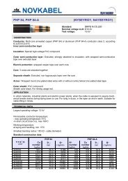
PHP 48, PHP 48-AВВГЭ, АВВГЭ, NYSY, NAYSYMedium voltage cables with PVC insulationStandard: SRPS N.C5.220Nominal voltage U 0 /U: 6/10 kVTest voltage:15 kVCONSTRUCTIONConductor: multi-core copper (PHP 48) or aluminium (PHP 48-A)conductor class 2, according to SRPS N.C0.015.Inner semi-conductive layerInsulation: special high-voltage PVC compound.Outer semi-conductive layer: extruded, with wrapped semiconductivetape over extruded layer.Electric protection: wrapped annealed copper wires with contrahelicalannealed copper tape or wrapped copper tape.Sheath: PVC compound.Sheath colour black, for use in mine red.APPLICATIONSuitable for laying down in closely rooms, for power plants,transformers, industrial plants, etc. Suitable for laying down intolessaccessible localities, because of its little weight.CONSTRUCTION DATAnxq/q 1[mm 2 ]Cu number[kg/km]PHP 48 PHP 48-ADiameter[mm]Mass[kg/km]Al number[kg/km]Cu number[kg/km]Diameter[mm]Mass[kg/km]1x25/16 360 23,0 896 72 182 23,0 7421x35/16 456 24,0 1023 102 182 24,5 8081x50/16 622 26,0 1204 145 182 26,0 9131x70/16 854 27,5 1456 203 182 27,5 10310211x95/16 1094 29,5 1764 276 182 29,5 11761x120/16 1334 31,0 2039 348 182 29,5 10561x150/25 1723 32,0 2448 435 283 31,0 12261x185/25 2059 34,0 2833 537 283 32,5 13711x240/25 2587 36,0 3324 696 283 37,0 19661x300/25 3163 38,5 3990 870 283 39,5 2225n – number of the wires, q – nominal cross section of the conductor, q 1 – cross section of the electricalprotectionPermissible conductor temperature:- operating temperature (constant load), max +70°C,- in short circuit (max 5 s), max +160°C.Permissible environment temperature:- at laying and handling, min +5°C.Smallest bending radius: 15D (D – cable diameter).
PHP 48, PHP 48-AВВГЭ, АВВГЭ, NYSEY, NAYSEYMedium voltage cables with PVC insulationStandard: SRPS N.C5.230Nominal voltage U 0 /U: 6/10 kVTest voltage:15 kVCONSTRUCTIONConductor: multi-core copper (PHP 48) or aluminium (PHP 48-A)conductor class 2, according to SRPS N.C0.015.Inner semi-conductive layerInsulation: special high-voltage PVC compound.Outer semi-conductive layer: extruded, with wrapped semiconductivetape over extruded layer.Electric protection: wrapped annealed copper wires with contrahelicalannealed copper tape or wrapped copper tape.Core: 3 cores are stranded together.Filling: extruded, non hygroscopic layer over the core thatcompletely fills the space between the cores.Outer sheath: PVC compound.Sheath colour black, for use in mine red.APPLICATIONIndoors, in ducts, in earth, in the open air in distributive lattice,industrial plants and power plants. Laying down, directly into theearth, is restricted by mechanical properties of PVC sheath.CONSTRUCTION DATA022nxq/q 1[mm 2 ]Cu number[kg/km]PHP 48 PHP 48-ADiameter[mm]Mass[kg/km]Al number[kg/km]Cu number[kg/km]Diameter[mm]Mass[kg/km]3x25/16 921 42,5 2769 218 231 42,5 23033x35/16 1209 47,5 3764 305 231 48,0 31233x50/16 1671 48,5 3909 435 231 48,5 29643x70/16 2247 54,0 4737 609 231 54,0 33893x95/16 2994 57,0 5747 827 258 56,0 40373x120/16 3714 58,0 6958 1044 258 61,0 44953x150/25 4603 63,0 8240 1305 315 65,0 52503x185/25 5611 66,5 9405 1610 315 66,5 58903x240/25 7272 75,5 12259 2088 362 76,0 76893x300/25 9160 78,5 13478 2610 520 78,5 7842n – number of the wires, q – nominal cross section of the conductor, q 1 – cross section of the electricalprotectionPermissible conductor temperature:- operating temperature, max +70°C,- in short circuit (max 5 s), max +160°C.Permissible environment temperature:- at laying and handling, min +5°C.Smallest bending radius: 15D (D – cable diameter).
PHP 81, PHP 81-ANYSEYBY, NAYSEYBYMedium voltage cables with PVC insulationStandard: SRPS N.C5.220Nominal voltage U 0 /U: 6/10 kVTest voltage:15 kVCONSTRUCTIONConductor: multi-core copper (PHP 81) or aluminium (PHP 81-A)conductor class 2, according to SRPS N.C0.015.Inner semi-conductive layerInsulation: special high-voltage PVC compound.Outer semi-conductive layer: extruded, with wrapped semiconductivetape over extruded layer.Electric protection: wrapped annealed copper wires with contrahelicalannealed copper tape or wrapped copper tape.Core: 3 cores are stranded together.Separate sheath: extruded, non hygroscopic layer over the corethat completely fills the space between the cores.Armour: wrapped two steel tapes.Sheath: PVC compound.Sheath colour black, for use in mine red.APPLICATIONIn urban networks, industrial plants and electric power plants, whenthe cable is exposed to mechanical damages. Indoors, in the openair, in ducts, in earth when mechanical protection is required.CONSTRUCTION DATAnxq/q 1[mm 2 ]Cu number[kg/km]PHP 81 PHP 81-ADiameter[mm]Mass[kg/km]Al number[kg/km]Cu number[kg/km]Diameter[mm]Mass[kg/km]3x25/16 921 46,0 3715 218 231 46,0 32613x35/16 1209 50,0 4377 305 231 50,0 37400233x50/16 1671 50,5 4754 435 231 52,5 41343x70/16 2247 56,0 5756 609 231 56,0 47173x95/16 2994 59,0 6932 827 258 59,0 51293x120/16 3714 64,0 8391 1044 258 62,0 56813x150/25 4603 67.5 9627 1305 315 68,0 68653x185/25 5611 72,0 11216 1610 315 73,0 78413x240/25 7272 77,5 13572 2088 362 78,0 90103x300/25 9160 82,5 15783 2610 520 84,0 10375n – number of the wire, q – nominal cross section of the conductor, q 1 – cross section of the electricalprotectionPermissible conductor temperature:- operating temperature (constant load), max +70°C,- in short circuit (max 5 s), max +160°C.Permissible environment temperature:- at laying and handling, min +5°C.Smallest bending radius: 15D (D – cable diameter).
PHP 84, PHP 84-ANYSEYRGY, NAYSEYRGYMedium voltage cables with PVC insulationStandard: SRPS N.C5.220Nominal voltage U 0 /U: 6/10 kVTest voltage:15 kVCONSTRUCTIONConductor: multi-core annealed copper (PHP 84) or aluminium(PHP 84-A) conductor class 2, according to SRPS N.C0.015.Inner semi-conductive layerInsulation: special high-voltage PVC compound.Outer semi-conductive layer: extruded, with wrapped semiconductivetape over extruded layer.Electric protection: wrapped annealed copper wires with contrahelicalannealed copper tape or wrapped copper tape.Core: 3 cores are stranded together.Separate sheath: extruded, non hygroscopic layer.Armour: wrapped round zinc-plated steel wires with or withoutcontra helical zinc-plated steel tape.Outer sheath: PVC compound.Sheath colour black, for use in mining red.APPLICATIONIn urban networks, industrial plants and electric power plants, whenthe cable is exposed to severe mechanical tensile strains duringlaying down or use. For laying in ducts, in the open air and in earth.Suitable for cable lifting in mines.CONSTRUCTION DATA024nxq/q 1[mm 2 ]Cu number[kg/km]PHP 84 PHP 84-ADiameter[mm]Mass[kg/km]Al number[kg/km]Cu number[kg/km]Diameter[mm]Mass[kg/km]3x25/16 921 50,5 5199 218 231 51,0 47433x35/16 1209 53,5 5854 305 231 53,5 52123x50/16 1671 55,0 5935 435 231 54,0 50203x70/16 2247 60,5 7772 609 231 60,5 64973x95/16 2994 62,5 8717 827 258 65,0 74003x120/16 3714 68,0 10281 1044 258 66,5 73513x150/25 4603 72,0 11767 1305 315 72,5 90343x185/25 5611 75,5 13330 1610 315 76,5 99793x240/25 7272 83,5 16961 2088 362 51,0 4743n – number of the wire, q – nominal cross section of the conductor, q 1 – cross section of the electricalprotectionPermissible conductor temperature:- operating temperature (constant load), max +70°C,- in short circuit (max 5 s), max +160°C.Permissible environment temperature:- at laying and handling, min +5°C.Smallest bending radius: 15D (D – cable diameter).
PHP 85, PHP 85-ANYSEYFGY, NAYSEYFGYMedium voltage cables with PVC insulationStandard: SRPS N.C5.220Nominal voltage U 0 /U: 6/10 kVTest voltage:15 kVCONSTRUCTIONConductor: multi-core annealed copper (PHP 85) or aluminium(PHP 85-A) conductor class 2, according to SRPS N.C0.015.Inner semi-conductive layerInsulation: special high-voltage PVC compound.Outer semi-conductive layer: extruded, with wrapped semiconductivetape over extruded layer.Electric protection: wrapped annealed copper wires with contrahelicalannealed copper tape or wrapped copper tape.Core: 3 cores are stranded together.Separate sheath: extruded, non hygroscopic layer.Armour: wrapped flat zinc-plated steel wires with contra helical zincplated steel tape.Outer sheath: PVC compound.Sheath colour black, for use in mine red.APPLICATIONIn urban networks, industrial plants and power plants, when thecable is exposed to severe mechanical tensile strains during layingdown or use. For lying in ducts, in the open air and in earth.CONSTRUCTION DATAnxq/q 1[mm 2 ]Cu number[kg/km]PHP 85 PHP 85-ADiameter[mm]Mass[kg/km]Al number[kg/km]Cu number[kg/km]Diameter[mm]Mass[kg/km]3x25/16 921 46,5 3891 218 231 46,5 34343x35/16 1209 50,0 4541 305 231 50,0 39250253x50/16 1671 52,5 5183 435 231 52,5 43083x70/16 2247 56,0 6193 609 231 56,5 49183x95/16 2994 59,0 7145 827 258 59,0 53423x120/16 3714 64,5 8620 1044 258 64,5 64983x150/25 4603 65,5 9569 1305 315 65,5 67003x185/25 5611 72,0 11473 1610 315 73,5 81083x240/25 7272 78,0 13853 2088 362 78,0 92853x300/25 9210 83,5 16459 2610 362 84,0 10682n – number of the wire, q – nominal cross section of the conductor, q 1 – cross section of the electricalprotectionPermissible conductor temperature:- operating temperature (constant load), max +70°C,- in short circuit (max 5 s), max +160°C.Permissible environment temperature:- at laying and handling, min +5°C.Smallest bending radius: 15D (D – cable diameter).
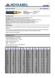
XHP 48, XHP 48-AN2XSY, NA2XSYMedium voltage cables with XLPE insulationStandard: SRPS N.C5.230Nominal voltage U 0 /U: 6/10 kV, 12/20 kV, 20/35 kVTest voltage: 15 kV, 30 kV, 50 kVCONSTRUCTIONConductor: multi-core copper (XHP 48) or aluminium (XHP 48-A)conductor class 2, according to SRPS N.C0.015.Inner semi-conductive layerInsulation: XLPE compound.Outer semi-conductive layer: extruded. Wrapped semiconductivetape over extruded layer, used as bedding for electricprotection.Electric protection: wrapped annealed copper wires with contrahelicalannealed copper tape or wrapped copper tape.Sheath: PVC compound.Sheath colour black, for use in mining red.APPLICATIONFor laying indoors, in ducts, directly in earth, in the open air indistribution networks, industrial plants and electric power plants,when additional mechanical damages are not expected.CONSTRUCTION DATA026nxq/q 1[mm 2 ]Cu number[kg/km]XHP 48 XHP 48-ADiameter[mm]Mass[kg/km]Al number[kg/km]Cu number[kg/km]Diameter[mm]Mass[kg/km]6/10 kV1x50/16 622 26,0 1010 145 182 26,0 6951x70/16 854 28,0 1266 203 182 28,0 8211x95/16 1094 29,5 1535 276 182 29,5 9311x120/16 1334 31,0 1792 348 182 31,0 10301x150/25 1723 32,5 2210 435 283 32,5 12391x185/25 2059 34,0 2534 537 283 34,0 14121x240/25 2587 35,5 3136 696 283 35,5 16111x300/25 3163 39,0 3851 870 283 39,0 189412/20 kV1x50/16 622 30,5 1238 145 182 30,5 9131x70/16 854 32,5 1458 203 182 32,5 9941x95/16 1094 33,0 1731 276 182 33,0 11481x120/16 1334 35,0 1984 348 182 35,0 12221x150/25 1723 37,0 2414 435 283 37,0 14671x185/25 2059 39,0 2854 537 283 39,0 16651x240/25 2587 41,5 3478 696 283 41,5 19171x300/25 3163 43,0 4028 870 283 43,0 205520/35 kV1x50/16 622 37,5 1598 145 182 37,5 12981x70/16 854 39,0 1877 203 182 39,0 14431x95/16 1094 40,0 2175 276 182 40,0 15801x120/16 1334 42,0 2453 348 182 42,0 17061x150/25 1723 43,0 2879 435 283 43,0 19321x185/25 2059 44,5 3240 537 283 44,5 21041x240/25 2587 48,0 3993 696 283 48,0 24691x300/25 3163 50,5 4602 870 283 50,5 2675n – number of the wires, q – nominal cross section of the conductor, q 1 – cross section of the electricalprotection
XHP 48, XHP 48-AN2XSEY, NA2XSEYMedium voltage power cables with XLPE insulationStandard: SRPS N.C5.230Nominal voltage U 0 /U: 6/10 kVTest voltage:15 kVCONSTRUCTIONConductor: multi-core copper (XHP 48) or aluminium (XHP 48-A)conductor class 2, according to SRPS N.C0.015.Inner semi-conductive layerInsulation: XLPE compound.Outer semi-conductive layer: extruded. Wrapped semiconductivetape over extruded layer, used as bedding for electricalprotection.Electric protection: wrapped annealed copper wires with contrahelicalannealed copper tape or wrapped copper tape.Core: 3 cores are stranded together.Filling: extruded, non hygroscopic layer over the core thatcompletely fills the space between the cores.Outer sheath: PVC compound.Sheath colour black, for use in mining red.APPLICATIONFor laying indoors, in ducts, directly in earth, in the open air indistribution networks, industrial plants and electric power plants.Laying down directly in the earth is limited by the mechanicalproperties of the PVC sheath.CONSRUCTION DATAnxq/q 1[mm 2 ]Cu number[kg/km]XHP 48 XHP 48-ADiameter[mm]Mass[kg/km]Al number[kg/km]Cu number[kg/km]Diameter[mm]Mass[kg/km]0276/10 kV3x50/16 1671 51,5 3714 435 231 51,5 27513x70/16 2247 55,5 4583 609 231 55,5 32363x95/16 2994 60,0 5703 827 258 60,0 38733x120/16 3714 62,5 6617 1044 258 62,5 43063x150/25 4603 68,0 7989 1305 315 68,0 50393x185/25 5611 69,5 9051 1610 315 69,5 54893x240/25 7272 76,5 11318 2088 362 76,5 66963x300/25 9160 80,0 13632 2610 520 80,0 7793n – number of the wires, q – nominal cross section of the conductor, q 1 – cross section of the electrical protectionPermissible conductor temperature:- operating temperature, max +90°C,- in short circuit (max 5 s), max +250°C.Permissible environment temperature:- at laying and handling, min +5°C.Smallest bending radius: 15D (D – cable diameter).
XHE 49, XHE 49-AN2XS(F)2Y, NA2XS(F)2YMedium voltage cables with XLPE insulation and longitudinally protection frommoistureStandard: SRPS N.C5.230Nominal voltage U 0 /U: 6/10 kV, 12/20 kV, 20/35 kVIspitni napon: 15 kV, 30 kV, 50 kVCONSTRUCTIONConductor: multi-core compacted copper (XHP49) or aluminium(XHP 49-A) conductor class 2, according to SRPS N.C0.015.Inner semi-conductive layer: extruded.Insulation: XLPE compound.Outer semi-conductive layer: extruded.Inner sealing layer: wrapped semi-conductive waterproof tape,used as bedding for electrical protection as well as additionalprotection of the insulation from water penetration along thescreen.Electrical protection: wrapped annealed copper wires withcontra-helical annealed copper tape or wrapped copper tape.Layer: wrapped waterproof tape.Sheath: special PE compound.Sheath colour black.APPLICATIONCONSTRUCTION DATAIn distributing network mains, industrial plants, middle-voltage andhigh voltage switchgear assemblies, thermo-power plants andelectric power plants, when cables are exposed to aggressive andwet surrounding effects. For laying indoors, in ducts, in the open air,on cable trays, in earth and in the water.028nxq/q 1[mm 2 ]Cu number[kg/km]XHE 49 XHE 49-ADiameter[mm]Mass[kg/km]Al number[kg/km]Cu number[kg/km]Diameter[mm]Mass[kg/km]6/10 kV1x95/16 1094 31,0 1490 276 182 31,0 8851x120/16 1334 32,0 1701 348 182 32,0 10051x150/25 1723 32,5 2136 435 283 32,5 11621x185/25 2059 34,5 2468 537 283 34,5 12931x240/25 2587 37,5 3058 696 283 37,5 15331x300/25 3163 41,5 3700 870 283 41,5 179712/20 kV1x95/16 1094 34.5 1700 276 182 34,5 10901x120/16 1334 36,0 2036 348 182 36,0 12421x150/25 1723 38,0 2270 435 283 38,0 13791x185/25 2059 41,5 2695 537 283 41,5 16101x240/25 2587 42,0 3280 696 283 42,0 17541x300/25 3163 45,0 3960 870 283 45,0 204320/35 kV1x95/16 1094 42,5 2051 276 182 42,5 14651x120/16 1334 44,0 2310 348 182 44,0 15081x150/25 1723 45,0 2742 435 283 45,0 17681x185/25 2059 48,5 3185 537 283 48,5 19851x240/25 2587 52,5 3865 696 283 52,5 23061x300/25 3163 49,0 4280 870 283 49,0 2569n – number of the wires, q – nominal cross section of the conductor, q 1 – cross section of the electricalprotection
XHEh 91, XHEh 91-AMedium voltage cables with XLPE insulation and additional electricalprotectionStandard: SRPS N.C5.230Nominal voltage U 0 /U: 6/10 kV, 12/20 kV, 20/35 kVTest voltage: 15 kV, 30 kV, 50 kVCONSTRUCTIONKONSTRUKCIIJJAConductor: multi-core copper (XHEh 91) or aluminium (XHEh91-A) compacted conductor class 2, according to SRPS N.C0.015.Inner semi-conductive layer: extruded.Insulation: XLPE compound.Outer semi-conductive layer: extruded.Inner sealing layer: wrapped semi-conductive, waterprooftape, used as bedding for electric protection as well as additionalprotection to the insulation from the break along the screen.Electric protection: wrapped annealed copper wires withcontra-helical annealed copper tape or wrapped copper tape.Sealing layer: wrapped semi-conductive, waterproof tape.Outer sheath: semi-conductive PE compound.Additional electric protection: wrapped tinned copper wires,as single-layer or double-layer: subject to cross-section needed.APPLICATIONFor laying in earth or on supports. The cable bears medium axialtensile strains. In medium-voltage distributing network mains,when the cable is laying in area with high ground conductivity, forprotection of electric power plants from over-voltages caused bylightning or other failures at high-voltage transmission network.Additional electric protection is rated in dependence on the request, i.e., exploit conditions. Allother data are the same as for cable type XHE 49. The same is valid for electric features andpermitted current ratings, as well as permitted short circuit current for phase conductor.Permitted short circuit current for electric protection of cable depends on cross-section ofadditional electric protection.029Electric protection and additional protection must be joined each other, leastwise at cableclamps and cable heads.The data cable is provided to an individual user request.
XHP 81, XHP 81-AN2XSYBY, NA2XSYBYN2XSEYBY, NA2XSEYBYMedium voltage cables with XLPE insulation and mechanical protectionStandard: SRPS N.C5.230Nominal voltage U 0 /U: 6/10 kVTest voltage:15 kVCONSTRUCTIONConductor: multi-core copper (XHP 81) or aluminium (XHP 81-A)conductor class 2, according to SRPS N.C0.015.Inner semi-conductive layer: extruded.Insulation: XLPE compound.Outer semi-conductive layer: extruded, with wrapped semiconductivetape over extruded layer.Electric protection: wrapped annealed copper wires with contrahelicalannealed copper tape or wrapped copper tape.Core: 3 cores are stranded together.Separate sheath: extruded, non hygroscopic layer over the corethat completely fills the space between the cores.Armour: wrapped two steel tapes.Outer sheath: PVC compound.Sheath colour black, for use in mining red.APPLICATIONFor laying indoors, in ducts, in the open air, directly in earth, inurbane networks, industrial plants and power plants. Suitable for thenetworks which require minor reduction factor. Not provided forcomplicated conditions in terms of severe axial strains.CONSTRUCTION DATA030nxq/q 1[mm 2 ]Cu number[kg/km]XHP 81 XHP 81-ADiameter[mm]Mass[kg/km]Al number[kg/km]Cu number[kg/km]Diameter[mm]Mass[kg/km]3x50/16 1671 50,5 4554 435 231 55,5 42273x70/16 2247 55,5 5517 609 231 61,0 50463x95/16 2994 61,0 6862 827 258 63,0 56673x120/16 3714 63,0 7432 1044 258 66,5 62373x150/25 4603 66,5 8952 1305 315 70,0 71533x185/25 5611 70,0 10479 1610 315 75,5 81873x240/25 7272 75,5 12865 2088 362 83,5 9431n – number of the wire, q – nominal cross section of the conductor, q 1 – cross section of the electricalprotectionPermissible conductor temperature:- operating temperature (constant load), max +90°C,- in short circuit (max 5 s), max +250°C.Permissible environment temperature:- at laying and handling, min +5°C.Smallest bending radius: 15D (D – cable diameter).
XHP 84, XHP 84-AN2XSYRGY, NA2XSYRGYN2XSEYRGY, NA2XSEYRGYMedium voltage cables with XLPE insulation and mechanical protectionStandard: SRPS N.C5.230Nominal voltage U 0 /U: 6/10 kVTest voltage:15 kVCONSTRUCTIONConductor: multi-core annealed copper (XHP 84) or aluminium(XHP 84-A) conductor class 2, according to SRPS N.C0.015.Inner semi-conductive layerInsulation: XLPE compound.Outer semi-conductive layer: extruded, strongly attached toinsulation, with lapped semi-conductive tape over extruded layerused as bedding for electric protection.Electric protection: wrapped annealed copper wires with contrahelicalannealed copper tape or wrapped copper tape.Core: 3 cores are stranded together.Separate sheath: extruded, non hygroscopic layer over the corethat completely fills the space between the cores.Armour: wrapped round zinc-plated steel wires with or withoutcontra-helical zinc-plated steel tapeOuter sheath: PVC compound.Sheath colour black, for use in mining red.APPLICATIONIn urban networks, industrial plants and power plants, when thecable is exposed to severe mechanical tensile strains during layingdown or use. For laying in ducts, in the open air and in earth.CONSTRUCTION DATAnxq/q 1[mm 2 ]Cu number[kg/km]XHP 84 XHP 84-ADiameter[mm]Mass[kg/km]Al number[kg/km]Cu number[kg/km]Diameter[mm]Mass[kg/km]0313x50/16 1671 53,5 5979 435 231 53,5 47713x70/16 2247 59,5 7259 609 231 59,5 56593x95/16 2994 61,5 8155 827 258 61,5 62813x120/16 3714 65,0 9494 1044 258 65,0 75503x150/25 4603 71,5 11327 1305 315 71,5 84693x185/25 5611 76,0 13476 1610 315 76,0 101363x240/25 7272 81,0 15870 2088 362 81,0 11360n – number of the wire, q – nominal cross section of the conductor, q 1 – cross section of the electricalprotectionPermissible conductor temperature:- operating temperature (constant load), max +90°C,- in short circuit (max 5 s), max +250°C.Permissible environment temperature:- at laying and handling, min +5°C.Smallest bending radius: 15D (D – cable diameter).
XHP 85, XHP 85-AN2XSYFGY, NA2XSYFGYN2XSEYFGY, NA2XSEYFGYMedium voltage cables with XLPE insulation and mechanical protectionStandard: SRPS N.C5.230Nominal voltage U 0 /U: 6/10 kVTest voltage:15 kVCONSTRUCTIONConductor: multi-core annealed copper (XHP 85) or aluminium(XHP 85-A) conductor class 2, according to SRPS N.C0.015.Inner semi-conductive layer: extruded.Insulation: XLPE compound.Outer semi-conductive layer: extruded, with lapped semiconductivetape over extruded layer used as bedding for electricprotection.Electric protection: wrapped annealed copper wires with contrahelicalannealed copper tape or wrapped copper tape.Core: 3 cores are stranded together.Separate sheath: extruded, non hygroscopic layer over the corethat completely fills the space between the cores.Armour: wrapped flat zinc-plated steel wires with contra-helicalzinc-plated steel tapeOuter sheath: PVC compound.Sheath colour black, for use in mining red.APPLICATIONIn urban networks, industrial plants and power plants, when thecable is exposed to severe mechanical tensile strains during layingdown or use. For laying in ducts, in the open air and in earth.CONSTRUCTION DATA032nxq/q 1[mm 2 ]Cu number[kg/km]XHP 85 XHP 85-ADiameter[mm]Mass[kg/km]Al number[kg/km]Cu number[kg/km]Diameter[mm]Mass[kg/km]3x50/16 1671 51,5 4635 435 231 51,5 38783x70/16 2247 54,5 5536 609 231 54,5 44143x95/16 2994 60,0 6606 827 258 60,0 52723x120/16 3714 63,5 7450 1044 258 63,5 58923x150/25 4603 65,5 8852 1305 315 65,5 64713x185/25 5611 69,0 10257 1610 315 69,0 72773x240/25 7272 81,0 13870 2088 362 75,0 84393x300/25 9160 82,0 15491 2610 520 82,0 9722n – number of the wire, q – nominal cross section of the conductor, q 1 – cross section of the electricalprotectionPermissible conductor temperature:- operating temperature (constant load), max +90°C,- in short circuit (max 5 s), max +250°C.Permissible environment temperature:- at laying and handling, min +5°C.Smallest bending radius: 15D (D – cable diameter).
0033
POWERCONDUCTORSH07V-U, -R 035 H03VH-H 040NYM 036 H03VV-F 041PP-R 037 H05VV-F 042PP-U 038 PP-JZ 043H07V-K 039 H05VVH6-F 044
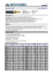
PH07V-U, H07V-RInstallation cable with PVCStandard: SRPS N.C3.200Nominal voltage U 0 /U: 450/750 VTest voltage:2,5 kVCONSTRUCTIONConductor: solid annealed copper conductor class 1 or multicoreannealed copper conductor class 2, according to SRPSN.C0.015.Insulation: PVC compound.Insulation colour black, blue, brown, green/yellow.APPLICATIONFor fixed electric power installations in dry conditions, drawn intubes, on plaster or under the plaster, or laid on insulators overplaster.CONSTRUCTION DATAn x qCu number Diameter Mass[mm 2 ] [kg/km] [mm] [kg/km]1,5 14.4 2,8 202,5 24 3,5 314 38 4,0 466 58 4,5 6610 96 5,5 10710 96 6,0 11616 154 7,0 17225 240 8,6 26835 336 9,7 36303550 480 11,3 49470 672 14,0 72595 912 15,3 959120 1152 16,2 1194150 1440 18,2 1498185 1776 22,3 1912240 2304 25,0 2433300 2880 27,9 3041400 3840 31,6 3915n – number of the wire, q – nominal cross section of the conductorPermissible conductor temperature:- operating temperature, max +70°C,- in short circuit (max 5 s), max +160°C.Permissible environment temperature:- at laying and handling, min +5°C.Smallest bending radius: 12D - 15 D (D – cable diameter).
PPNYMInstallation cable with PVCStandard: SRPS N.C3.220Nominal voltage U 0 /U: 300/500 VTest voltage:2 kVCONSTRUCTIONConductor: annealed copper wire class 1 or strand class 2,according to SRPS N.C0.015.Insulation: PVC compound.Core: two or more cores are stranded together.Filling: non vulcanized rubber compound layer is over the core.Sheath: PVC compound.Sheath colour grey.APPLICATIONIn dry and wet conditions indoors and in the open air, for laying onplaster, in plaster or under plaster. Cable is suitable forinstallations in food industries, laundries and so on.CONSTRUCTION DATA036n x q Cu number Diameter Mass n x q Cu number Diameter Mass[mm 2 ] [kg/km] [mm] [kg/km] [mm 2 ] [kg/km] [mm] [kg/km]2x1,5 29 8,5 110 4x1,5 58 10,0 1512x2,5 48 9,8 148 4x2,5 96 11,0 2132x4 77 10,9 202 4x4 154 13,0 3082x6 115 2,6 288 4x6 230 14,5 4102x10 192 16,0 467 4x10 384 17,5 6452x16 308 18,5 669 4x16 614 21,0 9782x25 480 21,5 936 4x25 960 25,0 14962x35 672 24,5 1295 4x35 1344 27,5 19893x1,5 43 9,0 129 5x1,5 72 10,5 1823x2,5 72 10,5 178 5x2,5 120 12,0 2603x4 115 12,5 243 5x4 192 14,0 3753x6 173 14,0 332 5x6 288 15,5 4983x10 288 17,0 571 5x10 480 19,0 7953x16 461 19,5 828 5x16 768 25,0 12333x25 720 26,0 1297 5x25 1200 28,0 18333x35 1008 29,5 1700 5x35 1680 35,5 2578n – number of the wire, q – nominal cross section of the conductorPermissible conductor temperature:- operating temperature, max +70°C,- in short circuit (max 5 s), max +160°C.Permissible environment temperature:- at laying and handling, min +5°C.Smallest bending radius for permanently laid cable: 6D (D - cable diameter).
PP/RInstallation cable with PVCStandard: SRPS N.C3.230Nominal voltage: 380 VTest voltage: 2 kVCONSTRUCTIONConductor: annealed copper wire class 1, according to SRPSN.C0.015.Insulation: PVC compound.Sheath: PVC compound layer over 2 or 3 cores, which are laidparallel. The layer is forming the track between the cores, withthe notch in the middle of the track, this making possibletemporary fixing of the cables.Sheath colour can be grey or black.APPLICATIONIn dry conditions indoors, for laying in plaster or under plaster,without special mechanical protection. Suitable for installations inobjects made of prestressed concrete, vibrated concrete orprefabricated elements, when the notches for laying the roundcables can not be made. Not for use in wooden object, nor in openair.CONSTRUCTION DATAn x qCu number Height x width Mass[mm 2 ] [kg/km] [mm] [kg/km]2x1,5 29 4,4x12,0 662x2,5 48 5,2x13,5 983x1,5 43 4,4x19,5 1043x2,5 72 5,2x22,5 151037n – number of the wire, q – nominal cross section of the conductorPermissible conductor temperature:- operating temperature, max +70°C,- in short circuit (max 5 s), max +160°C.Permissible environment temperature:- at laying and handling, min +5°C.Smallest bending radius: 4a (a – cable height).
PP/UFlat installation cable with PVCStandard: SRPS N.C3.235Nominal voltage U 0 /U: 300/500 VTest voltage:2 kVCONSTRUCTIONConductor: annealed copper wire class 1 or strand class 2,according to SRPS N.C0.015.Insulation: PVC compound.Core: two or more cores are laid side by side.Sheath: PVC compound.Sheath colour grey.APPLICATIONIn dry and wet conditions indoors, for permanent laying on plaster,in plaster or under plaster, or on steel constructions.CONSTRUCTION DATA038n x q[mm 2 ]CunumberWidth xheightMass[kg/km] [mm] [kg/km]n x q[mm 2 ]CunumberWidth xheightMass[kg/km] [mm] [kg/km]2x1 19 8,2x5,6 57 3x1 29 11,4x6,2 852x1,5 29 8,8x5,9 68 3x1,5 43 12,3x6,5 1052x2,5 48 10,0x6,5 112 3x2,5 72 14,1x7,1 1852x4 77 12,2x7,9 145 3x4 115 16,7x8,1 2172x6 115 13,2x8,4 191 3x6 173 18,2x8,6 286n – number of the wire, q – nominal cross section of the conductorPermissible conductor temperature:- operating temperature, max +70°C,- in short circuit (max 5 s), max +160°C.Permissible environment temperature:- at laying and handling, min +5°C.Smallest bending radius: 4a (a – cable height).
P/FH07V-KFlexible installation cable with PVCStandard: SRPS N.C3.202Nominal voltage U 0 /U: 450/750 VTest voltage:2,5 kVCONSTRUCTIONConductor: flexible strand or rope consists of annealed copperwires class 5, according to SRPS N.C0.015.Insulation: PVC compound.Insulation colour black, blue, brown, green/yellow.APPLICATIONFor usage in dry conditions where extra flexibility is require. Cableinstalls in tubes, over or under the plaster, or lay on insulatorsover plaster. Nominal cross-sections cable 0,5 mm 2 and 0,75 mm 2are intended only for installations of equipments and distributionnetworks.CONSTRUCTION DATAn x q Cu number Diameter Mass n x q Cu number Diameter Mass[mm 2 ] [kg/km] [mm] [kg/km] [mm 2 ] [kg/km] [mm] [kg/km]0,5 4,8 2,2 9 25 240 9,3 2720,75 7,2 2,3 12 35 336 11,1 3721 9,6 2,5 14 50 480 13,4 5321,5 14.4 3,1 20 70 672 15,3 7592,5 24,0 3,8 33 95 912 18,3 10034 38,0 4,3 48 120 1152 19,2 12566 58,0 4,8 70 150 1440 20,3 149610 96,0 6,5 117 185 1776 22,7 182916 154 7,9 184 240 2304 26,6 2455039n – number of the wire, q – nominal cross section of the conductorPermissible conductor temperature:- operating temperature, max +70°C,- in short circuit (max 5 s), max +160°C.Permissible environment temperature:- at laying and handling, min +5°C.Smallest bending radius: 5 D (D – cable diameter).
P/LH03VH-HFlexible cable with PVCStandard: SRPS N.C3.300Nominal voltage U 0 /U: 300/300 VTest voltage:2 kVCONSTRUCTIONConductor: flexible strand consists of annealed copper wiresclass 5, according to SRPS N.C0.015.Insulation: common PVC compound layer over two or threeparallel laid conductors, which can be easily separated, withoutdamaging the insulation.Sheath colour not defined all colours possible, transparent aswell.APPLICATIONIn dry rooms, for connecting of small mobile electric appliances,such as table lamps, wireless sets, table fans and so forth. It isadvisable to protect the cable inlet place with a rubber orthermoplastic sleeve.CONSTRUCTION DATAn x qCu number Height x width Mass[mm 2 ] [kg/km] [mm] [kg/km]2x0,5 9,6 2.6x5,2 222x0,75 14,4 3,0x6,0 282x1 19.0 3,0x6,0 330403x0,5 14,4 2,6x7,8 333x0,75 21,6 2,8x8,4 423x1 29.0 3,0x9,0 50n – number of the wire, q – nominal cross section of the conductorPermissible conductor temperature:- operating temperature, max +70°C,- in short circuit (max 5 s), max +160°C.Permissible environment temperature:- at laying and handling, min +5°C.Smallest bending radius: 5a (a – cable height).
PP/LH03VV-FFlexible cable with PVCStandard: SRPS N.C3.301Nominal voltage U 0 /U: 300/300 VTest voltage:2 kVCONSTRUCTIONConductor: flexible strand consists of annealed copper wiresclass 5, according to SRPS N.C0.015.Insulation: PVC compound.Core: 2 or 4 cores are stranded together.Sheath: PVC compound.Sheath colour can be white, grey or black.APPLICATIONIn dry rooms, for connecting of small mobile electric appliances,such as table lamps, wireless sets, television sets, table fans andso forth, when the cord can be exposed to minor mechanicaltensile strains.CONSTRUCTION DATAn x qCu number Diameter Mass[mm 2 ] [kg/km] [mm] [kg/km]2x0,5 9,6 5,5 352x0,75 14,4 5,7 442x1 19 6,0 523x0,5 14,4 5,5 433x0,75 21,6 6,0 533x1 29 6,5 644x0,5 19,2 6,0 544x0,75 29 6,7 664x1 38 6,9 78041n – number of the wire, q – nominal cross section of the conductorPermissible conductor temperature:- operating temperature, max +70°C,- in short circuit (max 5 s), max +160°C.Permissible environment temperature:- at laying and handling, min +5°C.Smallest bending radius: 5 D (D – cable diameter).
PP/JH05VV-FFlexible cable with PVCStandard: SRPS N.C3.302Nominal voltage U 0 /U: 300/500 VTest voltage:2 kVCONSTRUCTIONConductor: flexible strand consists of annealed copper wiresclass 5, according to SRPS N.C0.015.Insulation: PVC compound.Core: 2 or 5 cores are stranded together.Sheath: PVC compound. Separation layer can be laid beneaththe sheath.Sheath colour can be white, grey or black.APPLICATIONFor connecting of mobile electrical appliances under hardoperational conditions, such as washing machines, vacuumcleaners. For connecting of thermal apparatus and domesticappliances if not in contact with heated surface over 85°C.CONSTRUCTION DATAn x q Cu number Diameter Mass n x q Cu number Diameter Mass[mm 2 ] [kg/km] [mm] [kg/km] [mm 2 ] [kg/km] [mm] [kg/km]2x0,75 15 6,4 55 4x0,75 29 7,4 782x1,0 19 6,8 63 4x1,0 38 7,9 892x1,5 29 7,5 80 4x1,5 58 9,3 1322x2,5 48 9,5 130 4x2,5 96 11,5 2010423x0,75 22 7,0 64 5x0,75 36 8,4 1003x1,0 29 7,1 73 5x1,0 48 8,7 1143x1,5 43 8,6 104 5x1,5 72 11,0 1653x2,5 72 10,5 163 5x2,5 120 12,7 253n – number of the wire, q – nominal cross section of the conductorPermissible conductor temperature:- operating temperature, max +70°C,- in short circuit (max 5 s), max +160°C.Permissible environment temperature:- at laying and handling, min +5°C.Smallest bending radius: 7 D (D – cable diameter).
PP/JZFlexible cable with electrical protectionStandard: PSNNominal voltage U 0 /U: 300/500 VTest voltage:2 kVCONSTRUCTIONConductor: flexible copper strand class 5, according to SRPSN.C0.015.Insulation: PVC compound.Core: 2 to 5 cores are stranded together.Filling: suitable material.Electric protection: braid of bare or tinned copper wires.Sheath: PVC compound.Sheath colour can be white, grey or black.APPLICATIONFor connection of mobile user devices at medium mechanicaltensile strains, where one cannot expect mechanical damages andelectric shock risk, near data processing and data transfer devicesand cables.CONSTRUCTION DATAn x q Cu number Diameter Mass n x q Cu number Diameter Mass[mm 2 ] [kg/km] [mm] [kg/km] [mm 2 ] [kg/km] [mm] [kg/km]2x0,75 15 8,7 105 4x0,75 29 10,2 1432x1,0 19 9,5 120 4x1,0 38 11,0 1702x1,5 29 9,8 133 4x1,5 58 11,7 2052x2,5 48 12,4 210 4x2,5 96 14,0 3053x0,75 22 9,3 120 5x0,75 36 11,0 1703x1,0 29 10,0 140 5x1,0 48 11,8 2003x1,5 43 11,0 175 5x1,5 72 11,9 2353x2,5 72 13,1 250 5x2,5 120 15,2 355043n – number of the wire, q – nominal cross section of the conductorPermissible conductor temperature:- operating temperature, max +70°C,- in short circuit (max 5 s), max +160°C.Permissible environment temperature:- at laying and handling, min +5°C.Smallest bending radius: 5D (D – cable diameter).
DPP/UH05VVH6-FEspecially flexible flat cable for cranesStandard: PSNNominal voltage U 0 /U: 300/500 VTest voltage:2 kVCONSTRUCTIONConductor: flexible copper strand class 6, according to SRPSN.C0.015.Insulation: PVC compound.Core formation: cores are arranged in groups of 2, 3 or 4 coreslaid side by side.Sheath: PVC compound.Sheath colour, grey or black.APPLICATIONIn dry and wet conditions as control cable in lifts, cranes,transported lines, machine tools, at medium mechanical tensilestrain, when the cable is exposed to severe bending in one plane.CONSTRUCTION DATAn x qCu number Width x height Mass[mm 2 ] [kg/km] [mm] [kg/km]0444x1 38 12,2x4,4 1056x1 57 18,4x4,4 1599x1 86 29,0x4,5 23212x1 115 35,0x4,5 32614x1 133 43,1x4,5 353n – number of the wire, q – nominal cross section of the conductorPermissible conductor temperature:- operating temperature, max +70°C,- in short circuit (max 5 s), max +160°C.Permissible environment temperature:- at laying and handling, min +5°C.Smallest bending radius: 4a (a – cable height).
045
SIGNAL <strong>CABLES</strong>NYY 047 NYSLY 052NYBY 048 NYSLYCY 053NYRGY 049 NYSLYÖ(H05VV5-F) 054NYSY 050 NYSLYCYÖ(H05VVC4V5-F) 055N2XY 051 SEZ 056SPZ 057
PP 00NYYSignal cable with PVCStandard: SRPS N.C5.220Nominal voltage U 0 /U: 0,6/1 kVTest voltage:3,5 kVCONSTRUCTIONConductor: annealed copper wire.Insulation: PVC compound.Core: cores are stranded together, concentric laid.Filling: wrapped thermoplastic tapes or extruded non vulcanizedrubber compound layer.Sheath: PVC compound.Sheath colour black.APPLICATIONIn earth, ducts, in the open air, in industrial plants, electric powerplants, for connection of control devices in industry and traffic,where one cannot expect mechanical damages. When controlcables are parallel laid along with power cables and overhead lines,the care must be taken about those cables' influence to signalsbeing transmitted.CONSTRUCTION DATAnxq Cu number Diameter Mass nxq Cu number Diameter Mass[mm 2 ] [kg/km] [mm] [kg/km] [mm 2 ] [kg/km] [mm] [kg/km]7x1,5 101 13,0 252 7x2,5 168 15,0 3478x1,5 115 14,0 290 8x2,5 192 16,0 40810x1,5 144 16,5 345 10x2,5 240 19,0 47812X1,5 173 17,0 392 12X2,5 288 19,0 55914X1,5 202 17,5 441 14X2,5 336 20,0 63516X1,5 230 18,5 500 16X2,5 384 21,0 72019X1,5 274 19,5 570 19X2,5 456 22,5 81321X1,5 302 20,0 630 21X2,5 504 23,5 89924X1,5 346 22,5 708 24X2,5 576 26,0 105130X1,5 432 24,0 851 30X2,5 720 28,0 123937X1,5 533 26,0 1040 37X2,5 888 30,0 155240X1,5 576 27,0 1114 40X2,5 960 31,5 162752X1,5 749 30,5 1397 52X2,5 1248 35,0 210561X1,5 878 32,0 1671 61X2,5 1464 38,0 2471047n – number of the cores, q – nominal cross section conductorPermissible conductor temperature:- operating temperature, max +70°C.Permissible environment temperature:- at laying and handling, min +5°C.Smallest bending radius: 15 D (D – cable diameter).
PP 41NYBYSignal cable with PVCStandard: SRPS N.C5.220Nominal voltage U 0 /U: 0,6/1 kVTest voltage:3,5 kVCONSTRUCTIONConductor: annealed copper wire.Insulation: PVC compound.Core: cores are stranded together, concentric laid.Filling: extruded non vulcanized rubber compound layer.Armour: wrapped two steel tapes.Sheath: PVC compound.Sheath colour black.APPLICATIONFor connection of control devices in industry, thermo- and hydroelectricpower plants, when additional mechanical protection isrequired. For laying directly in earth, in ducts and in the open air.CONSTRUCTION DATAnxq Cu number Diameter Mass nxq Cu number Diameter Mass[mm 2 ] [kg/km] [mm] [kg/km] [mm 2 ] [kg/km] [mm] [kg/km]0487x1,5 101 16,0 433 7x2,5 168 18,0 5528x1,5 115 17,0 484 8x2,5 192 19,0 61910x1,5 144 19,5 508 10x2,5 240 21,5 75612X1,5 173 20,0 694 12X2,5 288 22,5 89514X1,5 202 20,5 810 14X2,5 336 23,5 106616X1,5 230 21,5 893 16X2,5 384 24,0 120019X1,5 274 22,5 974 19X2,5 456 26,0 133221X1,5 302 23,5 1052 21X2,5 504 27,0 144224X1,5 346 26,0 1201 24X2,5 576 29,5 161030X1,5 432 27,5 1279 30X2,5 720 31,0 166237X1,5 533 29,0 1412 37X2,5 888 34,0 218140X1,5 576 30,0 1690 40X2,5 960 35,5 234952X1,5 749 34,5 2244 52X2,5 1248 39,5 289761X1,5 878 36,0 2344 61X2,5 1464 41,5 3276n – number of the cores, q – nominal cross section conductorPermissible conductor temperature:- operating temperature, max +70°C.Permissible environment temperature:- at laying and handling, min +5°C.Smallest bending radius: 15 D (D – cable diameter).
PP 44NYRGYSignal cable with PVCStandard: SRPS N.C5.220Nominal voltage U 0 /U: 0,6/1 kVTest voltage:3,5 kVCONSTRUCTIONConductor: annealed copper wire.Insulation: PVC compound.Core: cores are stranded together, concentric laid.Filling: extruded non vulcanized rubber compound layer orthermoplastic compound layer.Armour: wrapped round zinc-plated steel wires with or withoutcontra helical zinc-plated steel tape (obligatory when cable isused in mines).Sheath: PVC compound.Sheath colour black.APPLICATIONFor connection of control devices. For laying directly in ground, incable ducts and in air in industrial plants, power plants, under thetraffic lines and along the traffic lines, when the cable is exposedto increased mechanical tensile strain during laying or use.Suitable for vertical or inclined laying along with cable clamps atappropriate distances and with appropriate self-supportingcoefficient. For use in mines.CONSTRUCTION DATAConstruction Cu number Diameter Mass Construction Cu number Diameter Massnxq [kg/km] [mm] [kg/km]nxq [kg/km] [mm] [kg/km]7x1,5 101 17,0 539 7x2,5 168 20,0 8708x1,5 115 19,0 764 8x2,5 192 20,0 83010x1,5 144 20,5 741 10x2,5 240 24,0 109512X1,5 173 21,5 872 12X2,5 288 25,0 139214X1,5 202 21,0 854 14X2,5 336 25,5 126916X1,5 230 23,0 1060 16X2,5 384 27,0 143019X1,5 274 24,0 1146 19X2,5 456 28,5 176721X1,5 302 26,0 1294 21X2,5 504 29,0 167324X1,5 346 27,0 1513 24X2,5 576 32,0 220030X1,5 432 29,5 1627 30X2,5 720 33,5 230037X1,5 533 32,0 1785 37X2,5 888 36,0 268140X1,5 576 31,5 1915 40X2,5 960 37,0 289352X1,5 749 38,0 2650 52X2,5 1248 43,0 352061X1,5 878 40,0 2950 61X2,5 1464 45,0 3910049n – number of the cores, q – nominal cross section conductorPermissible conductor temperature:- operating temperature, max +70°C.Permissible environment temperature:- at laying and handling, min +5°C.Smallest bending radius: 15 D (D – cable diameter).
PP 47NYSYSignal cables with PVCStandard: SRPS N.C5.220Nominal voltage U 0 /U: 0,6/1 kVTest voltage:3,5 kVCONSTRUCTIONConductor: annealed copper wire.Insulation: PVC compound.Core: cores are stranded together, concentric laid.Filling: extruded non vulcanized rubber compound layer orthermoplastic compound layer.Electrical protection: wrapped annealed copper tape.Sheath: PVC compound.Sheath colour black.APPLICATIONFor connection of control devices in industry, thermo- and hydroelectricpower plants, when additional electrical protection isrequired. The cable is protected from the influence of externalinterference of adjacent power conductors. Cable can laying inearth, ducts, in the open air, where one cannot expect mechanicaldamages.CONSTRUCTION DATA050Construction Cu number Diameter Mass Construction Cu number Diameter Massnxq [kg/km] [mm] [kg/km] nxq [kg/km] [mm] [kg/km]7x1,5 165 15,5 374 7x2,5 242 16,0 4338x1,5 185 15,0 362 8x2,5 273 18,5 55710x1,5 226 18,5 516 10x2,5 336 21,0 76012X1,5 257 17,5 481 12X2,5 387 20,5 73514X1,5 291 20,5 642 14X2,5 440 22,5 83116X1,5 324 19,0 600 16X2,5 494 23,5 93019X1,5 373 20,0 675 19X2,5 572 23,0 95421X1,5 407 21,0 740 21X2,5 627 26,5 116724X1,5 462 25,0 947 24X2,5 713 29,0 133230X1,5 556 24,5 1004 30X2,5 866 29,0 143437X1,5 667 26,5 1197 37X2,5 1048 31,0 172140X1,5 715 27,5 1286 40X2,5 1127 32,0 185352X1,5 909 31,0 1599 52X2,5 1438 36,5 235861X1,5 1049 33,0 1828 61X2,5 1666 38,5 2704n – number of the cores, q – nominal cross section conductorPermissible conductor temperature:- operating temperature, max +70°C.Permissible environment temperature:- at laying and handling, min +5°C.Smallest bending radius: 15 D (D – cable diameter).
XP 00N2XYSignal cable with XLPE insulationStandard: SRPS N.C5.230Nominal voltage U 0 /U: 0,6/1 kVTest voltage:3,5 kVCONSTRUCTIONConductor: annealed copper wire.Insulation: XLPE compound.Core: cores are stranded together, concentric laid.Filling: wrapped thermoplastic tapes or extruded non vulcanizedrubber compound layer.Sheath: PVC compound.Sheath colour black.APPLICATIONIn earth, ducts, in the open air, in industrial plants, electric powerplants, for connection of control devices in industry and traffic,where one cannot expect mechanical damages. When controlcables are parallel laid along with power cables and overhead lines,the care must be taken about those cables' influence to signalsbeing transmitted.CONSTRUCTION DATAConstruction Cu number Diameter Mass Construction Cu number Diameter Massnxq [kg/km] [mm] [kg/km] nxq [kg/km] [mm] [kg/km]7x1,5 101 12,5 213 7x2,5 168 13,5 2918x1,5 115 13,5 242 8x2,5 192 14,5 33310x1,5 144 15,5 281 10x2,5 240 17,0 40212X1,5 173 15,5 330 12X2,5 288 17,5 46214X1,5 202 16,5 373 14X2,5 336 18,0 52416X1,5 230 17,5 420 16X2,5 384 19,0 59419X1,5 274 18,0 477 19X2,5 456 20,0 68021X1,5 302 19,0 524 21X2,5 504 21,0 74924X1,5 346 21,0 591 24X2,5 576 23,5 84630X1,5 432 22,0 709 30X2,5 720 25,0 104637X1,5 533 24,5 873 37X2,5 888 27,0 126240X1,5 576 25,0 939 40X2,5 960 28,0 136052X1,5 749 28,5 1182 52X2,5 1248 31,5 172361X1,5 878 30,0 1361 61X2,5 1464 33,5 1993051n – number of the cores, q – nominal cross section conductorPermissible conductor temperature:- operating temperature, max +90°C.Permissible environment temperature:- at laying and handling, min +5°C.Smallest bending radius: 15 D (D – cable diameter).
NYSLY, NYSLY- JZFlexible signal cableStandard: DIN VDE 0245 part 102Nominal voltage U 0 /U: 300/500 VTest voltage:2 kVCONSTRUCTIONConductor: annealed copper stranded class 5, according to DINVDE 0295.Insulation: special PVC compound.Core: cores are stranded together, concentric laid. The cores areblack, marked with numbers. When green/yellow core exists(type code: -JZ), it is laid in outer layer.Sheath: special PVC compound.Sheath colour grey.APPLICATIONIn dry and wet conditions as supply cable or remote control andsignal cable in assembling lines, machine tools, automatics, etc.,at medium mechanical strains. Not designed for laying in the openair.CONSTRUCTION DATA052n x q Cu number Diameter Mass n x q Cu number Diameter Mass n x q Cu number Diameter Mass[mm 2 ] [kg/km] [mm] [kg/km] [mm 2 ] [kg/km] [mm] [kg/km] [mm 2 ] [kg/km] [mm] [kg/km]3x0,5 14.4 6,3 53 3x0,75 22 6,8 64 3x1 29 7,2 754x0,5 20 6,9 63 4x0,75 29 7,4 77 4x1 39 7,9 915x0,5 24 7,5 74 5x0,75 36 8,5 98 5x1 48 9,0 1167x0,5 34 9,1 101 7x0,75 51 9,6 124 7x1 68 10,1 14812x0,5 58 11,5 171 12x0,75 87 12,3 212 12x1 116 13,2 25219x0,5 92 13,3 240 19x0,75 137 14,3 301 19x1 183 16,0 38325x0,5 120 16,1 337 25x0,75 180 17,3 420 25x1 240 19,1 52827x0,5 130 16,4 352 27x0,75 195 17,7 440 27x1 260 19,5 55334x0,5 164 18,8 442 34x0,75 245 20,1 551 34x1 327 21,5 66137x0,5 178 19,2 473 37x0,75 267 20,5 591 37x1 356 22,1 71044x0,5 211 21,5 567 44x0,75 317 23,2 709 44x1 422 25,4 88550x0,5 240 22,0 643 50x0,75 360 23,7 804 50x1 480 25,3 96561x0,5 293 23,8 752 61x0,75 439 25,7 945 61x1 586 28,1 11743x1,5 44 7,9 94 3x2,5 72 9,8 1524x1,5 58 8,8 122 4x2,5 96 11,1 1975x1,5 72 9,6 145 5x2,5 120 11,9 2347x1,5 101 11,3 197 7x2,5 168 13,3 30312x1,5 173 14,0 320 12x2,5 288 18,0 52219x1,5 274 17,0 488 19x2,5 456 21,6 78825x1,5 360 20,3 669 25x2,5 600 25,8 107427x1,5 389 20,8 704 27x2,5 648 26,4 113034x1,5 490 22,8 847 34x2,5 816 28,6 136337x1,5 533 23,5 912 37x2,5 888 29,8 146744x1,5 634 27,0 1130 44x2,5 1056 34,2 181050x1,5 720 27,5 1275 50x2,5 1200 34,8 203261x1,5 878 29,9 1507 61x2,5 1464 37,8 2407n – number of the cores, q – nominal cross section conductorPermissible conductor temperature:- operating temperature, max +70°C;- in short circuit (max 5 s), max+150°C.Permissible environment temperature:- at laying and handling, from +5°C to+70°C;- for moving from + 5°C to + 70°C;- for fixed from - 30°C to + 70°C.Smallest bending radius:7D (D – cable diameter).
NYSLYCYFlexible signal cable with electrical protectionStandard: DIN VDE 0245 part 102Nominal voltage U 0 /U: 300/500 VTest voltage:2 кVCONSTRUCTIONConductor: annealed copper strand class 5, according to DINVDE 0295.Insulation: special PVC compound.Core: cores are stranded together, concentric laid.Inner sheath: PVC compound.Screen: braid of tinned copper wires.Outer sheath: Special PVC compound.Sheath colour grey.APPLICATIONIn dry and wet conditions as supply cable or remote control andsignal cable in assembling lines, machine tools, automatics, etc.,at medium mechanical strains. Not designed for laying in the openair.CONSTRUCTION DATACu number Diameter Mass n x q Cu number Diameter Mass Cu number Diameter Mass[mm 2 ] [kg/km] [mm] [kg/km]n x q[mm 2 ] [kg/km] [mm] [kg/km]n x q[mm 2 ] [kg/km] [mm] [kg/km]3x0,5 35 8,6 99 3x0,75 44 9,0 113 3x1 53 9,6 1334x0,5 43 9,3 118 4x0,75 54 10,2 144 4x1 65 10,7 1625x0,5 49 10,4 141 5x0,75 63 10,9 163 5x1 77 11,4 1857x0,5 61 11,0 166 7x0,75 80 11,6 194 7x1 99 12,2 22212x0,5 107 13,9 263 12x0,75 139 14,7 310 12x1 174 16,6 39419x0,5 150 16,8 382 19x0,75 200 17,8 453 19x1 250 19,4 54825x0,5 189 19,5 505 25x0,75 254 20,7 600 25x1 321 22,3 71627x0,5 200 18,6 473 27x0,75 270 20,5 596 27x1 342 22,7 74434x0,5 238 21,1 599 34x0,75 328 22,8 742 34x1 415 24,8 89537x0,5 256 21,1 608 37x0,75 353 23,5 788 37x1 448 24,9 91944x0,5 301 24,3 772 44x0,75 414 25,9 930 44x1 526 27,5 108850x0,5 354 25,4 877 50x0,75 483 27,1 1054 50x1 615 29,1 126061x0,5 417 27,2 1003 61x0,75 576 29,5 1242 61x1 732 31,9 14950533x1,5 69 10,5 163 3x2,5 104 12,2 2284x1,5 86 11,2 189 4x2,5 131 13,3 2755x1,5 103 12,0 218 5x2,5 172 14,6 3327x1,5 135 13,0 272 7x2,5 225 15,6 40912x1,5 235 17,4 470 12x2,5 365 21,4 71019x1,5 346 20,4 663 19x2,5 548 25,5 103125x1,5 446 24,2 899 25x2,5 738 29,6 138027x1,5 477 24,0 906 27x2,5 789 30,2 143934x1,5 609 26,3 1119 34x2,5 968 32,8 173337x1,5 657 26,5 1158 37x2,5 1045 33,2 180744x1,5 775 30,3 1440 44x2,5 1235 37,8 223350x1,5 864 31,3 1591 50x2,5 1419 39,2 249961x1,5 1035 33,7 1846 61x2,5 1663 42,0 2869Permissible conductor temperature:- operating temperature, max+70°C;- in short circuit (max 5 s), max+150°C.Permissible environmenttemperature:- at laying and handling, from +5°Cto +70°C;- for moving from + 5°C to + 70°C;- for fixed from - 30°C to + 70°C.Smallest bending radius:7D (D – cable diameter).n – number of the cores, q – nominal cross section conductor
NYSLYОH05VV5-F, NSKK/FFlexible oil-resistant signal cableStandard: DIN VDE 0281 part 13Nominal voltage U 0 /U: 300/500 VTest voltage: 2 kVCONSTRUCTIONConductor: annealed copper strand class 5, according to DINVDE 295.Insulation: special PVC compound.Core: cores are stranded together, concentric laid. Green/yellowcore is laid in outer layer.Sheath: special PVC compound layer, oil-resistant.Sheath colour grey.APPLICATIONIn dry and wet conditions as supply cable or remote control andsignal cable in assembling lines, machine tools, automatics, etc.,at medium mechanical strains. Not designed for laying in the openair. Due to cable chemical characteristics, it is suitable for usage inbreweries and washing plants.CONSTRUCTION DATA054n x q Cu number Diameter Mass n x q Cu number Diameter Mass n x q Cu number Diameter Mass[mm 2 ] [kg/km] [mm] [kg/km] [mm 2 ] [kg/km] [mm] [kg/km] [mm 2 ] [kg/km] [mm] [kg/km]3x0,5 14.4 6,3 53 3x0,75 22 6,8 64 3x1 29 7,2 754x0,5 20 6,9 63 4x0,75 29 7,4 77 4x1 39 7,9 915x0,5 24 7,5 74 5x0,75 36 8,5 98 5x1 48 9,0 1167x0,5 34 9,1 101 7x0,75 51 9,6 124 7x1 68 10,1 14812x0,5 58 11,5 171 12x0,75 87 12,3 212 12x1 116 13,2 25219x0,5 92 13,3 240 19x0,75 137 14,3 301 19x1 183 16,0 38325x0,5 120 16,1 337 25x0,75 180 17,3 420 25x1 240 19,1 52827x0,5 130 16,4 352 27x0,75 195 17,7 440 27x1 260 19,5 55334x0,5 164 18,8 442 34x0,75 245 20,1 551 34x1 327 21,5 66137x0,5 178 19,2 473 37x0,75 267 20,5 591 37x1 356 22,1 71044x0,5 211 21,5 567 44x0,75 317 23,2 709 44x1 422 25,4 88550x0,5 240 22,0 643 50x0,75 360 23,7 804 50x1 480 25,3 96561x0,5 293 23,8 752 61x0,75 439 25,7 945 61x1 586 28,1 11743x1,5 44 7,9 94 3x2,5 72 9,8 1524x1,5 58 8,8 122 4x2,5 96 11,1 1975x1,5 72 9,6 145 5x2,5 120 11,9 2347x1,5 101 11,3 197 7x2,5 168 13,3 30312x1,5 173 14,0 320 12x2,5 288 18,0 52219x1,5 274 17,0 488 19x2,5 456 21,6 78825x1,5 360 20,3 669 25x2,5 600 25,8 107427x1,5 389 20,8 704 27x2,5 648 26,4 113034x1,5 490 22,8 847 34x2,5 816 28,6 136337x1,5 533 23,5 912 37x2,5 888 29,8 146744x1,5 634 27,0 1130 44x2,5 1056 34,2 181050x1,5 720 27,5 1275 50x2,5 1200 34,8 203261x1,5 878 29,9 1507 61x2,5 1464 37,8 2407Permissible conductor temperature:- operating temperature, max +70°C;- in short circuit (max 5 s), max+150°C.Permissible environment temperature:- at laying and handling, from +5°C to+70°C;- for moving from + 5°C to + 70°C;- for fixed from - 30°C to + 70°C.Smallest bending radius:7,5D (D – cable diameter)n – number of the cores, q – nominal cross section conductor
NYSLYCYÖH05VVC4V5-K, NSKKE/FFlexible oil-resistant signal cable with electrical protectionStandard: DIN VDE 0281 part 13Nominal voltage: 300/500 VTest voltage:2 kVCONSTRUCTIONConductor: annealed copper strand class 5, according to DINVDE 295.Insulation: special PVC compound.Core: cores are stranded together, concentric laid. Green/yellowcore is laid in outer layer.Inner sheath: PVC compound.Screen: braid of tinned copper wires.Sheath: special PVC compound layer, oil-resistant.Sheath colour grey.APPLICATIONIn dry and wet conditions as supply cable or remote control andsignal cable in assembling lines, machine tools, automatics, etc.,at medium mechanical strains. Not designed for laying in the openair.CONSTRUCTION DATACu number Diameter Mass n x q Cu number Diameter Mass Cu number Diameter Mass[mm 2 ] [kg/km] [mm] [kg/km]n x q[mm 2 ] [kg/km] [mm] [kg/km]n x q[mm 2 ] [kg/km] [mm] [kg/km]3x0,5 35 8,6 99 3x0,75 44 9,0 113 3x1 53 9,6 1334x0,5 43 9,3 118 4x0,75 54 10,2 144 4x1 65 10,7 1625x0,5 49 10,4 141 5x0,75 63 10,9 163 5x1 77 11,4 1857x0,5 61 11,0 166 7x0,75 80 11,6 194 7x1 99 12,2 22212x0,5 107 13,9 263 12x0,75 139 14,7 310 12x1 174 16,6 39419x0,5 150 16,8 382 19x0,75 200 17,8 453 19x1 250 19,4 54825x0,5 189 19,5 505 25x0,75 254 20,7 600 25x1 321 22,3 71627x0,5 200 18,6 473 27x0,75 270 20,5 596 27x1 342 22,7 74434x0,5 238 21,1 599 34x0,75 328 22,8 742 34x1 415 24,8 89537x0,5 256 21,1 608 37x0,75 353 23,5 788 37x1 448 24,9 91944x0,5 301 24,3 772 44x0,75 414 25,9 930 44x1 526 27,5 108850x0,5 354 25,4 877 50x0,75 483 27,1 1054 50x1 615 29,1 126061x0,5 417 27,2 1003 61x0,75 576 29,5 1242 61x1 732 31,9 14950553x1,5 69 10,5 163 3x2,5 104 12,2 2284x1,5 86 11,2 189 4x2,5 131 13,3 2755x1,5 103 12,0 218 5x2,5 172 14,6 3327x1,5 135 13,0 272 7x2,5 225 15,6 40912x1,5 235 17,4 470 12x2,5 365 21,4 71019x1,5 346 20,4 663 19x2,5 548 25,5 103125x1,5 446 24,2 899 25x2,5 738 29,6 138027x1,5 477 24,0 906 27x2,5 789 30,2 143934x1,5 609 26,3 1119 34x2,5 968 32,8 173337x1,5 657 26,5 1158 37x2,5 1045 33,2 180744x1,5 775 30,3 1440 44x2,5 1235 37,8 223350x1,5 864 31,3 1591 50x2,5 1419 39,2 249961x1,5 1035 33,7 1846 61x2,5 1663 42,0 2869n – number cores, q – nominal cross section conductorPermissible conductor temperature:- operating temperature, max+70°C;- in short circuit (max 5 s), max+150°C.Permissible environmenttemperature:- at laying and handling, from +5°Cto +70°C;- for moving from + 5°C to + 70°C;- for fixed from - 30°C to + 70°C.Smallest bending radius:7,5D (D – cable diameter)
SEZRailway station signal safety cable with PE insulationStandard: JŽS S2.011CONSTRUCTIONConductor: annealed copper wire 0.9 mm diameter and 1.4 mmdiameter.Insulation: polyethylene (PE).Core: cores are stranded, concentric laid.Inner covering: thermoplastic tape.Inner sheath: PVC compound.Armour: steel tape wrapping with a gap.Outer sheath: PVC compound.Sheath colour black.APPLICATIONCable is intended for connecting remote safety control and signaldevices at electrified railways. For laying in earth, in ducts,indoors.ELECTRICAL CHARACTERISTICSCharacteristicsUnitValue for conductor diameter0,9 [mm] 1,4 [mm]Conductor resistance, max Ω/км 28.9 11.9Insulation resistance, min M oм* км 10000 10000Mutual capacitance, max nF/км 100 120Dialectic strenghtwire/wireVeff 2000 2000CONSTRUCTION DATA056nxd Cu number Diameter Mass nxd Cu number Diameter Mass[mm] [kg/km] [mm] [kg/km] [mm] [kg/km] [mm] [kg/km]2x0.9 12 9.0 153 2x1.4 30 10.5 2004x0.9 24 10.5 160 4x1.4 59 13.0 2245x0.9 31 11.0 181 5x1.4 74 13.5 2688x0.9 49 12.5 224 8x1.4 118 15.5 35012x0.9 73 14.5 307 12x1.4 177 17.5 48016x0.9 98 15.5 360 16x1.4 237 18.0 58421x0.9 128 16.5 423 21x1.4 310 21.0 72427x0.9 165 18.0 500 27x1.4 399 24.0 92233x0.9 201 19.5 606 33x1.4 488 26.5 115040x0.9 244 21.5 721 40x1.4 591 28.0 126048x0.9 293 23.5 821 48x1.4 710 29.0 141956x0.9 342 24.5 913 56x1.4 828 30.5 177061x0.9 372 25.0 964 61x1.4 902 31.5 1729n – number of the cores, d – nominal diameter conductorOperating temperature of conductor, max +70°CPermissible environment temperature at laying and handling from -5°C to +50°CSmallest bending radius: 15D (D – cable diameter)
SPZRailway station signal safety cable with PVC insulationStandard: JŽS S2.011CONSTRUCTIONConductor: annealed copper wire 0.9 mm diameter and 1.4 mmdiameter.Insulation: PVC compound.Core: cores are stranded, concentric laid.Inner covering: thermoplastic tape.Inner sheath: PVC compound.Armour: steel tape wrapping with a gap.Outer sheath: PVC compound.Sheath colour black.APPLICATIONCable is intended for connecting remote safety control and signaldevices at electrified railways. For laying in earth, in ducts,indoors.ELECTRICAL CHARACTERISTICSCharacteristicsUnitValue for conductor diameter0,9 [mm] 1,4 [mm]Conductor resistance, max Ω/km 28.9 11.9Insulation resistance, min M oм* км 100 100Mutual capacitance, max nF/км 180 210Dialectic strenghtwire/wireVeff 2000 2000CONSTRUCTION DATAnxd Cu number Diameter Mass nxd Cu number Diameter Mass[mm] [kg/km] [mm] [kg/km][mm] [kg/km] [mm] [kg/km]2x0.9 12 9.0 155 2x1.4 30 10.5 2054x0.9 24 11.0 174 4x1.4 59 12.5 2365x0.9 31 12.0 196 5x1.4 74 13.5 2718x0.9 49 13.0 242 8x1.4 118 15.0 35912x0.9 73 14.5 321 12x1.4 177 17.5 50516x0.9 98 16.0 385 16x1.4 237 19.0 61821x0.9 128 17.5 460 21x1.4 310 21.0 77027x0.9 165 18.5 530 27x1.4 399 24.0 98033x0.9 201 19.5 610 33x1.4 488 25.5 114140x0.9 244 22.0 762 40x1.4 591 27.5 131848x0.9 293 23.5 869 48x1.4 710 29.5 152456x0.9 342 25.0 968 56x1.4 828 31.5 168161x0.9 372 25.5 1025 61x1.4 902 33.5 1881057n – number of the cores, d – nominal diameter conductorOperating temperature of conductor, max +70°CPermissible environment temperature at laying and handling, from -5°C to +50°CSmallest bending radius: 15D (D – cable diameter)
RUBBER <strong>CABLES</strong>H01N2-E, -D 059 NGFLGöu 069 EpN 58 079H05RR-F 060 NFK SiSi/JU 070 NSSHCGEöu...+üI 080H05RN-F 061 NSHTöu 071 NSSHCGEöu.../3 081NFK EpG 062 Si/F 072 NSSHCGEöu...+St+ üI 082NFK TES 063 NFK SiSi/J 073 NSSHCGEöu.../KON+St+üI 083ZEpN, BT, HT 064 NSSHöu 074 NTSCGECWöu...KON 084NSGAFöu 065 NFK EpN 50 075 NTSCGECWöu...KON 085KPSRM 066 H07RN-F 076 NTSCGERWöu...KON 086PPSRVM 067 NSSHöu.../3E 077 NTSCGEWöu.../3 087PPSRMO 068 NSSHöu...KON 078 NTSCGEWöu.../3E+St+ üI 088MGG,MGCG,FMGCG089
H01N2-D; ZN/SFlexible welding cableH01N2-EEspecially flexible welding cableStandard: DIN VDE 0282-6, HD 22.6Nominal voltage U 0 /U: 100/100 VTest voltage:1 kVCONSTRUCTIONConductor: fine stranded copperconductor, (H01N2-D),fine stranded, especially flexible, copperconductor (H01N2-E).Sheath: based on polychloroprenerubber, (EM5) oil resistant, and flameretardant.Sheath colour black.APPLICATIONCable can use in dry, damp and wet location and outdoors. Cable isintended for machine and hand welding.CONSTRUCTION DATAq[mm 2 ]H01N2-DH01N2-ECu numberDiameter Mass Diameter Mass[kg/km] [mm] [kg/km] [mm] [kg/km]10 96 9 150 7 12516 154 10 220 8 18525 240 12 305 10 27535 336 13 340 12 38150 480 15 557 14 52370 672 17 773 16 72205995 912 20 1024 18 954120 1152 22 1309 20 1212150 1440 25 1588 22 1495185 1776 27 2004 24 1899q – nominal cross section conductorPermissible conductor temperature:- operating temperature, max +85°C,- in short circuit (max 5 s), max +250°C.Permissible environment temperature:- at laying, min - 20°C,- for storage from + 10°C to + 40°C.Smallest bending radius: 4D for H01N2-D; 3D for H01N2-E (D - cable diameter).
H05RR-FПРСFlexible cable with rubber insulation and sheathStandard: DIN VDE 0282-4, HD 22.4Nominal voltage U 0 /U: 300/500 VTest voltage:2 kVCONSTRUCTIONConductor: copper conductor class 5.Insulation: based on EPR rubber (EI4).Sheath: based on EPR rubber (EM3).Sheath colour black.APPLICATIONCable can use in dry locations such as homes and offices forsupplying portable or light mobile appliances with low mechanicalstresses (e.g. vacuum cleaners, electric irons, cooking appliances).It can not be used for fixed laying in open air.CONSTRUCTION DATAnxq Cu number Diameter Mass nxq Cu number Diameter Mass060[mm 2 ] [kg/km] [mm] [kg/km] [mm 2 ] [kg/km] [mm] [kg/km]2x0,75 15 6,8 55 4G0,75 29 8,0 782x1 20 7,3 65 4G1 39 8,5 952x1,5 29 8,8 97 4G1,5 58 10,5 1442x2,5 48 10,3 137 4G2,5 96 12,0 2103G0,75 22 7,4 69 4G4 154 14,5 3143G1 29 7,7 79 4G6 231 16,6 4323G1,5 44 9,3 116 5G0,75 36 9,0 1043G2,5 72 11,0 168 5G1 48 9,3 1193G4 116 13,0 247 5G1,5 72 11,5 1773G6 173 15,0 341 5G2,5 120 13,5 268n – number of the cores; q – nominal cross section conductorPermissible conductor temperature:- operating temperature, max +90°C,- in short circuit (max 5 s), max +250°C.Permissible environment temperature:- at laying and handling, min -25°C,- for storage from +10°C to +40°C.Smallest bending radius: 3D (D - cable diameter).
H05RN-FFlexible rubber cableStandard: DIN VDE 0282-4, HD 22.4Nominal voltage U 0 /U: 300/500 VTest voltage:2 kVCONSTRUCTIONConductor: copper conductor class 5.Insulation: based on EPR rubber (EI4).Sheath: based on polychloroprene rubber (EM2),oil resistant, flame retardant.APPLICATIONCable can be used in dry locations such as homes and offices forsupplying portable or light mobile appliances with low mechanicalstresses. One-wire cable can be used for a range of bulbs for theNew Year's tree and a similar purpose.CONSTRUCTION DATAnxq Cu number Diameter Mass[mm 2 ] [kg/km] [mm] [kg/km]1x0,75 8 4,4 271x1 10 4,5 301x1,5 15 4,8 362x0,75 15 6,8 602x1 20 7,3 710613G0,75 22 7,4 743G1 29 7,7 84n – number of the cores; q – nominal cross section conductorPermissible conductor temperature:- operating temperature, max +60°C,- in short circuit (max 5 s), max +200°C.Permissible environment temperature:- mobile from -25°C to +40°C,- fixed laying from -30°C to +40°C.Smallest bending radius: 3D (D - cable diameter).
NFK EpG, NFK EpNFlexible cables for mobile appliancesStandard: PSNNominal voltage U 0 /U: 300/500 VTest voltage:2 kVCONSTRUCTIONConductor: copper conductor class 5.Insulation: based on EPR rubber.Sheath: based on natural/synthetic rubber for type NFK EpG,based on polychloroprene rubber for type NFK EpN.All colours are permitted except red, blue and yellow.APPLICATIONCable can be used in dry locations such as homes and offices forsupplying portable or light mobile appliances with low mechanicalstresses (e.g. vacuum cleaners, electric irons, cooking appliances),as well as for light machines in agriculture and industry withmedium mechanical stresses.CONSTRUCTION DATAnxq Cu number Diameter Mass nxq Cu number Diameter Mass062[mm 2 ] [kg/km] [mm] [kg/km] [mm 2 ] [kg/km] [mm] [kg/km]2x0,75 15 6,2 54 4x4 154 14,0 3192x1 20 6,8 71 4x6 17 16,7 4702x1,5 29 8,3 92 5x0,75 36 9,0 1132x2,5 48 9,8 138 5x1 48 9,5 1333x0,75 22 6,8 68 5x1,5 72 10,7 1783x1 29 7,2 78 5x2,5 120 12,9 2653x1,5 44 8,8 117 5x4 192 15,2 3973x2,5 72 10,4 169 5x6 288 18,3 5823x4 116 12,6 254 7x0,75 51 10,0 1463x6 173 15,0 371 7x1 68 10,6 1734x0,75 29 7,7 91 7x1,5 101 12,6 2424x1 39 8,6 106 7x2,5 168 14,4 3434x1,5 58 9,8 145 7x4 269 17,3 5124x2,5 96 11,6 213 7x6 404 20,0 745n – number of the cores; q – nominal cross section conductorPermissible conductor temperature:- operating temperature, max +90°C,- in short circuit (max 5 s), max +250°C.Permissible environment temperature:- at laying, min -25°C,- for storage from +10°C to +40°C.Smallest bending radius: 4D (D - cable diameter).
NFK TESFlexible cable for submersible pumpsStandard: PSNNominal voltage U 0 /U: 0,6/1 kVTest voltage:2,5 kVCONSTRUCTIONConductor: flexible copper conductor class 5.Insulation: based on EPR rubber.Inner sheath: based on synthetic rubber (if exists).Sheath: specially adapted compositions based on rubber.Sheath colour black.APPLICATIONThe cable is intended for connection submersible pumps.CONSTRUCTION DATAnxq Cu number Diameter Mass nxq Cu number Diameter Mass[mm 2 ] [kg/km] [mm] [kg/km] [mm 2 ] [kg/km] [mm] [kg/km]1x25 240,0 14,0 383 4G1,5 57,6 11,5 1831x35 336,0 16,0 505 4G2,5 96,0 13,5 2641x70 672,0 21,0 931 4G4 153,6 16,0 3731x95 912,0 24,0 1227 4G6 230,4 18,0 4962x2,5 48,0 11,5 179 4G10 384,0 24,0 9332x4 76,8 13,5 237 4G16 614,4 27,0 12742x6 115,2 14,5 320 4G25 960,0 32,5 17562x10 192,0 20,0 612 4G35 1344,0 37,0 24152x16 307,2 23,0 810 4G50 1920,0 42,0 31862x25 480,0 27,5 1150 4G70 2688,0 49,0 42413G1,5 43,2 10,5 151 4G95 3648,0 55,0 57103G2,5 72,0 12,5 217 5G2,5 120,0 15,0 3233G4 115,2 15,0 301 5G10 480,0 26,0 11353G6 172,8 16,0 393 5G16 768,0 30,0 15723G16 460,8 25,0 1009 12G1,5 172,8 20,0 5073G25 720,0 29,5 1419 19G2,5 456,0 28,0 11183G35 1008,0 33,0 1724 24G1,5 345,6 28,0 951063n – number of the cores; q – nominal cross section conductorPermissible conductor temperature:- operating temperature, max +90°C,- in short circuit (max 5 s), max +250°C.Permissible environment temperature: from -30°C to +70°C.Smallest bending radius: 4D (D - cable diameter).
ŽEpN; BT/HTRailway cables with rubber insulation and sheathStandard: SRPS N.C3.350 for ŽEpNUIC 895 for BT i HTNominal voltage: 750V 1500V 3000VTest voltage: 2 kV 6 kV 12 kVCONSTRUCTIONConductor: copper conductor class 5 and class 6.Separator: suitable tape.Insulation: based on EPR rubber.Sheath: based on chlorosulphonated polyethylene rubber,oil, fat and fuel resistant, flame retardant.Sheath colour black.APPLICATIONCable is used in electrical vehicles for current circuits, for currentcircuits for heating and control, as well as for lighting.CONSTRUCTION DATAConstruction 750V 1500V 3000Vq Cu number Diameter Mass Diameter Mass Diameter Mass[mm 2 ] [kg/km] [mm] [kg/km] [mm] [kg/km] [mm] [kg/km]0641,5 15 5,2 45 7,6 81 9,6 1192,5 24 5,9 60 8,1 95 10,1 1334 39 6,6 81 8,6 116 10,6 1576 58 7,6 112 9,7 150 11,7 19810 96 8,9 171 10,9 217 12,7 26316 154 10,5 245 12,1 285 13,9 33525 240 12,4 360 13,6 396 15,4 45435 336 14,0 480 15,2 517 17,0 58150 480 15,0 645 17,4 705 19,2 77570 672 18,0 890 19,2 930 21,0 101095 912 20,4 1135 21,8 1205 23,6 1290120 1152 22,5 1425 23,9 1496 25,7 1595150 1440 24,9 1755 25,9 1815 27,9 1930185 1776 27,5 2125 28,9 2217 30,1 2295240 2304 30,1 2735 32,7 2928 32,9 2930q – nominal cross section conductorPermissible conductor temperature:- operating temperature, max +90°C,- in short circuit (max 5 s), max +250°C.Permissible environment temperature:- at laying, min -20°C,- in use, min -40°C.Smallest bending radius: 6D (D - cable diameter).
NSGAöu, NSGAFöuRailway cables with rubber insulation and sheathStandard: DIN VDE 0250-602Nominal voltage U 0 /U: 0,6/1 kV 1,8/3 kV 3,6/6 kVTest voltage: 2,5 kV 6 kV 11 kVCONSTRUCTIONConductor: tinned copper conductor class 1 and class 2 forNSGAöu and tinned copper conductor class 5 for NSGAFöu.Separator: suitable tape, for 6 kV semi-conductive tape.Insulation: based on EPR rubber (3GI3).Sheath: based on polychloroprene rubber (5GM3), oil, fatand fuel resistant; flame retardant.Sheath colour black.APPLICATIONCable is used in electrical vehicles for current circuits, for currentcircuits for heating and control, as well as for lighting.CONSTRUCTION DATAConstruction 0,6/1 kV 1,8/3 kV 3,6/6 kVq Cu number Diameter Mass Diameter Mass Diameter Mass[mm 2 ] [kg/km] [mm] [kg/km] [mm] [kg/km] [mm] [kg/km]1,5 15 5,1 38 6,1 57 8,7 972,5 24 5,7 50 6,5 73 9,1 1104 39 6,4 72 7,0 90 9,6 1286 58 7,3 95 7,8 112 10,5 15510 96 8,6 146 9,1 158 11,3 22316 154 9,4 198 10,4 223 13,0 28525 240 11,2 296 12,4 329 14,6 38935 336 13,3 420 14,1 478 16,3 54650 480 15,4 574 15,9 594 18,1 66570 672 17,3 783 17,7 803 19,9 88995 912 19,4 992 20,2 1047 21,6 1125120 1152 21,7 1235 22,5 1293 24,9 1369150 1440 23,6 1570 24,4 1685 26,4 1704185 1776 25,6 1920 26,0 2060 27,6 2150240 2304 30,0 2490 30,2 2520065q – nominal cross section conductorPermissible conductor temperature:- operating temperature, max +90°C,- in short circuit (max 5 s), max +250°C.Permissible environment temperature:- at laying, min -20°C,- in use, min -40°C.Smallest bending radius: 6D (D - cable diameter).
КПСРМRailway cable with rubber insulation and sheathStandard: PSNNominal voltage:Test voltage:660V3 kVCONSTRUCTIONConductor: copper conductor class 5.Separator: suitable tape.Insulation: based on EPR rubber, number stamped wire.Sheath: based on polychloroprene rubber, oil, fat and fuelresistant; flame retardant.Sheath colour black.APPLICATIONCable is used in electrical vehicles for current circuits, for currentcircuits for heating and control, as well as for lighting.CONSTRUCTION DATAnxq Cu number Diameter Mass nxq Cu number Diameter Mass[mm 2 ] [kg/km] [mm] [kg/km] [mm 2 ] [kg/km] [mm] [kg/km]7x1,5 101 6,8 324 7x2,5 168 19 45106610x1,5 144 7,3 463 10x2,5 240 22 66212x1,5 173 8,8 514 12x2,5 288 24 71714x1,5 202 10,3 577 14x2,5 336 24 81716x1,5 231 7,4 648 16x2,5 384 27 96519x1,5 274 7,7 747 19x2,5 456 29 109524x1,5 346 9,3 989 30x2,5 720 35 145637x1,5 533 11,0 1462 37x2,5 888 39 2072n – number of the cores; q – nominal cross section conductorPermissible conductor temperature:- operating temperature, max +90°C,- in short circuit (max 5 s), max +250°C.Permissible environment temperature:- at laying, min -20°C,- in use, min -45°C.Smallest bending radius: 4D (D - cable diameter).
ППСРВМRailway cable with rubber insulation and sheathStandard: PSNNominal voltage: 1500V 3000V 4000VTest voltage: 6 kV 12 kV 16 kVCONSTRUCTIONConductor: copper conductor class 5.Separator: suitable tape.Insulation: based on EPR rubber.Sheath: based on polychloroprene rubber, oil, fat and fuelresistant; flame retardant.Sheath colour black.APPLICATIONCable is used in electrical vehicles for current circuits, for currentcircuits for heating and control, as well as for lighting.CONSTRUCTION DATAq Cu number1500V 3000V 4000VDiameter Mass Diameter Mass Diameter Mass[mm 2 ] [kg/km] [mm] [kg/km] [mm] [kg/km] [mm] [kg/km]1,5 15 7,7 65 8,6 87 11,6 1492,5 24 8,5 80 9,1 97 12,1 1634 39 8,8 101 10,6 126 13,6 1956 58 10,6 142 11,7 165 14,5 23810 96 12,4 201 13,3 227 15,7 31316 154 14,5 295 15,1 315 17,9 40525 240 16,4 410 17,6 446 19,4 53435 336 19,0 560 20,2 597 21,0 71150 480 21,0 725 21,4 775 23,2 88570 672 22,0 980 23,2 1030 26,0 117095 912 24,4 1255 25,8 1335 26,6 1440120 1152 27,5 1555 27,9 1626 29,7 1725150 1440 30,9 1885 29,9 1955 32,9 2100185 1776 31,5 2295 32,9 2357 34,1 2455240 2304 36,1 2925 36,7 2978 37,9 2990067q – nominal cross section conductorPermissible conductor temperature:- operating temperature, max +90°C,- in short circuit (max 5 s), max +250°C.Permissible environment temperature:- at laying, min -20°C,- in use, min -45°C.Smallest bending radius: 4D (D - cable diameter).
ППСРМORailway cable with rubber insulation and sheathStandard: PSNNominal voltage: 1500V 3000V 4000VTest voltage: 6 kV 12 kV 16 kVCONSTRUCTIONConductor: copper conductor class 5.Separator: suitable tape.Insulation: based on EPR rubber, number stamped wire.Sheath: based on polychloroprene rubber, oil, fat and fuelresistant; flame retardant.Sheath colour black.APPLICATIONCable is used in electrical vehicles for current circuits, for currentcircuits for heating and control, as well as for lighting.CONSTRUCTION DATAq Cu number1500 V 3000 V 4000 VDiameter Mass Diameter Mass Diameter Mass[mm 2 ] [kg/km] [mm] [kg/km] [mm] [kg/km] [mm] [kg/km]1,0 10 5,2 43 6,2 55 8,6 991,5 15 5,6 52 6,6 66 9,0 1192,5 24 6,5 68 7,1 84 9,8 1330684 39 6,8 85 7,6 96 10,6 1576 58 7,9 112 8,7 136 11,5 19810 96 9,4 171 10,4 197 12,7 263q – nominal cross section conductorPermissible conductor temperature:- operating temperature, max +90°C,- in short circuit (max 5 s), max +250°C.Permissible environment temperature:- at laying, min -20°C,- in use, min -45°C.Smallest bending radius: 4D (D - cable diameter).
NGFLGöuFlat rubber cableStandard: DIN VDE 0250-809Nominal voltage U 0 /U: 300/500 VTest voltage:3 kVCONSTRUCTIONConductor: copper conductor class 5 and class 6.Insulation: based on EPR rubber.Sheath: based on polychloroprene rubber (5GM2), oil andfat resistant.Sheath colour black.APPLICATIONCable is used as power, signal and control cable in dry, damp andwet location and outdoors with medium mechanical stresses andtorsion. There is in one plane. Cable is used for connecting mobileparts of the machines, conveyor systems and large machines.Cable can be used in dry and wet areas and outdoors, exposed tohigh mechanical stresses and the rolling, placed in a planeCONSTRUCTION DATAOuter dimension (height x width)nxqCu numberMassminmax[mm 2 ] [kg/km] [mm] [mm] [kg/km]3x4 116 7,9x16,5 9,6x21,0 2943x95 2736 22,0x53,0 26,9x66,0 39774x2,5 96 6,6x18,5 8,2x24,0 2714x6 231 8,5x24,5 10,4x31,0 5174x16 615 11,5x35,0 14,0x44,0 10684x70 2688 19,5x62,5 23,7x78,0 39585x6 288 8,5x29,5 10,4x37,5 7847x2,5 168 6,6x31,0 8,2x39,5 5387x4 269 7,9x37,0 9,6x46,5 65712x2,5 288 7,2x50,5 8,8x63,5 802069n – number of the cores; q – nominal cross section conductorPermissible conductor temperature:- operating temperature, max +90°C,- in short circuit (max 5 s), max +250°C.Permissible environment temperature:- mobile from -25°C to +60°C,- fixed laying from -40°C to +60°C.Smallest bending radius: 4a (a - cable height).
NFK SiSi/JUFlexible flat silicone rubber cableStandard: PSNNominal voltage U 0 /U: 300/500 kVTest voltage: 2 kVCONSTRUCTIONConductor: copper conductor class 5 and class 6.Insulation: based on silicone rubber.Sheath: based on silicone rubber.APPLICATIONCable is used as power, signal and control cable in dry, damp andwet location and outdoors with medium mechanical stresses andtorsion. There is in one plane. Cable is used for connecting mobileparts of the machines, conveyor systems and large machines.Cable can be used in dry and wet areas and outdoors, exposed tohigh mechanical stresses and the rolling, placed in a plane.CONSTRUCTION DATA070nxqCu numberOuter dimension (height x width)Massminmax[mm 2 ] [kg/km] [mm] [mm] [kg/km]3x4 116 7,9x16,5 9,6x21,0 2943x95 2736 22,0x53,0 26,9x66,0 39774x2,5 96 6,6x18,5 8,2x24,0 2714x6 231 8,5x24,5 10,4x31,0 5174x16 615 11,5x35,0 14,0x44,0 10684x70 2688 19,5x62,5 23,7x78,0 39585x6 288 8,5x29,5 10,4x37,5 7847x2,5 168 6,6x31,0 8,2x39,5 5387x4 269 7,9x37,0 9,6x46,5 65712x2,5 288 7,2x50,5 8,8x63,5 802n – number of the cores; q – nominal cross section conductorPermissible conductor temperature:- operating temperature, max +180°C,- in short circuit (max 5 s), max +350°C.Permissible environment temperature:- mobile from -30°C to +200°C,- fixed laying from -50°C to +250°C.Smallest bending radius: 4a (a - cable height).
NFK EpTN, NSHTöuEspecially flexible cables with torsion protectionStandard: DIN VDE 0250/814, for NSHTöuPSN, for NFK EpTNNominal voltage U 0 /U: 0,6/1 kVTest voltage:2,5 kVCONSTRUCTIONConductor: tinned copper conductor class 5.Insulation: based on EPR rubber (3GI3).Inner sheath: based on natural/synthetic rubber (GM1b),chlorosulphonated polyethylene for special application.Torsion protection: braid with cord.Sheath: based on polychloroprene rubber (5GM2),chlorosulphonated polyethylene for special application.Sheath colour yellow for NFK EpTN, black for NSHTöu.APPLICATIONThe cable is intended for connecting mobile devices with a largemechanical stresses in dry, wet and huge humidity areas andoutdoors. The cable is very convenient if there is a strain duerolling.CONSTRUCTION DATAnxqCunumber Diameter Mass nxq Cunumber Diameter Mass nxq Cunumber DiameterMass[mm 2 ] [kg/km] [mm] [kg/km] [mm 2 ] [kg/km] [mm] [kg/km] [mm 2 ] [kg/km] [mm] [kg/km]3x1,5 44 13 227 4x25 960 35 2024 7x2,5 168 18 4803x2,5 72 15 290 4x35 1344 39 2744 7x4 269 25 8483x4 116 19 456 4x50 1920 44 3591 7x16 1076 38 24413x16 461 25 1172 4x70 2688 50 4805 10x1,5 144 20 4893x25 720 32 1680 4x95 3648 56 6592 12x2,5 288 25 8704x1,5 58 14 261 4x120 4608 64 8041 14x1,5 202 23 7204x4 154 18 486 5x2,5 120 18 455 14x2,5 336 27 9554x6 231 21 667 5x6 288 23 856 18x1,5 260 26 8764x10 384 26 1016 7x1,5 101 17 397 18x2,5 432 28 1147071n – number of the cores; q – nominal cross section conductorPermissible conductor temperature:- operating temperature, max +90°C,- in short circuit (max 5 s), max +250°C.Permissible environment temperature:- mobile from -25°C to +50°C,- fixed laying from -40°C to +50°C.Smallest bending radius: 5D (D - cable diameter).
Si/FH05SFlexible cable for higher temperatureStandard: SRPS N.C3.410Nominal voltage U 0 /U: 300/500 VTest voltage:2 kVCONSTRUCTIONConductor: copper conductor class 5.Insulation: based on silicone rubber.APPLICATIONSilicone installation wires are intended for electric powerinstallation at place where temperature is higher than temperatureenvironment or below 0°C.CONSTRUCTION DATAq Cu number Diameter Mass q Cu number Diameter Mass[mm 2 ] [kg/km] [mm] [kg/km] [mm 2 ] [kg/km] [mm] [kg/km]1 10 2,6 14 35 336 11,0 3601,5 15 3,0 19 50 480 13,0 5182,5 24 3,5 31 70 672 14,0 6970724 39 4,0 45 95 912 17,0 9296 58 5,2 63 120 1152 19,5 118010 96 6,5 113 150 1440 22,3 151016 154 7,6 118 185 1776 23,0 184025 240 9,0 262 240 2304 28,3 2500q – nominal cross section conductorPermissible conductor temperature:- operating temperature, max +180°C,- in short circuit (max 5 s), max +250°C.Permissible environment temperature:- mobile from -50°C to +180°C,- fixed laying from -60°C to +200°C.Smallest bending radius: 4D (D - cable diameter).
NFK SiSi/JFlexible cable for higher temperatureStandard: PSNNominal voltage U 0 /U: 300/500 VTest voltage:1,5 kVCONSTRUCTIONConductor: copper conductor class 5.Insulation: based on silicone rubber.Sheath: based on silicone rubber.APPLICATIONCable can be used for connecting mobile appliances in dry, dampand wet rooms as well as outdoors with low mechanical stresses.CONSTRUCTION DATAnxq Cu number Diameter Mass nxq Cu number Diameter Mass[mm 2 ] [kg/km] [mm] [kg/km] [mm 2 ] [kg/km] [mm] [kg/km]2x1 20 6,9 68 4x1 39 8,0 992x1,5 29 8,0 81 4x1,5 58 9,5 1242x2,5 48 9,5 129 4x2,5 96 11,2 1862x4 77 10,7 180 4x4 154 12,6 2883x1 29 7,2 74 4x6 231 14,0 4353x1,5 44 8,5 99 5x1,5 72 10,3 1783x2,5 72 10,1 147 5x2,5 120 12,5 2403x4 116 11,4 205 7x1,5 101 11,4 1963x6 173 12,6 329 7x2,5 168 13,3 310073n – number of the cores; q – nominal cross section conductorPermissible conductor temperature:- operating temperature, max +180°C,- in short circuit (max 5 s), max +350°C.Permissible environment temperature:- mobile from -50°C to +180°C,- fixed laying from -60°C to +200°C.Smallest bending radius: 4D (D - cable diameter).
NSSHöuFlexible low voltage mining cableStandard: DIN VDE 0250 part 812Nominal voltage U 0 /U: 0,6/1 kVTest voltage:2,5 kVCONSTRUCTIONConductor: tinned copper conductor class 5.Insulation: based on EPR rubber.Inner sheath: based on natural/synthetic rubber.Sheath: based on polychloroprene rubber.Sheath colour yellow.APPLICATIONCables are intended for the operations in heavy conditions, insurface and methanes pit mines, shipyards, quarries and othertypes of industry. Can be used for fixed laying in dry and humidenvironments.CONSTRUCTION DATA074nxq Cu number Diameter Mass nxqCunumber Diameter Mass nxq Cunumber Diameter[mm 2 ] [kg/km] [mm] [kg/km] [mm 2 ] [kg/km] [mm] [kg/km] [mm 2 ] [kg/km] [mm] [kg/km]1x50 480 18 680 3x95 2740 51 4750 4x95 3650 54 57501x70 680 20 910 3x120 3460 55 5590 4x120 4610 62 74801x150 1440 27 1830 3x70+35 1780 46 3910 5x1,5 72 14 2901x240 2310 34 2930 3x95+50 3220 56 5730 5x2,5 120 17 4201x300 2880 37 3580 3x120+70 4130 59 6280 5x4 195 19 5602x50 960 37 2170 4x1,5 58 13 240 5x6 290 22 7102x70 1350 42 2840 4x2,5 96 16 360 5x10 480 26 10902x95 1830 46 3500 4x4 154 18 470 5x16 770 30 15503x1,5 44 13 210 4x6 235 20 580 5x25 1200 36 22603x2,5 72 14 270 4x10 385 24 950 7x1,5 1002 18 4103x4 116 17 390 4x16 615 29 1380 10x1,5 145 20 4853x6 175 18 480 4x25 960 33 2000 12x1,5 175 22 5903x35 1110 34 1980 4x35 1345 38 2460 12x2,5 290 24 7953x50 1440 42 2850 4x50 1920 44 3460 15x2,5 360 26 9703x70 2020 44 3430 4x70 2690 48 4510 18x2,5 435 24 1140Massn – number of the cores; q – nominal cross section conductorPermissible conductor temperature:- operating temperature, max +90°C,- in short circuit (max 5 s), max +250°C.Permissible environment temperature:- mobile from -25°C to +40°C,- fixed laying from -30°C to +40°C.Smallest bending radius: 5D (D - cable diameter).
NFK EpN 50Flexible mining cable with torsion protectionStandard: PSN 03F041Nominal voltage U 0 /U: 450/750 V 0,6/1 kVTest voltage: 2,5 kV 3 kVCONSTRUCTIONConductor: copper conductor class 5.Insulation: based on EPR rubber.Inner sheath: based on synthetic rubber.Torsion protection: braid with cord.Sheath: based on polychloroprene rubber.Sheath colour black.APPLICATIONCable can be used in dry, damp and wet location and outdoorswhere there is no danger of the explosion.Cable is used for connection appliances with medium mechanicalstresses for machines in civil-engineering, in agricultural operatingarea and electric appliances in mine pit without methan.Cable is recomended if torsion stress exists.Cable is used as a signal and control cable, as well as for fixedinstallation.CONSTRUCTION DATAnxq Cu number Diameter Mass nxq Cu number Diameter Mass[mm 2 ] [kg/km] [mm] [kg/km] [mm 2 ] [kg/km] [mm] [kg/km]7x1,5 101 15 324 7x2,5 168 18 46110x1,5 144 19 463 10x2,5 240 22 66207512x1,5 173 20 514 12x2,5 288 23 73714x1,5 202 21 577 14x2,5 336 24 81719x1,5 274 23 737 19x2,5 456 27 104524x1,5 346 27 949 30x2,5 720 33 1606n – number of the cores; q – nominal cross section conductorPermissible conductor temperature:- operating temperature, max +90°C,- in short circuit (max 5 s), max +250°C.Permissible environment temperature:- mobile from -25°C to +40°C,- fixed laying from -30°C to +40°C.Smallest bending radius: 5D (D - cable diameter).
EpN 50, GN 50КГ; H07RN-FFlexible rubber cablesStandard: SRPS N.C5.350Nominal voltage U 0 /U: 450/750 VTest voltage:2,5 kVCONSTRUCTIONConductor: copper conductor class 5.Insulation: based on EPR rubber.Inner sheath: based on natural/synthetic rubber for typeGN 50, based on polychloroprene rubber for type EpN 50.Sheath: based on polychloroprene rubber.Sheath colour black.APPLICATIONCable can be used in dry, damp and wet location, outdoors and inplaces where there is no danger of the explosion. Cable is used forconnection appliances with medium mechanical stresses formachines in civil-engineering, in agricultural operating area andelectric appliances in mine pit without methane.CONSTRUCTION DATAnxq Cu Diameter Mass nxq Cu Diameter Mass nxq Cu Diameter Mass076[mm 2 ] [kg/km] [mm] [kg/km] [mm 2 ] [kg/km] [mm] [kg/km] [mm 2 ] [kg/km] [mm] [kg/km]1x1,5 15 6 52 2x10 192 20 612 4x2,5 96 14 2641x2,5 24 7 68 2x16 307 23 810 4x4 154 16 3731x4 39 8 93 2x25 480 28 1150 4x6 231 18 4961x6 58 9 119 3x1 29 10 120 4x10 384 24 9331x10 96 11 200 3x1,5 44 11 151 4x16 615 27 12741x16 154 12 274 3x2,5 72 13 217 4x25 960 33 17561x25 240 14 383 3x4 116 15 301 4x35 1344 37 24151x35 336 16 505 3x6 173 16 393 4x50 1920 42 31861x50 480 19 692 3x10 288 22 758 4x70 2688 49 42411x70 672 21 931 3x16 461 25 1009 4x95 3648 55 57101x95 912 24 1227 3x25 720 30 1419 4x120 4608 60 70071x120 1152 26 1520 3x35 1008 33 1724 4x150 5760 66 86031x150 1440 28 1866 3x50 1440 38 2493 5x1 48 12 1811x185 1776 31 2298 3x70 2016 45 3309 5x1,5 72 13 2241x240 2304 35 2908 3x95 2736 49 4423 5x2,5 120 15 3232x1 19 9 100 3x120 3456 54 5486 5x4 192 18 4602x1,5 29 10 125 3x150 4320 59 6713 5x6 288 20 6102x2,5 48 12 179 3x185 5328 65 8193 5x10 480 26 11352x4 77 14 237 4x1 39 11 146 5x16 768 30 15722x6 116 15 320 4x1,5 58 12 183 5x25 1200 36 2165n – number of the cores; q – nominal cross section conductorPermissible conductor temperature:- operating temperature, max +90°C; in short circuit (max 5 s), max +250°C.Permissible environment temperature:- mobile from -25°C to +40°C; fixed laying from -30°C to +40°C.Smallest bending radius: from 3D to 12D (D - cable diameter).
EpN 53NSSHöu .../3EFlexible low voltage mining cableStandard: SRPS N.C5.353Nominal voltage U 0 /U: 0,6/1 kVTest voltage:2,5 kVCONSTRUCTIONConductor: flexible copper conductor class 5.Insulation: based on EPR rubber.Protective conductor: braid of the tinned copper wires.Inner sheath: based on synthetic rubber.Sheath: based on polychloroprene rubber, oil and abrasionresistant, flame retardant.Sheath colour yellow for power cable, grey for signal andcontrol cables.APPLICATIONCable is intended for connecting of various users in mines withunderground exploitation, where danger of methane and coal-dustexplosion is present.It can be used as power or signal-control cable.CONSTRUCTION DATAnxq/q 1 Cu number Diameter Mass nxq/q 1 Cu number Diameter Mass[mm 2 ] [kg/km] [mm] [kg/km] [mm 2 ] [kg/km] [mm] [kg/km]3x2,5/2,5 96 18 384 3x70/35 2352 51 45633x4/4 154 20 560 4x2,5/2,5 120 20 5113x6/6 231 24 730 4x4/4 192 21 6523x10/10 384 25 1045 4x6/6 288 25 10340773x16/16 615 30 1542 4x10/10 480 29 14143x25/16 874 33 1784 5x2,5/2,5 144 22 6453x35/16 1162 38 2351 5x4/4 231 23 7903x50/25 1680 47 3345 5x10/10 346 28 1130n – number of the cores; q – nominal cross section conductor; q 1 – nominal cross section protectiveconductorPermissible conductor temperature:- operating temperature, max +90°C,- in short circuit (max 5 s), max +250°C.Permissible environment temperature:- mobile from -25°C to +40°C,- fixed laying from -30°C to +40°C.Smallest bending radius: 5D (D - cable diameter).
EpN 55NSSHöu ... KONFlexible low voltage mining cableStandard: SRPS N.C5.353Nominal voltage U 0 /U: 0,6/1 kVTest voltage:2,5 kVCONSTRUCTIONConductor: flexible copper conductor class 5.Insulation: based on EPR rubber.Inner sheath: based on synthetic rubber.Protective conductor: braid of the tinned copper wires oversemi- conductive tape.Sheath: based on polychloroprene rubber, oil and abrasionresistant, flame retardant.Sheath colour yellow for power, grey for signal and controlcables.APPLICATIONCable is intended for connecting of various users in mines withunderground exploitation, where danger of methane and coal-dustexplosion is present.It can be used as power or control cable.CONSTRUCTION DATAnxq/q 1 Cu number Diameter Mass nxq/q 1 Cu number Diameter Mass[mm 2 ] [kg/km] [mm] [kg/km] [mm 2 ] [kg/km] [mm] [kg/km]3x2,5/2,5 96 17 353 4x2,5/2,5 120 19 4330783x4/4 154 19 516 4x4/4 192 20 5923x6/6 231 23 698 4x6/6 288 23 7823x10/10 384 24 929 4x10/10 480 28 12553x16/16 615 29 1360 5x2,5/2,5 144 20 5573x25/16 874 32 1685 5x4/4 231 21 6583x35/16 1162 36 2287 5x6/6 346 27 10063x50/25 1680 44 3037 19x1,5/4 312 27 9293x70/35 2352 49 4458 25x1,5/4 399 29 996n – number of the cores; q – nominal cross section conductor; q 1 – nominal cross section protectiveconductorPermissible conductor temperature:- operating temperature, max +90°C,- in short circuit (max 5 s), max +250°C.Permissible environment temperature:- mobile from -25°C to +40°C,- fixed laying from -30°C to +40°C.Smallest bending radius: 5D (D - cable diameter).
EpN 58Very flexible low voltage mining cableStandard: SRPS N.C5.358Nominal voltage U 0 /U: 450/750 VTest voltage:2,5 kVCONSTRUCTIONConductor: flexible copper conductor class 5.Insulation: based on EPR rubber.Inner sheath: based on synthetic rubber.Torsion protection: braid of cord.Sheath: based on polychloroprene rubber, oil and abrasionresistant, flame retardant.Sheath colour yellow.APPLICATIONCable is intended for supplying rotation drilling machines in mineswith underground pit.CONSTRUCTION DATAnxq Cu number Diameter Mass[mm 2 ] [kg/km] [mm] [kg/km]3x1,5 44 14 2384x6 231 21 6515x2,5 120 18 4385x4 192 21 6095x6 288 24 8440795x10 480 27 1209n – number of the cores; q – nominal cross section conductorPermissible conductor temperature:- operating temperature, max +90°C,- in short circuit (max 5 s), max +250°C.Permissible environment temperature:- mobile from -25°C to +40°C,- fixed laying from -30°C to +40°C.Smallest bending radius: 4D (D - cable diameter).
EpN 60NSSHCGEöu ... +ϋlFlexible low voltage mining cableStandard: SRPS N.C5.360Nominal voltage U 0 //U: 0,6/1 kVTest voltage:3 kVCONSTRUCTIONPower coresConductor: tinned copper conductor class 5.Insulation: based on EPR rubber.Semi conductive layer: rubber compound/tape.Protective coreConductor: flexible tinned copper conductor class 5.Semi conductive layer: rubber compound /tape.Core cable: 3 power cores with 1 protective core placed inthe space between power cores.Sheath: based on polychloroprene rubber, oil and abrasionresistant, flame retardant.Sheath colour yellow.APPLICATIONThe cable is intended for use in mines with underground pits,threatened by fire and gas and coal dust explosion (methane pits),the power of machines, devices and appliances, electric lightingand for auxiliary circuits.CONSTRUCTION DATA3xq + 1xq 1 Cu number Diameter Mass[mm 2 ] [kg/km] [mm] [kg/km]3x2,5+1x2,5 96 19 4300803x4+1x4 154 21 5753x6+1x6 231 24 7503x10+1x10 384 28 11003x16+1x16 615 30 1400q – nominal cross section power conductor; q 1 – nominal cross section protective conductorPermissible conductor temperature:- operating temperature, max +90°C,- in short circuit (max 5 s), max +250°C.Permissible environment temperature:- mobile from -25°C to +40°C,- fixed laying from -30°C to +40°C.Smallest bending radius: 5D (D - cable diameter).
EpN 61 NSSHCGEöu .../3Flexible low voltage mining cableStandard: SRPS N.C5.360Nominal voltage U 0 /U: 0,6/1 kVTest voltage:3 kVCONSTRUCTIONPower coresConductor: tinned copper conductor class 5.Insulation: based on EPR rubber.Semi conductive layer: rubber compound/tape.Protective coresConductor: tinned copper conductor class 5.Semi conductive layer: rubber compound /tape.Core cable: 3 power cores and 3 protective cores placed inthe space between power cores.Inner sheath: based on natural/ synthetic rubber.Sheath: based on polychloroprene rubber, oil and abrasionresistant, flame retardant.Sheath colour yellow.APPLICATIONThe cable is intended for use in mines with underground pits,threatened by fire and gas and coal dust explosion (methane pits),the power of machines, devices and appliances, electric lightingand for auxiliary circuits.CONSTRUCTION DATA3xq + 3xq 1 /3 Cu number Diameter Mass[mm 2 ] [kg/km] [mm] [kg/km]3x25+3x10/3 836 34 14303x35+3x10/3 1125 39 22600813x50+3x10/3 1555 44 27133x70+3x10/3 2132 49 37203x95+3x10/3 2852 55 48503x120+3x10/3 3572 56 58853x150+3x10/3 4436 60 7050q – nominal cross section power conductor; q 1 – nominal cross section protective conductorPermissible conductor temperature:- operating temperature, max +90°C,- in short circuit (max 5 s), max +250°C.Permissible environment temperature:- mobile from -25°C to +40°C,- fixed laying from -30°C to +40°C.Smallest bending radius: 5D (D - cable diameter).
EpN 62NSSHCGEöu ... +St+ϋlFlexible low voltage mining cableStandard: SRPS N.C5.360Nominal voltage U 0 /U: 0,6/1 kVTest voltage: 3 kV for power; 2 kV for commandCONSTRUCTIONPower coresConductor: tinned copper conductor class 5.Insulation: based on EPR rubber.Semi conductive layer: rubber compound/tape.Command coresConductor: tinned copper conductor class 5.Insulation: based on EPR rubber.Semi conductive layer: rubber compound/tape.Protective coreConductor: tinned copper conductor class 5.Semi conductive layer: rubber compound /tape.Core cable: 3 power cores and 2 command and 1 protectivecore placed in the space between power cores.Inner sheath: based on natural/ synthetic rubber.Sheath: based on polychloroprene rubber, oil and abrasionresistant, flame retardant.Sheath colour yellow.APPLICATIONThe cable is intended for use in mines with underground pits,threatened by fire and gas and coal dust explosion (methane pits),the power of machines, devices and appliances, electric lightingand for auxiliary circuits.CONSTRUCTION DATA0823xq + 2xq 1 + 1xq 2 Cu number Diameter Mass[mm 2 ] [kg/km] [mm] [kg/km]3x16+2x6+1x10 672 32 13203x25+2x6+1x10 932 36 18803x35+2x6+1x10 1220 39 25603x50+2x6+1x10 1652 44 3480q – nominal cross section power conductorq 1 – nominal cross section command conductorq 2 – nominal cross section protective conductorPermissible conductor temperature:- operating temperature, max +90°C,- in short circuit (max 5 s), max +250°C.Permissible environment temperature:- mobile from -25°C to +40°C,- fixed laying from -30°C to +40°C.Smallest bending radius: 5D (D - cable diameter).
EpN 63NSSHCGEöu .../KON+St+ϋlFlexible low voltage mining cableStandard: SRPS N.C5.360Nominal voltage U 0 /U: 0,6/1 kVTest voltage: 3 kV for power; 2 kV for commandCONSTRUCTIONAPPLICATIONCONSTRUCTION DATAPower coresConductor: tinned copper conductor class 5.Insulation: based on EPR rubber.Semi conductive layer: rubber compound/tape.Command coresConductor: tinned copper conductor class 5.Insulation: based on EPR rubber.Semi conductive layer: rubber compound/tape.Control coreConductor: tinned copper conductor class 5.Semi conductive layer: rubber compound /tape.Core cable: 3 power cores and 2 command and 1 control coreplaced in the space between power cores.Inner sheath: based on natural/ synthetic rubber.Screen: tinned copper wires or stranded wires or combinetinned copper and zinc plated steel wires.Sheath: based on polychloroprene rubber, oil and abrasionresistant, flame retardant.Sheath colour yellow.The cable is intended for use in mines with underground pits,threatened by fire and gas and coal dust explosion (methane pits).It is used for connecting machines for cutting and loading coal,machines for making underground corridor, as well as for supplyingappliances and devices, electrical lighting and auxiliary electricalcircuits.3xq/q 0 + 2xq 1 + 1xq 2 Cu number Diameter Mass[mm 2 ] [kg/km] [mm] [kg/km]3x25/16+2x4+1x10 1047 40 25013x35/10+2x6+1x10 1316 44 27973x35/16+2x6+1x10 1335 46 30953x50/25+2x6+1x10 1892 48 37283x70/16+2x6+1x10 2381 53 46713x70/35+2x4+1x10 2525 55 56973x95/16+2x10+1x10 3178 58 59423x95/35+2x4+1x10 3245 62 6291083q – nominal cross section power conductor; q 0 – nominal cross section protective coductorq 1 – nominal cross section command conductor; q 2 – nominal cross section control conductorPermissible conductor temperature:- operating temperature, max +90°C,- in short circuit (max 5 s), max +250°C.Permissible environment temperature:- mobile from -25°C to +40°C,- fixed laying from -30°C to +40°C.Smallest bending radius: 5D (D - cable diameter).
EpN 64NTSCGECWöu ... KONFlexible medium voltage mining cableStandard: SRPS N.C5.364Nominal voltage U 0 /U: 3,6/6 kVTest voltage:11 kVCONSTRUCTIONConductor: tinned copper conductor class 5.Semi conductive layer: rubber compound/tape.Insulation: based on EPR rubber.Inner sheath: based on natural/synthetic rubber.Protective conductor: tinned copper wires.Separation sheath: based on EPR rubber.Command conductor: tinned copper wires.Sheath: based on polychloroprene rubber, oil and abrasionresistant, flame retardant.Sheath colour red.APPLICATIONFlexible rubbed cable is intended for use in mines withunderground pits, threatened by fire and gas and coal dustexplosion (methane pits). The cable is used for connecting highvoltage movable transformer.CONSTRUCTION DATA3xq / q 1 / q 2 Cu number Diameter Mass[mm 2 ] [kg/km] [mm] [kg/km]3x16/10/4 749 50 28103x25/16/4 1104 52 32400843x35/16/4 1488 57 41703x50/25/4 2016 60 4628q – nominal cross section power conductorq 1 – nominal cross section protective conductorq 2 – nominal cross section command conductorPermissible conductor temperature:- operating temperature, max +90°C,- in short circuit (max 5 s), max +250°C.Permissible environment temperature:- mobile from -25°C to +40°C,- fixed laying from -30°C to +40°C.Smallest bending radius: 15D (D - cable diameter).
EpN 65NTSCGECWöu ... KONFlexible medium voltage mining cableStandard: SRPS N.C5.364Nominal voltage U 0 /U: 3,6/6 kVTest voltage:11 kVCONSTRUCTIONConductor: tinned copper conductor class 5.Semi conductive layer: rubber compound/tape.Insulation: based on EPR rubber.Semi conductive layer: rubber compound/tape.Inner sheath: semi conductive rubber.Protective conductor: tinned copper wires.Separation sheath: based on EPR rubber.Command conductor: tinned copper wires.Sheath: based on polychloroprene rubber, oil and abrasionresistant, flame retardant.Sheath colour red.APPLICATIONFlexible rubbed cable is intended for use in mines withunderground pits, threatened by fire and gas and coal dustexplosion (methane pits). The cable is used for connecting highvoltage movable transformer.CONSTRUCTION DATA3xq/ q 1 / q 2 Cu number Diameter Mass[mm 2 ] [kg/km] [mm] [kg/km]3x16/10/4 596 53 31163x25/16/4 912 55 33503x35/16/4 1200 57 42703x50/25/4 1719 58 47223x50/25/6 1738 59 47980853x/50/35/4 1815 68 5255q – nominal cross section power conductorq 1 – nominal cross section protective conductorq 2 – nominal cross section command conductorPermissible conductor temperature:- operating temperature, max +90°C,- in short circuit (max 5 s), max +250°C.Permissible environment temperature:- mobile from -25°C to +40°C,- fixed laying from -30°C to +40°C.Smallest bending radius: 15D (D - cable diameter).
EpN 74NTSCGERWöu ... KONFlexible medium voltage mining cableStandard: SRPS N.C5.374Nominal voltage U 0 /U: 3,6/6 kV 6/10 kV 12/20 kV 18/30 kVTest voltage: 11 kV 17 kV 29 kV 43 kVCONSTRUCTIONConductor: tinned copper conductor class 5.Semi conductive layer: rubber compound/tape.Insulation: based on EPR rubber.Semi conductive layer: rubber compound/tape.Inner sheath: based on natural/synthetic rubber.Protective conductor: tinned copper wires or strandedwires or combine tinned copper and zinc plated steel wires.Sheath: based on polychloroprene rubber, oil and abrasionresistant, flame retardant.Sheath colour, red.APPLICATIONFlexible medium voltage mining cable is used in the surface pitmines, quarries and shipyards to supply heavy moving machines,excavators, cranes and similar in terms of large mechanicalstresses, especially the large centrifugal forces.CONSTRUCTION DATA0863xq/ q 1 Cu number3,6/6 kV 6/10 kVDiameter Mass Diameter Mass[mm 2 ] [kg/km] [mm] [kg/km] [mm] [kg/km]3x16/16 615 50 28213x25/16 874 46 29423x25/25 960 49 3016 52 32963x35/25 1248 51 35303x35/35 1344 53 3633 56 39633x50/25 1680 56 42213x50/35 1776 57 4361 60 47523x70/35 2352 58 51393x95/50 3216 62 6278 66 68403x120/50 3935 73 82533x150/50 4800 76 9418 80 103543x185/70 6000 79 10994q – nominal cross section power conductor; q 1 – nominal cross section protective conductorPermissible conductor temperature:- operating temperature, max +90°C,- in short circuit (max 5 s), max +250°C.Permissible environment temperature:- mobile from -25°C to +40°C,- fixed laying from -30°C to +40°C.Smallest bending radius: 12D (D - cable diameter).
EpN 78 NTSCGEWöu ... /3Flexible medium voltage mining cableStandard: SRPS N.C5.374Nominal voltage U 0 /U: 3,6/6 kV 6/10 kV 12/20 kV 18/30 kVTest voltage: 11 kV 17 kV 29 kV 43 kVCONSTRUCTIONConductor: tinned copper conductor class 5.Semi conductive layer: rubber compound/tape.Insulation: based on EPR rubber.Protective conductor: tinned copper conductor class 5 withsemi conductive layer.Core cable: 3 power cores and 3 protective cores placed in thespace between power cores.Inner sheath: based on natural/synthetic rubber.Sheath: based on polychloroprene rubber, oil and abrasionresistant, flame retardant.Sheath colour red.APPLICATIONCables are intended for operating in extremely heavy conditions onsurface pit mines, shipyards, quarries and industry. They aresuitable for supply of heavy excavators, cranes truck transportersloading bridges and other machines. They are very flexible andpossible for continuous movement.CONSTRUCTION DATAnxq + n 1xq 1 Cu number3,6/6 kV 6/10 kV 12/20 kVDiameter Mass Diameter Mass Diameter Mass[mm 2 ] [kg/km] [mm] [kg/km] [mm] [kg/km] [mm] [kg/km]3x16 + 3x6 634 42 2196 44 2341 – –3x16 + 3x10 749 42 2303 – – – –3x25 + 3x10 1008 44 2679 46 2825 – –3x25 + 3x16 1181 44 2815 – – – –3x35 + 3x10 1296 47 3212 49 3365 – –3x35 + 3x16 1469 47 3347 49 3506 – –3x50 + 3x16 1901 52 4024 55 4414 64 60813x50 + 3x25 2160 52 4220 – – – –3x70 + 3x16 2477 57 5151 – – 72 70263x70 + 3x25 2736 57 5347 – – – –3x95 + 3x16 3197 61 6100 63 6309 – –3x95 + 3x25 3456 61 6295 – – – –3x120 + 3x16 3917 66 7189 – – – –3x120 + 3x25 4176 66 7349 – – – –3x120 + 3x35 4464 66 7685 68 7614 – –3x150 + 3x25 5040 71 8773 – – – –3x150 + 3x35 5328 71 8973 – – – –3x185 + 3x25 6048 73 10193 75 10370 – –3x185 + 3x35 6336 73 10393 – – – –3x185 + 3x50 6768 73 10702 – – – –087n – number of the power cores; q – nominal cross section power conductorn 1 – number of the protective cores; q 1 – nominal cross section protective conductorPermissible conductor temperature:operating temperature, max +90°C; in short circuit (max 5 s), max +250°C.Permissible environment temperature:mobile from -25°C to +40°C; fixed laying from -30°C to +40°C.Smallest bending radius: 12D (D - cable diameter).
NFK EpN 78/53NTSCGEWöu ... /3E+St+ϋlFlexible medium voltage mining cableStandard: PSN 03J080Nominal voltage U 0 /U: 3,6/6 kV 6/10 kVTest voltage: 11 kV 17 kVCONSTRUCTIONPower coresConductor: tinned copper conductor class 5.Semi conductive layer: rubber compound/tape.Insulation: based on EPR rubber.Semi conductive layer: rubber compound/tape.Screen: braid of tinned copper wires.Command conductorConductor: tinned copper conductor class 5.Insulation: based on EPR rubber.Semi conductive layer: rubber compound/tape.Protective conductorsConductor: tinned copper conductor class 5.Semi conductive layer: rubber compound/tape.Cable core: 3 power cores and 1 command - control and 2protective cores placed in the space between power cores.Inner sheath: based on natural/synthetic rubber.Sheath: based on polychloroprene rubber, oil and abrasionresistant, flame retardant.Sheath colour red.APPLICATIONFlexible medium voltage mining cable is used in extremely heavyconditions. It can be used on surface pit mines, shipyards, quarriesand industry for supplying excavators, cranes and other machines.088CONSTRUCTION DATA3xq + 2xq 1 + 1xq 2 Cu number3,6/6 kV 6/10 kVDiameter Mass Diameter Mass[mm 2 ] [kg/km] [mm] [kg/km] [mm] [kg/km]3x16 + 2x6 + 10 672 44 26883x25 + 2x10 + 10 1008 45 3008 52 36363x35 + 2x10 + 10 1296 49 34513x35 + 2x16 + 10 1412 49 3667 57 45433x50 + 2x16 + 16 1901 53 44653x50 + 2x25 + 10 2016 53 47503x50 + 2x25 + 16 2074 53 49313x70 + 2x35 + 16 2842 60 6093q – nominal cross section power conductor; q 1 – nominal cross section protective conductorq 2 – nominal cross section command conductorPermissible conductor temperature:operating temperature, max +90°C; in short circuit (max 5 s), max +250°C.Permissible environment temperature:mobile from -25°C to +40°C; fixed laying from -30°C to +40°C.Smallest bending radius: 12D (D - cable diameter).
MGGPower shipboard cableStandard: DIN 89160Nominal voltage U 0 /U: 0,6/1 kVCONSTRUCTIONConductor: tinned copper conductor class 2.Insulation: based on hard EPR grade (HEPR ).Filler: rubber compound/tape.Sheath: based on poychloroprene rubber (SЕ-1).Sheath colour black.MGCGPower shipboard cable with screenStandard: DIN 89158Nominal voltage U 0 /U: 0,6/1 kVCONSTRUCTIONConductor: tinned copper conductor class 2.Insulation: based on hard EPR grade (HEPR).Filler: rubber compound/tape.Protective conductor: braid of copper wires.Sheath: based on poychloroprene rubber (SE-1).Sheath colour black.FMGCGTelecommunication shipboard cable089Standard: DIN 89159Nominal voltage: 250 VCONSTRUCTIONConductor: tinned copper conductor class 2.Insulation: based on hard EPR grade (HEPR).Elements of the cable: pairs.Filler: rubber compound/tape.Protective conductor: braid of copper wires.Sheath: based on poychloroprene rubber (SE-1).Sheath colour black.APPLICATIONUsed for fixed laying on ships and off-shore units, use in all roomsand on open boards, as power, signalling and control cables.Cable does not spread fire and flame.
TELECOMUNICATION<strong>CABLES</strong>TK59 DSL 091 TZ 44 101 A-2Y(L)2Y 111TK59 DSL -120 092 TSV 102 A-2YF(L)2Y 1122YY 093 TK 33 U 103 TD 59 UP 113J-YY 094 TK 39 M, GM 104 TD 59M, GM 114J-Y(ST)Y 095 TK 59 M, GM 105 TB-TZB 115JE-Y(ST)Y 096 TK 59 TP 106 TG-TZG 116TI 20 097 TK 59 GMR 107 S-YY 117TM 20 098 TPP 108 S-Y(ST)Y 118TC 44 099 TPPEP 109 TO SM 03 119TI 44 100 A-02Y(L)2Y 110 TO SM 19 120
TK59 DSL (30)... M, TK59 DSL (30)... GM,Filled high-frequency cable for digital transmissionStandard: TS001/2009CONSTRUCTIONConductor: soft annealed copper wire of 0,4 and 0.6 mmdiameter.Insulation: foam-skin PE.Twisting elements: pairs.Cable core: group or concentric stranded.Filling: compound with drop point above 70°C.Core wrapping: impregnated paper tape.Sheath: aluminium tape covered on both sides with a layer ofethylene copolymer and PE sheath.Sheath colour black.APPLICATIONIn local network for DSL (Digital Subscriber Lines) and subscriptionlines, laid in cable channelling or directly into the ground.ELECTRICAL CHARACTERISTICSCharacteristicLoop resistance, maxindividual valuesaverage valuesUnitΩ/km 300290Value for conductor diameter0,4 mm 0,6 mmInsulation resistance, min GΩ km 5 5Working capacity, max nF/km 42 42Coupling capacity, maxK couplingE couplingDielectric strengthwire/wirewire/screenpF/300 m 4001600Veff/V 500/7002000/28001301264001600500/7002000/2800Characteristic impedance Ω 135 ± 15% 135 ± 15%091CONSTRUCTION DATAFor conductor 0,4 mmFor conductor 0,6 mmConstruction Cu number Diameter Mass Cu number Diameter Mass[kg/km] [mm] [kg/km] [kg/km] [mm] [kg/km]10X2 24 12.0 130 54 14.0 19020X2 49 15.0 190 108 17.0 29030X2 73 16.0 245 163 19.5 40540X2 98 18.0 300 217 21.5 49050X2 122 19.5 365 271 23.0 61070X2 183 22.0 510 380 27.0 795100X2 245 25.0 630 542 31.0 1085150X2 367 29.5 885 814 37.0 1600200X2 490 33.0 1130 1085 41.5 2050300X2 734 39.5 1640 1627 50.0 3000600X2 1469 54.0 3185
TK59 DSL (30)... M, TK59 DSL (30)... GM,Filled high-frequency cable for digital transmissionStandard: TS001/2009CONSTRUCTIONConductor: soft annealed copper wire of 0,4 and 0.6 mmdiameter.Insulation: foam-skin PE.Twisting elements: pairs.Cable core: group or concentric stranded.Filling: compound with drop point above 70°C.Core wrapping: impregnated paper tape.Sheath: aluminium tape covered on both sides with a layer ofethylene copolymer and PE sheath.Sheath colour black.APPLICATIONIn local network for DSL (Digital Subscriber Lines) and subscriptionlines, laid in cable channelling or directly into the ground.ELECTRICAL CHARACTERISTICS092CharacteristicLoop resistance, maxindividual valuesaverage valuesUnitΩ/km 300290Value for conductor diameter0,4 mm 0,6 mmInsulation resistance, min GΩ km 5 5Working capacity, max nF/km 50 50Coupling capacity, maxK couplingE couplingDielectric strengthwire/wirewire/screenpf/km4001600Veff/V 500/7002000/28001301264001600500/7002000/2800Characteristic impedance Ω 120 ± 15% 120 ± 15%CONSTRUCTION DATAFor conductor 0,4 mmFor conductor 0,6 mmConstruction Cu number Diameter Mass Cu number Diameter Mass[kg/km] [mm] [kg/km] [kg/km] [mm] [kg/km]10X2 24 12.0 130 54 14.0 19020X2 49 15.0 190 108 17.0 29030X2 73 16.0 245 163 19.5 40540X2 98 18.0 300 217 21.5 49050X2 122 19.5 365 271 23.0 61070X2 183 22.0 510 380 27.0 795100X2 245 25.0 630 542 31.0 1085150X2 367 29.5 885 814 37.0 1600200X2 490 33.0 1130 1085 41.5 2050300X2 734 39.5 1640 1627 50.0 3000600X2 1469 54.0 3185
2YYLeading insulated conductorStandard: VDE 0815CONSTRUCTIONConductor: soft annealed copper wire of 1 mm diameter.Insulation: solid PE.Sheath: PVC compound.Sheath colour black.APPLICATIONCable is used as leading conductor in dry and damp operatingareas.ELECTRICAL CHARACTERISTICSCharacteristicUnitValue for1,0 mmConductor resistance, max Ω/km 23,4Insulation resistance, min GΩ km 5Dielectric strength Veff 2 000Operating voltage, max V 900CONSTRUCTION DATAConstructionFor conductor 1,0 mmCu number Diameter Mass[kg/km] [mm] [kg/km]0931x1 9,6 3,5 14
J-YY ... BdInstallation cableStandard: VDE 0815CONSTRUCTIONConductor: soft annealed copper wire of 0,6 mm diameter.Insulation: PVC compound.Twisting elements: star quads.Cable core: group stranded.Core wrapping: thermoplastic tapes in several layers.Sheath: PVC compound.Sheath colour grey, RAL 7032.APPLICATIONCable is used for installation lines or introducing several lines intobuildings.ELECTRICAL CHARACTERISTICS094CharacteristicUnitValue for1,0 mmLoop resistance, max Ω/km 130Insulation resistance, min MΩ km 100Mutual capacitance, max nF/km 100Coupling capacitance k, maxk1k9-12pF/100 m 300 *100 **Dielectric strengthVeffwire/wire800Operating voltage, peak value V 300*20 % of value, but min. one value, may amount up to 500 pF**10 % of value, but min. one value, may amount up to 300 pFCONSTRUCTION DATAFor conductor 1,0 mmConstructionCu number Diameter Mass[kg/km] [mm] [kg/km]2x2 30 5.0 304x2 60 6.5 506x2 90 7.5 7010x2 151 9.0 11020x2 301 11.5 19024x2 362 13.0 23030x2 452 14.0 28040x2 603 16.0 36050x2 754 17.5 44060x2 904 19.0 54080x2 1206 21.5 690100x2 1507 24.0 870
J-Y(St)Y ...Installation cableStandard: VDE 0815CONSTRUCTIONConductor: soft annealed copper wire of 0,6 and 0,8 mmdiameter.Insulation: PVC compound.Twisting elements: pairs, except two pairs being twisted to starquads.Cable core: concentric stranded.Core wrapping: thermoplastic tape.Screen: laminated aluminium foil with a copper drain wirelongitudinally applied under it.Sheath: PVC compound.Sheath colour grey.APPLICATIONFor installation line or introducing several lines into buildings.ELECTRICAL CHARACTERISTICSCharacteristicUnitValue for0,6 mm 0,8 mmLoop resistance, max Ω/km 130 73.2Insulation resistance, min MΩ km 100 100Mutual capacitance, max nF/km 100 * 100 *Coupling capacitance k, max pF/100 m 200 ** 300 **Dielectric strengthwire/wirewire/screenVeff 5002000800800Operating voltage, peak value V 300 300* in case of two pair cables the values can be exceeded by 20 %**20 % of value, but min. one value, may amount up to 500 pFCONSTRUCTION DATAConstructionFor conductor 0,6 mmFor conductor 0,8 mmCu number Diameter Mass Cu number Diameter Mass[kg/km] [mm] [kg/km] [kg/km] [mm] [kg/km]1x2 6 4.8 26 11 6.0 382x2 12 5.0 35 21 6.7 563x2 17 6.3 52 32 8.8 764x2 23 7.2 61 42 9.7 1025x2 29 7.9 72 53 10.4 1196x2 35 8.4 84 63 11.6 1418x2 46 9.0 106 84 11.9 16610x2 58 9.7 122 106 14.1 22412x2 69 10.1 136 148 15.2 27614x2 81 10.6 150 158 15.6 29616x2 92 11.1 167 169 16.0 30720x2 115 12.6 212 211 17.4 37124x2 138 13.6 248 253 19.8 47530x2 173 14.6 297 317 21.0 54440x2 230 16.4 372 422 24.2 68550x2 288 17.8 469 528 26.5 87660x2 346 19.6 561 634 29.2 102180x2 461 22.0 700 845 33.0 1400100x2 576 24.8 903 1056 36.8 17600951x3 9 5.1 30 16 6.3 48
JE-Y(St)Y...BdInstallation cable for electronicsStandard: VDE 0815CONSTRUCTIONConductor: soft annealed copper wire with 0,8 mm diameter.Insulation: PVC compound.Twisting elements: pairs.Cable core: group stranded.Core wrapping: thermoplastic tape.Screen: laminated aluminium foil with a copper drain wirelongitudinally applied under it.Sheath: PVC compound.Sheath colour grey.APPLICATIONCable is intended for permanent connection in industrialelectronics.ELECTRICAL CHARACTERISTICSCharacteristicUnitValue for0,8 mmLoop resistance, max Ω/km 73,2Insulation resistance, min MΩ km 100Mutual capacitance, max nF/km 100 *Coupling capacitance k, max pF/100 m 200 **Dielectric strengthwire/wirewire/screenVeff 5002 000Operating voltage, peak value V 22596* in case of two pair cables the values can be exceeded by 20 %**20 % of value, but min. one value, may amount up to 400 pFCONSTRUCTION DATAConstructionFor conductor 0,8 mmCu number Diameter Mass[kg/km] [mm] [kg/km]2x2 21 7.0 504x2 40 9.0 908x2 79 11.0 15012x2 118 13.5 22016x2 156 15.0 28020x2 195 16.0 34032x2 311 20.0 53040x2 388 22.0 64080x2 774 30.0 1250
TI 20Telephone installation cableStandard: SRPS N.C2.220CONSTRUCTIONConductor: soft annealed copper or tin wire of 0,5; 0,6 and 0,8mm diameter.Insulation: PVC compound.Twisting elements: pairs, triples, quads.APPLICATIONCable is intended for telephone installations in buildings, installedin tubes. It may be used for connection to loudspeakers, signalunits, for shunting and wiring of cable distributors.ELECTRICAL CHARACTERISTICSCharacteristicConductor resistance, max, at20°CInsulation resistance, min, at60°CDielectric strength(1 minute)UnitValue for0,5 mm 0,6 mm 0,8 mmΩ/km 92.65 63.95 35.97MΩ km 0.165 0.148 0.110Veff 2000 2000 2000CONSTRUCTION DATAFor conductor 0,5 mm For conductor 0,6 mm For conductor 0,8 mmConstruction Cu number Diameter Mass Cu number Diameter Mass Cu number Diameter Mass97[kg/km] [mm] [kg/km] [kg/km] [mm] [kg/km] [kg/km] [mm] [kg/km]1x 1,9 1.3 3.5 2,7 1.4 4.5 4,8 1.6 6.52x 3,8 2.6 7.0 5,4 2.8 8.5 9,6 3.2 13.53x 5,7 2.8 12.0 8,1 3.1 14.5 14,5 3.5 20.54x 7,5 3.2 14.0 10,9 3.4 17.5 19,3 3.9 26.5
TM 20Telephone cable for internal wiringStandard: SRPS N.C2.420CONSTRUCTIONConductor: soft annealed copper wire of 0,4; 0,5; 0,6; 0,8; 1,0;1,2 and 1,4 mm diameter.Insulation: PVC compound.APPLICATIONIt can use for internal connections in telecommunication devicesand sets or for their connection.ELECTRICAL CHARACTERISTICSCharacteristicUnit0,4mm0,5mm0,6mm0,8mm1,0mm1,2mm1,4mmConductor resistance,max, at 20°CInsulation resistance,min, at 60°CΩ/km 145 93 63 35.5 23 16 11.7MΩ km 1.1 1.0 0.95 0.8 0.75 0.65 0.6598Dielectric strength(1 minute)CONSTRUCTION DATAVeff 2000 2000 2000 2000 2000 2000 2000ConstructionCu number Diameter Mass[kg/km] [mm] [kg/km]1x0.4 1,2 0.8 1.81x0.5 1,9 1.0 2.61x0.6 2,7 1.1 3.61x0.8 4,8 1.3 6.01x1.0 7,5 1.6 9.51x1.2 10,9 1.8 13.01x1.4 14,8 2.0 17.5
TC44 ... E, TC44 ... GESwitchboard cable for telephone exchangesStandard: SRPS N.C4.140CONSTRUCTIONConductor: Soft annealed tin copper wire of 0,5 and 0,6 mmdiameter.Insulation: PVC compound.Twisting elements: pairs, triples, quads, quintuples.Cable core: concentric stranded.Core wrapping: thermoplastic tapes in several layers.For TC 44 EKScreen: laminated aluminium foil with a tinned copper drain wirelongitudinally applied under it.Sheath: PVC compound.Sheath colour grey.APPLICATIONCable is intended for internal connections in telephone exchangesand signalling units.ELECTRICAL CHARACTERISTICSCharacteristicUnitValue for0,5 mm 0,6 mmLoop resistance, max Ω/km 190/ 195,6 128/ 136Insulation resistance, min M Ω km 200/ 500 200/ 500Mutual capacitance, max nF/km 100/ 120 100/ 120Coupling capacitance, maxpF/500 mk9-12- / 400 - / 400Dielectric strength Veff 800/ 1 000 800/ 1 000CONSTRUCTION DATAFor constructor 0,5 mmFor constructor 0,6 mmConstruction Cu number Diameter Mass Cu number Diameter Mass[kg/km] [mm] [kg/km] [kg/km] [mm] [kg/km]1x2 4 4.5 25 6 4.5 253x2 12 5.5 40 17 6.0 5010x2 38 8.0 90 58 9.0 11530x2 115 13.0 225 173 14.0 28550x2 192 15.5 340 288 17.0 45580x2 307 19.5 530 461 21.0 660100x2 384 21.5 675 576 23.5 8301x3 6 4.5 30 8 5.0 303x3 17 6.5 45 24 6.5 5510x3 58 9.5 120 82 10.0 17030x3 173 15.0 315 245 16.0 43050x3 288 18.5 500 408 20.0 62580x3 461 22.5 730 653 25.0 975100x3 576 25.0 915 816 27.5 11951x4 8 5.0 35 11 5.0 353x4 23 7.0 55 33 7.0 7010x4 76 10.5 155 108 11.0 20530x4 228 17.0 400 325 18.0 53550x4 379 21.5 620 542 22.5 80580x4 607 26.5 970 868 29.0 1295100x4 758 29.5 1215 1085 31.0 15801x5 10 5.5 35 14 6.0 403x5 29 8.0 70 41 8.0 8010x5 95 12.5 195 136 13.5 25025x5 238 18.0 440 341 20.0 48599
TI 44, TI 44 ...EInstallation cableStandard: ZJPTT LNVIII/B10; B11CONSTRUCTIONConductor: soft annealed copper wire of 0,6 and 0,8 mmdiameter for two core and 0,6 for multi core cable.Insulation: PVC compound.Twisting elements: pairs, star quads.Cable core: group or concentric stranded.Core wrapping: thermoplastic tape.For TI 44 EScreen: laminated aluminium foil with a tined copper drain wirelongitudinally applied under it for screen continuitySheath: PVC compound.Sheath colour grey.APPLICATIONIt can use for introducing of overhead lines to buildings and asinstallation cable in buildings.ELECTRICAL CHARACTERISTICS100CharacteristicLoop resistance, maxindividual valuesaverage valuesUnitΩ/km 130-Value forTwo wiresMore wires0,6 mm 0,8 mm 0,6 mmInsulation resistance, min MΩ km 200 200 220Working capacity, max nF/km 130 120 130Coupling capacity, maxk1 for 100 %k1 for 98 %e1-e2Coupling capacity, maxk for 100%k for 80%k1 for 100%k1 for 80%k9-12 for 100%k9-12 for 90%Dielectric strengthwire/wirewire/screenpF/300 mpF/500 m800400800------Veff 800-73.2-800400800------800-130126800400800500300500300300100800800CONSTRUCTION DATAFor conductor 0,6 mm + E For conductor 0,6 mm For conductor 0,8 mmConstruction Cu number Diameter Mass Cu number Diameter Mass Cu number Diameter Mass[kg/km] [mm] [kg/km] [kg/km] [mm] [kg/km] [kg/km] [mm] [kg/km]2x 11 5.0 30 21 5.5 352x2 12 6.5 45 12 6.0 405x2 29 8.5 90 29 8.0 7510x2 58 11.5 165 58 10.5 13025x2 144 16.5 325 144 16.0 30050x2 288 22.5 575 288 21.5 56580x2 461 28.0 945 461 27.0 880100x2 576 31.0 1175 576 30.0 11005X4 G 54 11.5 140 54 10.5 13010X4 G 108 13.5 250 108 14.5 25025X4 G 271 22.5 575 271 21.5 56540X4 G 434 28.0 895 434 27.0 88050X4 G 542 31.0 1185 542 31.0 1100
TZ44 ... E, TZ44 ... GELow-frequency terminal cableStandard: ZJPTT/B8CONSTRUCTIONConductor: soft annealed copper wire of 0,6 mm diameter.Insulation: PVC compound.Twisting elements: star quads.Cable core: group or concentric stranded.Core wrapping: thermoplastic tape in multi layers.Screen: aluminium foil with a copper drain wire longitudinallyapplied under it for screen continuity.Sheath: PVC compound.Sheath colour grey.APPLICATIONCable is intended for connection of terminal continuation and maindistribution frame.ELECTRICAL CHARACTERISTICSCharacteristicLoop resistance, maxindividual valuesaverage valuesUnitValue for0,6 mmΩ/km 130126Insulation resistance, min MΩ km 200Working capacity, max nF/km 100Coupling capacity, maxk1 for 100%k1 for 90%k9-12 for 100%k9-12 for 90%e1-e2 for 100%e1-e2 for 90%Dielectric strengthwire/wirewire/screenDirect voltage stabilityvoltagetimepF/100 m1005010050300150Veff 5002000Vh110±510x24101CONSTRUCTION DATAFor conductor 0,6 mmConstructionCu number Diameter Mass[kg/km] [mm] [kg/km]25X4 E 271 17.0 44050X4 E 543 22.5 82025X4 GE 271 17.0 46050X4 GE 543 22.5 850
TCBInstallation telephone cableStandard: ГОСТ 14354-79CONSTRUCTIONConductor: soft annealed copper wire of 0,4 and 0,5 mmdiameter.Insulation: PVC compound.Twisting elements: pairs and triples.Cable core: group or concentric stranded.Core wrapping: thermoplastic tape.Screen: aluminium foil with a copper drain wire longitudinallyapplied under it for screen continuity.Sheath: PVC compound.Sheath colour grey.APPLICATIONFor introducing of overhead lines into buildings and as installationcable in buildings.ELECTRICAL CHARACTERISTICSCharacteristicunitVALUE FOR0,4 mm 0,5 mmConductor resistance, max Ω/km 148 95Insulation resistance, min MΩ km 200 200Dielectric strengthwire/screen (3 minute)Veff 500 500102CONSTRUCTION DATAFor conductor 0,4 mmFor conductor 0,5 mmConstruction Cu number Diameter Mass Cu number Diameter Mass[kg/km] [mm] [kg/km] [kg/km] [mm] [kg/km]5x2 12,5 7.5 88 19,2 8.0 7510x2 25,0 9.0 85 38,4 10.0 11020x2 49,9 11.0 135 76,8 13.0 18530x2 74,9 13.0 185 115,2 15.0 25541x2 102,3 15.0 255 157,5 17.5 350103x2 257,1 22.0 560 395,5 25.5 7955x3 18,2 8.0 70 28,8 9.0 9010x3 36,5 9.5 110 57,6 11.0 15020x3 73,0 13.0 195 115,2 15.0 270
TK33 USelf-supporting low-frequency telephone subscriber cableStandard: ZJPTT LNVIII/B4CONSTRUCTIONConductor: soft annealed copper wire of 0.6 and 0.8 mmdiameter.Insulation: solid PE.Twisting elements: star quads.Cable core: concentric stranded.Core wrapping: thermoplastic tape.Messenger: rope of galvanized steel wire.Sheath: PE.Sheath colour black.APPLICATIONIt is used in local network for subscriber and trunk lines, laid at supports onthe ground walls, roofs.ELECTRICAL CHARACTERISTICSCharacteristicLoop resistance, maxindividual valuesaverage valuesUnitΩ/km 130126Value for0,6 mm 0,8 mmInsulation resistance, min GΩ km 10 10Mutual capacitance, maxfor cable with one quadfor cable with several quadsnF/km52425242Coupling capacity, maxk1 for 100%k1 for 98%k9-12 for 100%pF/km27001350100073.272.0270013501000Dielectric strength (2 sec) kV= 6 8Projected attenuation at 800 Hzone quadseveral quadsmN/km1201109585103CONSTRUCTION DATAFor conductor 0,6 mmFor conductor 0,8 mmConstruction Cu number Diameter Mass Cu number Diameter Mass[kg/km] [mm] [kg/km] [kg/km] [mm] [kg/km]1x4 11 7.0x13.5 90 19 8.0x14.0 1103X4 33 10.0x17.5 180 58 13.0x20.0 2305X4 54 12.5x20.0 220 96 15.0x24.0 35010X4 108 16.5x25.0 370 193 19.0x28.5 56015X4 163 19.0x28.5 520 289 22.0x32.0 71020X4 217 20.5x31.0 610 386 25.5x35.5 89025X4 271 22.5x32.5 695 482 28.0x39.0 110030X4 325 25.5x35.5 810 579 30.5x41.5 124040X4 434 29.0x40.0 104550X4 542 31.0x42.0 1215
TK39...M, TK39...GMFilled low-frequency subscriber cableStandard: PTT Vesnik 5/77CONSTRUCTIONConductor: soft annealed copper wire of 0,4; 0,6 and 0,8 mmdiameter.Insulation: solid PE.Twisting elements: star quads.Cable core: group or concentric stranded.Filling: compound with dropp point over +70°C.Core wrapping: impregnated paper tape.Sheath: aluminium tape covered on both sides with a layer ofethylene copolymer and PE sheath.APPLICATIONIn local network for subscriber lines, laid in cable ducts or directlyinto the ground.ELECTRICAL CHARACTERISTICSValue forCharacteristic Unit 0,4 mm 0,6 mm 0,8 mmLoop resistance, maxindividual valuesaverage valuesΩ/km 30029013012673.272.0Insulation resistance, min GΩ km 5 5 5Working capacity, max nF/km 38 42 42Coupling capacity, maxk1 for 100%k1 for 98%e1-e2Dielectric strengthwire/wirewire/screenpF/300 mVeff/V= 500/700500/7002000/28002000/2800Projected attenuation at 800 Hz mN/km 172 115 90CONSTRUCTION DATA800400800800400800800400800500/7002000/2800104ConstructionFor conductor 0,4 mm For conductor 0,6 mm For conductor 0,8 mmCu number Diameter Mass Cu number Diameter Mass Cu number Diameter Mass[kg/km] [mm] [kg/km] [kg/km] [mm] [kg/km] [kg/km] [mm] [kg/km]3x4 33 11.0 115 58 13.0 1355X4 24 10.5 100 54 13.0 155 96 15.5 23010X4 49 12.5 150 108 16.0 255 193 19.5 38515X4 73 14.5 195 163 18.5 345 289 22.5 54020X4 98 16.0 240 217 20.5 435 386 26.0 70525X4 122 17.0 285 271 22.5 520 482 28.5 85030X4 147 18.5 325 325 24.5 620 579 30.5 99535x4 169 19.5 355 380 26.0 705 675 32.5 113540X4 196 20.5 410 434 27.5 790 772 34.5 129550X4 245 22.0 490 542 30.0 955 965 38.0 157575X4 367 26.5 700 814 36.0 1380 1447 46.0 2300100X4 24 10.5 100 1085 41.0 1785 1930 52.0 2990125X4 612 32.5 1080 1356 45.5 2205150X4 734 36.0 1290 1627 49.0 2605175X4 857 38.0 1475 1898 52.5 2995200X4 979 40.5 1660 2170 56.5 3420250X4 1224 44.5 2025 2712 62.0 4195300X4 1469 48.5 2415 3254 68.0 5010350X4 1714 52.0 1780400X4 1958 55.0 3140500X4 2448 61.0 3890600x4 2938 67.0 4645
TK59...M, TK59...GMFilled low-frequency subscriber cableStandard: ZJPTT LNVIII/B15CONSTRUCTIONConductor: soft annealed copper wire of 0,4; 0.6 and 0.8 mm diameter.Insulation: foam skin PE.Twisting elements: star quads.Cable core: group or concentric stranded.Filling: compound with dropp point over +70°C.Core wrapping: impregnated paper tape.Sheath: aluminium tape covered on both sides with a layer of ethylenecopolymer and PE sheath.APPLICATIONIn local network for subscriber lines, laid directly into cable ductsor into the ground.ELECTRICAL CHARACTERISTICSCharacteristicUnitValue for0,4 mm 0,6 mm 0,8 mmLoop resistance, maxindividual valueaverage valueΩ/km 30029013012673.272.0Insulation resistance, min GΩ km 5 5 5Mutual capacitancefor 100%384242for 95%nF/km-4040for 80%-3838Capacitance unbalance, maxk1 for 100%k1 for 98%e1-e2Dielectic strenghtwire/wirewire/screenpF/300 m800400800Veff/V= 500/7002000/2800800400800500/7002000/2800800400800500/7002000/2800Projected attenuation at 800 Hz mN/km 150 105 80CONSTRUCTION DATA105ConstructionFor conductor 0,4 mm For conductor 0,6 mm For conductor 0,8 mmCu number Diameter Mass Cu number Diameter Mass Cu number Diameter Mass[kg/km] [mm] [kg/km] [kg/km] [mm] [kg/km] [kg/km] [mm] [kg/km]3x4 33 12.0 135 58 13.5 1805X4 24 12.0 130 54 14.0 190 96 15.5 26010X4 48 15.0 190 109 17.0 290 193 19.5 43515X4 72 16.0 245 163 19.5 405 289 22.5 60520X4 96 18.0 300 217 21.5 490 386 25.5 79025X4 121 19.5 365 271 23.0 610 482 27.5 95530X4 145 20.5 400 326 25.0 700 579 29.5 111540X4 193 23.0 500 434 27.0 795 772 31.5 128050X4 241 25.0 630 543 29.0 880 965 33.0 144075X4 362 29.5 885 814 31.0 1085 1447 37.0 1780100X4 482 33.0 1130 1085 37.0 1600 1929 43.5 2470125X4 603 36.5 1410 1356 41.5 2050 2412 46,0 2824150X4 723 39.5 1640 1628 46.5 2570 2894 50.0 3260175X4 844 42.5 1865 1899 50.0 3000 3376 60.5 4850200X4 965 45.0 2170 2170 53.5 3450 3858 69.5 6550250X4 1206 50.0 2670 2713 57.5 4010 4823 76.5 7635300X4 1447 54.0 3185 3256 63.5 4890350X4 1688 58.5 3630 3798 69.0 5835400X4 1929 62.0 4220500X4 2412 68.5 5145
TK59 TP...M, TK59 TP...GMFilled low-frequency subscriber cable with mechanical protectionStandard: PTT Vesnik 5/77CONSTRUCTIONConductor: soft annealed copper wire of 0,4; 0.6 and 0.8 mm diameter.Insulation: foam skin PE.Twisting elements: star quads.Cable core: group or concentric stranded.Filling: compound with dropp point over +70°C.Core wrapping: impregnated paper tape.Inner sheath: aluminium tape covered on both sides with a layer ofethylene copolymer and PE sheath.Armour: two steel tapes.Sheath: polyethylene.APPLICATIONIn local network for subscriber lines, laid directly into the ground.ELECTRICAL CHARACTERISTICS106CharacteristicUnitValue for0,4 mm 0,6 mm 0,8 mmLoop resistance, maxindividual valueaverage valueΩ/km 30029013012673.272.0Insulation resistance, min GΩ km 5 5 5Mutual capacitancefor 100%384242for 95%nF/km-4040for 80%-3838Capacitance unbalance, maxk1 for 100%k1 for 98%e1-e2Dielectic strenghtwire/wirewire/screenpF/300 mVeff/V= 500/700500/7002000/28002000/2800Projected attenuation at 800 Hz mN/km 150 105 80CONSTRUCTION DATA800400800800400800800400800500/7002000/2800ConstructionFor conductor 0,4 mm For conductor 0,6 mm For conductor 0,8 mmCu number Diameter Mass Cu number Diameter Mass Cu number Diameter Mass[kg/km] [mm] [kg/km] [kg/km] [mm] [kg/km] [kg/km] [mm] [kg/km]3x4 33 18.5 560 58 20.0 6305X4 24 16.0 505 54 20.5 600 96 23.0 79010X4 48 18.0 640 109 24.5 820 193 27.0 107015X4 72 19.5 720 163 27.0 1000 289 29.5 139520X4 96 20.5 850 217 29.0 1140 386 33.5 169525X4 121 23.0 960 271 30.5 1200 482 35.0 180030X4 145 25.0 1025 326 32.5 1440 579 37.5 218040X4 193 29.5 1210 434 37.0 1890 772 41.0 269550X4 241 33.0 1370 543 39.0 2040 965 46.0 293075X4 362 36.5 1790 814 46.0 2760 1447 53.0 4410100X4 482 41.0 2130 1085 50.5 3340125X4 603 45.5 2560 1356 56.0 4080150X4 723 48.5 2920 1628 59.5 4590175X4 844 51.5 3190 1899 65.0 6470200X4 965 54.0 3560 2170 68.0 6620250X4 1206 59.5 4270 2713 76.0 7950300X4 1447 64.0 5580 3256 81.0 9230350X4 1688 58.5 3630 3798 69.0 5835400X4 1929 62.0 4220500X4 2412 68.5 5145
TK59...MR , TK59...GMRFilled low-frequency subscriber cable with improved reduction factorStandard: PSNCONSTRUCTIONConductor: soft annealed copper wire of 0,4; 0.6 and 0.8 mm diameter.Insulation: foam skin PE.Twisting elements: star quads.Cable core: group or concentric stranded.Filling: compound with dropp point over +70°C.Core wrapping: impregnated paper tape.Sheath: aluminium tape covered on both sides with a layer of ethylenecopolymer and PE sheath.Screen: aluminium wires.Outher sheath: PE.Sheath colour black.APPLICATIONIn local network for subscriber lines where the inductive influenceof power lines is to be expected. It is laid into the ground or cableducts.ELECTRICAL CHARACTERISTICSCharacteristicUnitValue for0,4 mm 0,6 mm 0,8 mmLoop resistance, maxindividual valueaverage valueΩ/km 30029013012673.272.0Insulation resistance, min GΩ km 5 5 5Mutual capacitancefor 100%384242for 95%nF/km-4040for 80%-3838Capacitance unbalance, maxk1 for 100%k1 for 98%e1-e2Dielectic strenghtwire/wirewire/screenpF/300 m800400800Veff/V= 500/7002000/2800800400800500/7002000/2800800400800500/7002000/2800Projected attenuation at 800 Hz mN/km 150 105 80107CONSTRUCTION DATAFor conductor 0,4 mm For conductor 0,6 mm For conductor 0,8 mmConstruction Cu number Diameter Mass Cu number Diameter Mass Cu number Diameter Mass[kg/km] [mm] [kg/km] [kg/km] [mm] [kg/km] [kg/km] [mm] [kg/km]3x4 33 17.5 390 58 13.5 1805X4 24 18.5 330 54 20.0 450 96 15.5 26010X4 48 22.0 465 109 23.0 590 193 19.5 43515X4 72 23.0 540 163 26.5 790 289 22.5 60520X4 96 25.5 665 217 28.5 950 386 25.5 79025X4 121 27.5 755 271 30.5 1145 482 27.5 95530X4 145 28.5 855 326 33.0 1295 579 29.5 111540X4 193 29.5 915 434 36.0 1505 772 31.5 128050X4 241 32.0 1050 543 38.0 1620 965 33.0 144075X4 362 34.0 1230 814 40.0 1950 1447 37.0 1780100X4 482 39.5 1615 1085 47.5 2720 1929 43.5 2470125X4 603 43.5 1890 1356 53.0 3470150X4 723 48.0 2540 1628 59.0 4265175X4 844 53.5 3060 1899 62.5 4835200X4 965 55.0 3340 2170 68.5 5590250X4 1206 58.5 3840 2713 70.5 6180
ТППLow-frequency telephone subscriber cableStandard: ГОСТ 51311-99CONSTRUCTIONConductor: soft annealed copper wire of 0,4; 0.5 and 0.7mm diameter.Insulation: solid PE.Twisting elements: pairs.Cable core: group or concentric stranded (up to 100 pairs).Core wrapping: thermoplastic tapes in several layers.Screen: aluminum tape wrapping with a copper drain wireapplied longitudinally under it.Sheath: PE.Sheath colour black.APPLICATIONIn local network for subscriber lines, laid into the cable ducts.ELECTRICAL CHARACTERISTICSValue forCharacteristicUnit0,4 mm 0,5 mm 0,7 mmConductor resistance, max Ω/km 139+9 90+6 45+3Insulation resistance, min100%80%GΩ km 6.586.586.58Mutual capacitance, max nF/km 45+5 45+5 45+5Dielectic strenghtwire/wirewire/screenVeff100020001000200010002000CONSTRUCTION DATA108ConstructionFor conductor 0,4 mm For conductor 0,5 mm For conductor 0,7 mmCu number Diameter Mass Cu number Diameter Mass Cu number Diameter Mass[kg/km] [mm] [kg/km] [kg/km] [mm] [kg/km] [kg/km] [mm] [kg/km]5x2 19 9.0 7010x2 24 9.5 80 38 10.5 105 96 12.5 16020x2 48 11.5 120 75 13.0 165 193 16.0 28530x2 72 13.0 165 113 15.5 240 289 18.5 40050x2 121 16.0 255 188 18.5 355 482 23.5 645100x2 241 21.5 465 377 25.0 670 965 32.0 1215150x2 362 24.5 650 565 30.0 985 1447 38.0 1790200x2 482 28.5 865 754 34.0 1260 1929 43.0 2305300x2 723 33.5 1220 1130 41.0 1850 2894 52.0 3390400x2 965 38.5 1620 1507 46.0 2385500x2 1206 42.0 1965 1884 51.5 2980600x2 1447 45.0 2305700x2 1688 49.0 2715800x2 1929 52.0 3055900x2 2170 54.5 33901000x2 2412 57.0 3725
TPP EPLow-frequency telephone subscriber cableStandard: ГОСТ 51311-99CONSTRUCTIONConductor: soft annealed copper wire of 0,4; 0.5 and 0.7 mmdiameter.Insulation: solid PE.Twisting elements: pairs.Cable core: group or concentrated stranded (up to 100 pairs).Core wrapping: thermoplastic tapes in several layers.Sheath: aluminum tape covered on both sides with a layer ofethylene copolymer and PE sheath.Sheath colour black.APPLICATIONIn local network for subscriber lines, laid into the cable ducts.ELECTRICAL CHARACTERISTICSCharacteristicUnitValue for0,4 mm 0,5 mm 0,7 mmConductor resistance, max Ω/km 139+9 90+6 45+3Insulation resistance, min100%80%GΩ km 6.58Mutual capacitance, max nF/km 45+5 45+5 45+5Dielectric strengthwire/wirewire/screenVeff 100020006.58100020006.5810002000CONSTRUCTION DATA109For conductor 0,4 mm For conductor 0,5 mm For conductor 0,7 mmConstruction Cu number Diameter Mass Cu number Diameter Mass[kg/km] [mm] [kg/km] [kg/km] [mm] [kg/km] [kg/km] [mm] [kg/km]Cu number Diameter Mass5x2 19 9.0 7010x2 24 9.5 80 38 10.5 105 74 12.5 16020x2 48 11.5 120 77 13.0 165 148 16.0 28530x2 72 13.0 165 115 15.5 240 222 18.5 40050x2 120 16.0 255 192 18.5 355 370 23.5 645100x2 241 21.5 465 384 25.0 670 739 32.0 1215150x2 361 24.5 650 576 30.0 985 1109 38.0 1790200x2 482 28.5 865 768 34.0 1260 1478 43.0 2305300x2 723 33.5 1220 1152 41.0 1850 2218 52.0 3390400x2 964 38.5 1620 1536 46.0 2385500x2 1205 42.0 1965 1920 51.5 2980600x2 1446 45.0 2305700x2 1687 49.0 2715800x2 1928 52.0 3055900x2 2169 54.5 33901000x2 2410 57.0 3725
A-02Y(L)2YLow-frequency telephone subscriber cableStandard: VDE 0816/88CONSTRUCTIONConductor: soft annealed copper wire of 0.6 mm and 0.8 mmdiameter.Insulation: foam-skin PE.Twisting elements: star quads.Cable core: group stranded.Core wrapping: thermoplastic tapes in several layers.Sheath: aluminum tape covered on both sides with a layer ofethylene copolymer and PE sheath.APPLICATIONIn local network for subscriber and trunk lines, laid in cable ducts.ELECTRICAL CHARACTERISTICS110Value forCharacteristicUnit0,6 mm 0,8 mmLoop resistance, max Ω/km 130 73.2Insulation resistance, min GΩ km 5 5Mutual capacitancefor 100%for 95%for 80%nF/km424038424038Capacitance unbalance, maxk1 for 100%k1 for 98%k9-12 100%k9-12 98%Dielectric strengthwire/wirewire/screenpF/300 mVeff -50020002000Operating voltage, peak value V 150 225CONSTRUCTION DATA800400300100800400300100For conductor 0,6 mmFor conductor 0,8 mmKonstrukcija Cu number Diameter Mass Cu number Diameter Mass[kg/km] [mm] [kg/km] [kg/km] [mm] [kg/km]6x2 33 10.5 90 58 12.0 13010x2 54 12.0 130 96 14.0 19020x2 109 15.0 210 193 18.0 32030x2 163 17.5 290 289 21.0 45040x2 217 19.5 365 386 23.5 58050x2 271 21.0 440 482 26.0 71070x2 380 24.5 595 675 29.5 960100x2 543 28.0 810 965 34.5 1340120x2 651 30.0 955 1158 37.5 1580150x2 814 33.0 1165 1447 41.5 1940200x2 1085 37.5 1530 1929 47.5 2590250x2 1356 41.5 1880 2412 52.5 3180300x2 1628 45.5 2280 2894 57.5 3830350x2 1899 49.0 2615 3376 61.5 4650400x2 2170 51.5 2960 3858 65.5 5010500x2 2713 58.0 3705 4823 73.0 6260600x2 3256 62.5 4385700x2 3798 68.0 5140
A-2Y(L)2Y ...St III BdLow-frequency telephone subscriber cableStandard: VDE 0816/88CONSTRUCTIONConductor: soft annealed copper wire of 0.6 mm and 0.8 mmdiameter.Insulation: solid PE.Twisting elements: star quads.Cable core: group stranded.Core wrapping: thermoplastic tapes in several layers.Sheath: aluminum tape covered on both sides with a layer ofethylene copolymer and PE sheath.APPLICATIONIn local network for subscriber and trunk lines, laid in cable ducts.ELECTRICAL CHARACTERISTICSCharacteristicUnitValue for0,4 mm 0,6 mm 0,8 mmLoop resistance, max Ω/km 300 130 73.2Insulation resistance, min GΩ km 5 5 5Mutual capacitancefor 100%505255for 95%nF/km485053for 80%-4850Capacitance unbalance, maxk1 for 100%k1 for 98%k9-12 100%k9-12 98%Dielectric strengthwire/wirewire/screenpF/300 m800400300100Veff -20008004003001005002000Operating voltage, peak value V 150 225 2258004003001005002000CONSTRUCTION DATAFor conductor 0,4 mm For conductor 0,6 mm For conductor 0,8 mmConstruction Cu number Diameter Mass Cu number Diameter Mass Cu number Diameter Mass[kg/km] [mm] [kg/km] [kg/km] [mm] [kg/km] [kg/km] [mm] [kg/km]6x2 14 8.5 70 33 10.0 100 58 11.5 14010x2 24 10.0 90 54 11.5 140 96 13.5 20020x2 48 11.5 135 109 14.5 235 193 17.0 34030x2 72 13.0 180 163 16.5 305 289 19.5 47040x2 96 14.5 220 217 18.0 385 386 21.5 60050x2 121 15.5 230 271 19.5 460 482 23.5 72570x2 169 17.5 335 380 22.5 605 675 27.5 990100x2 241 20.0 445 543 26.0 845 965 31.5 1360120x2 289 21.5 515 651 28.0 995 1158 34.5 1630150x2 362 23.5 620 814 30.5 1205 1447 38.0 1990200x2 482 26.5 815 1085 35.0 1580 1929 43.0 2590250x2 603 29.0 985 1356 38.5 1935 2412 48.0 3250300x2 723 31.5 1155 1628 41.5 2280 2894 52.0 3840350x2 844 33.5 1330 1899 45.5 2680 3376 56.5 4500400x2 965 36.0 1510 2170 48.0 3035 3858 60.0 5095500x2 1206 39.5 1845 2713 53.0 3730600x2 1447 42.5 2180 3256 58.0 4480700x2 1688 46.5 2565 3798 62.0 5170800x2 1929 49.0 28951000x2 2412 54.0 35501200x2 2894 59.5 4250111
A-2YF(L)2Y ...St III BdLow-frequency filled subscriber cableStandard: VDE 0816/88CONSTRUCTIONConductor: soft annealed copper wire of 0,4; 0.6 and 0.8 mmdiameter.Insulation: solid PE.Twisting elements: star quads.Cable core: group stranded.Filling: compound with dripping point above +70°C.Core wrapping: impregnated paper tape.Sheath: aluminium tape covered on both sides with a layer ofethylene copolymer and PE sheath.APPLICATIONIn local network for subscriber and trunk lines, laid in cable ductsor directly into the ground.ELECTRICAL CHARACTERISTICSCharacteristicUnitValue for0,4 mm 0,6 mm 0,8 mmLoop resistance, max Ω/km 300 130 73.2Insulation resistance, min GΩ km 5 5 5Mutual capacitancefor 100%505255for 95%nF/km485053for 80%-4850Capacitance unbalance, maxk1 for 100%k1 for 98%k9-12 100%k9-12 98%Dielectric strengthwire/wirewire/screenpF/300 m800400300100Veff -20008004003001005002000Operating voltage, peak value V 150 225 2258004003001005002000112CONSTRUCTION DATAFor conductor 0,4 mm For conductor 0,6 mm For conductor 0,8 mmConstruction Cu number Diameter Mass Cu number Diameter Mass Cu number Diameter Mass[kg/km] [mm] [kg/km] [kg/km] [mm] [kg/km] [kg/km] [mm] [kg/km]6x2 33 12.0 135 58 13.5 19010x2 24 11.5 150 54 14.0 185 96 16.0 27020x2 48 13.5 180 109 17.0 300 193 20.0 45030x2 72 15.5 240 163 19.5 410 289 23.0 63040x2 96 17.0 290 217 21.5 530 386 26.5 82050x2 121 18.0 360 271 23.5 620 482 28.5 99070x2 169 20.5 450 380 27.0 870 675 32.5 1330100x2 241 23.0 615 543 31.0 1155 965 38.5 1760120x2 289 25.0 695 651 33.5 1345 1158 41.5 2180150x2 362 27.5 845 814 37.0 1670 1447 46.0 2730200x2 482 31.0 1085 1085 42.0 2165 1929 52.0 3560250x2 603 33.5 1310 1356 47.0 2695 2412 58.0 4430300x2 723 36.5 1565 1628 50.5 3185 2894 63.0 5260350x2 844 39.0 1795 1899 54.0 3660 3376 68.0 6140400x2 965 41.5 1995 2170 58.0 4180 3858 72.5 6950500x2 1206 45.5 2475 2713 63.0 5180600x2 1447 50.0 2985 3256 70.0 6195700x2 1688 53.5 3435 3798 75.0 7160800x2 1929 57.0 39401000x2 2412 63.0 48401200x2289469.0 5790
TD 39 U-P, TD 59 U-PSelf-supporting low-frequency cable network groupStandard: PTT Vesnik 14/77CONSTRUCTIONConductor: soft annealed copper wire of 0.8 and 0.9 mmdiameter.Insulation: solid (39) or foam skin PE (59).Twisting elements: star quad.Cable core: concentric stranded.Core wrapping: thermoplastic tapes in several layers.Inner sheath: PE.Messenger: rope of galvanized steel wires.Outer sheath: aluminium tape covered on both sides with a layerof ethylene copolymer and PE sheath.APPLICATIONCable is used in network group for trunk lines. It is installed onpoles.ELECTRICAL CHARACTERISTICSCharacteristicUnitValue for0,8 mm 0,9 mmLoop resistance, max Ω/km 73.2 56.6Resistance difference, max 0.92 0.92Insulation resistance, min GΩ km 10 10Mutual capacitance nF/km 34+12 % 34+12 %Capacitance unbalance, maxk1pF/300 m 250250k9-12250250e1-2650650Dielectic strenghtwire/wirewire/screenV eff 2000300020003000Projected attenuation at 800 Hz mN/km 75 65CONSTRUCTION DATA FOR TD 39 U-P113For conductor 0,8 mmFor conductor 0,9 mmConstruction Cu number Diameter Mass Cu number Diameter Mass[kg/km] [mm] [kg/km] [kg/km] [mm] [kg/km]3x4 58 14.0x22.5 2705x4 96 16.5x24.5 360 122 18.0x28.0 4507x4 135 18.5x28.0 465 171 20.5x30.5 55010x4 193 21.0x30.5 575 244 23.5x34.5 73515x4 290 24.5x36.0 810CONSTRUCTION DATA FOR TD 59 U-PConstructionFor conductor 0,8 mmFor conductor 0,9 mmCu number Diameter Mass Cu number Diameter Mass[kg/km] [mm] [kg/km] [kg/km] [mm] [kg/km]3x4 58 12.5x21.0 2455x4 96 14.5x23.5 320 122 16.0x26.0 4007x4 135 16.5x26.0 415 171 17.5x27.5 48010x4 193 18.5x28.0 510 244 20.0x31.0 64515x4 290 21.0x32.0 705
TD 59 ... M, TD 59 ... GMLow-frequency filled connecting cableStandard: PTT Vesnik 5/80CONSTRUCTIONConductor: soft annealed copper wire of 0,9 and 1,2 mmdiameter.Insulation: foam-skin PE.Twisting elements: star quads.Cable core: group or concentric stranded.Filling: compound with drop point above +70 0 C.Core wrapping: impregnated paper tape.Sheath: aluminium tape covered on both sides with a layer ofethylene copolymer and PE sheath.APPLICATIONFor the connection of individual exchanges in decentralized localnetworks and network group.ELECTRICAL CHARACTERISTICS114CharacteristicUnitValue for0,9 mm 1,2 mmLoop resistance, max Ω/km 56.6 31.8Resistance difference, max Ω/426m 0.6 0.6Insulation resistance, min GΩ km 10 10Mutual capacitance nF/km 34±5% 35 ±5%Capacitance unbalance, maxk1100100k2-3550550k4-8pF/426 m100100k9-12e1-e2e310055011001005501100Dielectric strengthwire/wirewire/screenVeff/V 500/7002000/2800Projected attenuation at 800 Hz mN/km 65 52500/7002000/2800CONSTRUCTION DATAConstructionFor conductor 0,9 mmFor conductor 1,2 [mm]Cu number Diameter Mass Cu number Diameter Mass[kg/km] [mm] [kg/km] [kg/km] [mm] [kg/km]3X4 75 14.5 210 131 17.0 3155X4 125 16.5 285 218 20.0 4607X4 175 17.5 355 306 22.0 57012X4 300 21.5 560 524 27.5 94019X4 474 26.0 84027X4 674 30.0 114035X4 874 33.0 143550X4 1248 39.0 20055X4 G 125 16.5 28515X4 G 374 24.0 68520X4 G 499 26.5 88025X4 G 624 29.0 106535X4 G 874 33.0 143550X4 G 1248 39.0 200575X4 G 1872 47.0 2950100X4 G 2496 53.0 3840
ТБТЗБLow-frequency subscriber cable with paper insulationStandard: PSNCONSTRUCTIONConductor: soft annealedcopper wire of 0,5 and 0,64 mmdiameter.Insulation: wrapped with papertape.Twisting elements: pairs.Cable core: group or concentricstranded.Core wrapping: paper tapes inseveral layers.Sheath: seamless lead pipe.Armour: impregnated papertapes, bitumen, steel tapes,bitumen, impregnated gunny,chalk, talc.Conductor: soft annealedcopper wire of 0,9 and 1,2 mmdiameter.Insulation: wrapped with papercordell and paper tape.Twisting elements: starquads wrapped with cottonthreads.Cable core: concentricstranded.Core wrapping: paper tapes inseveral layers.Sheath: seamless lead pipe.Armour: impregnated papertapes, bitumen, steel tapes,bitumen, impregnated gunny,chalk, talc.APPLICATIONThe local network for subscriber lines (TБ) and the network group(TЗБ). The cable is laid in cable drains or directly into the groundwhen the cable is subjected to pressure or traction forces, and donot expect any increased electro-magnetic influence.ELECTRICAL CHARACTERISTICS FOR ТБValue forCharacteristicUnit0,5 mm 0,64 mmConductor resistance, max Ω/km 95 58115Mutual capacitance, max nF/km 52 50Insulation resistance, min GΩ km 8 8Dielectric strengthwire/wire (2 minute)wire/screen (2 minute)V DS 750750750750ELECTRICAL CHARACTERISTICS FOR ТЗБCharacteristicUnitValue for0,9 mm 1,2 mmConductor resistance, max Ω/km 28,3 15,9Mutual capacitance, max nF/km 38 38Insulation resistance, min GΩ km 8 8Dielectric strengthwire/wire (2 minute)wire/screen (2 minute)Veff 700180010001800
ТГТЗГLow-frequency subscriber cable with paper insulationStandard: PSNCONSTRUCTIONConductor: soft annealed copperwire of 0,5 and 0,64 mmdiameter.Insulation: wrapped with papertape.Twisting elements: pairs.Cable core: group or concentricstranded.Core wrapping: paper tapes inseveral layers.Sheath: seamless lead pipe.Conductor: soft annealed copperwire of 0,9 and 1,2 mm diameter.Insulation: wrapped with papercordell and paper tape.Twisting elements: star quadswrapped with cotton threads.Cable core: concentric stranded.Core wrapping: paper tapes inseveral layers.Sheath: seamless lead pipe.APPLICATIONThe local network for subscriber lines (TГ) and the network group(ТЗГ) will take place in cable sewers, pipes or on walls in areasthat do not adversely affect the lead sheath of special and wherethere is no electromagnetic interference.ELECTRICAL CHARACTERISTICS FOR ТГ116CharacteristicUnitValue for0,5 mm 0,64 mmConductor resistance, max Ω/km 95 58Mutual capacitance, max nF/km 52 50Insulation resistance, min GΩ km 8 8Dielectric strengthwire/wire (2 minute)wire/screen (2 minute)V DS 750750750750ELECTRICAL CHARACTERISTICS FOR ТЗГCharacteristicUnitValue for0,9 mm 1,2 mmConductor resistance, max Ω/km 28,3 15,9Mutual capacitance, max nF/km 38 38Insulation resistance, min GΩ km 8 8Dielectric strengthwire/wire (2 minute)wire/screen (2 minute)Veff 700180010001800
S-YYSignal cableStandard: VDE 0813CONSTRUCTIONConductor: soft annealed copper wire of 0,5; 0,6 and 1,0 mmdiameter.Insulation: PVC compound.Twisting elements: cores.Cable core: concentric stranded.Core wrapping: thermoplastic tape.Sheath: PVC compound.Sheath colour grey.APPLICATIONCable is intended for transmission of low-frequency commands insignalling equipment.ELECTRICAL CHARACTERISTICSCharacteristicUnitValue dor0,5 mm 0,6 mm 1,0 mmConductor resistance, max Ω/km 96 65 23.4Insulation resistance, min MΩ km 100 100 100Dielectric strengthwire/wireVeff2000 2500 2500Operating voltage, max Veff 250 250 400Loss meter tangent 0.1 0.1 0.1CONSTRUCTION DATAFor conductor 0,5 mm For conductor 0,6 mm For conductor 1,0 mm117Construction Cu number Diameter Mass Cu number Diameter Mass Cu number Diameter Mass[kg/km] [mm] [kg/km] [kg/km] [mm] [kg/km] [kg/km] [mm] [kg/km]10x1 19,2 6.5 50 28,8 7.5 70 76,8 10.0 14020x1 38,4 8.0 85 57,6 9.5 120 153,6 13.0 26530x1 57,6 9.5 120 86,4 11.5 170 230,4 15.5 38040x1 76,8 10.5 150 115,2 13.0 230 307,2 17.5 49560x1 115,2 12.5 225 172,8 15.5 330 460,8 21.0 72580x1 230,4 17.5 425
S-Y(St)Y...Screened signal cableStandard: VDE 0813CONSTRUCTIONConductor: soft annealed copper wire of 0.6 mm diameter.Insulation: PVC compound.Twisting elements: pairs, triples.Cable core: group stranded.Core wrapping: thermoplastic tape.Screen: laminated aluminium foil with a copper drain wirelongitudinally applied under it.Sheath: PVC compound.Sheath colour grey.APPLICATIONIt can use for transmission of low-frequency commands insignalling equipment.ELECTRICAL CHARACTERISTICSCharacteristicUnitValue for0,6 mmLoop resistance, max Ω/km 130Insulation resistance, min20 °C50 °CMΩ km 1001Mutual capacitance, max nF/km 120Capacitance unbalance, maxkepF/100m 50150*Dielectric strength800Veffwire/wire800Operating voltage, max Veff 200Loss meter tangent 0.1* Permissible exceeding for 10 % of value, and min. One is 300 pF/100 m118CONSTRUCTION DATAConstructionFor conductor 0,6 mmCu number Diameter Mass[kg/km] [mm] [kg/km]1x2x0,6 6 4.5 253x2x0,6 17 5.5 404x2x0,6 23 6.0 505x2x0,6 29 6.5 606x2x0,6 35 7.0 6510x2x0,6 58 8.5 10011x2x0,6 63 8.7 10512x2x0,6 69 9.0 11015x2x0,6 86 9.8 14016x2x0,6 92 10.0 1455x3x0.6 41 7.5 8010x3x0.6 82 10.0 14011x3x0.6 90 10.5 15015x3x0.6 122 11.5 19518x3x0.6 147 12.5 23520x3x0.6 163 13.0 26021x3x0.6 171 13.5 27024x3x0.6 196 14.0 30525x3x0.6 204 14.5 31528x3x0.6 228 15.0 350
TO SM O3 nxIIx0,4x3,5xCMANOptical cable without metal elementsStandard: ZJPTTCONSTRUCTIONCable core:Optical fibre with primary protection.Secondary fibre protection tubes.Tubes and cable core space filling compound.Central messenger, with or without PE layer.Layer insulation from bubbling dust tape.Peripheral messenger: aramid fibre layer over the core.Sheath: PE.APPLICATIONNon metal optical cables are specially designed for application at placesalong the power lines, in the areas with frequent discharging and nearpower industry division units, for they are totally resistant to all types ofelectromagnetic influences and atmosphere discharges. They are laid, as arule, by inserting into telephone tubes.TECHNICAL DATAOptical characteristics:Mode area diameter/coating diameter/primary protection (μm) 9,2/125/250Attenuation:at 1300 nm (dB/km) 0,40at 1550 nm (dB/km) 0,25Dispersion:at 1300 nm (ps/(nmxkm)) 3,50ati 1550 nm (ps/(nmxkm)) 18,00Tensile strength, max (N) 1500ConstructionDiameterMass[mm][kg/km]TO SM 03 1x6xIIx0,4x3,5xCMAN 11,3 99,3TO SM 03 2x6xIIx0,4x3,5xCMAN 11,3 99,3TO SM 03 3x6xIIx0,4x3,5xCMAN 11,3 99,3TO SM 03 4x6xIIx0,4x3,5xCMAN 11,3 99,3TO SM 03 5x6xIIx0,4x3,5xCMAN 11,3 99,3TO SM 03 6x6xIIx0,4x3,5xCMAN 11,3 99,3TO SM 03 8x6xIIx0,4x3,5xCMAN 12,6 121,8TO SM 03 6x12xIIx0,4x3,5xCMAN 13,8 150,7TO SM 03 8x12xIIx0,4x3,5xCMAN 15,6 188,0TO SM 03 12x12xIIx0,4x3,5xCMAN 19,0 279,0119Permissible temperatures:- before and after installation from -20 0 C to +50 0 C- at laying from 0 0 C to +40 0 CMarking the cable TO SM ab n x T x A x B x STO – basic label for telecommunication cable with optical fibresSM – additional label for cable with monomode fibresab – armour and insulation label (03 – PE sheath; 04 – PVC sheath)n – number of fibres in the cableT – specified optical window (I – 850 nm; II – 1300 nm; III – 1550 nm)A – cable attenuation in dB/kmB – coefficient dispersion in ps/(nmxkm)S – additional label of one of more lettersC – tube secondary protection; M – filled cable; A – aramid fibre cable; N – non metal cable
TO SM 19 nxIIx0,4x3,5xCMAOptical cable with metal elementsStandard: ZJPTTCONSTRUCTIONCable core:Optical fibre with primary protection.Secondary fibre protection tubes.Tubes and cable core space filling compound.Central messenger, with or without PE layer.Layer insulation from bubbling dust tape.Peripheral messenger: aramid fibre layer over the core.Inner sheath: PE.Armour: galvanized steel tapes.Sheath: PE.APPLICATIONTECHNICAL DATAOptical cables can be used in local telephone network as joit cables, in interlocal telephone networks as inter local cables and for operation of incomingline transmission systems. The installation can be done directly into theground or by inserting into the telephone tubes.Optical characteristics:Mode area diameter/coating diameter/primary protection (μm) 9,2/125/250Attenuation:at 1300 nm (dB/km) 0,40at 1550 nm (dB/km) 0,25Dispersion:at 1300 nm (ps/(nmxkm)) 3,50at 1550 nm (ps/(nmxkm)) 18,00Tensile strength, max (N) 1500120ConstructionDiameterMass[mm][kg/km]TO SM 19 1x6xIIx0,4x3,5xCMAN 18,3 380,0TO SM 19 2x6xIIx0,4x3,5xCMAN 18,3 380,0TO SM 19 3x6xIIx0,4x3,5xCMAN 18,3 380,0TO SM 19 4x6xIIx0,4x3,5xCMAN 18,3 380,0TO SM 19 6x6xIIx0,4x3,5xCMAN 18,3 380,0TO SM 19 8x6xIIx0,4x3,5xCMAN 19,4 440,0TO SM 19 10x6xIIx0,4x3,5xCMAN 19,4 440,0TO SM 19 12x6xIIx0,4x3,5xCMAN 21,9 532,0Permissible temperatures:- before and after installation from -20 0 C to +50 0 C- at laying from 0 0 C to +40 0 CMarking the cable TO SM ab n x T x A x B x STO – basic label for telecommunication cable with optical fibresSM – additional label for cable with monomode fibresab – armour and insulation label (03 – PE sheath; 04 – PVC sheath)n – number of fibres in the cableT – specified optical window (I – 850 nm; II – 1300 nm; III – 1550 nm)A – cable attenuation in dB/kmB – coefficient dispersion in ps/(nmxkm)S – additional label of one of more lettersC – tube secondary protection; M – filled cable; A – aramid fibre cable; N – non metal cable
121
ELECTRONIC <strong>CABLES</strong>Y 123 Li6Y 128YV 124 Li7Y 1296Y 125 LiYY, So-LiYY 1307Y 126 LiYCY, So-LiYC Y 131LiY, LiY-T 127 LiYCY, So-LiYC Y 132
YInstallation insulated conductorStandard: VDE 0815Nominal voltage: 600 VTest voltage: 2000 VCONSTRUCTIONConductor: tinned copper wire.Insulation: PVC compound.Colour: DIN 47100APPLICATIONAs installation insulated conductor in dry and damp operating area.TECHNICAL DATAConstruction Cu number Diameter Mass Construction Cu number Diameter Massnxd [kg/km] [mm] [kg/km] nxd [kg/km] [mm] [kg/km]1x0.6 0.28 1.4 4.5 1x0.8 0.51 1.7 7.52x0.6 0.57 2.8 9.0 2x0.8 1.02 3.4 14.53x0.6 0.85 3.1 13.5 3x0.8 1.53 3.7 21.54x0.6 1.13 3.4 18.0 4x0.8 2.04 4.1 29.0n – number of the elementsd – nominal cross section of the conductor123Permissible environment temperature:- at laying from -5 °C up to +50 °C- before and after laying from -30 °C up to +70 °C
YV; YV-TInterconnecting insulated conductorStandard: VDE 0881CONSTRUCTIONConductor: tinned copper wire.Insulation: PVC compound.Colour: DIN 47100APPLICATIONEquipment wires YV type, are intended for internal connections inradio and TV devices, telecommunication devices, and for mutualconnecting of telecommunication devices.Equipment wires YV-T type, are intended for internal connectionsat electric devices that are demanding high quality materials: goodmerging characteristics during soldering, minimal contraction ofinsulation and good burning resistance.TECHNICAL DATA124ConstructionnxdAWGCu numberDiameterNominalvoltageTestvoltageMass[kg/km] [mm] [V] [V] [kg/km]1x0,25 30 0,5 0,75 450 1500 1,01x0,32 28 0,8 0,80 450 1500 1,41x0,4 26 1,2 0,90 450 1500 1,91x0,5 24 1,9 1,00 450 1500 2,61x0,62 22 2,9 1,20 450 1500 3,71x0,8 20 4,8 1,30 450 1500 5,71x1,0 18 7,5 1,80 1500 3000 9,51x1,3 16 12,7 2,10 1500 3000 14,81x1,6 14 19,3 2,40 1500 3000 21,4n – number of elementsd – nominal cross section of the conductorPermissible environment temperature:- YV from -20 °C up to +70 °C- YV-T from -20 °C up to +105 °C
6YEquipment wire FEP insulatedStandard: VDE 0881CONSTRUCTIONConductor: tin or silver-plated copper wire.Insulation: extruded FEP.Colour: white, brown, green, yellow, grey, pink, blue, red,black, violetAPPLICATIONEquipment wire with insulation of FEP mass, type 6Y, are intendedfor wiring of all kinds of electronic and medical devices, etc.TECHNICAL DATANominalvoltageTestvoltageAWG Cu numberDiameter MassConstructionnxd [kg/km] [V] [V] [mm] [kg/km]1x0,25 30 0,5 375 1500 0,55 0,81x0,25 30 0,5 900 2500 0,75 1,11x0,32 28 0,8 375 1500 0,60 1,11x0,32 28 0,8 900 2500 0,80 1,41x0,4 26 1,2 375 1500 0,70 1,61x0,4 26 1,2 900 2500 0,90 1,91x0,5 24 1,9 375 1500 0,80 2,31x0,5 24 1,9 900 2500 1,00 2,61x1,62 22 2,9 375 1500 0,95 3,51x0,62 22 2,9 900 2500 1,20 4,51x0,8 20 4,8 375 1500 1,10 5,21x0,8 20 4,8 900 2500 1,30 5,81x1,0 18 7,5 900 2500 1,50 8,61x1,3 16 12,7 900 2500 1,80 13,91x1,6 14 19,3 900 2500 2,10 20,2125n – number of the elementsd – nominal cross section of the conductorPermissible environment temperature:from -55 °C up to +200 °C
7YEquipment wire ETFE insulatedStandard: VDE 0881CONSTRUCTIONConductor: tin or silver-plated copper wire.Insulation: extruded ETFE.Colour: white, green, yellow, grey, pink, blue, red, black, violetAPPLICATIONEquipment wires with insulation of ETFE mass, 7Y type areintended for automatic or semi-automatic panel connection incomputer techniques, in telephone centrals and aero industry forwiring of all devices that need high level of mechanical resistance.TECHNICAL DATA126ConstructionnxdAWGCu numberNominalvoltageTestvoltageDiameterMass[kg/km] [V] [V] [mm] [kg/km]1x0,25 30 0,5 375 1500 0,55 0,71x0,4 26 1,2 375 1500 0,70 1,51x0,4 26 1,2 900 2500 0,90 1,91x0,5 24 1,9 375 1500 0,80 2,21x0,5 24 1,9 900 2500 1,00 2,61x0,62 22 2,9 375 1500 0,95 3,31x0,62 22 2,9 900 2500 1,20 3,71x0,8 20 4,8 375 1500 1,10 5,11x0,8 20 4,8 900 2500 1,30 5,61x1,0 18 7,5 900 2500 1,50 8,31x1,3 16 12,7 900 2500 1,80 13,41x1,6 14 19,3 900 2500 2,10 19,9n – number of the elementsd – nominal cross section of the conductorPermissible environment temperature:from -55 °C up to +150°C.
LiY; LifY;LiY-T;LifY-TFlexible interconnecting PVC insulated conductorStandard: VDE 0812CONSTRUCTIONConductor: stranded tinned copper wire.Insulation: PVC compound.Colour: DIN 47100APPLICATIONTechnical dataEquipment wires with insulation of PVC mass, LiY type, areintended for internal connections in telecommunication,measuring, signal or similar type of devices.Flexible equipment wires with insulation of PVC mass, LifY type,are intended for external connections at small transformers,mobile units and for making connections that are demanding smallmechanical voltage, simply merging by soldering and highflexibility.Equipment wires with insulation of PVC mass, LiY-T and LifY-Ttype, are intended for internal connections at electric devices thatare demanding top quality materials: good merging characteristicsduring soldering, minimal contraction of insulation, good burningresistance.ConstructionnxdNominalvoltageTestvoltageAWGCu numberDiameter Mass[kg/km] [V] [V] [mm] [kg/km]1x0,055 30 0,5 450 1500 0,80 1,11x0,079 28 0,8 450 1500 0,90 1,41x0,12 26 1,2 450 1500 1,00 1,91x0,22 24 2,1 450 1500 1,10 2,91x0,25 - 2,4 900 2500 1,30 3,51x0,22 24 2,1 1500 3000 1,40 3,71x0,34 22 3.1 450 1500 1,30 4,21x0,34 22 3,1 1500 3000 1,60 5,11x0,56 20 5,4 450 1500 1,50 6,41x0,50 - 4,8 900 2500 1,80 6,91x0,56 20 5,4 1500 3000 1,80 7,51x0,75 18 7,2 900 2500 2,00 9,61x0,75 - 7,2 1500 3000 2,60 12,41x0,93 18 8,9 1500 3000 2,10 11,1127n – number of elementsd – nominal cross section of the conductorPermissible environment temperature:- LiY; LifY from -20 °C up to +70°C,- LiY-T; LifY-T from -20 °C up to +105°C.
Li6YFlexible FEP insulated conductorStandard: VDE 0881CONSTRUCTIONConductor: stranded tinned or silver-plated copper wires.Insulation: extruded FEP.Colour: white, brown, green, yellow, grey, pink, blue, red,black, violetAPPLICATIONEquipment wires with insulation of FEP mass, Li6Y type, areintended for wiring of all kinds of electronic and medical devices,etc.TECHNICAL DATA128NominalvoltageTestvoltageConstructionCu numberDiameter MassAWGnxq[kg/km] [V] [V] [mm] [kg/km]1x0,055 30 0,5 375 1500 0,6 0,91x0,055 30 0,5 900 2500 0,8 1,21x0,079 28 0,8 375 1500 0,7 1,21x0,079 28 0,8 900 2500 0,9 1,51x0,12 26 1,2 375 1500 0,8 1,61x0,12 26 1,2 900 2500 1,0 2,01x0,12 26 1,2 1500 3000 1,3 2,81x0,22 24 2,1 375 1500 0,9 2,61x0,22 24 2,1 900 2500 1,1 3,11x1,22 24 2,1 1500 3000 1,4 4,01x0,34 22 3,3 375 1500 1,1 3,91x0,34 22 3,3 900 2500 1,3 4,41x0,34 22 3,3 1500 3000 1,6 5,41x0,56 20 5,4 375 1500 1,3 6,01x0,56 20 5,4 900 2500 1,5 6,51x0,56 20 5,4 1500 3000 1,8 7,81x0,93 18 8,9 900 2500 1,8 10,41x0,93 18 8,9 1500 3000 2,1 11,81x1,2 16 11,5 900 2500 2,0 13,41x1,2 16 11,5 1500 3000 2,3 14,8n – number of the elementsd – nominal cross section of the conductorPermissible environment temperature:from -55 °C up to +200 °C.
Li7YFlexible ETFE insulated conductorStandard: VDE 0881CONSTRUCTIONConductor: stranded tin- or silver-plated copper wires.Insulation: extruded ETFE.Colour: white, brown, green, yellow, grey, pink, blue, red,black, violetAPPLICATIONEquipment wires with insulation of ETFE mass, Li7Y type, areintended for wiring of all kinds of electronic devices that need highlevel of mechanical resistance.TECHNICAL DATANominalvoltageTestvoltageConstructionCu numberDiameter MassAWGnxq[kg/km] [V] [V] [mm] [kg/km]1x0,055 30 0,5 900 2500 0,8 1,11x0,079 28 0,8 375 1500 0,7 1,11x0,079 28 0,8 900 2500 0,9 1,41x0,12 26 1,2 375 1500 0,8 1,51x0,12 26 1,2 900 2500 1,0 1,91x0,12 26 1,2 1500 3000 1,3 2,51x0,22 24 2,1 375 1500 0,9 2,51x0,22 24 2,1 900 2500 1,1 2,91x1,22 24 2,1 1500 3000 1,4 3,71x0,34 22 3,3 375 1500 1,1 3,71x0,34 22 3,3 900 2500 1,3 4,21x0,34 22 3,3 1500 3000 1,6 5,11x0,56 20 5,4 375 1500 1,3 5,71x0,56 20 5,4 900 2500 1,5 6,31x0,56 20 5,4 1500 3000 1,8 7,31x0,93 18 8,9 375 1500 1,55 9,91x0,93 18 8,9 900 2500 1,8 10,51x0,93 18 8,9 1500 3000 2,1 11,61x1,2 16 11,5 375 1500 1,8 12,01x1,2 16 11,5 900 2500 2,0 12,21x1,2 16 11,5 1500 3000 2,3 13,5129n – number of the elementsd – nominal cross section of the conductorPermissible environment temperature:from -55 °C up to +150°C .
LiYY; So-LiYYFlexible cable for electronicStandard: VDE 0812; PSN 08 C010Nominal voltage: 250VTest voltage: 1200 VCONSTRUCTIONConductor: bare or tinned wire strands.Insulation: PVC compound.Sheath: PVC compound.Sheath colour: grey RAL 7032 or grey RAL 7001.APPLICATIONFlexible equipment and control cables LiYY and So-LiYY type arebeing used in electronics, especially along with electric current ofapproximately value of milliampere. They are intended forconnection in measuring, control and regulation techniques.Besides that, they are used for wiring of telecommunicationequipment and equipment for data processing.So-LiYY mark represents special customer requirement, forinstance naked copper string and otherTECHNICAL DATA130nxq Cu number Diameter Mass nxq Cu number Diameter Mass[mm 2 ][kg/km] [mm] [kg/km][mm 2 ][mm] [kg/km] [kg/km]2x0,14 2,7 3,2 13,0 7x0,34 22,8 6.3 61,03x0,14 4,0 3,6 16,0 8x0,34 26,1 6,9 65,34x0,14 5,4 3,9 18,0 10x0,34 32,6 7,8 77,25x0,14 6,7 4,8 21,0 12x0,34 39,2 8,1 89,46x0,14 8,1 5,1 33,0 2x0,50 9,6 4,9 35,97x0,14 9,4 5.1 46,8 3x0,50 14,4 5,3 42,38x0,14 10,8 5,5 63,2 4x0,50 19,2 5,7 50,510x0,14 13,4 6,3 63,8 5x0,50 24,0 6,4 63,712x0,14 16,1 6,5 82,7 6x0,50 28,8 7,0 75,82x0,25 4,8 3,6 18,0 7x0,50 33,6 7,0 80,03x0,25 7,2 3,9 22,4 8x0,50 38,4 7,7 88,64x0,25 9,6 4,2 26,7 10x0,50 48,0 9,1 108,05x0,25 12,0 4,8 27,6 12x0,50 57,6 9,3 121,56x0,25 14,4 5,1 34,8 2x0,75 14,4 5,6 46,07x0,25 16,8 5,1 41,0 3x0,75 21,6 5,9 55,08x0,25 19,2 5,8 48,5 4x0,75 28,8 6,5 67,010x0,25 24,0 6,7 57,9 5x0,75 36,0 7,0 81,012x0,25 28,8 6,9 65,8 6x0,75 43,2 7,6 95,02x0,34 6,5 4,4 26,9 7x0,75 50,4 7,6 101,03x0,34 9,8 4,7 35,4 8x0,75 57,6 8,4 129,04x0,34 13,1 5,1 38,8 10x0,75 72,0 9,8 145,55x0,34 16,3 5,6 47,6 12x0,75 86,4 10,3 161,0n – number wiresq – nominal cross section of the conductorPermissible environment temperature:- for fixed laying cable from -20 °C up to +70 °C- for mobil cable from -5 °C up to +70 °C
LiYCY; So-LiYCYCables for electronicStandard: VDE 0812; PSNNominal voltage: 250 VTest voltage: 1200 VCONSTRUCTIONConductor: bare or tinned wire strands.Insulation: PVC compound.Separator: polyester tape.Screen: tinned copper wires braid.Sheath: PVC compound.Sheath colour: grey RAL 7032 or grey RAL 7001.APPLICATIONCables LiYCY and So-LiYCY type are being used as for electric supply andcommand lines for electroacoustic and tone- frequent systems.Multi- core cables are characterized with small dimensions, so that theyare specially suitable for electronic devices application.They are intended for impulse and data transmision in electronics,computer technics, control, measuring and regulation technics.So-LiYCY mark is representing special customer requirement, for examplenaked copper string and other.TECHNICAL DATAnxq Cu number Diameter Mass nxq Cu number Diameter Mass[mm 2 ][kg/km] [mm] [kg/km][mm 2 ][mm] [kg/km] [kg/km]2x0,14 8,3 3,7 18,7 12x0,50 86,4 9,9 155,03x0,14 10,1 3,9 22,0 16x0,50 110,0 11,2 191,34x0,14 12,4 4,4 27,0 18x0,50 120,6 11,7 215,95x0,14 14,5 5,1 36,1 19x0,50 121,5 11,7 221,56x0,14 17,2 5,7 41,9 20x0,50 132,0 12,3 231,88x0,14 19,0 6.1 46,8 27x0,50 170,3 13,8 302,010x0,14 31,2 7,0 63,2 37x0,50 239,0 15,9 409,012x0,14 32,5 7,2 73,8 2x0,75 29,5 6,2 57,42x0,25 11,5 4,5 27,6 3x0,75 36,8 6,5 65,33x0,25 14,0 4,7 32,0 4x0,75 46,0 7,2 80,74x0,25 16,9 5,1 36,4 5x0,75 55,4 7,7 96,75x0,25 20,4 5,5 44,0 6x0,75 64,7 8,4 106,77x0,25 25,9 5,9 53,7 7x0,75 71,2 8,4 118,08x0,25 35,2 6,5 67,3 8x0,75 79,4 9,0 134,010x0,25 42,4 7,2 76,0 10x0,75 99,1 10,8 170,512x0,25 47,4 7,4 86,5 12x0,75 112,5 10,8 189,02x0,34 14,0 5,0 33,9 19x0,75 168,0 12,7 2693x0,34 18,0 5,3 38,4 27x0,75 248,5 16,0 410,04x0,34 22,3 5,9 48,5 37x0,75 322,8 17,3 515,05x0,34 32,8 6,5 63,5 2x1,0 30,4 6,6 55,77x0,34 38,2 6,9 75,0 3x1,0 44,0 7,1 76,08x0,34 45,1 7,4 83,5 4x1,0 55,8 7,6 92,010x0,34 53,0 7.5 82,0 5x1,0 69,2 8,3 114,012x0,34 61,9 8,8 113,1 7x1,0 87,6 9,1 142,32x0,50 18,4 5,2 43,0 12x1,0 133,7 11,8 203,03x0,50 24,3 6,0 51,3 19x1,0 225,3 14,1 346,74x0,50 35,5 6,5 62,0 27x1,0 309,0 17,0 475,05x0,50 42,7 7,1 82,0 37x1,0 409,0 19,1 632,66x0,50 49,5 7,8 84,8 2x1,5 47,6 7,6 89,07x0,50 54,0 7,7 96,5 3x1,5 64,0 8,2 109,28x0,50 60,3 8,2 106,9 4x1,5 80,9 8,8 132,010x0,50 73,7 9,9 133,0 7x1,5 128,5 10,5 204,0131n – number of the wires, q – nominal cross section of the conductor
LiYCY; So-LiYCY pairsCables for electronicStandard: VDE 0812; PSNNominal voltage: 250 VTest voltage: 1200 VCONSTRUCTIONConductor: bare or tinned wire strands.Insulation: PVC compound.Separator: polyester tape.Screen: tinned copper wires braid.Sheath: PVC compound.Sheath colour: grey RAL 7032 or grey RAL 7001.APPLICATIONTECHNICAL DATAPair cables LiCY and So-LiYCY type are intended for transmissionof impulses and data in electronics, computer technics, control,measuring and regulation technics. Across the cable core there ismutual screen of tinned copper wire. Screen is providing protectionfrom high- frequent signals and guarantees exact datatransmission, and simultaneously can be used as grounding.Pair stranding reduce electric coupling between pairs inside thecable, which is contributing to reduction of crosstalk, and also givesa good protection from capacity influence of external electric fields.So-LiYCY mark represents special customer requirement, forinstance naked copper string and other.132nxq[mm 2 ]Cu number Diameter Mass nxqCu number Diameter Mass[kg/km] [mm] [kg/km][mm 2 ][mm] [kg/km] [kg/km]2x2x0,25 26,9 5,9 51,0 12x2x0,50 160,0 14,8 292,03x2x0,25 31,5 6,9 62,0 2x2x0,75 49,7 8,5 92,04x2x0,25 36,0 7,0 70,0 4x2x0,75 84,4 10,2 148,05x2x0,25 43,4 7,4 76,0 5x2x0,75 100,2 11,1 174,08x2x0,25 64,4 9,0 109,0 6x2x0,75 118,0 11,9 205,010x2x0,25 76,4 10,2 143, 8x2x0,75 152,0 13,4 252,02x2x0,34 29,9 7,0 61,6 10x2x0,75 190,7 15,0 324,03x2x0,34 38,7 7,4 76,0 12x2x0,75 229,0 16,4 379,04x2x0,34 47,0 8,2 91,6 16x2x0,75 297,0 18,4 480,08x2x0,34 83,0 11,0 160,0 20x2x0,75 395,0 20,7 640,012x2x0,34 116,3 12,8 215,5 24x2x0,75 450,0 22,5 725,02x2x0,50 38,9 7,7 77,0 2x2x1,0 60,4 8,9 102,23x2x0,50 48.9 8,9 97,7 3x2x1,0 80,5 9,5 123,04x2x0,50 62,6 9,5 120,6 4x2x1,0 114,3 11,7 188,35x2x0,50 76,9 10,2 143,3 5x2x1,0 137,0 12,8 227,06x2x0,50 88,6 11,0 165,0 6x2x1,0 145,5 12,4 226,08x2x0,50 113,2 12,3 197,0 8x2x1,0 189,0 13,9 280,0n – number of wires, q – nominal cross section of the conductorPermissible environment temperature:- for fixed laying cable from -20 °C up to +70 °C,- for mobile cable from -5 °C up to +70 °C.
133
AUDIO <strong>CABLES</strong>NAUK 001 135 NAUK 200 138NAUK 100 136 NAUK 300 139NAUK 102 137 NAUK 900, 905 140NAUK 901, 904 141
NAUK 001,002,003Cables for internal wiringStandard: PSNCONSTRUCTIONConductor: bare copper strand.Insulation: PVC compound or polyethylene.Screen: wrapping of bare copper wires or double wrapping ofbare copper wires.Sheath: soft PVC compound.NAUK 001 (VDE: So-LiYDY 1x0,055/0,6mm)NAUK 002 (VDE: So-LiYDY 2x0,055/0,6mm)NAUK 003 (VDE: So-Li2Y2DY 2x0,14/1,0mm)APPLICATIONCables NAUK 001 and NAUK 002 are sub miniature cables, intended forperforming internal connections between some points inside audiodevices, where screening of audio signal is needed for protection from thedisturbance with maximum space saving for the cable placing. Thesecables can be finished by soldering or by pressing on connector contact(for instance, miniature connectors for connecting cable's form on boardsof printing connections CONNECTAL series 300, nominal value AWG 22-30).Cable NAUK 003 has excellent frequent characteristic thanks to low lengthcapacity and good protection from disturbance accomplished byapplication of the ''REUSEN'' screen (2D). This cable is being used formaking of cable- forms on merging fields and audio lines concentration,and application of the XLR connectors for connecting devices intoappropriate cable gland. This cable represents optimal solution for cablingof lockers and stands.ELECTRICAL CHARACTERISTICSCharacteristicUnitValue forNAUK 001 NAUK 002 NAUK 003Conductor resistance at 20 0 C, max Ω/km 380 380 134Capacitance, conductor/conductor,maxnf/km 270 120 70Working voltage, max V 50 50 100Test voltage V 500 500 500Amplitude transmission characteristicRg=50Ω, R L =600Ω, l=10m, f=20Hz-20kHzRg=50Ω, R L =600Ω, l=100m, f=20Hz-20kHzRg=50Ω, R L =600Ω, l=100m, f=10Hz-200kHzdB0--0---0+0,2External disturbance attenuation dB > 90 > 90 > 100135CONSTRUCTION DATATypeInsulationCu number Diameter Mass[kg/km] [mm] [kg/km]NAUK 001 PVC 2.3 1,4 3,6NAUK 002 PVC 4,2 2,0 6,3NAUK 003 PE 14,1 3,5 19,4
NAUK 100Microphone and modulating one-pair cableStandard: PSNCONSTRUCTIONConductor: bare copper strand.Insulation: PE.Inner sheath: semi-conductive PE.Screen: double wrapping of bare copper wires.Sheath: soft PVC compound.NAUK 100 (VDE: So-Lif2YS2DY 1x2x0,25/1,5mm)APPLICATIONCable NAUK 100 presents standard one- pair audio cables, withwide range of application in professional audio systems of allkinds. First of all, this cable is intended for production ofconnecting cables with XLR connectors. Besides application fortransmission of the audio signal line level, these cables can beused for transmission of the microphone signal in areas withnormal level of the electrical disturbance.Cable is on the 7. International Fair of the Electronics andInformatics in Novi Sad, in 1998 awarded with Gold medal forquality.ELECTRICAL CHARACTERISTICSCharacteristic Unit NAUK 100136Conductor resistance at 20 0 C, max Ω/km 83,9Capacitance, conductor/conductor, maxCapacitance, conductor/screen, maxnf/km70130Working voltage, max V 100Test voltage V 500Amplitude transmission characteristicRg=50Ω, R L =600Ω, l=10m, f=20Hz-20kHzRg=50Ω, R L =600Ω, l=100m, f=10Hz-200kHzdB 0+0,2External disturbance attenuation dB > 100CONSTRUCTION DATACu number Diameter MassType[kg/km] [mm] [kg/km]NAUK 100 25,5 6,5 64
NAUK 102Flexible microphone star quads cableStandard: PSNCONSTRUCTIONConductor: bare copper strand.Insulation: PE.Inner sheath: PVC compound.Screen: double wrapping of bare copper wires.Sheath: soft PVC compound.NAUK 102 (VDE: So-Lif2YY2DY 2x2x0,25/1,2mm)APPLICATIONCable NAUK 102 is being used for production of the flexiblemicrophone connecting cables and microphone installation line inareas with high level of the electrical disturbance for the XLRconnectors. In regard to classic cables it is being characterizedwith considerably higher degree of repression of theelectromagnetic induced disturbance.ELECTRICAL CHARACTERISTICSCharacteristic Unit NAUK 102Conductor resistance at 20 0 C, max Ω/km 83,9Capacitance, conductor/conductor, maxCapacitance, conductor/screen, maxnf/km70105Working voltage, max V 100Test voltage V 500Amplitude transmission characteristicRg=50Ω, R L =600Ω, l=10m, f=20Hz-20kHzRg=50Ω, R L =600Ω, l=100m, f=10Hz-200kHzdB0+0,2External disturbance attenuation dB > 120137CONSTRUCTION DATACu number Diameter MassType[kg/km] [mm] [kg/km]NAUK 102 29,2 7,0 64
NAUK 201,202,205Multi pair audio cablesStandard: PSNCONSTRUCTIONConductor: flexible copper conductor.Insulation: PE.Screen over pair: double wrapping of bare copper wires.Separation sheath: PVC compound.Screen over core: Bare copper wire braidSheath: soft PVC.NAUK 201 (VDE: So-Li2Y(2DY)CY 8x2x0,14/1,0mm)NAUK 202 (VDE: So-Li2Y(2DY)CY 10x2x0,14/1,0mm)NAUK 205 (VDE: So-Li2Y(2DY)CY 4x2x0,14/1,0mm)APPLICATIONMulti pair audio cables are being used everywhere where isgrouping of the related lines needed for transmission of the signalswith optimal usage of the available space. They can be used infixed installations- cable channels, pipes or shelves, and forproduction of the movable connecting cables-cable sheaves.They are distinguished with great characteristics of transmission ofthe audio signals, involving high level of the weakening of thecross-talking between pairs (separation of the channel). Thesecables are electro-mechanically compatible with large number ofthe popular connectors for the professional audio devices andsystems.ELECTRICAL CHARACTERISTICS138CharacteristicUnitNAUK201,202,205Conductor resistance at 20 0 C, max Ω/km 134Capacitance, conductor/conductor, max nf/km 70Working voltage, max V 100Test voltage V 500Amplitude transmission characteristicRg=50Ω, R L =600Ω, l=10m, f=20Hz-20kHzRg=50Ω, R L =600Ω, l=100m, f=10Hz-200kHzCross-talk attenuation between pairsRg=50Ω, R L =600Ω, l=10m, f=20Hz-20kHzRg=50Ω, R L =600Ω, l=100m, f=10Hz-200kHzdB0+0,05dB > 100> 80External disturbance attenuation dB > 120CONSTRUCTION DATATypeCu number Diameter Mass[kg/km] [mm] [kg/km]NAUK 201 127 13,6 250NAUK 202 186 15,8 295NAUK 205 84 10,6 145
NAUK 300Cables for speaker-phonesStandard: PSNCONSTRUCTIONConductor: flexible copper conductor.Insulation: PE.Screen over wire: wrapping of bare copper wires.Sheath: soft PVC compound.NAUK 300 (VDE: So-Lif2Y(D)Y 4x0,5/1,8m)APPLICATIONCable NAUK 300 is intended for connection of the technicalspeaker-phones three- wire asymmetric connection configuration(Lola series 41 000, clear- com. telex and others), with movableconnecting cables with XLR connectors.ELECTRICAL CHARACTERISTICSCharacteristics Unit NAUK 300Conductor resistance at 20 0 C, max Ω/km 40,1Working voltage, max V 100Test voltage V 500Amplitude transmission characteristicRg=50Ω, R L =600Ω, l=10m, f=20Hz-20kHzdB 0External disturbance attenuation dB > 90CONSTRUCTION DATA139Cu number Diameter MassType[kg/km] [mm] [kg/km]NAUK 300 23,8 7,0 55,0
NAUK 900, 905Cables for loudspeakersStandard: PSNCONSTRUCTIONConductor: very flexible copper conductor.Insulation: PVC compound.Sheath: crystal PVC.NAUK 900 (VDE: So-LiYY-H2 2x6/5,0mm)NAUK 905 (VDE: So-LiYY-H2 2x2,5/3,3mm)APPLICATIONCable NAUK 900 and NAUK 905 are being used for production offlexible connections between power amplifier and loudspeakers instudio monitor systems and professional sound systems, with fixedconnections with help of pressed cable contacts-pedal DIN 46231,DIN 46234, DIN 46245 and others. Bigger conductor diameterlowerlength cable resistance provides minimum aggravation of thefactors that mute loudspeakers, which is the optimal quality of thesignal transmission from the power amplifier in sound system.ELECTRICAL CHARACTERITICSCharacteristic Unit NAUK 900 NAUK 905140Conductor resistance at 20 0 C,7,67Ω/km 3,37maxWorking voltage, max V 250 100Test voltage V 1000 500Amplitude transmission characteristicRg=0Ω, R L =8Ω, l=50m, f=20Hz-20kHzdB 0 0Cable attenuation R l =8Ω, l=50mm dB < 0,2 -CONSTRUCTION DATATypeCu number Height x width Mass[kg/km] [mm] [kg/km]NAUK 900 119,0 7x12 190,0NAUK 905 49,0 5x8,3 90,0
NAUK 901, 904Cables for loudspeakersStandard: PSNCONSTRUCTIONConductor: very flexible copper conductor.Insulation: PVC compound.Outer conductor: copper wires wrapping.Sheath: soft PVC compound.NAUK 901 (VDE: So-LiYDY 1x2,5/2,5mm 2 )NAUK 904 (VDE: So-LiYDY 1x6,0/6,0mm 2 )APPLICATIONCables NAUK 901 and NAUK 904 are used for production ofmovable flexible connecting cables for connecting sound systemwith power amplifiers and installation connection of the sound linesin the professional sound system, with the help of the connectors.For production of connecting cables (NAUK 904) appropriate arespecial sound connectors NEUTRIK "SPEAKON" (series NL4FC),which are accepted in the hole world as a standard for soundconnectors. Conventional XLR connectors can be used with cableNAUK 901.ELECTRICAL CHARACTERITICSCharacteristic Unit NAUK 901 NAUK 904Conductor resistance at 20 0 C,3,10Ω/km 7,98maxCapacitance, conductor/conductor, max pF/m 700 800Working voltage, max V 100 100Test voltage V 500 500141Amplitude transmission characteristicRg=0Ω, R L =8Ω, l=50m, f=20Hz-20kHzdB 0 0Cable attenuation R l =8Ω, l=50mm dB - < 0,2CONSTRUCTION DATATypeCu number Diameter Mass[kg/km] [mm] [kg/km]NAUK 901 48,0 6,8 83,0NAUK 904 118,0 9,6 182,0
HALOGEN FREE <strong>CABLES</strong>LiHH 143 NHXHX 153 J-2Y(St)H 163LiHCH 144 NHXHX FE 180 154 TC 88 K (EK) 164H05Z 145 NHXCHX 155 TZ 88 E (GE) 166H07Z 146 NHXCHX FE 180 156 THI 167H07ZZ-F 147 LiHXHX 157 THM 168NHXMH 148 LiHXHX FE 180 158 J-HH 169N2XH 149 LiHXCHX 159 J-H(St)H 170N2XH FE 180 150 LiHXCHX FE 180 160 JE-H(St)H FE 20 171N2XSH 151 ILAN 120 (ohm) H 161 JE-H(St)H FE 180 172N2XS(E)H 152 J-02Y(St)H 162 MGH, MGCH, 173FMGCHNFK MGH,NFK MGCH,NFK FMGCH174
LiHHHalogen free cable for electronicStandard: PSNNominal voltage: 250 VTest voltage: 1500 VCONSTRUCTIONConductor: fine stranded copper conductor, class 5.Insulation: fire retardant – base on polyolefine or similarpolymer.Sheath: slow-burning material - based on the polyolefin or thesuitable synthetic polymer.APPLICATIONFlexible equipment and control cables LiHH type are being used inelectronics, specially along with electric current of approximately value ofmill ampere. They are intended for connection in measuring, control andregulation techniques. Besides that, they are used for wiring oftelecommunication equipment and equipment for data processing.Cable LiHH has the same application as the cable LiYY, but withouthalogen.CONSTRUCTION DATAnxqCunumberDiameter Mass nxqCunumberDiameterMass[mm 2 ] [kg/km] [mm] [kg/km] [mm 2 ] [kg/km] [mm] [kg/km]1x0,14 1,4 6,24 6,3 8x0,34 27,0 6,05 61,42x0,14 2,7 12,5 12,5 10x0,34 33,0 6,95 73,43x0,14 4,1 15,3 15,3 16x0,34 54,0 7,95 94,35x0,14 6,8 20,5 20,5 19x0,34 63,0 8,35 109,06x0,14 8,2 33,09 33,1 21x0,34 70,0 8,80 120,27x0,14 9,5 24,56 24, 6 30x0,34 99,0 10,60 173,38x0,14 10,8 32,5 32,5 33x0,34 110,0 10,90 220,010x0,14 13,5 43,13 43,2 36x0,34 120,0 11,40 236,114x0,14 19,0 66,84 66,9 2x0,50 9,6 5,25 32,52x0,25 4,8 3,75 16,8 3x0,50 14,4 5,55 38,93x0,25 7,2 3,95 21,3 5x0,50 24,0 6,50 60,44x0,25 9,6 4,85 25,3 6x0,50 30,0 7,05 73,45x0,25 12,0 5,25 33,3 7x0,50 34,0 7,05 74,36x0,25 14,4 5,65 36,3 8x0,50 39,0 7,60 89,512x0,25 29,0 7,16 66,7 12x0,50 58,0 9,10 122,414x0,25 34,0 7,60 75,4 16x0,50 78,0 10,60 159,220x0,25 48,0 8,80 97,2 20x0,50 96,0 11,70 195,422x0,25 53,0 9,65 116,3 24x0,50 116,0 12,90 226,124x0,25 58,0 10,10 129,8 36x0,50 173,0 15,70 330,527x0,25 65,0 10,30 140,0 1x0,75 7,2 3,10 20,132x0,25 77,0 10,90 151,8 2x0,75 14,4 5,70 36,333x0,25 80,0 10,90 151,8 3x0,75 21,6 6,00 48,21x0,34 3,3 2,40 12,6 4x0,75 29,0 6,55 59,33x0,34 9,9 3,95 30,7 7x0,75 51,0 7,70 96,64x0,34 13,2 4,85 36,7 8x0,75 58,0 8,35 121,05x0,34 16,5 5,25 45,3 10x0,75 72,0 10,10 127,26x0,34 20,0 5,65 50,7 30x0,75 216 16,10 407,07x0,34 23,0 5,65 60,1 5x1,0 48,0 7,55 92,4n – number of the conductors, q – nominal cross section of the conductorPermissible envirement temperature: -30 to +80°C.Smallest bending radius: 4D (D – cable diameter).143
LiHCHHalogen free cable for electronicStandard: PSNNominal voltage: 250 VTest voltage: 1500 VCONSTRUCTIONКОNSTRUKCIIJJAConductor: fine stranded copper conductor, class 5.Insulation: slow-burning material - based on the polyolefin orthe suitable synthetic polymer.Separator: polyester foil.Screen: tinned copper wire braid.Sheath: slow-burning material - based on the polyolefin or thesuitable synthetic polymer.APPLICATIONFlexible cables are used as power and control cables for electroacousticand tone-frequency systems.They are intended for the transfer of momentum and the data inelectronics, computer technology, control, and measurement andregulation techniques.Cable LiHCH has the same application as the cable LiYCY, butwithout halogen.CONSTRUCTION DATA144nxq Cu number Diameter Mass nxq Cu number Diameter Mass[mm 2 ] [kg/km] [mm] [kg/km] [mm 2 ] [kg/km] [mm] [kg/km]2x0,5 32 5,4 43,4 2x1,5 62 7,1 87,43x0,5 38 5,8 52,0 3x1,5 69 7,5 99,44x0,5 45 6,4 58,0 4x1,5 92 8,2 118,65x0,5 52 6,9 78,1 5x1,5 109 8,8 155,67x0,5 64 7,8 96,2 7x1,5 139 10,5 201,816x0,5 120 11,2 194,0 10x1,5 185 12,2 309,320x0,5 169 11,6 238,0 14x1,5 269 13,7 383,325x0,5 235 12,7 301,0 20x1,5 354 16,5 541,42x0,75 38 5,8 57,6 24x1,5 443 18,0 683,83x0,75 47 6,5 67,6 28x1,5 515 19,3 800,46x0,75 68 7,8 108,8 35x1,5 646 21,7 884,38x0,75 82 9,5 143,7 37x1,5 687 22,5 938,710x0,75 135 9,8 175,5 2x2,5 95 8,8 126,718x0,75 204 12,2 296,1 3x2,5 144 9,5 164,021x0,75 226 13,2 367,7 4x2,5 167 9,9 187,832x0,75 298 15,7 459,7 5x2,5 194 11,5 225,536x0,75 355 16,5 527,8 7x2,5 227 13,2 337,337x0,75 379 17,0 584,8 12x2,5 420 16,5 559,23x1 52 6,6 78,8 18x2,5 526 18,1 660,45x1 83 7,5 125,4 3x4 169 11,3 239,814x1 183 11,5 298,8 4x4 219 12,6 307,716x1 199 12,5 347,0 5x4 322 14,2 378,419x1 247 13,6 417,4 7x4 347 15,9 447,924x1 298 15,1 495,5 3x6 236 12,8 325,427x1 349 16,2 554,4 4x6 297 13,6 408,334x1 419 17,7 738,5 5x6 437 15,8 510,937x1 462 18,2 768,5 7x6 496 18,2 666,2n – number of the conductors, q – nominal cross section of the conductorPermissible envirement temperature: -20 to +80°CSmallest bending radius: 4D (D – cable diameter)
H05ZHalogen free cablesStandard: DIN VDE 0282-9; HD 22.9Nominal voltage U 0 /U: 300/500 VTest voltage:2000 VH05Z-KH05Z-UCONSTRUCTIONConductor: in accordance with DIN VDE 0295 fortype:H05Z-U copper conductor, class 1H05Z-K copper conductor, class 5Insulation: slow-burning material - based on thepolyolefin or the suitable synthetic polymer(EI5, DIN VDE 0282-1)APPLICATIONInsulated conductor can be used for installation, in the dry room,lighting equipment and control instruments.Cable H05Z has the same application as H05V cable, but it ishalogen free.CONSTRUCTION DATAq Cu Number Diameter Mass[mm 2 ] [kg/km] [mm] [kg/km]0,5 4,9 2,3 9,60,75 7,4 2,5 12,41 9,8 2,7 15,0q – nominal cross section of the conductorPermissible conductor temperature:- operating temperature, max +90°C- in short circuit (max 5 s), max +250°CPermissible envirement temperature:- at laying and handling, min +5°C- at storage, max +40°CSmallest bending radius: 4D (D – cable diameter)145
H07ZHalogen free cablesStandard: DIN VDE 0282-9; HD 22.9Nominal voltage U 0 /U: 450/750 VTest voltage:2500 VCONSTRUCTIONConductor: according to DINVDE 0295 for typeH07Z-U copper conductor, class 1H07Z-R copper conductor, class 2H07Z-K copper conductor, class 5Insulation: slow-burning material - based on the polyolefin orthe suitable synthetic polymer, (EI5, DIN VDE 0282-1)APPLICATIONInsulated halogen free conductor with improved characteristics issupstitute for H07V cable in case of fire and it is used forinstallations in the dry room, lighting equipment and controlinstruments.CONSTRUCTION DATA146q Cu number Diameter Mass[mm 2 ] [kg/km] [mm] [kg/km]1,5 15 3,1 20,72,5 24 3,8 32,74 39 4,3 48,26 58 4,8 67,010 96 6,4 121,016 154 7,7 188,525 240 9,1 274,035 336 10,8 377,050 480 13,0 532,070 672 14,8 749,095 912 16,9 995,0120 1152 19,2 1233,0150 1440 21,1 1541,0185 1776 22,7 1931,0240 2304 27,1 2496,0q – nominal cross section of the conductorPermissible conductor temperature:- operating temperature, max +90°C- in short circuit (max 5 s), max +250°CPermissible envirement temperature:- at laying and handling, min +5°C- at storage, max +40°CSmallest bending radius: 4D (D – cable diameter)
H07ZZ-FHalogen free flame retardant cablesStandard: VDE 0282-13; HD 22.13 S1Nominal voltage U 0 /U: 450/750 V (for fix laying cable 0,6/1 kV)Test voltage:2500 VAPPLICATIONCONSTRUCTION DATACONSTRUCTIONConductor: copper conductor (DIN VDE 0295, class 5).Insulation: halogen free cross-linked compound based onpolyolefin or synthetic polymer (EI8, DIN VDE 0282-1).Sheath: halogen free cross-linked compound based onpolyolefin (EM8, DINVDE 0282-1).Sheath colour black.Halogen free cables with improved characteristics in the case of fire areintended as substitute for H07RN-F cable in installation in the objectwhere there are rather large requirements for safety of people andproperty - not spreading the fire, not producing dangerous smoke - it isbuilt in buildings where making evacuation is difficult and where is veryimportant to prevent fast spreading of a fire.These cables are used for connecting electrical appliances and tools, andinstallations with medium mechanical stresses.Cables can used as power, signal and control cable.Cables are not suitable to be put in the open air permanently.nxq Cu number Diameter Mass nxq Cu number Diameter Mass[mm 2 ] [kg/km] [mm] [kg/km] [mm 2 ] [kg/km] [mm] [kg/km]1x1,5 15 6,5 54 3G2,5 72 12,5 2261x2,5 24 7,0 71 3G4 116 15,0 3131x4 39 8,0 97 3G6 173 16,0 4091x6 58 9,0 124 3G10 288 21,5 7891x10 96 10,5 208 3G16 461 25,0 10491x16 154 12,0 285 4G1 39 10,5 1521x25 240 14,0 398 4G1,5 58 11,5 1911x35 336 16,0 525 4G2,5 96 13,5 2751x50 480 18,5 720 4G4 154 16,0 3881x70 672 21,0 969 4G6 231 18,0 5161x95 912 24,0 1276 4G10 384 24,0 9701x120 1152 26,0 1580 4G16 615 27,0 13251x150 1440 28,0 1941 5G1 48 11,5 1891x185 1776 31,0 2390 5G1,5 72 12,5 2331x240 2304 35,0 3024 5G2,5 120 15,0 3362x1 19 9,0 104 5G4 192 18,0 4792x1,5 29 10,0 130 5G6 288 20,0 6352x2,5 48 11,5 186 5G10 480 26,0 11812x4 77 13,5 247 7G1,5 101 17,0 3702x6 116 14,5 333 7G2,5 168 19,0 5182x10 192 20,0 637 12G1,5 173 20,0 5282x16 308 23,0 842 12G2,5 288 23,0 7542x25 480 27,5 1197 19G1,5 274 24,0 8013G1 29 9,5 125 19G2,5 456 28,0 11633G1,5 44 10,5 157 24G1,5 346 28,0 989n – number of the elements, q – nominal cross section of the conductorPermissible conductor temperature:- operating temperature, max +90°C,- in short circuit (max 5 s), max +250°C.Permissible envirement temperature:- at laying and handling, min +5°C,- at storage, max +40°C.Smallest bending radius: 4D (D – cable diameter).147
NHXMHHalogen free installation cableStandard: DIN VDE 0250 part 214Nominal voltage: 300/500 VTest voltage: 2000 VCONSTRUCTIONConductor: wire or rope with soft heated copper class 1 or 2 inaccordance with DIN VDE 0295.Insulation: halogen free cross-linked compound.Core: two or more cores are stranded together.Filler: extruded halogen free layer over stranded wires.Sheath: thermoplastic halogen free layer.Sheath colour light gray, RAL 7035.APPLICATIONFor installation for permanent laying in dry and wet spaces over,on, in and under plaster. The direct laying into vibrant and overstressed plaster is not permissible. It can be placed in free space,if protected from direct solar radiation. It cannot be placed to theland and water.Characteristics of the cable in case of fire:- do not spread flame,- combustion elements do not contain halogen elements,- has a low density of smoke in the process of fire.CONSTRUCTION DATA148nxq Cu number Diameter Mass nxq Cu number Diameter Mass[mm 2 ] [kg/km] [mm] [kg/km] [mm 2 ] [kg/km] [mm] [kg/km]1x1,5 15 5,5 40 4 x1,5 58 10,1 1451 x2,5 24 5,9 53 4 x2,5 96 11,2 1991 x4 38 6,7 73 4 x4 154 13,4 2991 x6 58 7,2 96 4 x6 230 15,3 4151 x10 96 8,4 144 4 x10 384 17,7 6361 x16 154 10,0 214 4 x16 614 21,6 9572 x1,5 29 9,0 105 4 x25 960 27,0 14882 x2,5 48 9,9 138 4 x35 1344 30,3 19752 x4 77 11,4 193 5 x1,5 72 10,9 1692 x6 115 12,5 252 5 x2,5 120 12,1 2342 x10 192 15,7 406 5 x4 192 15,0 3693 x1,5 43 9,4 123 5 x6 288 16,5 4933 x2,5 72 10,4 166 5 x10 480 19,0 7493 x4 115 12,0 235 5 x16 768 24,3 11853 x6 173 13,7 325 5 x25 1200 29,7 18053 x10 288 16,1 507 7 x1,5 100 11,7 2063 x16 460 19,6 761 7 x2,5 168 13,5 303n – number of the elemetns, q – nominal cross section of the conductorPermissible conductor temperature:- operating temperature, max +90°C,- in short circuit (max 5 s), max +250°C.Permissible envirement temperature:- for fix laying cables, –30°C to +70°C,- for movable cables, –5°C to +60°C.Smallest bending radius: 12D (D – cable diameter).
N2XHHalogen free cables with improved characteristics in case of fireStandard: DIN VDE 0276Nominal voltage U 0 /U: 0,6/1 kVTest voltage:4 kVCONSTRUCTIONConductor: copper conductor class 1 or class 2 accordingto DIN VDE 0295Insulation: cross-linked polyethylene (XLPE)Core: for multi-core cable cores are stranded together.Filler: halogen free material, fire retardantSheath: thermoplastic halogen free layer.Sheath colour blackAPPLICATIONFor permanent laying in dry and wet areas over, on, in and underplaster. They are laid in pipes in land or in free air. They areintended for buildings where large numbers of people residing and/ or are value equipment, such as industrial plants, hotels,airports, department stores, hospitals, cinemas, ...CONSTRUCTION DATAnxq[mm 2 ]Cu[kg/km]Diamet.[mm]Mass[kg/km]nxq[mm 2 ]Cu[kg/km]Diamet.[mm]Mass[kg/km]nxq[mm 2 ]Cu[kg/km]Diamet.[mm]Mass[kg/km]1x4 39 6,5 71 3x4 116 13,5 287 4x150 5760 46,0 65271x6 58 7,0 91 3x6 173 16,0 420 4x185 7104 50,5 79491x10 96 8,0 151 3x10 288 18,0 600 4x240 9216 53,5 98941x16 154 9,0 205 3x16 461 18,5 765 5x1,5 72 12,0 2061x25 240 10,5 302 3x25 720 24,5 1300 5x2,5 120 13,0 2681x35 336 12,0 404 3x35 1008 24,5 1366 5x4 192 14,0 3641x50 480 13,5 556 3x50 1440 27,0 1800 5x6 288 15,5 4861x70 672 16,0 765 3x70/35 2352 33,0 3000 5x10 480 18,0 7231x95 912 17,0 1006 3x95/50 3216 37,5 4000 5x16 768 22,0 11291x120 1152 18,5 1254 3x120/70 4128 41,0 5100 5x25 1200 26,5 17271x150 1440 21,0 1578 3x150/70 4992 46,5 6100 7x1,5 101 12,5 2451x185 1776 23,0 1925 4x1,5 58 11,0 174 7x2,5 168 14,0 3331x240 2304 26,0 2466 4x2,5 96 11,5 208 12x1,5 173 16,5 3861x300 2880 33,0 3500 4x4 154 14,0 302 12x2,5 288 21,0 5632x1,5 29 9,5 132 4x6 231 14,5 365 14x1,5 202 17,5 4562x2,5 48 10,5 161 4x10 384 16,5 628 14x2,5 336 22,0 6402x4 77 14,5 280 4x16 615 21,0 972 19x1,5 274 18,5 5302x6 116 15,5 350 4x25 960 24,0 1309 19x2,5 456 24,0 8072x10 192 17,0 480 4x35 1344 26,5 1802 24x1,5 346 21,5 6982x16 307 19,5 650 4x50 1920 27,5 2213 24x2,5 576 27,0 9952x25 480 23,5 1000 4x70 2688 32,5 3096 30x1,5 432 23,5 8043x1,5 44 10,0 149 4x95 3648 35,5 4037 30x2,5 720 28,5 11903x2,5 72 11,0 196 4x120 4608 40,0 5115 40x2,5 576 25,5 1017n – number of the elements, q – nominal cross section of the conductorPermissible conductor temperature:operating temperature, max +90°C; in short circuit (max 5 s), max +250°C.Permissible envirement temperature:at laying and handling, min -5°C.Smallest bending radius:for one-wire cable 15D; for multi-wires cable 12D (D – cable diameter).149
N2XH FE 180Halogen free cable with improved characteristics and insulation function incase of fireStandard: DIN VDE0276Nominal voltage U 0 /U: 0.6/1 kVTest voltage:4 kVCONSTRUCTIONConductor: copper class 1 or class 2 (DIN VDE 0295).Separator: mica tape.Insulation: cross-linked polytehylene (XLPE).Ispuna: halogen free, flame retardant material.Plašt: thermoplastic halogen free flame retardant material.Sheath colour orange.150APPLICATIONCONSTRUCTION DATAHalogen free cables with improved characteristics and isolation functionalityin case of fire:- do not spread fire and flame,- products of the combustion are not corrosive,- low smoke density during combustion.- they can supply power in the fire, minimum 180 minute - FE 180.This type is suitable for high housing and office buildings, department stores,theaters, cinemas, etc. where are a lot of people or value equipment.These cables are intended for installation in the object where there arerather large requirements for safety and where making evacuation is difficultand where is very important to prevent fast spreading of a fire.These cables are particularly suitable for installation which should befunctional in the case of the fire (power supply pumps, equipment toextinguish a fire, ventilators for pulling out of smoke, panic lighting, etc).It can be put in the air on the shelf or in the cement in cable canal.It is allowed to be put in the open air.It is not allowed to be put in the earth or in the water.nxq Cu number Diameter Mass nxq Cu number Diameter Mass[mm 2 ] [kg/km] [mm] [kg/km] [mm 2 ] [kg/km] [mm] [kg/km]1x25 240 13 345 4x4 154 18 4801x35 336 14 445 4x6 231 19 6041x50 480 16 635 4x50 1920 36 28661x70 672 17 848 4x70 2688 40 38992x1,5 29 14 255 4x95 3648 45 51743x1,5 44 15 286 5x1,5 72 17 3963x2,5 72 16 338 5x2,5 120 18 4653x4 116 17 404 5x4 192 19 5813x6 173 18 489 5x6 288 21 7224x1,5 58 16 332 5x10 480 23 9804x2,5 96 17 394 5x16 768 27 1337n – number of the elements, q – nominal cross section of the conductorPermissible conductor temperature:operating temperature, max +90°C; in short circuit (max 5 s), max +250°C.Permissible envirement temperature:at laying and handling, min -5°C.Smallest bending radius:for one-wire cable 15D; for multi-wires cable 12D (D – cable diameter).
N2XSHMedium voltage halogen free cableStandard: DIN VDE 0276 part 622Nominal voltage U 0 /U: 6/10 kV 12/20 kV 20/35 kVTest voltage: 15 kV 30 kV 50 kVCONSTRUCTIONConductor: multi-wires copact copper or aluminium (A)conductor class 2 in accordance with DIN VDE 0295.Semi-conductive layer: extruded layer.Insulation: cross-linked polyethylene (XLPE).Semi-conductive layer: extruded layer, semi-conductive tape.Protective conductor: copper wires with tape as counter spiralor copper tapes.Separator: polyester tape.Sheath: thermoplstic halogen free flame retardant material.Sheath colour black.APPLICATIONFor permanent laying in dry and wet spaces over, on, in and underplaster. They are laid in pipes in land or in free air. They areintended for buildings where large numbers of people residing and/ or are value equipment, such as industrial plants, hotels,airports, department stores, hospitals, cinemas, etc.CONSTRUCTION DATACu conductorAl conductornxq/q 1 Cu number Diameter Mass Al number Cu number Diameter Mass[mm 2 ] [kg/km] [mm] [kg/km] [kg/km] [kg/km] [mm] [kg/km]6/10 kV1x50/16 622 26,0 1010 145 182 26,0 6951x70/16 854 28,0 1266 203 182 28,0 8211x95/16 1094 29,5 1535 276 182 29,5 9311x120/16 1334 31,0 1792 348 182 31,0 10301x150/25 1723 32,5 2210 435 283 32,5 12391x185/25 2059 34,0 2534 537 283 34,0 14121x240/25 2587 35,5 3136 696 283 35,5 16111x300/25 3163 39,0 3851 870 283 39,0 189412/20 kV1x50/16 622 30,5 1238 145 182 30,5 9131x70/16 854 32,5 1458 203 182 32,5 9941x95/16 1094 33,0 1731 276 182 33,0 11481x120/16 1334 35,0 1984 348 182 35,0 12221x150/25 1723 37,0 2414 435 283 37,0 14671x185/25 2059 39,0 2854 537 283 39,0 16651x240/25 2587 41,5 3478 696 283 41,5 19171x300/25 3163 43,0 4028 870 283 43,0 205520/35 kV1x50/16 622 37,5 1598 145 182 37,5 12981x70/16 854 39,0 1877 203 182 39,0 14431x95/16 1094 40,0 2175 276 182 40,0 15801x120/16 1334 42,0 2453 348 182 42,0 17061x150/25 1723 43,0 2879 435 283 43,0 19321x185/25 2059 44,5 3240 537 283 44,5 21041x240/25 2587 48,0 3993 696 283 48,0 24691x300/25 3163 50,5 4602 870 283 50,5 2675n – number of the elements, q – nominal cross section of the conductor, q 1 – nominal cross section of the protective conductorPermissible conductor temperature:operating temperature, max +90°C; in short circuit (max 5 s), max +250°C.Permissible envirement temperature:at laying and handling, min +5°C.Smallest bending radius: 15D (D – cable diameter).151
N2XS(E)HMedium voltage halogen free cableStandard: DIN VDE 0276 part 622Nominal voltage U 0 /U: 6/10 kV 12/20 kV 20/35 kVTest voltage: 15 kV 30 kV 50 kVCONSTRUCTIONConductor: multi-wires copact copper or aluminium (A)conductor class 2 in accordance with DIN VDE 0295.Conducter screen: extrudedInsulation: cross-linked polyethylene (XLPE).Semi-conductive layer: extruded layer, semi-conductive tape.Protective conductor: copper wires with tape as counter spiralor copper tapes.Filler: halogen free material.Sheath: thermoplstic halogen free flame retardant material.Sheath colour black.APPLICATIONFor permanent laying in dry and wet spaces over, on, in and underplaster. They are laid in pipes in land or in free air. They areintended for buildings where large numbers of people residing and/ or are value equipment, such as industrial plants, hotels,airports, department stores, hospitals, cinemas, etc.CONSTRUCTION DATA152nxq/q 1[mm 2 ]Cu conductorAl conductorCu number Diameter Mass Al number Cu number Diameter Mass[kg/km] [mm] [kg/km] [kg/km] [kg/km] [mm] [kg/km]3x50/16 1671 51,5 3714 435 231 51,5 27513x70/16 2247 55,5 4583 609 231 55,5 32363x95/16 2994 60,0 5703 827 258 60,0 38733x120/16 3714 62,5 6617 1044 258 62,5 43063x150/25 4603 68,0 7989 1305 315 68,0 50393x185/25 5611 69,5 9051 1610 315 69,5 54893x240/25 7272 76,5 11318 2088 362 76,5 66963x300/25 9160 80,0 13632 2610 520 80,0 7793n – number of the elements, q – nominal cross section of the conductor, q 1 – nominal cross section of theprotective conductorPermissible conductor temperature:- operating temperature, max +90°C;- in short circuit (max 5 s), max +250°C.Permissible envirement temperature:- at laying and handling, min +5°C.Smallest bending radius: 15D (D – cable diameter).
NHXHXHalogen free cable with improved characteristics in case of fireStandard: DIN VDE0266Nominal voltage U 0 /U: 0.6/1 kVTest voltage:4 kVCONSTRUCTIONConductor: copper conductor (DIN VDE 0295 class 1 or class 2).Insulation: halogen free corsslinked compound base onpolyolefin (HXI1 DIN VDE 0266).Filler: halogen free compound.Sheath: halogen free corsslinked compound base on polyolefin(HXM1, prema DIN VDE 0266).Sheath colour: black for power cables; blue: for cable that is usedfor self-safety circuitsAPPLICATIONCables are intended for installation in buildings with increasedrequirements for safety of people and property, in buildings wherethe rescue of people and animals is difficult (high buildings alltypes in which resides a number of people and animals), public,business and other objects for which if very important not tospread fire fast and endangering people with smoke.It can be put in the air on the shelf or in the cement in the cablecanal. It is allowed to be put in the open air.It is not allowed to be put in the earth or in the water.CONSTRUCTION DATAnxq Cu number Diameter Mass nxq Cu number Diameter Mass[mm 2 ] [kg/km] [mm] [kg/km] [mm 2 ] [kg/km] [mm] [kg/km]1x6 58 8 117 4x10 384 19 7271x10 96 9 165 4x25 960 26 1 5661x16 154 10 240 4x35 1344 28 2 0361x25 240 11 349 4x50 1920 33 2 8511x35 336 12 455 4x70 2688 38 3 8461x50 480 15 622 4x95 3648 43 5 1361x70 672 16 832 4x120 4608 46 6 2681x95 912 18 1116 5x1,5 72 15 3062x1,5 29 12 198 5x2,5 120 16 3732x2,5 48 13 235 5x4 192 17 4823x1,5 44 13 224 5x6 288 18 6143x2,5 72 14 272 5x10 480 20 8773x4 116 15 339 5x16 768 24 1 2963x6 173 16 425 5x25 100 28 1 9064x1,5 58 14 260 7x1,5 101 16 3644x2,5 96 15 319 10x1,5 144 19 5174x4 154 16 408 21x1,5 303 24 8594x6 231 17 516 40x1,5 576 32 1 517n – number of the elements, q – nominal cross section of the conductorPermissible conductor temperature:operating temperature, max +90°C; in short circuit (max 5 s), max +250°C.Permissible envirement temperature:at laying and handling, min +5°C.Smallest bending radius:for one-wire cable 15D; for multi-wires cable 12D (D – cable diameter).153
NHXHX FE 180Halogen free cable with insulation funcionality in case of fireStandard: DIN VDE0266Nominal voltage U 0 /U: 0.6/1 kVTest voltage:4 kVCONSTRUCTIONConductor: copper conductor (DIN VDE 0295 class 1 or class 2)Separator: glass-liscun tape (hardly flammable material)Insulation: halogen free cross-linked compound based onpolyolefin (HXI1, DIN VDE 0266)Filler: halogen free compoundSheath: halogen free cross-linked compound based onpolyolefin, heavy inflammable slow-burning material whichrelease a little smoke (HXM1, DIN VDE 0266).Colour orange.APPLICATIONThese cables are intended for installation in the object where there arerather large requirements for safety of people and property - notspreading the fire, not producing dangerous smoke - it is built in buildingswhere making evacuation is difficult and where is very important toprevent fast spreading of a fire.These cables are particularly suitable for installation which should befunctional in the case of the fire (power supply pumps, equipment toextinguish a fire, ventilators for pulling out of smoke, panic lighting, etc).It can be put in the air on the shelf or in the cement in cable canal.It is allowed to be put in the open air.It is not allowed to be put in the earth or in the water.CONSTRUCTION DATA154nxq Cu number Diameter Mass nxq Cu number Diameter Mass[mm 2 ] [kg/km] [mm] [kg/km] [mm 2 ] [kg/km] [mm] [kg/km]1x25 240,0 13 365 4x4 153,6 18 5001x35 336,0 14 455 4x6 230,6 19 6141x50 480,0 16 641 4x50 1920,0 36 29701x70 672,0 17 858 4x70 2688,0 40 40192x1,5 28,8 14 260 4x95 3648,0 45 52133x1,5 43,2 15 296 5x1,5 72,0 17 4063x2,5 72,0 16 347 5x2,5 120,0 18 4833x4 115,2 17 416 5x4 192,0 19 5953x6 172,8 18 509 5x6 288,0 21 7354x1,5 57,6 16 342 5x10 480,0 23 10104x2,5 96,0 17 404 5x16 768,0 27 1457n – number of the elements, q – nominal cross section of the conductorPermissible conductor temperature:operating temperature, max +90°C; in short circuit (max 5 s), max +250°C.Permissible envirement temperature:at laying and handling, min +5°C.Smallest bending radius:for one-wire cable 15D; for multi-wires cable 12D (D – cable diameter).
NHXCHXHalogen free cable with electrical protectionStandard: DIN VDE0266Nominal voltage U 0 /U: 0.6/1 kVTest voltage:4 kVCONSTRUCTIONConductor: copper conductor (DIN VDE 0295 class 1 or class 2)Insulation: halogen free cross-linked compound based onpolyolefin (HXI1, DIN VDE 0266)Filler: halogen free compoundConcentric conductor: copper wire with counter spiral madefrom copper tapeSheath: halogen free cross-linked compound, flame retardant,based on polyolefin (HXM1, DIN VDE 0266).Colour: for power cables – black, for cables which are used forself-security current circles - blue.APPLICATIONThis cable is intended for installation in buildings with increasedrequirements for safety of people and property, in buildings whererescue of people is difficult (high buildings all types in whichresides a number of people), public, business and other objects forwhich it is important not to come to a quick spread of fire andendangering people with smoke.They can be placed in the air on horizontal racks or in concrete incable channels.It is allowed to lay cables in open space.Laying directly in the ground or water is not allowed.CONSTRUCTION DATA155nxq/q 1 Cu number Diameter Mass nxq/q 1 Cu number Diameter Mass[mm 2 ] [kg/km] [mm] [kg/km] [mm 2 ] [kg/km] [mm] [kg/km]4x10/10 504 24 950 7x1,5/2,5 133 20 4504x16/16 796 27 1300 10x1,5/2,5 176 23 6504x25/16 1142 31 1900 12x1,5/2,5 205 24 7004x35/16 1526 34 2300 24x1,5/6 413 31 12004x50/25 2203 39 3100 7x2,5/2,5 200 21 5504x70/35 3082 43 4200 10X2,5/4 286 25 8004x95/50 4208 47 5400 12x2,5/4 334 26 8504x120/70 5388 52 6700 24x2,5/10 696 34 1600n – number of the elements, q – nominal cross section of the conductor, q 1 – nominal cross section of the protectiveconductorPermissible conductor temperature:operating temperature, max +90°C; in short circuit (max 5 s), max +250°C.Permissible envirement temperature:at laying and handling, min +5°C.Smallest bending radius:for one-wire cable 15D; for multi-wires cable 12D (D – cable diameter).
NHXCHX FE 180Halogen free cabel with protective conductor and inuslation funcionalityStandard: DIN VDE0266Nominal voltage U 0 /U: 0.6/1 kVTest voltage:4 kVCONSTRUCTIONConductor: copper conductor (DIN VDE 0295 class 1 or class 2)Separator: glass-liscun tape (hardly flammable material)Insulation: halogen free cross-linked compound based onpolyolefin (HXI1, DIN VDE 0266)Filler: halogen free compoundConcentric conductor: copper wire with counter spiral madefrom copper tapeSheath: halogen free cross-linked compound, flame retardant,based on polyolefin (HXM1, DIN VDE 0266).Color: orange.APPLICATIONThis cable is intended for installation in high residential and businessbuildings, department stores, theaters, cinemas, etc.. when in case of firesuch facilities is difficult to leave and where fire cannot be spread for min.180 minutes of its emergence. These cables are particularly suitable forinstallation which should be functional in the case of the fire (power supplypumps, equipment to extinguish a fire, ventilators for pulling out ofsmoke, panic lighting, etc).It can be put in the air on the shelf or in the cement in cable canal thatneed to preserve the integrity and stability in terms of fire activity in therequired time for proper installation.CONSTRUCTION DATA156nxq Cu number Diameter Mass nxq Cu number Diameter Mass[mm 2 ] [kg/km] [mm] [kg/km] [mm 2 ] [kg/km] [mm] [kg/km]2x1,5/1,5 52 16 300 4x1,5/1,5 81 18 3802x2,5/2,5 80 17 350 4x2,5/2,5 128 19 4502x4/4 123 18 420 4x4/4 200 20 5502x6/6 182 19 500 4x6/6 297 21 7002x10/10 312 21 700 4x10/10 504 24 10003x1,5/1,5 66 17 320 4x16/16 796 27 14003x2,5/2,5 104 18 380 4x25/16 1142 32 19003x4/4 161 19 480 4x50/25 2203 39 32003x6/6 240 20 600 4x70/35 3082 44 44003x10/10 408 22 850 4x95/50 4208 52 61003x16/16 643 25 1200 7x1,5/2,5 133 20 5003x25/25 1003 29 1700 10x1,5/2,5 176 24 7003x35/35 1402 32 2200 12x1,5/2,5 205 25 7503x50/50 2000 37 2900 7x2,5/2,5 200 22 6503x70/70 2796 42 3900 10x2,5/4 286 26 9003x95/95 3791 47 5200 12x2,5/4 334 27 950n – number of the elements, q – nominal cross section of the conductor, q 1 – nominal cross section of the protectiveconductorPermissible conductor temperature:operating temperature, max +90°C; in short circuit (max 5 s), max +250°C.Permissible envirement temperature:at laying and handling, min +5°C.Smallest bending radius:for one-wire cable 15D; for multi-wires cable 12D (D – cable diameter).
LiHXHXFlexible halogen free cableStandard: DIN VDE0266Nominal voltage U 0 /U: 0.6/1 kVTest voltage:4 kVCONSTRUCTIONConductor: fine stranded copper (at request) conductor (DINVDE 0295 class 5)Insulation: halogen free cross-linked compound, based onpolyolefin (HXI1, DIN VDE 0266)Filler: halogen free compoundSheath: halogen free compound, flame retardant, based onpolyolefin (HXM1, DIN VDE 0266).Colour: blackAPPLICATIONThese flexible cables are used everywhere where there areincreased requirements for the safety of people and property, inbuildings where rescue of people is difficult (high buildings alltypes in which resides a number of people), public, business andother objects for which it is important not to rapid spread of fireand endangering people with smoke.They can be placed in the air on racks or in concrete in cablechannels. Laying in open space is also allowed.Laying directly in the ground or water is not allowed.CONSTRUCTION DATAnxq Cu Diameter Mass nxq Cu Diameter Mass[mm 2 ] [kg/km] [mm] [kg/km] [mm 2 ] [kg/km] [mm] [kg/km]1x6 58 8 117 4x10 384 19 7271x10 96 9 165 4x25 960 26 15661x16 154 10 240 4x35 1344 28 20361x25 240 11 349 4x50 1920 33 28511x35 336 12 455 4x70 2688 38 38462x1,5 29 12 198 5x2,5 120 16 3732x2,5 48 13 235 5x4 192 17 4823x1,5 44 13 224 5x6 288 18 6143x2,5 72 14 272 5x10 480 20 8773x4 116 15 339 5x16 768 24 12963x6 173 16 425 5x25 1200 28 19064x1,5 58 14 260 7x1,5 101 16 3644x2,5 96 15 319 10x1,5 144 19 5174x4 154 16 408 21x1,5 303 24 8594x6 231 17 516 40x1,5 576 32 1517157n – number of the elements, q – nominal cross section of the conductorPermissible conductor temperature:operating temperature, max +90°C; in short circuit (max 5 s), max +250°C.Permissible envirement temperature:at laying and handling, min +5°C.Smallest bending radius: 5D (D – cable diameter).
LiHXHX FE 180Flexible halogen free cable with insulation funcionalityStandard: DIN VDE0266Nominal voltage U 0 /U: 0.6/1 kVIspitni napon:4 kVCONSTRUCTIONConductor: fine stranded copper (at request) conductor (DINVDE 0295, class 5)Separator: glass-liscun tape (hardly flammable material)Insulation: halogen free cross-linked compound, based onpolyolefin (HXI1, DIN VDE 0266)Filler: halogen free compoundSheath: halogen free cross-linked compound, flame retardant,based on polyolefin, (HXM1, DIN VDE 266).Colour: orange.APPLICATIONCable is used primarily for installations that need to work inconditions during the fire, such as pumps, electric power devices toincrease water pressure in hydrant network and fire extinguishers,for smoke extraction fans and creating an air overpressure, powerlights, panic lighting, etc.They can be placed in the air, the concrete cable channels or onracks that need to preserve the integrity and stability in terms offire activity in the required time for proper installation.Laying in open space is also allowed.Laying directly in the ground or water is not allowed.CONSTRUCTION DATA158nxq Cu Diameter Mass nxq Cu Diameter Mass[mm 2 ] [kg/km] [mm] [kg/km] [mm] [kg/km] [mm 2 ] [kg/km]1x25 240,0 13 365 4x4 153,6 18 5001x35 336,0 14 455 4x6 230,4 19 6141x50 480,0 16 641 4x50 1 920,0 36 2 9702x1,5 28,8 14 260 4x95 3 648,0 45 5 2133x1,5 43,2 15 296 5x1,5 72,0 17 4063x2,5 72,0 16 347 5x2,5 120,0 18 4833x4 115,2 17 416 5x4 192,0 19 5953x6 172,8 18 509 5x6 288,0 21 7354x1,5 57,6 16 342 5x10 480,0 23 1 0104x2,5 96,0 17 404 5x16 768,0 27 1 457n – number of the elements, q – nominal cross section of the conductorPermissible conductor temperature:operating temperature, max +90°C; in short circuit (max 5 s), max +250°C.Permissible envirement temperature:at laying and handling, min +5°C.Smallest bending radius: 5D (D – cable diameter).
LiHXCHXFlexible halogen free cable with electrical protectionStandard: DIN VDEO266Nominal voltage U 0 /U: 0.6/1 kVTest voltage:4 kVCONSTRUCTIONConductor: fine stranded copper (at request) conductor (DINVDE 0295, class 5)Insulation: halogen free cross-linked compound, based onpolyolefin (HXI1, DIN VDE 0266)Filler: halogen free compoundConcentric conductor: copper wires with counter helix fromcopper tapeSheath: halogen free cross-linked compound, flame retardant,based on polyolefin (HXM1, DIN VDE 0266).Colour: blackAPPLICATIONFlexible cable is used everywhere where there are increasedrequirements for the safety of people and property, in buildingswhere rescue of people is difficult (high buildings all types in whichresides a number of people), public, business and other objects forwhich it is important not to rapid spread of fire and endangeringpeople with smoke.They can be placed in the air on racks or in concrete in cablechannels. Laying in open space is also allowed.Laying directly in the ground or water is not allowed.CONSTRUCTION DATAnxq/q 1 Cu Diameter Mass nxq/q 1 Cu Diameter Mass[mm 2 ] [kg/km] [mm] [kg/km] [mm 2 ] [kg/km] [mm] [kg/km]4x10/10 504 24 950 7x1,5/2,5 133 20 4504x16/16 796 27 1300 10x1,5/2,5 176 23 6504x25/16 1142 31 1900 12x1,5/2,5 205 24 7004x35/16 1526 34 2300 24x1,5/6 413 31 12004x50/25 2203 39 3100 7x2,5/2,5 200 21 5504x70/35 3082 43 4200 10X2,5/4 286 25 8004x95/50 4208 47 5400 12x2,5/4 334 26 8504x120/70 5388 52 6700 24x2,5/10 696 34 1600159n – number of the elements, q – nominal cross section of the conductor, q 1 – nominal cross section of theprotective conductorPermissible conductor temperature:operating temperature, max +90°C; in short circuit (max 5 s), max +250°C.Permissible envirement temperature:at laying and handling, min +5°C.Smallest bending radius: 5D (D – cable diameter).
LiHXCHX FE 180Flexible halogen free cable with electrical protectionStandard: DIN VDE0266Nominal voltage U 0 /U: 0.6/1 kVTest voltage:4 kVCONSTRUCTIONConductor: fine stranded copper (at request) conductor (DINVDE 0295 class 5)Separator: glass-liscun tape (hardly flammable material)Insulation: halogen free cross-linked compound based onpolyolefin (HXI1, DIN VDE 0266)Filler: halogen free compoundConcentric conductor: copper wires with counter helix fromcopper tapeSheath: halogen free cross-linked compound, flame retardant,based on polyolefin, (HXM1, DIN VDE 266).Color: orangeAPPLICATIONThis type of cable is used in high residential and commercial buildings,stores, theaters, cinemas, when in case of fire it is difficult to leave suchfacilities. It is used primarily for installations that need to work inconditions during the fire, such as pumps, electric power devices toincrease water pressure in hydrant network and fire extinguishers, forsmoke extraction fans and creating an air overpressure, power lights,panic lighting.They can be placed in the air, the concrete cable channels or on racks thatneed to preserve the integrity and stability in terms of fire activity in therequired time for proper installation. Laying in open space is also allowed.Laying directly in the ground or water is not allowed.CONSTRUCTION DATA160nxq/q 1 Cu Diameter Mass nxq/q 1 Cu Diameter Mass[mm 2 ] [kg/km] [mm] [kg/km] [mm 2 ] [kg/km] [mm] [kg/km]2x1,5/1,5 52 16 300 4x1,5/1,5 81 18 3802x2,5/2,5 80 17 350 4x2,5/2,5 128 19 4503x1,5/1,5 66 17 320 4x10/10 504 24 10003x2,5/2,5 104 18 380 4x25/16 1142 32 19003x4/4 161 19 480 4x50/25 2203 39 32003x16/16 643 25 1200 7x1,5/2,5 133 20 5003x35/35 1402 32 2200 12x1,5/2,5 205 25 7503x70/70 2796 42 3900 12x2,5/4 334 27 950n – number of the elements, q – nominal cross section of the conductor, q 1 – nominal cross section of theprotective conductorPermissible conductor temperature:operating temperature, max +90°C; in short circuit (max 5 s), max +250°C.Permissible envirement temperature:at laying and handling, min +5°C.Smallest bending radius: 5D (D – cable diameter).
ILAN 120 (ohm) HHalogen free installation cable for digital distribution up to 2 MbpsStandard: PSN (in arccodance with CENELEC-EN 50098-1 and CENELEC-EN 50098-2)Nominal voltage: up to 230 VCONSTRUCTIONConductor: soft annealed copper wire of 0.5 (mm) diameter.Insulation: foam-skin PE.Twisting elements: pairs.Screened pairs: two laminated aluminium foil with a copperdrain wire being longitudinally applied under it.Cable core: two or four screened pairs.Sheath: halogen-free, fire retardant polymer with low smokeemission in case of fire.APPLICATIONFor interconnection of digital multiplex equipment, digitaldistribution frames in transmission stations and for ISDN primarymultiplex connection ip to 2 Mbps.Cable do not spread flame (IEC 60332-3, method C).ELECTRICAL CHARACTERISTICSCharacteristic Unit ValueConductor resistance, max ohm/km 94Mutual capacitance, nom nF/km 45Insulation resistance, min G ohm km 5Characteristic impedance at 1 MHz ohm 120+12Capacitance unbalance, max. pair/screen pF/m 3.41 MHz dB/km 254 MHz dB/km 40Attenuation at10 MHz dB/km 6716 MHz dB/km 8120 MHz dB/km 92Crosstalk attenuation at near end dB 561 MHz, min. far end dB 61Dielectric strength wire/wire, 1 minute Veff 1000Operating voltage, peak value V 230161CONSTRUCTION DATAConstructionCu number Diameter Mass[kg/km] [mm] [kg/km]2x2x0.5 10 5.8 704x2x0.5 17 11.5 127Permissible environment temperatures:- at laying, from -5°C up to +50°C,- before and after laying, up to +70 0 C.
J-02Y(St)HHalogen free installation cable for ISDNStandard: PSNCONSTRUCTIONConductor: Soft annealed copper wire of 0.6 (mm) diameter.Insulation: halogen free foam-skin PE.Twisting elements: pairs.Cable core: Concentric layer stranded.Core wrapping: Thermoplastic tape .Screen: Laminated aluminium foilSheath: Halogen-free, fire retardant polymer with low smokeemission in case of fire.APPLICATIONFor installation line with no screen pairs in eareas with risk of fire.As ISDN-base connecting cable for indoor installations unshieldedfor 144 Kbps.Cable do not spread flame (IEC 60332-3 method C).ELECTRICAL CHARACTERISTICSCharacteristic Unit Value for 0,6mmLoop resistance, max ohm/km 130162Insulation rasistance, min G ohm km 5Mutual capacitance, max nF/km 40Characteristic impedance at 100 kHz ohm 150Attenuation at 100 kHz dB/km 4.6Crosstalk attenuation at 100 kHzNear enddB55Dielectric strengthwire/wireVeff800CONSTRUCTION DATAConstructionCu number Diameter Mass[kg/km] [mm] [kg/km]2x2x0.6 11 5.5 354x2x0.6 25 7.0 556x2x0.6 34 8.0 758x2x0.6 50 9.0 9010x2x0.6 57 10.0 110Permissible environment temperatures:- at laying, from -5°C up to +50°C,- before and after laying, up to +70 0 C.
J-2Y(St)HHalogen free cable for transfer dataStandard: PSNCONSTRUCTIONConductor: soft annealed copper wire of 0.6 (mm) diameter.Insulation: solid PE.Twisting elements: star quads.Cable core: concentric layer stranded.Core wrapping: thermoplastic tape.Screen: laminated aluminium foil with a copper drain wire beinglongitudinally applied under it.Sheath: halogen-free, fire retardant polymer with low smokeemission in case of fire.APPLICATIONFor transmission of analogous and digital signals. For installation inareas with risk of fire.Cable do not spread flame (IEC 60332-3 method C).ELECTRICAL CHARACTERISTICSCharacteristic Unit ValueLoop resistance, max ohm/km 130Insulation rasistance, min G ohm km 5Mutual capacitance, max nF/km 55Capacitance k1 pF/100 m 300/100*unbalance, max k9-12 pF/100 m 100Dielectricwire/wire Veff 800strength wire/screen Veff 800* for 98% valueCONSTRUCTION DATAConstructionCu number Diameter Mass[kg/km] [mm] [kg/km]2x2x0.6 12 6.0 453x2x0.6 18 7.5 604x2x0.6 24 8.0 706x2x0.6 35 9.0 908x2x0.6 46 9.5 11010x2x0.6 58 10.5 12520x2x0.6 116 13.0 21024x2x0.6 138 14.0 24530x2x0.6 172 15.0 29040x2x0.6 229 17.0 36580x2x0.6 455 22.5 665163Permissible environment temperatures:- at laying, from -5°C up to +50°C,- before and after laying, up to +70 0 C.
TC 88 K (EK)Switchboard halogen free cablesStandard: JUS N.C4.140 i PTT Vesnik br. 16 / 86CONSTRUCTIONConductor: soft annealed tinned copper wire of 0.5; 0.6 (mm)diameter.Insulation: halogen-free, fire retardant polymer.Twisting elements: pairs, triples, quads, quintuples.Cable core: concentric layer stranded.Core wrapping: thermoplastic tapes in several layers.For TC 88 KSheath: grey halogen-free, fire retardant polymer with lowsmoke emission in case of fire.For TC 88 EKScreen: laminated aluminium foil with a tinned copper drainwire baing longitudinally applied under it.Sheath: grey halogen-free, fire retardant polymer with lowsmoke emission in case of fire.APPLICATIONFor internal connections in telephone exchanges and signallingunits.Cable do not spread flame (DIN VDE 0472 T804C).ELECTRICAL CHARACTERISTICS164Characteristic Unit StandardLop resistance, maxInsulation resistance, minMutual capacitance, maxCapacitance unbalance k19,maxDielectricstrengthwire/ wireohm/kmG ohm kmnF/kmpF/500 mVValue0.5 [mm] 0.6 [mm]JUS 190 128IEC 195.6 135.8JUS 200 200IEC 500 500JUS 100 100IEC 120 120JUS - -IEC 400 400JUS 800 800IEC 1000 1000CONSTRUCTION DATAconductor 0,4 [mm]conductor 0,6 [mm]Construction Cu number Diameter Mass Cu number Diameter Mass[kg/km] [mm] [kg/km] [kg/km] [mm] [kg/km]1x2 4 5.0 30 6 5.0 352x2 8 5.5 40 11 6.0 453x2 12 6.5 50 17 6.5 555x2 20 7.5 65 28 8.0 756x2 24 8.0 75 34 8.5 857x2 28 8.5 80 39 9.0 10010x2 39 9.5 105 57 10.0 12515x2 59 11.0 140 84 11.5 17520x2 78 12.0 175 113 13.0 235
conductor 0,4 [mm]conductor 0,6 [mm]Construction Cu number Diameter Mass Cu number Diameter Mass[kg/km] [mm] [kg/km] [kg/km] [mm] [kg/km]30x2 117 14.5 265 170 15.5 32540x2 156 16.5 335 226 17.5 41550x2 195 18.0 420 283 19.0 50560x2 234 19.5 490 340 20.5 59570x2 273 20.5 560 396 22.0 70580x2 314 22.0 630 452 24.0 815100x2 393 24.5 790 565 26.5 9951x3 6 5.0 35 9 5.5 353x3 18 7.5 60 25 7.5 705x3 30 8.5 85 41 9.0 1007x3 41 9.5 110 59 10.0 13010x3 59 11.0 145 85 12.0 17515x3 88 13.0 210 128 13.5 25520x3 118 14.5 260 170 15.5 32525x3 148 15.5 315 213 16.5 39030x3 177 17.0 370 255 18.5 47535x3 206 18.0 420 298 19.5 54540x3 236 19.0 470 340 20.5 61050x3 295 20.5 570 425 22.5 74560x3 354 22.5 670 510 25.0 90070x3 413 24.5 820 595 26.5 103080x3 472 26.0 920 680 28.5 1190100x3 590 29.0 1125 850 31.5 14551x4 8 5.5 35 11 5.5 403x4 24 8.0 75 34 8.5 855x4 39 9.5 105 57 10.0 1257x4 56 10.5 135 80 11.0 16510x4 79 12.0 180 113 13.5 23515x4 118 14.5 265 170 15.5 32520x4 158 16.5 335 226 18.0 43525x4 198 18.0 420 283 19.5 52530x4 237 19.5 490 339 21.0 61535x4 276 21.0 560 396 22.5 70540x4 316 22.0 630 452 24.0 81550x4 395 24.5 790 565 26.5 99060x4 474 26.5 925 678 29.0 119570x4 553 29.0 1090 791 31.0 137080x4 632 30.5 1225 904 33.0 1545100x4 790 33.5 1495 1130 36.5 19301x5 10 6.0 40 14 6.0 453x5 30 9.0 90 42 9.5 1055x5 50 10.5 125 71 11.0 1507x5 69 11.5 160 99 12.5 21010x5 99 14.0 230 140 15.0 28515x5 148 16.5 320 212 18.0 41520x5 198 19.0 425 283 20.0 53025x5 248 20.5 515 353 22.0 640165Permissible environment temperatures:- at laying, from -5°C up to +50°C,- before and after laying, up to +70 0 C.Smallest bending radius at laying, 7,5 D (D – diameter cable).
TZ 88 E (GE)Low-frequency halogen free terminal cableStandard: PSN 303/95Radni napon: do 225 VCONSTRUCTIONConductor: soft annealed copper wire of 0.6 (mm) diameter.Insulation: halogen-free, fire retardant polymer.Twisting elements: star quad.Cable core: group or concentric layer stranded.Core wrapping: thermoplastic tapes in several layers.Screen: Al tape wrapping with a copper drain wire beinglongitudinally applied under it.Sheath: halogen-free, fire retardant polymer with low smokeemission in case of fire.APPLICATIONFor the connection of terminal continuation and main distributionframe.Cable do not spread flame (IEC 60332-3 method C).ELECTRICAL CHARACTERISTICS166Characteristic Unit ValueLoop resistance, Individual value ohm/km 130max Average value ohm/km 126Insulation resistance, min G ohm km 200Mutual capacitance, max. nF/km 100k1 za 100% pF/100 m 100Capacitanceunbalance,maxk1 za 90% pF/100 m 50k9-12 za 100% pF/100 m 100k9-12 za 90% pF/100 m 50e1-e2 za 100 % pF/100 m 300e1-e2 za 90 % pF/100 m 150Dielectric wire/wire Veff 500strength wire/screen Veff 2000Direct voltage stability voltage,time 10x24 hV 110+5CONSTRUCTION DATAConstrutionCu number Diameter Massnx4xd [kg/km] [mm] [kg/km]25X4x0.6 266 18.0 48050X4x0.6 588 24.5 915Permissible environment temperatures:- at laying, from -5°C up to +50°C,- before and after laying, up to +70 0 C.Smallest bending radius, 7,5 D (D – diameter cable).
THITelephone halogen free installation wireStandard: PSNCONSTRUCTIONConductor: soft annealed copper wire of 0.6; 0.8 (mm).Insulation: Halogen-free, fire retardant, low smoke emissionpolymer.Twisting elements: Pairs, triples, quads.APPLICATIONFor shunting and wiring of cable distributors, signal units and forthe connention of loudspeakers. Substitute TI 20.Wire do not spread flame (IEC 60332-3 method C).ELECTRICAL CHARACTERISTICSValueCharacteristicUnit0.6 [mm] 0.8 [mm]Conductor resistance at 20 °C, max ohm/km 63.0 35.5Insulation rasistance at 60 °C, min M ohm km 1 1Dielectric strength (1 minute) Veff 2000 2000CONSTRUCTION DATAConstructionconductor 0,6 [mm]conductor 0,8 [mm]Cu number Diameter Mass Cu number Diameter Mass[kg/km] [mm] [kg/km] [kg/km] [mm] [kg/km]1671 x 2.8 1.4 4.5 5 1.8 8.02 x 5.6 2.8 9.0 10 3.6 16.03 x 8.5 3.0 14.0 15 3.9 23.54 x 11.4 3.4 18.0 20 4.3 31.0Permissible environment temperatures:- at laying, from -5°C up to +50°C,- before and after laying, up to +70 0 C.Smallest bending radius, 15 D (D – diameter installation wire).
THMTelephone halogen free switchboard installation wireStandard: PSNCONSTRUCTIONConductor: soft annealed tinned copper wire of 0.6; 0.8; 1.0;1.2 (mm) diameter.Insulation: halogen-free, fire retardant, low smoke emissionpolymer.Insulation colour: red, gray, black, orange, blau, yellow, brawn,green.APPLICATIONFor internal connections in telecommunication devices or for theirconnection. Substitute TM 20.Wire do not spread flame (IEC 60332-3 method C).ELECTRICAL CHARACTERISTICSCharacteristicUnitValue0.6[mm] 0.8[mm] 1.0[mm] 1.2[mm]Conductor resistance at 20 °C, max ohm/km 63 35.5 23 16Insulation rasistance at 60 °C, min M ohm km 1 1 0.8 0.8Dielectric strength (1 minute) Veff 2000 2000 2000 2000CONSTRUCTION DATA168ConstructionCu number Diameter Mass[kg/km] [mm] [kg/km]1x0.6 2.7 1.4 4.51x0.8 4.8 1.8 8.01x1.0 7.5 2.0 11.01x1.2 11.0 2.2 14.0Permissible environment temperatures:- at laying, from -5°C up to +50°C,- before and after laying, up to +70 0 C.Smallest bending radius, 15 D (D – diameter installation wire).
THNJ-HHHalogen free installation cableStandard: PSNWorking voltage: up to 300 VCONSTRUCTIONConductor: soft annealed copper wire of 0.6; 0.8 (mm) for twocore;0.6 (mm) for multi-core.Insulation: halogen-free, fire retardant polymer.Twisting elements: pairs, star quad.Cable core: concentric layer stranded.Core wrapping: thermoplastic tape.Sheath: halogen-free, fire retardant, low smoke emissionpolymer.APPLICATIONFor installation line or introducing several lines into buildings.Substitute TI 44 and J-YY.ELECTRICAL CHARACTERISTICSCable do not spread flame (IEC 60332-3 method C).CharacteristicUnitValue fortwo-coresmulticores0.6[mm] 0.8[mm] 0.6[mm]Conductor resistance, max ohm/km 130 73.2 130Insulation rasistance at 20°C, min M ohm 200 200 200Mutual cpacitance, max nF/km 100 100Capacitance unbalance, maxpF/100K1 - - 300*mK9-12- - 100**Dielectric strength wire/ wire Veff 800 800 800Operatig voltage, peak value V 300 300 300* 20% value, but min. One value, may amount up to 500 pF** 10 % value, but min. One value, may amount up to 300 pFCONSTRUCTION DATA169nx2xdCu Diameter Mass Cu Diameter Massnx2(4)xd[kg/km] [mm] [kg/km][kg/km] [mm] [kg/km]1x2x0.6 7 5.0 30 70x2x0.6 401 26.0 8752x2x0.6 14 6.0 45 80x2x0.6 455 27.5 9803x2x0.6 19 7.0 60 100x2x0.6 568 30.5 12254x2x0.6 25 7.5 755x2x0.6 31 8.0 85 5X4x0.6 62 10.5 1456x2x0.6 37 8.5 100 10X4x0.6 118 15.0 28510x2x0.6 59 10.5 145 15X4x0.6 172 17.5 39515x2x0.6 88 13.5 230 20X4x0.6 229 20.0 58520x2x0.6 116 15.0 285 25X4x0.6 286 22.0 63525x2x0.6 145 16.5 345 30X4x0.6 342 24.5 76530x2x0.6 172 17.5 400 40X4x0.6 455 27.5 98035x2x0.6 201 19.0 470 50X4x0.6 568 30.5 122040x2x0.6 229 20.0 52550x2x0.6 286 22.0 635 1x2x0.8 7,5 6.0 45n – number of the elements, d – nominal diameter of the conductorPermissible environment temperatures:- at laying, from -5°C up to +50°C,- before and after laying, up to +70°C.Smallest bending radius, 7,5 D (D – diameter cable).
THNEJ-H(St)HHalogen free installation cableStandard: PSNWorking voltage: do 300 VCONSTRUCTIONConductor: soft annealed copper wire of 0.6; 0.8 (mm) diameter.Insulation: halogen-free, fire retardant polymer.Twisting elements: pairs, except for two pairs being twisted to starquads.Cable core: concentric layer stranded.Core wrapping: thermoplastic tape.Screen: laminated aluminium foil with a copper drain wire beinglongitudinally applied under it.Sheath: halogen-free, fire retardant, low smoke emission polymer.APPLICATIONFor installation line or introducing several lines into buildings.Substitute J-Y(St)Y ... Lg.Cable do not spread flame (IEC 60332-3 method C).ELECTRICAL CHARACTERISTICSCharacteristicUnitValue0.6 [mm] 0.8 [mm]Loop resistance, max ohm/km 130 73.2Insulation rasistance, min M ohm km 100 100Mutual capacitance, max nF/km 100 100Capacitance unbalance k, min pF/100 m 300* 300*Dielectricwire/ wire Veff 800 800strength wire/screen Veff 800 800* Cable with two pairs can have value above 20 %.** 20% value, but min one value, may amount up to 500 pF.CONSTRUCTION DATA170ConstructionCu Diameter MassConstructionCu Diameter Mass[kg/km] [mm] [kg/km][kg/km] [mm] [kg/km]1x2x0.6 7 6.5 50 1x2x0.8 12 7.5 652x2x0.6 14 7.5 65 2x2x0.8 25 9.0 903x2x0.6 19 8.5 85 3x2x0.8 27 10.0 1154x2x0.6 25 9.0 95 4x2x0.8 45 11.0 1405x2x0.6 31 9.5 110 5x2x0.8 53 11.5 1606x2x0.6 37 10.0 125 6x2x0.8 65 12.5 1808x2x0.6 46 11.0 150 8x2x0.8 85 13.5 22010x2x0.6 59 12.0 175 10x2x0.8 104 14.5 26012x2x0.6 71 13.0 200 12x2x0.8 125 15.5 30014x2x0.6 80 13.5 225 14x2x0.8 147 16.5 34016x2x0.6 93 14.5 245 15x2x0.8 157 17.0 36020x2x0.6 116 15.5 295 16x2x0.8 166 17.5 38024x2x0.6 139 16.5 340 20x2x0.8 206 19.5 47030x2x0.6 172 18.5 425 24x2x0.8 246 21.0 55040x2x0.6 229 21.0 535 30x2x0.8 307 23.0 66050x2x0.6 286 23.0 645 40x2x0.8 407 26.5 87060x2x0.6 342 25.0 775 50x2x0.8 508 28.5 105080x2x0.6 455 28.0 990 60x2x0.8 608 31.5 1260100x2x0.6 568 31.5 1235 80x2x0.8 809 35.5 1520100x2x0.8 1010 39.0 19701x3x0.6 9.4 7.0 55 1x3x0.8 16 8.0 70Permissible environment temperatures:- at laying, from -5°C up to +50°C,- before and after laying, up to +70°C.Smallest bending radius, 7,5 D (D – diameter cable).
THNE FE 20JE-H(St)H FE20Halogen free installation cableStandard: PSNWorking voltage: up to 225 VCONSTRUCTIONAPPLICATIONConductor: soft annealed copper wire of 0.8 (mm) diameter.Barrier: tapeInsulation: halogen-free, fire retardant polymer.Twisting elements: pairs, except for two pairs being twisted tostar quads.Cable core: concentric layer stranded.Core wrapping: thermoplastic tape.Screen: laminated aluminium foil with a copper drain wire beinglongitudinally applied under it.Barrier: tape.Sheath: halogen-free, fire retardant, low smoke emissionpolymer.For installation line on place where is indispensable to reflectcommunication in fire long period of time. Also suitable as firealarm cable.Cable do not spread flame (IEC 60332-3 method C),Insulation funcionality during 20 minutes (IED 60331).ELECTRICAL CHARACTERISTICSCharacteristic Unit ValueLoop resistance, max ohm/km 73.2Insulation resistance, min M ohm km 100Mutual capacitance, max nF/km 100Capacitance unbalance k, max pF/100 m 200*Dielectricwire/ wire Veff 500strength wire/screen Veff 2000* 20 % valeu, but min one may be up to 400 pF.CONSTRUCTION DATA171nx2xd Cu Diameter Mass nx2xd Cu Diameter Mass[mm 2 ] [kg/km] [mm] [kg/km] [mm 2 ] [kg/km] [mm] [kg/km]1x2x0.8 12 8.0 75 24x2x0.8 246 21.5 5702x2x0.8 25 9.0 95 30x2x0.8 307 24.0 7104x2x0.8 45 11.0 150 32x2x0.8 327 24.5 7256x2x0.8 65 12.5 195 40x2x0.8 407 26.5 9008x2x0.8 85 14.0 235 50x2x0.8 508 30.0 111510x2x0.8 104 15.0 275 60x2x0.8 608 32.0 130012x2x0.8 125 16.0 320 80x2x0.8 809 36.0 172016x2x0.8 166 18.5 415 100x2x0.8 1010 39.5 202520x2x0.8 206 20.0 495n – number of the elements; d – nominal diameter of the conductorPermissible environment temperatures:- at laying, from -5°C up to +50°C,- before and after laying, up to +70°C.Smallest bending radius, 7,5 D (D – diameter cable).
THNE FE 180JE-H(St)H FE180Halogen free installation cableStandard: PSNWorking voltage: up to 225 VCONSTRUCTIONAPPLIICATIIONAPPLICATIONConductor: soft annealed copper wire of 0.8 (mm) diameter.Barrier: tapeInsulation: halogen-free, fire retardant polymer.Twisting elements: pairs, except for two pairs being twistedto star quads.Cable core: concentric layer stranded.Core wrapping: thermoplastic tape.Screen: laminated aluminium foil with a copper drain wirebeing longitudinally applied under it.Barrier: tape.Sheath: halogen-free, fire retardant, low smoke emissionpolymer.For installation line on place where is indispensable to reflectcommunication in fire long period of time. Also suitable as firealarm cable.ELECTRICAL CHARACTERISTICSCable do not spread flame (IEC 60332-3 method C),Insulation funcionality during 20 minutes (IED 60331).172Characteristics Unit ValueLoop resistance, max ohm/km 73.2Insulation resistance, min M ohm km 100Mutual capacitance, max nF/km 100Capacitance unbalance k, max pF/100 m 200*Dielectric wire/ wire Veff 500strength wire/screen Veff 2000* 20 % valeu, but min one may be up to 400 pF.CONSTRUCTION DATAnx2xd Cu Diameter Mass nx2xd Cu Diameter Mass[mm 2 ] [kg/km] [mm] [kg/km] [mm 2 ] [kg/km] [mm] [kg/km]1x2x0.8 12 9.0 85 24x2x0.8 246 24.5 7052x2x0.8 25 10.0 110 30x2x0.8 307 27.0 8454x2x0.8 45 11.5 165 32x2x0.8 327 27.5 8906x2x0.8 65 13.5 220 40x2x0.8 407 31.0 11108x2x0.8 85 15.0 275 50x2x0.8 508 34.0 134010x2x0.8 104 16.5 350 60x2x0.8 608 37.0 153512x2x0.8 125 18.0 390 80x2x0.8 809 41.5 201016x2x0.8 166 20.5 490 100x2x0.8 1010 46.0 245020x2x0.8 206 22.5 585n – number of the elements; d – nominal diameter of the conductorPermissible environment temperatures:- at laying, from -5°C up to +50°C,- before and after laying, up to +70°C.Smallest bending radius, 7,5 D (D – diameter cable).
MGHHalogen free power shipboard cableStandard: DIN 89160Nominal voltage: 0,6/1 kVCONSTRUCTIONConductor: tinned copper conductor (DIN VDE 0295, class 2).Insulation: rubber compound based on hard ethylenepropylenerubber, (DIN 89159, HEPR).Filler: halogen free rubber compound/tape.Sheath: halogen free compound based on polyolefin (IEC60092-359; SHF-1).Sheath colour, black.MGCHHalogen free screened power shipboard cableStandard: DIN 89158Nominal voltage: 0,6/1 kVCONSTRUCTIONConductor: tinned copper conductor (DIN VDE 0295, class 2).Insulation: rubber compound based on hard ethylenepropylenerubber, (DIN 89159, HEPR).Filler: halogen free rubber compound/tape.Screen: braid of copper wires.Sheath: halogen free compound based on polyolefin (IEC60092-359; SHF-1).Sheath colour, black.FMGCHTelecommunikation halogen free screened cable173Standard: DIN 89159Nominal voltage: 250 VCONSTRUCTIONConductor: tinned copper conductor (DIN VDE 0295, class 2).Insulation: rubber compound based on hard ethylene-propylenerubber, (DIN 89159, HEPR).Twisting elements: pairs.Filler: tape.Screen: braid of copper wires.Sheath: halogen free compound based on polyolefin (IEC 60092-359; SHF-1).Sheath colour, black.APPLICATIONUsed for fixed laying on ships and off-shore units, use in all roomsand on open board, as power, signalling and control cables.Cable is halogen-free, does not spread fire and flame, with lesscorrosive gasses when burning and have low density smokeemission.
NFK MGHHalogen free power shipboard cable with insulation funcionalityStandard: PSNNominal voltage: 0,6/1 kVCONSTRUCTIONConductor: tinned copper conductor (DIN VDE 0295, class 2).Barrier: mica tape.Insulation: based on hard EPR grade (DIN 89160, HEPR).Filler: compound without halogen.Sheath: without halogen, based on polyolefin (IEC 60092-359;SHF-2).Sheath colour, orange.NFK MGCHHalogen free screened power shipboard cable with insulation funcionalityStandard: PSNNominal voltage: 0,6/1 kVCONSTRUCTIONNFK FMGCHConductor: tinned copper conductor (DIN VDE 0295, class 2).Barrier: mica tape.Insulation: based on hard EPR grade (DIN 89160, HEPR).Filler: compound without halogen.Screen: braid of copper wires.Sheath: without halogen, based on polyolefin (IEC 60092-359;SHF-2).Sheath colour, orange.174Telecommunication halogen free screened shipboard cable with insulationfuncionalityStandard: PSNNominal voltage: 250 VCONSTRUCTIONConductor: tinned copper conductor (DIN VDE 0295, class 2).Barrier: mica tape.Insulation: based on hard EPR grade (DIN 89160, HEPR).Twisting elements: pairs.Filler: compound without halogen.Screen: braid of copper wires.Sheath: without halogen, based on polyolefin (IEC 60092-359;SHF-2).Sheath colour, orange.APPLICATIONUsed for fixed laying on ships and off-shore units, use in all roomsand on open board, as power, signalling and control cables.Cable does not spread fire and flame, it is halogen-free, with lesscorrosive gasses when burning and have low density smokeemission.Cable keeps its function at least 180 minutes.
175
COAXIAL <strong>CABLES</strong>RG 50 177 RG 75 178
RG 50 ΩCoaxial cablesStandard: MIL C-17/28 C, MIL C-17/74 C, PSNCONSTRUCTIONConductor: Cu wire or stranded copper wires.Insulation: PE.Outer conductor: bare copper wires braid or tinned copperwires braid.Sheath: PVC compound or PE.RG 58 C/U Standard MIL C-17/28 CRG 213/U Standard MIL C-17/74 CRG 213/U/E Standard PSN 08 E040APPLICATIONCoaxial cable with RG mark and characteristic impendence of 50Ω,is intended for general usage in professional telecommunicationtechniques and radio amateurism. During the transmission of VFsignals through these cables it comes to generating ofexceptionally small noise.ELECTRICAL CHARACTERISICSCharacteristicUnitValue forRG 58 C/U RG 213/U RG213/U/ECharacteristic impedance Ω 50+/-2Capacitance, max pF/m 105,6Working voltage, max kV 1,4 3,7 3,7Attenuation at 20 0 C, max50 MHz100 MHz200 MHz400 MHz450 MHz800 MHz860 MHz1000 MHzdB/100m12,018,528,045,0-75,0-91,85,57,511,015,7-22,5-29,55,57,511,015,7-22,5-29,5177CONSTRUCTION DATATypeRG 58 C/UConductornxmmSnCu9x0,18InsulationPE - 2,95RG 213/U Cu 7x0,75 PE - 7,25RG 213/U/E Cu 7x0,75 PE - 7,25OuterconductorSnCu braid94%Cu braid95%Cu braid95%SheathCu number Diameter Mass[kg/km] [mm] [kg/km]PVC 20.3 4,95 37,5PVC 82,0 10,3 153PE 82,0 10,3 144,5Permissible temperature:- for PVC compound sheath: from -30 °C up to +70 °C,- for PE sheath: from -50 °C up to +70 °C.
RG 75 ΩCoaxial cableStandard: MIL C-17/28 B, MIL C-17/77 C, PSNCONSTRUCTIONConductor: Cu wire or stranded copper wire.Insulation: PE.Outer conductor: bare copper wires braid or tinned copperwires braid.Sheath: PVC compound.RG 11 A/U Standard MIL C-17/28 BRG 216/U Standard MIL C-17/77 CRG 59 B/U-Cu Standard PSN 08 E070APPLICATIONCoaxial cable with RG mark and characteristic impedance of 75Ω,is being used in a wide range of commercial electronics and highfrequenttechniques and everywhere where is transmission of HFsignals with less noise transmission needed.ELECTRICAL CHARACTERISICS178CharacteristicUnitValue forRG 11 A/U RG 59 B/U-Cu RG 216/UCharacteristic impedance Ω 75+/-3Capacitance, max pF/m 67,5Working voltage, max kV 3,7 1,7 3,7Attenuation at 20 0 C, max50 MHz100 MHz200 MHz400 MHz450 MHz800 MHz860 MHz1000 MHzdB/100m5,58,012,017,521,0--37,08,513,518,027,028,039,5-52,56,07,812,019,022,528,530,033,0External disturbance attenuation dB > 90 > 90 > 100CONSTRUCTION DATATypeConductornxmmInsulationOuterconductorCu number Diameter MassSheath[kg/km] [mm] [kg/km]RG 11 A/USnCu7x0,40PE - 7,25 Cu braid 96% PVC 62,9 10,3 146RG 59 B/U-Cu Cu 1x0,58 PE - 3,7 Cu braid 95% PVC 25,5 6,15 56RG 216/U Cu 7x0,40 PE - 7,252xCu braid95+96%PE 101,1 10,8 174Permissible temperature:- for PVC compound sheath: from -30 °C up to +70 °C,- for PE sheath: from -50 °C up to +70 °C.
179
OVERHEAD LINESAlumoveldConductors181 Protective ropesfortransmissionlines187AlMgSiConductorsAluminiumConductorsAl/steelConductorsHard copperandbronze ropes182 PP/O 188183 X00-A 189184 X00/O-A 190186 СИП 3 191XHP 48/O-A; XHE49/O-A192
ALUMOVELD CONDUCTORSAlumoveld conductor for overhead linesStandard: IEC 61089, IEC 61232ASTM B 415, ASTM B 416CONSTRUCTIONConductor: alumoveld wire.Type of the conductor:20SA - 25 % Al in surface layer wire and 75 % steel, 84,80 Ωmm 2 /km27SA - 37 % Al in surface layer wire and 63 % steel, 63,86 Ωmm 2 /km30SA - 43 % Al in surface layer wire and 57 % steel, 57,47 Ωmm 2 /km40SA - 62 % Al in surface layer wire and 38 % steel, 43,10 Ωmm 2 /kmAPPLICATIONCONSTRUCTION DATAConductor is suitable in case when required a high degree ofsafety conductor. Specific application is bridging the great naturalbarrier in one length, such as connecting islands, crosses the river,etc.Type per IEC61232ConstructionCrosssectionEquivalentcrosssectionDiameterMassCalculatedbreakingstrength, minCalculatedelectricalresistance, at20°C, max[mm] [mm 2 ] [mm 2 ] [mm] [kg/km] [kN] [Ω/km]16-SA1A-7 (20SA) 7 x 2,95 47,84 16 8,85 320 64,32 1,7952742-SA1A-19 (20SA) 19 x 2,91 126,37 42 14,55 850 155,54 0,6820084-SA2-19 (27SA) 19 x 3,56 189,12 84 17,80 1150 204,20 0,34370160-SA2-37 (27SA) 37 x 3,53 362,11 163 24,70 2216 391,00 0,18030All layers are greased, except external.Fat drop point of 130°C.Permissible continuous conductor temperature is 125°C.Short (1 sec) permissible conductor temperature is 300°C.Type per ASTMB416Construction Cross sections Diameter MassCalculatedbreakingstrength, minCalculatedelectricalresistance, at20°C[mm] [cmils] [inč] [lb/1000 ft] [lb] [Ω/1000 ft]37 № 5 AWG 37 x 4,62 1225000 1,27 2802 142800 0,0424737 № 6 AWG 37 x 4,11 971300 1,13 2222 120200 0,0535637 № 7 AWG 37 x 3,36 770300 1,01 1762 100700 0,0675437 № 8 AWG 37 x 3,26 610900 0,899 1398 84200 0,0851637 № 9 AWG 37 x 2,91 484400 0,801 1108 66770 0,1074037 № 10 AWG 37 x 2,59 384200 0,713 879 52950 0,1354019 № 5 AWG 19 x 4,62 628900 0,910 1430 73350 0,0822419 № 6 AWG 19 x 4,11 498800 0,810 1134 61700 0,1037019 № 7 AWG 19 x 3,36 359500 0,721 890 51730 0,1308019 № 8 AWG 19 x 3,26 313700 0,642 714 43240 0,1649019 № 9 AWG 19 x 2,91 248800 0,572 566 34290 0,2079019 № 10 AWG 19 x 2,59 197300 0,509 449 27190 0,262207 № 5 AWG 7 x 4,62 231700 0,546 525 27030 0,226407 № 6 AWG 7 x 4,11 183800 0,486 416 22730 0,280307 № 7 AWG 7 x 3,36 145700 0,433 330 19060 0,353507 № 8 AWG 7 x 3,26 115600 0,385 262 15930 0,445807 № 9 AWG 7 x 2,91 91650 0,343 208 12630 0,562107 № 10 AWG 7 x 2,59 72680 0,306 165 10020 0,708807 № 11 AWG 7 x 2,30 57590 0,272 131 7945 0,893807 № 12 AWG 7 x 2,05 45710 0,242 104 6301 1,127003 № 5 AWG 3 x 4,62 99310 0,392 225 12230 0,517703 № 6 AWG 3 x 4,11 78750 0,349 178 10280 0,652803 № 7 AWG 3 x 3,36 62450 0,311 141 8621 0,823203 № 8 AWG 3 x 3,26 49530 0,277 112 7260 1,038003 № 9 AWG 3 x 2,91 39280 0,247 89 5715 1,309003 № 10 AWG 3 x 2,59 31150 0,220 71 4532 1,65100181
ALMgSi CONDUCTORSConductor for overhead linesStandard: EN 50 182, IEC 61089EN 50 183, IEC 104CONSTRUCTIONConductor: rope of AlMgSi wiresMaterial:ALMgSi alloy according to EN 1715-2, EN 50183, IEC 104For conductor type Al2Tensile strength, min 325 N/mm 2 to ∅ 3,5 mmTensile strength, min 315 N/mm 2 for ∅ 3,5 - 5,0 mmSpecific electric resistance, max 32,84 Ωmm 2 /kmFor conductor type Al3Tensile strength, min 295 N/mm 2Specific electric resistance, max 32,53 Ωmm 2 /kmAPPLICATIONConductors Al2/Al3 and Al2F/Al3F (compressed conductors) areused for insulated conductors as overhead lines.Recommended for use in coastal areas, by reason they are resistantto salt mist, as well as in industrial zones where they are exposed toaggressive atmospheric chemicals.CONSTRUCTION DATA for Al2182CrosssectionConstruction Diameter MassCalculated breakingstrength, minCalculated electricalresistance, at 20°C, max[mm 2 ] [mm] [mm] [kg/km] [kN] [Ω/km]16 7 x 1,84 5,5 51 6,0 1,789625 7 x 2,30 6,9 80 9,4 1,145340 7 x 2,91 8,7 127 15,1 0,715863 7 x 3,65 10,9 200 23,1 0,4545100 19 x 2,79 14,0 319 37,8 0,2877125 19 x 3,12 15,6 399 47,2 0,2302160 19 x 3,53 17,6 511 58,6 0,1798200 19 x 3,95 19,7 639 73,2 0,1439250 19 x 4,41 22,1 799 91,5 0,1151315 37 x 3,55 24,8 1009 115,3 0,0916400 37 x 4,00 28,0 1281 146,4 0,0721450 37 x 4,24 29,7 1441 164,7 0,0641CONSTRUCTION DATA for Al3CrosssectionConstruction Diameter MassCalculated breakingstrength, minCalculated electricalresistance, at 20°C, max[mm 2 ] [mm] [mm] [kg/km] [kN] [Ω/km]16-AL3 7 x 1,70 5,10 43,4 4,7 2,070125-AL3 7 x 2,14 6,42 68,7 7,4 1,306435-AL3 7 x 2,52 7,56 95,3 10,3 0,942150-AL3 7 x 3,02 9,06 136,9 14,8 0,656050-AL3 19 x 1,83 9,15 137,2 14,7 0,661970-AL3 19 x 2,17 10,9 192,9 20,7 0,470795-AL3 19 x 2,52 12,6 260,2 28,0 0,3490120-AL3 19 x 2,84 14,2 330,4 35,5 0,2748150-AL3 37 x 2,27 15,9 412,5 44,2 0,2217185-AL3 37 x 2,52 17,6 508,4 54,4 0,1799239-AL3 37 x 2,87 20,1 659,4 70,6 0,1387301-AL3 37 x 3,22 22,5 830,0 88,9 0,1102299-AL3 61 x 2,50 22,5 827,5 88,3 0,1112403-AL3 61 x 2,90 26,1 1113,6 118,9 0,0826497-AL3 61 x 3,22 29,0 1372,9 146,5 0,0670600-AL3 61 x 3,54 31,9 1659,3 177,1 0,0555
ALUMINIUM CONDUCTORSAluminium conductors for overhead linesStandard: DIN 48 201 Part 5SRPS N.C1.302CONSTRUCTIONConductor: rope of aluminium wires.Material:Aluminium purity 99,7 % according to EN 1715-2 type H13,SRPS C.D1.300It is possible to produce compacted Al conductors. Compared tothe conductor of the same outer diameter, it is provided increaseof cross section about 20-25 % and higher throughput.Marking compacted conductor according to IEC 62219 is A1F.APPLICATIONThe conductor is used for overhead lines.CONSTRUCTION DATACrosssectionConstruction DiameterModulusofelasticityCoefficientof linearexpansionMassCalculatedbreakingstrength, minCalculatedelectricalresistance at20°C, max[mm 2 ] [mm] [mm] [dN/mm 2 ] [1/°Cx10 -5 ] [kg/km] [kN] [Ω/km]16 7 x 1,70 5,1 6000 2,3 43 2,84 1,801725 7 x 2,10 6,3 6000 2,3 66 4,17 1,181435 7 x 2,50 7,5 6000 2,3 94 5,78 0,833650 7 x 3,00 9,0 6000 2,3 135 7,94 0,578950 19 x 1,80 9,0 5700 2,3 133 8,45 0,595470 19 x 2,10 10,5 5700 2,3 181 11,32 0,437495 19 x 2,50 12,5 5700 2,3 256 15,68 0,3087120 19 x 2,80 14,0 5700 2,3 322 18,78 0,2461150 37 x 2,25 15,8 5700 2,3 406 25,30 0,1961185 37 x 2,50 17,5 5700 2,3 500 30,54 0,1589240 61 x 2,25 20,3 5500 2,3 670 39,51 0,1192300 61 x 2,50 22,5 5500 2,3 827 47,70 0,0966400 61 x 2,89 26,0 5500 2,3 1104 60,86 0,0723500 61 x 3,23 29,1 5500 2,3 1379 74,67 0,0579625 91 x 2,96 32,6 5500 2,3 1732 95,25 0,0463800 91 x 3,35 36,9 5500 2,3 2218 118,39 0,03621000 91 x 3,74 41,1 5500 2,3 2767 145,76 0,0290183Cross-section calculated without an increase due to stranding.Specific electric resistance for aluminium is 28,264 Ωmm 2 /km.
Al/steel CONDUCTORSACSRAluminium conductor steel reinforcedStandard: SRPS N.C1.315, IEC 61089,EN 50182, DIN 48 204, BS 215 part 2,ASTM B 232, CSA C-49.1, GOST 839-80CONSTRUCTIONConductor: core, heavily galvanized steel wire, and abovealuminium wires, grease.Material:heavily galvanized steel wire according to SRPS N.C1.701, IEC888, EN 50189;aluminium according to SPPS N.C1.301, IEC 889, EN 50 889;grease according to EN 50326.APPLICATIONConductor transmission lines, for different voltage levels, andtemperature conditions, for different current and mechanical load.CONSTRUCTION DATACrosssectionNumber x diameter wirealuminiumsteelDiameterModulus ofelasticityCoefficientof linearexpansionMassCalculatedbreakingstrength, minCalculatedelectricalresistance, at20°C, max[mm] [mm] [mm] [N/mm 2 ] [1/°Cx10 -5 ] [kg/km] [kN] [Ω/km]16/2,5 6 x 1,80 1 x 1,80 5,4 79 500 1,92 62 5, 950 1,8793018425/4 6 x 2,25 1 x 2,25 6,8 79 500 1,92 97 9, 200 1,2028035/6 6 x 2,70 1 x 2,70 8,1 79 500 1,92 140 12, 660 0,8353044/32 14 x 2,00 7 x 2,40 11,2 107 900 1,50 372 45, 000 0,6573050/8 6 x 3,20 1 x 3,20 9,6 79 500 1,92 196 17, 140 0,5946050/30 12 x 2,33 7 x 2,33 11,7 105 000 1,53 378 44, 225 0,5644070/12 26 x 1,85 7 x 1,44 11,7 75 500 1,89 284 26, 800 0,4130075/80 18 x 2,30 19 x 2,30 16,1 127 500 1,33 834 106, 34 0,3874095/15 26 x 2,15 7 x 1,67 13,6 75 500 1,89 283 35, 750 0,3058095/55 12 x 3,20 7 x 3,20 16,0 105 000 1,53 712 80, 200 0,29920105/75 14 x 3,10 19 x 2,25 17,5 107 900 1,50 891 108, 45 0,27360120/20 26 x 2,44 7 x 1,90 15,5 75 500 1,89 494 45, 650 0,23740120/70 12 x 3,60 7 x 3,60 18,0 105 000 1,53 901 100, 00 0,23640125/30 30 x 2,33 7 x 2,33 16,1 80 400 1,78 591 57, 800 0,22590150/25 26 x 2,70 7 x 2,10 17,1 75 500 1,89 605 55, 250 0,19390170/40 30 x 2,70 7 x 2,70 18,9 80 400 1,78 794 76, 750 0,16820185/30 26 x 3,00 7 x 2,33 19,0 75 500 1,89 746 66.225 0,15710210/35 26 x 3,20 7 x 2,49 20,3 75 500 1,89 850 74, 950 0,13800
CrosssectionNumber x diameter wirealuminiumsteelDiameterModulus ofelasticityCoefficientof linearexpansionMassCalculatedbreakingstrength, minCalculatedelectricalresistance, at20°C, max[mm] [mm] [mm] [N/mm 2 ] [1/°Cx10 -5 ] [kg/km] [kN] [Ω/km]210/50 30 x 3,00 7 x 3,00 21,0 80 400 1,78 981 93, 900 0,13630230/30 24 x 3,50 7 x 2,33 21,0 72 600 1,96 877 73, 100 0,12490240/40 26 x 3,45 7 x 2,68 21,9 75 500 1,89 987 86, 460 0,11880240/55 30 x 3,20 7 x 3,20 22,4 80 400 1,78 1107 104, 24 0,11970265/35 24 x 3,74 7 x 2,49 22,4 72 600 1,96 1002 83, 050 0,10940300/50 26 x 3,86 7 x 3,00 24,5 75 500 1,89 1236 107, 00 0,09400305/40 54 x 2,68 7 x 2,68 24,1 68 700 1,93 1160 99, 400 0,09490340/30 48 x 3,00 7 x 2,33 25,0 60 800 2,09 1180 92, 900 0,08520350/80 30 x 3,85 19 x 2,30 26,9 78 500 1,80 1585 148, 99 0,08270360/57 26 x 4,20 19 x 1,96 26,6 68 700 1,93 1444 125, 25 0,08010380/50 54 x 3,00 7 x 3,00 27,0 68 700 1,93 1453 123, 10 0,07570385/35 48 x 3,20 7 x 2,49 26,7 60 800 2,09 1344 104, 80 0,07480435/55 54 x 3,20 7 x 3,20 28,8 68 700 1,93 1653 136, 45 0,06437450/40 48 x 3,45 7 x 2,68 28,7 60 800 2,09 1561 120, 75 0,06437490/65 54 x 3,40 7 x 3,40 30,6 68 700 1,93 1866 153, 10 0,05896490/110 30 x 4,55 19 x 2,73 31,7 78 500 1,80 2221 208, 77 0,05924495/35 45 x 3,74 7 x 2,49 29,9 58 900 2,09 1646 121, 80 0,05843510/45 48 x 3,68 7 x 2,87 30,7 60 800 2,09 1778 136, 65 0,05657550/70 54 x 3,60 7 x 3,60 32,4 68 700 1,93 2092 170, 60 0,05259560/50 48 x 3,86 7 x 3,00 32,2 60 800 2,09 1954 148, 95 0,05142570/40 45 x 4,02 7 x 2,68 32,2 58 900 2,09 1888 138, 00 0,05057650/45 45 x 4,30 7 x 2,87 34,0 58 900 2,09 2171 155, 55 0,04420680/85 54 x 4,00 19 x 2,40 36,0 66 700 1,94 2566 210, 06 0,042601045/45 72 x 4,30 7 x 2,87 43,0 54 000 2,17 3251 217, 89 0,02772Grackle 54 x 3,78 19 x 2,77 34,0 68000 1,94 2290 191,78 0,04790185Parrot 54 x 4,25 19 x 2,55 38,3 68000 1,94 2901 237,15 0,03770Cochin 12 x 3,37 7 x 3,37 16,9 107000 1,53 794 92,200 0,27060Scoter 30 x 3,70 7 x 3,70 25,9 82000 1,78 1495 135,44 0,09490Bear 30 x 3,35 7 x 3,35 23,5 82000 1,78 1224 11,50 0,10930Bison 54 x 3,00 7 x 3,00 27,0 70000 1,93 1452 12,09 0,07573Duck 54 x 2,69 7 x 2,69 24,2 70000 1,93 1164 96,80 0,09490Condor 54 x 3,08 7 x 3,08 27,7 70000 1,93 1524 124,45 0,07191
HARD COPPER <strong>AND</strong> BRONZE ROPESRopes, with increased breakout force, for overhead linesStandard: DIN 48 201 Part 2DIN 48 200 Part 2DIN 48 203 Part 2CONSTRUCTIONConductor: copper or bronze, according to DIN 48 200 part 2 andDIN 48 203 part 2APPLICATIONFor conductors of overhead lines, different voltage levels andtemperature conditions, different current and mechanical load.The most common application is for the power supply rail.CONSTRUCTION DATA186CrossBreaking strengthCurrent ratingConstruction Diameter MasssectionCu Bz I Bz II Cu Bz I Bz II[mm 2 ] nxd [mm] [mm] [kg/km] kN A0,5 7 x 0,30 0,90 4,1 0,20 0,24 0,290,75 7 x 0,38 1,14 6,7 0,32 0,39 0,471,0 7 x 0,43 1,29 9,1 0,42 0,50 0,601,5 7 x 0,52 1,56 13,2 0,61 0,73 0,872,5 7 x 0,67 2,01 22,0 1,01 1,22 1,454,0 7 x 0,85 2,55 35,4 1,62 1,96 2,336,0 7 x 1,05 3,05 54,0 2,48 2,99 3,5610 7 x 1,35 4,05 90,0 4,18 4,95 5,88 90 85 7516 7 x 1,70 5,10 143,0 6,63 7,85 9,33 125 115 10025 7 x 2,10 6,30 219,0 10,1 11,98 16,26 160 150 13035 7 x 2,50 7,50 310,0 14,3 16,97 20,17 200 185 16050 7 x 3,00 9,00 447,0 20,6 23,97 28,39 250 235 20050 19 x 1,80 9,00 438,0 20,2 23,88 28,39 250 235 20070 19 x 2,10 10,50 597,0 27,4 32,51 38,64 310 285 24595 19 x 2,50 12,50 846,0 38,8 46,08 54,76 380 355 305120 19 x 2,80 14,00 1061,0 48,72 56,68 67,57 440 410 350150 37 x 2,25 15,70 1337,0 61,26 72,67 86,37 510 470 410
PROTECTIVE ROPES FOR TRANSMISSION LINESCompressed AlMgSi ropes type A2Standard: IEC 61089, IEC 61232IEC 104, IEC 888CONSTRUCTIONConductor: core of alumoveld or of galvanized steel, outer layer ofAlMgSi alloy, type 2.Material characteristics:AlMgSi alloy according to EN 1715-2, EN 50183, IEC 104Tensile strength, min 295 N/mm 2Specific electric resistance, max 32,53 Ωmm 2 /kmALUMOVELD class 20SA according to IEC 61232Specific electric resistance, max 84,80 Ωmm 2 /kmGalvanized standard steel according to IEC 888Specific electric resistance, max 191,57 Ωmm 2 /kmAPPLICATIONRopes are used to protect transmission lines from lightning and shortcircuit. Recommended for use in coastal areas, because it is resistantto salt fog, and in industrial areas where it is exposed to aggressiveatmospheric chemicals.CONSTRUCTION DATA forconductor 43.7-A2/SA1A-12/7; construction 7x2,10 SA1A + 12x2,10A2Designation Characteristic ValueE Modulus of elasticity 9568 (daN/mm 2 )α ti Thermal coefficient of linear expansion 16,76x10 -6 (1/°C)S Cross section 65,81 (mm 2 )d Diameter 10,50 (mm)C Specific heat capacity 0,670959 (kJ/kg°C)α tk Temperature coefficient of electrical resistance at 20°C 0,0036 (1/°C)t kr.tr. Short (1 s) permissible temperature 160 (°C)I ks Short permissible current at 1 s 5,953 (kA)I tr Persistent permissible current at 80 0 C 222 (A)P rač Calculated breaking strength 41,36 (KN)m sam Longitudinal mass with fat 279,5 (kg/km)T k Dropping point fat, min 130 (°C)187All layers are greased, except layer.conductor 36.5-A2/S1A-12/7; construction 7x2,10 S1A + 12x2,10A2Designation Characteristic ValueE Modulus of elasticity 10232 (daN/mm 2 )α ti Thermal coefficient of linear expansion 15,55x10 -6 (1/°C)S p Cross section outer layer 41,56 (mm 2 )S p Cross section core 24,25 (mm 2 )d Diameter 10,50 (mm)C Specific heat capacity 0,6230 (kJ/kg°C)α tk Temperature coefficient electrical resistance at 20 °C 0,00418 (1/°C)t kr.tr. Short (1 s) permissible temperature 160 (°C)P rač Calculated breaking strength 42,95 (KN)m sam Longitudinal mass with fat 310,4 (kg/km)T k Dropping point fat, min 130 (°C)All layers are greased, except outer.
PP/OInsulated overhead lineStandard: SRPS N.C3.315Nominal voltage: 500 VTest voltage:2 kVCONSTRUCTIONConductor: annealed copper wire or rope class 2, according toSRPS N.C0.015.Insulation: PVC compound.Core: cores are stranded together.Filler: no vulcanized rubber compound layer over the core.Supporting elementSupporting rope: rope consists of galvanized steel wire, whoseminimum tensile strength is 1300 N/mm 2 .Sheath: PVC compound layer which covers the core andsupporting rope.Sheath colour black.APPLICATIONIn the open air for public illumination (lamps caring is possible),for air household connections, site temporary connections, and soon. On pillars, support brackets or steel constructions. Installationwith the bearing conductor is made in accordance with theRegulation on technical standards for electrical installations of lowvoltage.CONSTRUCTION DATA188nxq n o xq oCu Height x width Mass Cu Height x widthnxq n o xq oMass[kg/km] [mm] [kg/km][kg/km] [mm] [kg/km]2x1,5 19x0,6 29 9,3x17,2 209 4x1,5 19x0,6 58 10,4x18,3 2532x2,5 19x0,6 48 10,5x19,4 256 4x2,5 19x0,6 96 11,9x19,8 3232x4 19x0,6 77 11,2x18,8 296 4x4 19x0,6 154 14,0x23,3 4422x6 19x0,6 115 12,6x21,6 360 4x6 19x0,6 230 15,2x24,5 5152x10 19x0,8 192 16,1x26,6 597 4x10 19x0,8 384 18,6x29,0 8002x16 19x0,8 308 19,3x29,6 863 4x16 19x0,8 614 22,3x32,6 11802x25 19x0,8 480 23,2x33,6 1234 4x25 19x1,0 960 27,4x39,9 18912x35 19x1,0 672 26,5x39,0 1660 4x35 19x1,2 1344 30,8x44,2 24763x1,5 19x0,6 43 9,7x17,6 227 5x1,5 19x0,6 72 11,2x19,0 2803x2,5 19x0,6 72 10,8x18,1 278 5x2,5 19x0,6 120 12,8x20,7 3643x4 19x0,6 115 12,5x20,4 365 5x4 19x0,6 192 15,2x24,5 5043x6 19x0,6 173 14,1x23,4 468 5x6 19x0,8 288 16,5x26,8 6723x10 19x0,8 288 17,2x27,5 729 5x10 19x0,8 480 20,3x30,6 9003x16 19x0,8 461 20,5x30,8 1027 5x16 19x1,0 768 24,9x36,6 15213x25 19x1,0 720 25,1x36,9 1572 5x25 19x1,2 1200 30,0x43,5 22813x35 19x1,0 1008 28,2x40,7 2004 5x35 19x1,2 1680 34,1x47,6 2963n – number of the wires, q – nominal cross section of the conductor, n o – number of the wires in supporting element,d o – diameter of the wire in supporting elementPermissible temperature of the conductor:- operating temperature (constant load), max +70°C,- in short circuit (max 5 s), max +160°C.Permissible environment temperature: at laying, from +5°C up to +50°C.
X00/AInsulated overhead lineStandard: SRPS N.C5.250Nominal voltage U 0 /U: 0,6/1 kVTest voltage:3 kVCONSTRUCTIONConductor: strand made from aluminium wires.Insulation: XLPE compound.Core: wires are bundle stranded.Wire marking: the cores of the phase conductors are markedwith numbers: 1,2,3. Neutral supporting core has got atriangular bulge along the whole length.APPLICATIONCable is used in distributive low-voltage air networks in urbanareas. Cable is intended for supply of facilities and villages oftemporary and permanent character. It can use for air householdconnections. It can be placed on concrete, steel or wooden poles,the console attached to the facade of the building, next to thefacade, onto wooden or steel construction.CONSTRUCTION DATAnxqAl number Diameter Mass[kg/km] [mm] [kg/km]2x16 93 15.7 1362x25 145 18.4 2084x16 186 18.9 2734x25 290 22.2 415189n – number of the wires, q – nominal cross section of the conductorPermissible temperature of the conductor:- operating temperature (constant load), max +90°C,- in short circuit (max 5 s), max +250°C.Permissible environment temperature:- at laying and handling, min -20°C.Smallest bending radius at bundle laying:- for cable - 14D (D - diameter cable),- for core - 6d (d - diameter core).Smallest bending radius after laying:- for cable - 6D (D - diameter cable),- for core - 4d (d - diameter core).
X00/O-AInsulated overhead lineStandard: SRPS N.C5.250Nominal voltage U 0 /U: 0,6/1 kVTest voltage: 3 kV for phase conductor; 2 kV for public illumination conductorCONSTRUCTIONConductor:- phase conductor and public illumination conductor: rope consistsof aluminium wires,- supporting neutral conductor: rope of aluminium alloy AlMgSi.Insulation: XLPE for each element of the bundle.Bundle: stranded cores around neutral conductor.Core marking:- the cores of the phase conductors are marked with numbers:1,2,3.- neutral supporting core has got a triangular bulge along thewhole length.- public illumination cores are marked by the identifications R1 andR2.APPLICATIONCable is used for distributive low-voltage air networks in urbanareas. Cable is intended for supply of remote facilities and villagesof temporary and permanent character. It can use for airhousehold connections. Reduces the risk of short circuit due tocontact with the conductor, vault, it is easy to set and requires nocutting of trees along the route. It can be placed on concrete,steel or wooden poles; the console attached to the facade of thebuilding, next to the facade, the wooden or steel construction.CONSTRUCTION DATA1903 x q + q o + n x q 1Mass3 x q + q o + n x q 1Mass[mm 2 ][kg/km][mm 2 ][kg/km]3X25+ 70 597 3X50+ 70+1x16 9133X25+ 70+1x16 665 3X50+ 70+2x16 9813X25+ 70+2x16 733 3X70+ 70 10643X35+ 70 710 3X70+ 70+1x16 11323X35+ 70+1x16 779 3X70+ 70+2x16 12003X35+ 70+2x16 847 3X70+ 70+1x16 11683X50+ 70 845 3X70+ 70+2x16 1272q – nominal cross section phase conductor, q o – nominal cross section neutral conductor, n – number wires for publicillumination, q 1 – nominal cross section conductor for public illuminationPermissible temperature of the conductor:- operating temperature (constant load), max +90°C,- in short circuit (max 5 s), max +250°C.Permissible environment temperature:- at laying and handling, min -20°C.Smallest bending radius at bundle laying:- for bundle with q ≤ 50 mm 2 - 6 D (D – diameter bundle),- for bundle with q = 70 mm 2 - 9 D (D - diameter bundle),- for wire - 4 d(d 1) (d – diameter wire phase conductor, d 1 - diameter wire public illumination).Smallest bending radius during installation:- for bundle with q ≤ 50 mm 2 - 14 D (D – diameter bundle),- for bundle with q = 70 mm 2 - 9 D (D - diameter bundle),- for wire - 6 d(d 1) (d – diameter wire phase conductor, d 1 - diameter wire public illumination).
СИП 3Insulated overhead lineStandard: ГОСТ Р 52373Nominal voltage U 0 /U: 12/20 kVCONSTRUCTIONConductor: aluminium alloy rope.Insulation: XLPE compound.APPLICATIONSingle wire insulated conductor for the transfer of energy in the aircircuit linesCONSTRUCTION DATAElectricalBreakingConstruction Number Diameter Massresistance atstrengthwires in20°Cconductor[mm 2 ][mm] [kg/km] min [kN] max [Ω/km]1 x 50 7 13,5 218 14,2 0,7201 x 70 7 14,9 283 20,6 0,4931 x 95 7 16,4 375 27,9 0,3631 x 120 19 18,2 452 35,2 0,2881 x 150 19 19,6 544 43,4 0,236191Permissible temperature of the conductor:- operating temperature (constant load), max +90°C,- in short circuit (max 5 s), max +250°C.Permissible environment temperature:- at laying and handling, min -20°C,- after laying, min –50°C.Smallest bending radius: 10 D (D – diameter cable).
XHP 48/O-A; XHE 49/O-ACable for overhead linesStandard: SRPS N.C5.230Nominal voltage U 0 /U: 3.6/6kV; 6/10kV; 12/20kV; 20/35kVTest voltage: 9kV; 15kV; 30kV; 50kVCONSTRUCTIONPhase conductorConductor: compacted multi-wire aluminium conductor class 2according to SRPS N.C0.015.Inner semi-conductive layer: thermo stabile material.Insulation: XLPE compound.Outer semi-conductive layer: semi-conductive layer made fromthermo stable material with sheath made from wrapped semi-conductivetape in case of XHP 48/O-A type of cable or made from semi-conductiveswelling tape in case of XHE 49/O-A type of cable.Electrical protection: wrapped copper wire with contra-helical coppertape.Separator: polyester tape in case of XHP 48/O-A type of cable, andwaterproof insulating swelling tape in case of XHE 49/O-A type of cable.Sheath: PVC compound for XHP 48/O-A type of cable; PE compound forXHE 49/O-A type of cable.Sheath colour: black.Supporting elementRope: Zinc-plated steel rope, 50 mm 2 nominal cross-section, accordingto SRPS C.H1.061. Minimal tensile strength: 72,11kN, elasticity module:17500daN/mm 2 . Rope diameter: 9mm.Rope is covered with black polyethylene layer. Diameter of the covering:12 mm.APPLICATIONCable is used instead of overhead lines in rural networks, in areaswith intensive object and traffic constructions, when the problemsof safety lengths arise from limited areas. The cable is laid on thepillars of the air network. It can be laid partially in earth wherethat is necessary.CONSTRUCTION DATA1923,6/6 kV 6/10 kV 12/20 kV 20/35 kVn x q/q 1+ q o Al Cu Diameter Mass Diameter Mass Diameter Mass Diameter Mass[mm 2 ] [kg/km] [kg/km] [mm] [kg/km] [mm] [kg/km] [mm] [kg/km] [mm] [kg/km]3x1x25/10+50 216 360 41 1632 45 1846 - - - -3x1x 35/10+50 306 360 45 1800 50 2027 58 2660 - -3x1x 50/16+50 435 546 50 2207 54 2449 62 2961 78 40163x1x 70/16+50 609 546 52 2494 56 2750 65 3263 82 44693x1x 95/16+50 828 546 56 2841 60 3252 69 3715 86 49213x1x 120/16+50 1044 546 60 3127 65 3413 73 4016 88 53733x1x 150/25+50 1305 856 62 3715 67 4016 78 4770 93 5976q – nominal cross section of the conductor, q 1 – nominal cross section of the electrical protection, q o – nominal crosssection of the supporting elementPermissible temperature of the conductor:- operating temperature (constant load), max +90°C,- in short circuit (max 5 s), max +250°C,- short-term in emergency up to +130°C.Permissible environment temperature:- XHP 48/O-A, at laying, min -5°C; at laying, for bundles, min -40°C;- XHE 49/O-A, at laying, min -20°C; at laying, for bundles, min -50°C.Smallest bending radius: 15 D (D – diameter cable).
193
METAL PRODUCTSWIRE OFALUMINIUM195 BRAIDED COPPERROPES201COPPER WIRE 196 CONDUCTORS 202FOR MEASURINGTRANSFORMERSTINNED COPPER 197 FLAT BRAIDS 203WIREALUMINIUMCONDUCTORS198 BRASS WIRE 204COPPERCONDUCTORS199 WIRE FOREROSIMATE205
WIRE OF ALUMINIUMRound wire for different purposesStandard: EN 60889, DIN 48 203 Part 5, ASTM B 230IEC 889, SRPS N.C1.301, GOST 6132, BS 2627CONSTRUCTIONConductor: wire of aluminiumMaterial:Aluminium purity of 99,95 - 99,97 %EN 1715 - 2, SRPS N.C1.300,GOST 13843, ASTM B 233APPLICATIONWire is intended for the cable industry, for the transmission lineconductors, as well as products for other purposes (rivets, clips forthe slaughter industry, antennas, network ...)CONSTRUCTION DATADiameter wire Tolerance Tensile strength[mm] ± [mm] [N/mm 2 ]0,2 – 1,0 0,01 200 – 1601,0 – 5,0 0,01 160 – 1405,0 – 9,4 0,02 140 – 100195
COPPER WIRERound copper wire for different purposesStandard: EN 13 602, DIN 40 500 Part 4Copper: DIN 1787, SRPS C.D6.400CONSTRUCTIONConductor: copper wireMaterial:Oxygen free copper purity of 99,95Conductance 58 Sm/mm 2APPLICATIONFor protective earthing of electrical networks, electrical appliances,electrical machinery and automobile industry.CONSTRUCTION DATADiameterToleranceTensilestrengthElongationElectricalresistance at 20°CDiameterToleranceTensilestrengthElongationElectricalresistance at 20°C[mm] ± [mm] [N/mm 2 ] [%]max[Ω/km][mm] ± [mm] [N/mm 2 ] [%]max[Ω/km]1960,15 0,003 210-280 15 975,6 0,90 0,007 210-270 28 27,100,18 0,003 210-280 21 677,5 0,95 0,009 210-270 28 24,320,20 0,003 210-280 21 548,8 1,00 0,010 210-270 28 21,950,21 0,003 210-280 21 497,7 1,12 0,010 210-270 28 17,500,25 0,004 210-280 21 351,2 1,20 0,010 210-270 28 15,240,26 0,004 210-280 21 324,7 1,30 0,010 210-270 28 13,000,30 0,004 210-280 22 243,9 1,36 0,010 210-270 28 11,870,31 0,004 210-280 22 228,4 1,38 0,010 210-270 28 11,530,35 0,004 210-270 24 179,2 1,50 0,010 210-270 30 9,7560,38 0,004 210-270 24 152,0 1,60 0,010 210-270 30 8,5740,40 0,005 210-270 25 137,2 1,74 0,010 210-270 30 7,2500,41 0,005 210-270 25 130,6 2,00 0,010 210-270 30 5,4870,45 0,005 210-270 25 108,4 2,23 0,010 210-270 30 4,4140,50 0,005 210-270 26 87,80 2,76 0,010 210-270 30 2,8820,60 0,005 210-270 26 60,97 3,00 0,010 210-260 30 2,4390,61 0,005 210-270 26 59,97 3,55 0,010 210-260 33 1,7420,70 0,005 210-270 26 44,80 4,51 0,010 210-260 34 1,0790,80 0,005 210-270 26 34,30 5,18 0,010 210-260 35 0,818
TINNED COPPER WIRERound tinned copper wire for different purposesStandard: DIN 40 500 part 5, EN 13602Copper: DIN 1787, SRPS C.D6.400Tin: EN 610, DIN 1704CONSTRUCTIONConductor: tinned copper wireMaterial:Oxygen free copper purity of 99,95 % withelectrolytic plated tin purity of 99,95 %APPLICATIONFor cable industry, electronics, electro technical and otherpurposes.CONSTRUCTION DATADiameterToleranceTensilestrengthElongationElectricalresistance at 20°CDiameterToleranceTensilestrengthElongationElectricalresistance at 20°C[mm] ± [mm] [N/mm 2 ] [%]max[Ω/km][mm] ± [mm] [N/mm 2 ] [%]max[Ω/km]0,15 0,003 210-290 15 1019,7 0,90 0,005 210-270 28 28,30,18 0,003 210-290 15 708,1 1,00 0,010 210-270 30 22,90,20 0,003 210-290 20 573,6 1,12 0,010 210-270 30 18,30,21 0,003 210-290 20 520,3 1,20 0,010 210-270 30 15,90,25 0,004 210-290 20 367,1 1,30 0,010 210-270 30 13,60,26 0,004 210-290 20 339,4 1,36 0,010 210-270 30 12,40,30 0,004 210-270 22 254,9 1,50 0,010 210-270 32 10,20,31 0,004 210-270 22 238,7 1,60 0,010 210-270 32 8,960,35 0,004 210-270 22 187,3 1,76 0,010 210-270 32 7,410,38 0,004 210-270 22 158,9 2,23 0,010 210-270 30 4,610,40 0,005 210-270 24 143,4 2,76 0,010 210-270 32 3,010,50 0,005 210-270 25 91,8 3,55 0,010 210-270 34 1,820,60 0,005 210-270 27 63,7 4,12 0,020 210-270 34 1,350,70 0,005 210-270 27 46,8 5,18 0,020 210-270 34 0,8550,80 0,005 210-270 28 35,8 6,00 0,020 210-270 35 0,637197The thickness of tin coating is:for class V1 – no requirement; for class V2 – from 0,4 up to 0,8 µm; for class V3 – from 1,0 up to 2,0µm; for class V4 – 3,0 µm; for class V5 – 6,0 µm.Electrical resistance of conductor is given for class V1.
ALUMINIUM CONDUCTORSCompressed aluminium ropes class 2Standard: EN 60 228 class 2,SRPS N.C0.015 class 2NFC 32-321CONSTRUCTIONConductor: rope of aluminium wireMaterial:Aluminium purity 99,7 % according to EN 1715-2, SRPSC.D1.300APPLICATIONThe conductors are intended for cable industry.CONSTRUCTION DATA198Cross section Construction Diameter MassElectrical resistance, at20°C, max[mm 2 ] [mm] [mm] [kg/km] [Ω/km]16 7 x 1,70 4,75 42 1,9125 7 x 2,20 5,90 67 1,2035 7 x 2,55 6,95 94 0,86850 7 x 3,00 8,15 135 0,64170 12 x 2,75 9,90 189 0,44395 18 x 2,68 11,40 256 0,320120 18 x 3,00 12,90 324 0,253150 18 x 3,34 14,00 405 0,206185 35 x 2,65 15,80 499 0,164240 35 x 3,05 18,10 648 0,125300 34 x 3,65 20,40 810 0,100400 55 x 3,25 24,50 1080 0,0778500 61 x 3,25 27,90 1350 0,0605
COPPER CONDUCTORSStranded copper and tinned copper conductors class 2, 5 and 6Standard: EN 60228, SRPS N.C0.015, IEC 228, NFC 32-510, GOST 22 483, BS 6360CONSTRUCTIONConductor: rope of copper or tinned copper wires.Material:Copper purity of 99,95 %Tin purity of 99,95 %APPLICATIONCopper conductors are intended for the cable industry, class 2(compacted conductors), 5 (flexible conductors) and 6 (veryflexible conductors).CONSTRUCTION DATACross section Construction Diameter Mass[mm 2 ] N x n x d [mm] [mm] [kg/km]0,528 x 0,1516 x 0,207 x 0,320,920,900,874440,7511,52,54610162540 x 0,1523 x 0,207 x 0,3754 x 0,1530 x 0,207 x 0,4380 x 0,1544 x 0,2028 x 0,257 x 0,527 x 19 x 0,1574 x 0,2046 x 0,257 x 0,677 x 32 x 0,153 x 40 x 0,20.74 x 0,2552 x 0,307 x 0,8576 x 0,307 x 48 x 0,157 x 26 x 0,203 x 38 x 0,257 x 1,057 x 78 x 0,157 x 44 x 0,207 x 19 x 0,307 x 11 x 0,407 x 1,3612 x 72 x 0,157 x 70 x 0,2012 x 18 x 0,307 x 17 x 0,4019 x 1,057 x 1,7519 x 72 x 0,1512 x 62 x 0,2019 x 26 x 0,2519 x 18 x 0,307 x 27 x 0,401,081,151,111,261,301,291,551,551,551,562,051,952,002,012,582,832,452,402,552,953,163,203,303,104,64,24,34,24,15,75,45,55,45,14,86,56,47,56,86,56779891312121322212022363533333550545352548989878991141142141138141142223215223223219199
Cross section Construction Diameter Mass200[mm 2 ] N x n x d [mm] [mm] [kg/km]19 x 1,397 x 2,226,26,021722227 x 72 x 0,1519 x 56 x 0,209,08,03163083527 x 18 x 0,308,131712 x 22 0,408,230619 x 1,557 x 2,607,56,9532031250709512015018524030040050063037 x 72 x 0,1527 x 56 x 0,2019 x 52 x 0,2519 x 36 x 0,3019 x 20 x 0,4019 x 1,807 x 3,0061 x 64 x 0,1527 x 78 x 0,2027 x 50 x 0,2519 x 28 x 0,4019 x 2,1512 x 2,7861 x 84 x 0,1537 x 78 x 0,2037 x 50 x 0,2527 x 26 x 0,4019 x 2,5418 x 2,7337 x 7 x 25 x 0,1548 x 78 x 0,2037 x 25 x 0,4037 x 2,0518 x 3,0061 x 3 x 44 x 0,1561 x 77 x 0,2037 x 56 x 0,3037 x 31 x 0,4037 x 2,2718 x 3,3661 x 3 x 54 x 0,1561 x 42 x 0,3037 x 37 x 0,4037 x 25 x 0,5061 x 1,9737 x 2,5834 x 2,8861 x 7 x 30 x 0,1561 x 54 x 0,3061 x 31 x 0,4048 x 38 x 0,4037 x 33 x 0,5061 x 2,2434 x 3,2561 x 7 x 38 x 0,1561 x 68 x 0,3061 x 38 x 0,4061 x 25 x 0,5061 x 2,5461 x 33 x 0,5019 x 36 x 0,8561 x 2,9019 x 91 x 0,6061 x 3,25127 x 38 x 0,40127 x 2,5010,29,59,89,510,28,48,1512,211,011,611,710,49,913,913,213,313,211,911,415,515,015,813,312,917,817,017,016,515,714,219,719,018,219,517,516,615,922,721,722,021,321,719,018,425,024,424,524,221,327,734,424,531,627,634,030,94344384474464404284186366096106166116058348358368138468461068108310711068106813301360134913281318132616321668158516731629163016292115214520942111213421362135267027012683275826703641357535604503445055865607800 33 x (7 x 26 x 0,40) 43,5 7120100037 x (19 x 7 x 0,50)61 x (7 x 11 x 0,51)36 x (7 x 7 x 0,83)61 x 19 x 1,03127 x 3,2049,250,048,045,341,690298966891988968900
BRAIDED COPPER ROPESRound flexible copper ropesStandard: DIN 72 333 Part 3Copper: DIN 17660, SRPS C.D6.400Coating: tin EN 610, DIN 1704MATERIALOxygen free copper purity of 99,95 %, with or withoutelectrolytic coating.Tin purity of 99,95 %.APPLICATIONIt can use for heavy-duty. Braid is an element of reinforcementand prevents the "leakage" very flexible wire ropes and breakingof individual wires. In some cases, it can replace the braid. Rope ismade with tin coating when necessary to protect rope from theinfluence of aggressive environment.CONSTRUCTION DATACross section Construction rope Construction braid Diameter Mass[mm 2 ] N x n x d [mm] N x n x d [mm] ± 0,2 [mm] [kg/km]10 7 x 28 x 0,20 24 x 5 x 0,20 4,2 9016 7 x 45 x 0,20 24 x 5 x 0,20 5,2 14525 7 x 74 x 0,20 24 x 5 x 0,20 7,3 22535 12 x 68 x 0,20 24 x 14 x 0,20 7,8 31550 19 x 56 x 0,20 24 x 20 x 0,20 9,5 45070 27 x 58 x 0,20 36 x 18 x 0,20 11,0 63095 27 x 82 x 0,20 36 x 24 x 0,20 13,2 855120 37 x 80 x 0,20 36 x 24 x 0,20 15,0 1080150 48 x 80 x 0,20 36 x 26 x 0,20 17,0 1350201
CONDUCTORS FOR MEASURING TRANSFORMERSProfiled wrapped copper conductor partially flexibleStandard: PSNCONSTRUCTIONConductor: copper profiled conductor.Insulation: polyester tape.Outer covering: braid of cord.APPLICATIONConductor is intended for winding current and voltagetransformers.CONSTRUCTION DATACross section Cu number Width x height Mass[mm 2 ] [kg/km] [mm] [kg/km]17 164 6,8 x 3,0 15228 269 8,1 x 4,0 25020242 404 15,0 x 3,0 37456 538 15,0 x 4,0 50084 807 15,0 x 7,0 750111 1066 15,0 x 9,0 990
FLAT BRAIDSStranded flat copper and tinned copper very flexible conductorsStandard: DIN 72 333 Part 3MATERIALOxygen free copper according to SRPS C.D6.400 purity 99,95 %.With or without electrolytic tin coating according to EN 610, DIN1704 purity 99,95 %.Hose are not rolled braid and hollowinside.APPLICATIONBraids are intended for protective earthing of electrical networks,electrical appliances, electrical machinery and automobile industry.CONSTRUCTION DATACross section Construction Width x height Mass[mm 2 ] N x n x d [kg/km] [mm] [kg/km]6 12 x 28 x 0,15 7 x 1,2 5610 24 x 23 x 0,15 11 x 1,5 9812 32 x 21 x 0,15 12 x 1,7 1111436 x 22 x 0,1536 x 12 x 0,2018 x 1,5 1351621253550709536 x 24 x 0,1532 x 15 x 0,2036 x 31 x 0,1536 x 18 x 0,2036 x 38 x 0,1536 x 21 x 0,2036 x 54 x 0,1534 x 3 x 19 x 0,1536 x 30 x 0,2024 x (6 x 19) x 0,1536 x (4 x19) x 0,1536 x 77 x 0,1536 x 42 x 0,2036 x (5 x 21) x 0,1536 x (2 x 30) x 0,2036 x (7 x 21) x 0,1536 x (4 x 20) x 0,2020 x 1,6(16 x 1,9)15222 x 2,0 20022 x 2,5(18 x 3,0)24025 x 3,0 33033 x 3,2(30 x 3,5)35 x 4,5(32 x 4,8)47065038 x 4,8 900120 36 x 2 x 52 x 0,20 47 x 5,5 112015036 x 4 x 56 x 0,1536 x 7 x 18 x 0,2055 x 6,0 1440203
BRASS WIREBrass wire with high qualityStandard: SRPS C.D1.120Copper: DIN 17660, SRPS C.D2.100Zinc: DIN 1706MATERIALBrass is: copper 63 % and zinc 37 %.APPLICATIONBrass wire is used for sieves, and other products of generalpurposes.CONSTRUCTION DATADiameter Tolerance Breaking strengthElongation atbreakMass[mm] [mm] [N/mm 2 ] [%] [kg/km]0,12 ± 0,002 380 – 430 12 0,0952040,15 ± 0,003 380 – 430 15 0,1490,20 ± 0,003 360 – 410 22 0,2650,25 ± 0,003 360 – 410 23 0,4140,30 ± 0,004 360 – 410 24 0,5960,40 ± 0,007 360 – 410 26 1,0590,60 ± 0,010 360 – 410 30 2,3831,20 ± 0,010 360 – 410 26 9,533
WIRE FOR EROSIMATEBrass wire with a small diameter tolerance and excellent electricalconductivityStandard: PSN 02 I 00 002Copper: DIN 17660, SRPS C.D2.100Zinc: DIN 1706MATERIALBrass is: copper 63 % and zinc 37 %.APPLICATION Brass wire is for erosimate that used as the electrode wire.CONSTRUCTION DATADiameterToleranceTensilestrengthElongation atbreakMass[mm] [mm] [N/mm 2 ] [%] [kg/km]0,15 ± 0,002 500 15 0,1490,15 ± 0,001 900 - 0,1490,20 ± 0,002 500 22 0,2650,20 ± 0,001 900 - 0,2650,25 ± 0,002 500 23 0,4140,25 ± 0,001 900 - 0,4140,30 ± 0,002 500 24 0,5960,30 ± 0,001 900 - 0,596Galvanized brass wireStandard: PSN 02 G 021Copper: DIN 17660, SRPS C.D2.100Zinc: DIN 1706APPLICATIONCONSTRUCTION DATAMATERIALBrass is: copper 63 % and zinc 37 %.Electrolytic coating is zinc.Wire is for cutting drills when requested high tensile strength wiresas electrodes.DiameterToleranceTensilestrengthElongation atbreakMass[mm] [mm] [N/mm 2 ] [%] [kg/km]0,15 ± 0,001 900 - 0,1480,20 ± 0,001 900 - 0,2630,25 ± 0,001 900 - 0,4120,30 ± 0,001 900 - 0,593205MCV Galvanized copper wireStandard: PSN 02 G 020Copper: SRPS C.D6.400, SRPS C.D1.008Covering: zinc DIN 1706MATERIALCopper wire, zinc coating.APPLICATIONWire use for erosimate where is used as electrode.MCV wire enable faster cutting up to 30%.CONSTRUCTION DATADiameterToleranceTensilestrengthElongation atbreakMass[mm] [mm] [N/mm 2 ] [%] [kg/km]0,15 ± 0,001 420 - 0,1570,20 ± 0,001 420 - 0,2800,25 ± 0,001 420 - 0,4370,30 ± 0,001 420 - 0,629
XHP 48/O-A; XHE 49/O-ACable for overhead linesStandard: SRPS N.C5.230Nominal voltage U 0 /U: 3.6/6kV; 6/10kV; 12/20kV; 20/35kVTest voltage: 9kV; 15kV; 30kV; 50kVCONSTRUCTIONPhase conductorConductor: compacted multi-wire aluminium conductor class 2according to SRPS N.C0.015.Inner semi-conductive layer: thermo stabile material.Insulation: XLPE compound.Outer semi-conductive layer: semi-conductive layer made fromthermo stable material with sheath made from wrapped semi-conductivetape in case of XHP 48/O-A type of cable or made from semi-conductiveswelling tape in case of XHE 49/O-A type of cable.Electrical protection: wrapped copper wire with contra-helical coppertape.Separator: polyester tape in case of XHP 48/O-A type of cable, andwaterproof insulating swelling tape in case of XHE 49/O-A type of cable.Sheath: PVC compound for XHP 48/O-A type of cable; PE compound forXHE 49/O-A type of cable.Sheath colour: black.Supporting elementRope: Zinc-plated steel rope, 50 mm 2 nominal cross-section, accordingto SRPS C.H1.061. Minimal tensile strength: 72,11kN, elasticity module:17500daN/mm 2 . Rope diameter: 9mm.Rope is covered with black polyethylene layer. Diameter of the covering:12 mm.APPLICATIONCable is used instead of overhead lines in rural networks, in areaswith intensive object and traffic constructions, when the problemsof safety lengths arise from limited areas. The cable is laid on thepillars of the air network. It can be laid partially in earth wherethat is necessary.CONSTRUCTION DATA2063,6/6 kV 6/10 kV 12/20 kV 20/35 kVn x q/q 1+ q o Al Cu Diameter Mass Diameter Mass Diameter Mass Diameter Mass[mm 2 ] [kg/km] [kg/km] [mm] [kg/km] [mm] [kg/km] [mm] [kg/km] [mm] [kg/km]3x1x25/10+50 216 360 41 1632 45 1846 - - - -3x1x 35/10+50 306 360 45 1800 50 2027 58 2660 - -3x1x 50/16+50 435 546 50 2207 54 2449 62 2961 78 40163x1x 70/16+50 609 546 52 2494 56 2750 65 3263 82 44693x1x 95/16+50 828 546 56 2841 60 3252 69 3715 86 49213x1x 120/16+50 1044 546 60 3127 65 3413 73 4016 88 53733x1x 150/25+50 1305 856 62 3715 67 4016 78 4770 93 5976q – nominal cross section of the conductor, q 1 – nominal cross section of the electrical protection, q o – nominal crosssection of the supporting elementPermissible temperature of the conductor:- operating temperature (constant load), max +90°C,- in short circuit (max 5 s), max +250°C,- short-term in emergency up to +130°C.Permissible environment temperature:- XHP 48/O-A, at laying, min -5°C; at laying, for bundles, min -40°C;- XHE 49/O-A, at laying, min -20°C; at laying, for bundles, min -50°C.Smallest bending radius: 15 D (D – diameter cable).
207
TECHNICAL DATAProporties of materials 209 Nominal voltage 218used for cables productionHalogen-free flame 210 CURRENT LOAD 219retardant materialsConductor resistance 213 Transport reels 235Core marking 215 Laying of Cables 238
Properties of materials used for cables productionProperties of metalsProperty Unit Al Cu Fe Sn Pb AlMgSi BronzeBZ IISpecific electrical conductivity at20 o CSpecific electrical resistance at20 o CSm/mm 2 36 58 7,2-1,4 8,4 4,8 30,5 36Ωmm 2 /m 0,028264 0,017241 0,14-0,72 0,119 0,21 0,0328 0,02773Temperature resistance coefficient 10 -3 /K 4,0 3,9 4,5 4,4 4,2 3,6 3,8Density g/cm 3 2,7 8,9 7,8 7,3 11,34 2,7 8,9Tensile strength N/mm 2 65-130 200-370 330-850 28 15 294 608-618Thermal conductivity W/Km 220 385 46 67 34 188 -Coefficient of linear expansion 10 -5 /K 2,31 1,7 1,15 2,7 2,8 2,3 1,7Melting pointO C 660 1083 1350 232 327 645 -The properties of some metals used for the manufacturing of certain construction cable elements:Aluminium (Al)Copper (Cu)Steel (Fe)Tin (Sn)Lead (Pb)Aldrey (AlMgSi)– conductor, armour (with single-core cables for electricity transmission via ACpower), metal sheath– conductor, electrical protection– armour– metal sheath for copper wires within the conductor– metal sheat– conductorProperties of most commonly used insulating materialsProperty Unit EPR FEP PVC PE Si XLPEWorking temperature ofconductors, maximumTemperature in short-circuit,maximumO C 90 200 70 70 180 90O C 250 200 160 150 350 250209Environment temperatureO C-30+135-100+200-30+70-50+70-60+180-60+115Specific volume resistance at 20O C, minimumΩ cm 10 15 10 16 10 13 10 16 10 12 10 15Dielectric constant at 20 O C 2,7 2,2 4 - 8 2,3 3,2 2,3Properties of most common sheathing materialsProperty Unit CR HDPE LDPE PVC SiWorking temperature of conductors,maximumEnvironment temperatureSurface electrical resistance at 20 O C,minimumO C 90 90 90 70 180O C-40+90-60+110-60+70-30+70-60+180Ω 10 9 - - - 10 9Dielectric constant at 20 O C 6 - 9 2,3 2,3 4 - 8 3,2
Halogen-free flame retardant materialsThe statistics have recorded a significant numberof fires caused by the adverse events on electricalinstallations.Studies have shown that the fire in buildings androoms has often been transmitted via cables. Thisfact was of crucial significance for the measurestaken to prevent the fire from spreading or, incase of spreading, to prevent it from spreading viacables, thus reducing the negative consequencesfor people, property or environment.The following table contains the literary data ontoxic compounds and smoke density in thecombustion products for certain materials used incable industry:University of Radnički, Novi SadTable: Comparative values of combustion productsMaterial CO NO X SO 2 HCN HClDensity ofsmoke DmPVC 1500 < 5 < 5 < 3 600 x 10 3 600XLPE 200 < 1 < 1 < 1 < 1 90EPR 100 < 1 < 1 < 1 < 1 75Regulation * < 3000 < 50 < 50 < 100 < 50 -* Method NES 713, values in ppm after 1.5 min.The cables made of halogen free flame retardant materials (HFFR) with improved properties orimproved properties and insulating functionality in case of fire are intended for the following:- signal systems for fire detection and alarm systems,- security lighting systems,- general purpose.210The installation of HFFR cables provides low fire load without flame transmission via cables.Low density of smoke released by fire allows people to find their way out more easily.Combustion products are not toxic since they do not contain halogen elements in theirstructure.HFFR cables are appropriate for use in buildings and facilities receiving a lot of people orcontaining valuable equipment, such as:- residential and commercial buildings,- theaters, cinemas, night-clubs,- hospitals, schools, hotels,- shopping malls, subways,- banks, museums, galleries,- computer centers, telephoneexchange,- power plants, command and controlcenters,- sport facilities, distributive centersArena Sport Center, Belgradeetc.
Halogen free fire retardant cables with insulation function in fires are intended to power thedevices used even in fire conditions (electro-drivers of pumps of the devices used for theincrease of water pressure in the hydrant network and fire extinguishing devices, fans forsmoke extraction and creation of the overpressure, powering of the panic lighting etc.)The new generation of cables with halogen frees fire retardant materials is particularlyfamous for the following characteristics:- it does not spread the flame,- it has a low density of smoke,- it does not release corrosive gasses,With special constructional solutions- it maintains the powering of devices in cases of fire for at least 180 minutes.Cable labelingOften used labels or as parts of labels:HFFR (Halogen Free Flame Retardant) – halogen free, slow combustionHFFR (Halogen Free Fire Resistant) – halogen free, fire resistantLSOH (Low Smoke Zero Halogen) – low smoke density, halogen free-LS (Low Smoke) – low smoke density...нг (пониженная горючесть) – flame retardantFE180 (Fire Extinguish 180) – „extinguishing“ (conducts power) 180 minutes...HX... – cross-linked fire retardant material for insulation / sheath...H... – thermoplastic fire retardant material for insulation / sheathTestingTesting of flame spreadingCables are laid as a bundle, on vertical ladders.The testing conducted in accordance with – IEC 61332-3:There are 3 categories: A, B and C, depending on the amount ofnon-metal material within the cable. The estimation is conducted on1 m of a cable. The time of sample exposure to direct flame alsovaries.211CategoryAmount of non-metalmaterial in 1m of cableDuration of exposure toflameA 7 liters/m 40 minutesB 3,5 liters/m 40 minutesC 1,5 liters/m 20 minutesAfter the fire has been extinguished, the cables must be left to extinguish on their own; they can becombusted up to 2,5 m.The testing according to – DIN VDE 0472 deo 804 C methode:
The cable bundle 180mm wide should be placed on the vertical ladder and exposed to directflame for 20 minutes.After the fire has been extinguished, the cables must be left to extinguish on their own; they can becombusted up to 2,5 m.Testing of the density of smoke caused by cable combustionAccording to the cable cross-section a certain number of samples - 1 ±0,05 m long, is exposed to the flame. The source of flame is alcoholmixture of 1 ± 0,01 l. The testing lasts until the mixture has combusted.The cable meets the standard if smoke transparency is higher than60%.The testing acc. to – IEC 61034 – DIN VDE 0472 part 816Testing of the corrosity of gasses caused by cable combustionThis method determines the content of halogens in materials incorporated in the cable andacidity of gases caused by combustion. According to the standard, acertain amount of samples combusts for a particular time at hightemperature. The content of halogens in the materials has to be lowerthan 0,5 % or 5 mg/g. The limit values for the acidity of generated gasesare: 4,3 for pH and 10 µS for transparency.The testing acc. to – IEC 60754 – DIN VDE 0472 part 813Testing of the insulating functionality in flames212Individual cable samples are tested under voltage in flames.The testing acc. to – IEC 60331The cable is connected to the voltage (e.g. for nominal voltage cables 0,6/1 kV → 600 V) andexposed to the flame of 750°C. As evidence of proper functioning, the bulb lights up. The cableshould remain in function for 180 minutes. In case of interruption or break, the bulb stopslighting.The testing acc. to – DIN VDE 0472 part 814The cable is connected at 400V and exposed to the flame, temp. 800°C. As evidence of properfunctioning, the bulb lights up. The cable should remain in function for 180 minutes. In case ofinterruption or break, the bulb stops lighting.
[Type text]Conductor resistanceTable: Resistance of copper (Cu) and aluminium (Al) conductorClass 1 Class 2 Classes 5 and 6NominalcrosssectionCu wirewithoutcoverCu wire withmetal coverAlCu wirewithoutcoverCu wire withmetal coverAlCu wirewithoutcoverCu wirewith metalcoverмм 2 Ω/км Ω/км Ω/км Ω/км Ω/км Ω/км Ω/км Ω/км0,14 - - - - - - 138,0 148,00,25 - - - - - - 79,0 82,00,34 - - - - - - 57,0 59,00,5 36,0 36,7 - 36,0 36,7 - 39,0 40,10,75 24,5 24,8 - 24,5 24,8 - 26,0 26,71,0 18,1 18,2 - 18,1 18,2 - 19,5 20,01,5 12,1 12,2 - 12,1 12,2 - 13,3 13,72,5 7,41 7,56 - 7,41 7,56 - 7,98 8,214 4,61 4,70 - 4,61 4,70 - 4,95 5,096 3,08 3,11 - 3,08 3,11 - 3,30 3,3910 1,83 1,84 3,08 1,83 1,84 3,08 1,91 1,9516 1,15 1,16 1,91 1,15 1,16 1,91 1,21 1,2425 0,727 - 1,20 0,727 0,734 1,20 0,780 0,79535 0,524 - 0,868 0,524 0,529 0,868 0,554 0,56550 0,387 - 0,641 0,387 0,391 0,641 0,386 0,39370 0,268 - 0,443 0,268 0,270 0,443 0,272 0,27795 0,193 - 0,320 0,193 0,195 0,320 0,206 0,210120 0,153 - 0,253 0,153 0,154 0,253 0,161 0,164150 0,124 - 0,206 0,124 0,126 0,206 0,129 0,132185 0,101 - 0,164 0,0991 0,100 0,164 0,106 0,108240 0,0775 - 0,125 0,0754 0,0762 0,125 0,0801 0,0817300 0,0620 - 0,100 0,0601 0,0607 0,100 0,0641 0,0654400 0,0465 - 0,0778 0,0470 0,0475 0,0778 - -500 - - 0,0605 0,0366 0,0369 0,0605 - -213Class 1: single-wire conductorsClass 2: stranded conductors (round and sector shaped)Class 5: multi-wire conductorsClass 6: multi-wire conductors for particularly flexible cablesFor calculation of the resistance value at other temperatures use the following formulas:Cu:Al:t – conductor temperature (°C)R 20 – conductor resistance at 20°C (Ω/km)R t – conductor resistance at t°C (Ω/km)
Table: Conductor resistance for telecommunication cablesNominal wirediameterWithoutcoverWith metalcoverNominal wirediameterWithoutcoverWith metalcovermm Ω/km Ω/km mm Ω/km Ω/km0,4 136,0 148,0 0,9 26,87 28,90,5 87,06 95,0 1,0 21,76 23,30,6 60.44 66,0 1,2 15,11 16,40,8 34,01 36,7 1,4 11,10 11,9The values in tables are the maximal permitted values at 20°C.AWG dimensionsConductor DimensionsIn accordance with the USA standards, the dimensions of copper conductors for power cablesand cables for data transmission are usually described by AWG measures, as nominal.Table: Comparative valuesAWGConductordiameterConductorcrosssectionConductorresistanceAWGConductordiameterConductorcrosssectionConductorresistanceNo. mm mm 2 Ω/km No. mm mm 2 Ω/km500 17,96 253 0,07 16 1,29 1,31 14,7350 15,03 177 0,10 18 1,024 0,823 23,0250 12,70 127 0,14 20 0,813 0,519 34,52140000 11,68 107,2 0,18 22 0,643 0,324 54,8000 10,40 85,0 0,23 24 0,511 0,205 89,200 9,27 67,5 0,29 26 0,405 0,128 1461/0 8,25 53,5 0,37 28 0,320 0,0804 2321 7,35 42,4 0,47 30 0,255 0,0507 3502 6,54 33,6 0,57 32 0,203 0,0324 5784 5,19 21,2 0,91 34 0,160 0,0200 8996 4,12 13,3 1,44 36 0,127 0,0127 14268 3,26 8,37 2,36 38 0,102 0,00811 225510 2,59 5,26 3,64 40 0,079 0,00487 380212 2,05 3,31 5,41 42 0,064 0,00317 584214 1,63 2,08 8,79 44 0,051 0,00203 9123Bigger cross-sections are described by MCM measures, 1 M.C.M.=1000 Circ. mils=0,05067mm 2 .
Core markingThe cores of power cables of nominal voltage higher than 1kV are not marked.The core colours of single-core insulated conductors are not determined.The core colour of single-core cable and single-core insulated conductor with sheath is black.Core marking according to SRPS N.C0.010 standardMarking of cores of multi-core insulated conductors for transmitting electricaldevicesNumber ofcoresCables with protective green/yellow core,(code „-Y“)Cables without protective green/yellowcore, (without code)2 - Brown, blue3 Green/yellow, brown, blue Black, blue, brown4 Green/yellow, black, blue, brown Black, blue, brown, black5 Green/yellow, black, blue, brown, black Black, blue, brown, black, black6 and morea) in outer layer: one core is green/yellow,others are black with numbers starting from no.1 in the middle orb) in outer layer: one core is green/yellow andone white, other cores are blackin other layers: one core is white, others areblacka) all cores are black with numbers startingfrom no.1 in the middle orb) in outer layer: one core is brown and onewhite, others are blackin other layers: one core is white, others areblackMarking of cores of multi-core insulated conductors for fixed installationNumber ofcoresCables with protective green/yellow core,(code „-Y“)Cables without protective green/yellowcore, (without code)2 - Black, blue3 Green/yellow, black, blue Black, blue, brown4 Green/yellow, black, blue, brown Black, blue, brown, black5 Green/yellow, black, blue, brown, black Black, blue, brown, black, blackMarking of cores of multi-core cables of nominal voltage 1kV215Numberof coresCables with protectivegreen/yellow core,(code „-Y“)Cables without protectivegreen/yellow core,(without code)Cables with concentricconductor2 - Black, blue Black, blue3 Green/yellow, black, blue Black, blue, brown Black, blue, brown4Green/yellow, black, blue,brownBlack, blue, brown, blackBlack, blue, brown, black5Green/yellow, black, blue,brown, blackBlack, blue, brown, black, black -6 and morea) in outer layer: one core isgreen/yellow, others are blackwith numbers starting from no.1 in the middle orb) in outer layer: one core isgreen/yellow and one white,other cores are blackin other layers: one core iswhite, others are blacka) all cores are black withnumbers starting from no.1 inthe middle orb) in outer layer: one core isbrown and one white, othersare blackin other layers: one core iswhite, others are blacka) all cores are black withnumbers starting from no. 1 inthe middleorb) in outer layer: one core isbrown and one white, othersare blackin other layers: one core iswhite, others are black
Marking of cores according to HD 308 S2 standardMarking of cores of multi-core cablesNumber ofcoresCables with protective green/yellow core,(code „-J“ or „G“)Cables without protective green/yellowcore, (code „-O“ or „X“)2 - Blue, brown3 Green/yellow, blue, brown Brown, black, grey4 Green/yellow, brown, black, grey Blue, brown, black, grey5 Green/yellow, blue, brown, black, grey blue, brown, black, grey, black6 and more Green/yellow, black with printed numbers black with printed numbersMarking of cores according to DIN 47100 standardCore markingNumberof coresCore colourCoreno.Core colourCoreno.Core colorCoreno.Core colour1 white 12 red/blue 23 white/red 34 yellow/red2 brown 13 white/green 24 brown/red 35 green/black3 green 14 brown/green 25 white/black 36 yellow/black4 yellow 15 white/yellow 26 brown/black 37 grey/blue5 grey 16 yellow/brown 27 grey/green 38 pink/blue6 pink 17 white/grey 28 yellow/grey 39 grey/red7 blue 18 grey/brown 29 pink/green 40 pink/red8 red 19 white/pink 30 yellow/pink 41 grey/black9 black 20 pink/brown 31 green/blue 42 pink/black10 violet 21 white/blue 32 yellow/blue 43 blue/black11 grey/pink 22 brown/blue 33 green/red 44 red/black216Pair markingNumber of pairs Core A Core B1 23 45 white brown2 24 46 green yellow3 25 47 grey pink4 26 48 blue red5 27 49 black violet6 28 50 grey/pink red/blue7 29 51 white/green brown/green8 30 52 white/yellow yellow/brown9 31 53 white/grey grey/brown10 32 54 white/pink pink/brown11 33 55 white/blue brown/blue12 34 56 white/red brown/red13 35 57 white/black brown/black14 36 58 grey/green yellow/grey
Number of pairs Core A Core B15 37 59 pink/green yellow/pink16 38 60 green/blue yellow/blue17 39 61 green/red yellow/red18 40 62 green/black yellow/black19 41 63 grey/blue pink/blue20 42 64 grey/red pink/red21 43 65 grey/black pink/black22 44 66 blue/black red/blackMarking of cores of telecommunication cablesThe cores of telecommunication cables are most commonly marked in one of the followingways:Marking of cores for group strandingA core B core C core D coreFirst red black blue orangeSecond green black blue orangeThird grey black blue orangeFourth yellow black blue orangeFifth white black blue orangeMarking of cores for concentric strandingA core B core C core D coreInitial red black blue orangeFor direction green black blue orangeOdd grey black blue orangeEven yellow black blue orangeMarking of cores of DSL cables (TK 59 DSL 30), acc. to IEC standardA coreB core1. pair white blue2. pair white orange2173. pair white green4. pair white brown5. pair white grey6. pair red blue7. pair red orange8. pair red green9. pair red brown10. pair red grey
[Type text]Nominal voltageVoltage valuesNominalvoltageAlternatingcurrentMaximal operating voltage U mThree-phaseelectric powerSystems withDirect currentImpactvoltageU 0Uconductor –groundconductor -conductorconductor –groundconductor -conductorV V V V V V230 400 254 440 330 660 -300 500 318 550 413 825 -450 750 476 825 619 1238 -kV kV kV kV kV kV0,6 1 0,7 1,2 0,9 1,8 -3,6 6 4,2 7,2 5,4 10,8 606 10 6,9 12 9 18 7512 20 13,9 24 18 36 12518 30 20,8 36 27 54 170Nominal voltage of a cable is the voltage with designated cable insulation.U o - voltage between the conductor and ground, i.e. metal layerU - voltage between conductorsThe following voltage connections are valid:For three-phase systems218For single-phase and direct systems where both main conductors are earthedFor single-phase and direct systems where one main conductor is earthed
CURRENT LOADCurrent load of insulated conductors up to 1kVTable: PVC and rubber insulated conductorsMethod of conductorinstallationIn airSingle-core 1)For home and handhelddevicesOn surfaceMulti-coreFor home and handhelddevicesNo. of loaded cores 1 2 3 2 or 3Nominal cross-section ofCu conductors (mm 2 )Load (A)0,5 - 3 3 -0,75 15 6 6 121 19 10 10 151,5 24 16 16 182,5 32 25 20 264 42 32 25 346 54 40 - 4410 73 63 - 6116 98 - - 8225 129 - - 10835 158 - - 13550 198 - - 16870 245 - - 20795 292 - - 250120 344 - - 292150 391 - - 335185 448 - - 382240 528 - - 453300 608 - - 523400 726 - - -500 830 - - -1) single-core conductors laid in the air at a distance at least equal to their diameter;single-core conductors in distribution boxes.219Table: Correction factor depending on the ambient temperatureOperating temperature ( O C) 60 70 80 85 90Ambient temperature ( O C)Correction factor10 1,29 1,22 1,18 1,17 1,1515 1,22 1,17 1,14 1,13 1,1220 1,15 1,12 1,10 1,09 1,0825 1,08 1,06 1,05 1,04 1,0430 1,00 1,00 1,00 1,00 1,0035 0,91 0,94 0,95 0,95 0,9640 0,82 0,87 0,89 0,90 0,9145 0,71 0,79 0,84 0,85 0,8750 0,58 0,71 0,77 - 0,8255 0,41 0,61 0,71 - 0,7660 - 0,50 0,63 - 0,7165 - 0,35 0,55 - 0,6570 - - 0,45 - 0,5875 - - 0,32 - 0,5080 - - - - 0,4185 - - - - 0,29
Current load of cables with EPR insulationTable: Cables for nominal voltage 450/750 VPermitted operatingtemperature60 O CIn airMethod of cableinstallationTwosinglecore– ontouchThreesinglecore- intriangleTwo-corecableThree-core cableFour-corecableFive-corecable220No. of loaded cores 2 3 2 2 3 3 3Nominal cross-sectionof Cu conductors(mm 2 )Load (A)1 - - 15,0 15,5 12,5 13,0 13,51,5 19,0 16,5 18,5 19,5 15,5 16,0 16,52,5 26 22 25 26 21 22 234 34 30 34 35 29 30 306 43 38 43 44 36 37 3810 60 53 60 62 51 52 5416 79 71 79 82 67 69 7125 104 94 105 109 89 92 9435 129 117 - 135 110 114 -50 162 148 - 169 138 143 -70 202 185 - 211 172 178 -95 240 222 - 250 204 210 -120 280 260 - 292 238 246 -150 321 300 - 335 273 282 -185 363 341 - 378 309 319 -240 433 407 - 447 365 377 -300 497 468 - 509 415 430 -400 586 553 - - - - -Table: Cables for nominal voltage 0,6/1 kV and higherPermitted operatingtemperatureRecommendedoperating temp.90 O C -- 80 O CIn airOn surfaceMethod of cableinstallationNominal voltageSpecial single-coreMulti-coreTwo at a distance at least equal to theThree single-core -Three-corediameterin triangle0,6/1 kV and 1,8/33,6/6 kV do 6/10 kV Higher than 6/10 kVkVNo. of loaded cores 1 1 3 3Nominal cross-sectionof Cu conductors(mm 2 )Load (A)1,5 30 32 - -2,5 41 43 30 -4 55 56 41 -
Permitted operatingtemperatureRecommendedoperating temp.90 O C -- 80 O CIn airOn surfaceMethod of cableinstallationNominal voltageSpecial single-coreMulti-coreTwo at a distance at least equal to theThree single-core -Three-corediameterin triangle0,6/1 kV and 1,8/33,6/6 kV do 6/10 kV Higher than 6/10 kVkVNo. of loaded cores 1 1 3 3Nominal cross-sectionof Cu conductors(mm 2 )Load (A)6 70 71 53 -10 98 99 74 -16 132 133 99 10525 176 174 131 13935 218 215 162 17250 276 270 202 21670 347 338 250 26595 416 403 301 319120 488 473 352 371150 566 546 404 428185 644 622 461 488240 775 - - -300 898 - - -Table: Correction factor depending on the ambient temperatureOperating temperature ( O C) 60 70 80 85 90Ambient temperature ( O C)Correction factor10 1,29 1,22 1,18 1,17 1,1515 1,22 1,17 1,14 1,13 1,1220 1,15 1,12 1,10 1,09 1,0825 1,08 1,06 1,05 1,04 1,0430 1,00 1,00 1,00 1,00 1,0035 0,91 0,94 0,95 0,95 0,9640 0,82 0,87 0,89 0,90 0,9145 0,71 0,79 0,84 0,85 0,8750 0,58 0,71 0,77 - 0,8255 0,41 0,61 0,71 - 0,7660 - 0,50 0,63 - 0,7165 - 0,35 0,55 - 0,6570 - - 0,45 - 0,5875 - - 0,32 - 0,5080 - - - - 0,4185 - - - - 0,29221Table: Correction factor for multi-core cables laid in the airNo. of loadedcoresCorrectionfactor5 7 10 14 19 24 40 610,75 0,65 0.55 0,50 0,45 0,40 0,35 0,30
Table: Correction factor for cables coiled on a reelNo. Of layerson a reelCorrectionfactor1 2 3 4 50,80 0,61 0,49 0,42 0,38Current load of PVC and XLPE insulated cables for nominalvoltage 0,6/1 kVTable: Cables with PVC insulation, laid in the airPermitted operatingtemperatureAir temperatureInsulation70 O C30 O CPVCConductor Copper AluminiumMethod of cableinstallationMulti-coreSingle-core - intriangleIn airMulti-coreSingle-core - intriangleNo. of loaded cores 3 3 3 3Nominal cross-sectionof Cu conductors(mm 2 )Load(A)1,5 19,5 21 - -2,5 25 28 - -4 34 37 - -6 43 47 - -22210 59 64 - -16 79 84 - -25 106 114 82 8735 129 139 100 10750 157 169 119 13170 199 213 152 16695 246 264 186 205120 285 307 216 239150 326 352 246 273185 374 406 285 317240 445 483 338 378300 511 557 400 437400 597 646 472 513500 669 747 539 600
Table: Cables with PVC insulation, laid in the groundPermitted operatingtemperatureGround temperatureInsulation70 O C20 O CConductor Copper AluminiumMethod of cableinstallationMulti-coreSingle-core - intrianglePVCIn groundMulti-coreSingle-core - intriangleNo. of loaded cores 3 3 3 3Nominal cross-sectionof Cu conductors(mm 2 )Load (A)1,5 27 30 - -2,5 36 39 - -4 47 50 - -6 59 62 - -10 79 83 - -16 102 107 - -25 133 138 102 10635 159 164 123 12750 188 195 144 15170 232 238 179 18595 280 286 215 222120 318 325 245 253150 359 365 275 284185 406 413 313 322240 473 479 364 375300 535 541 419 425400 613 614 484 487500 687 693 553 558When laying the cables in the ground, the depth is 70 cm.Specific thermal resistance is 1 Km/W.223Table: Cables with XLPE insulation, laid in the airPermitted operatingtemperatureAir temperatureInsulation90 O C30 O CXLPEConductor Copper AluminiumMethod of cableinstallationMulti-coreSingle-core - intriangleIn airMulti-coreSingle-core - intriangleNo. of loaded cores 3 3 3 3Nominal cross-sectionof Cu conductors(mm 2 )Load (A)1,5 24 26 - -2,5 32 34 - -
Permitted operatingtemperatureAir temperatureInsulation90 O C30 O CXLPEConductor Copper AluminiumMethod of cableinstallationMulti-coreSingle-core - intriangleIn airMulti-coreSingle-core - intriangleNo. of loaded cores 3 3 3 3Nominal cross-sectionof Cu conductors(mm 2 )Load (A)4 42 44 - -6 53 56 - -10 74 77 - -16 98 102 - -25 133 138 102 10635 162 170 126 13050 197 207 149 16170 250 263 191 20495 308 325 234 252120 359 380 273 295150 412 437 311 339185 475 507 360 395240 564 604 427 472300 649 697 507 547400 761 811 600 643500 866 940 695 754Table: Cables with XLPE insulation, laid in the ground224Permitted operatingtemperatureEnvironment temperatureInsulation90 O C30 O CXLPEConductor Copper AluminiumMethod of cableinstallationMulti-coreSingle-core - intriangleIn groundMulti-coreSingle-core - intriangleNo. of loaded cores 3 3 3 3Nominal cross-section ofCu conductors (mm 2 )Load (A)1,5 31 33 - -2,5 40 42 - -4 52 54 - -6 64 67 - -10 86 89 - -16 112 115 - -25 145 148 112 114
Permitted operatingtemperatureEnvironment temperatureInsulation90 O C30 O CXLPEConductor Copper AluminiumMethod of cableinstallationMulti-coreSingle-core - intriangleIn groundMulti-coreSingle-core - intriangleNo. of loaded cores 3 3 3 3Nominal cross-section ofCu conductors (mm 2 )Load (A)35 174 177 135 13650 206 209 158 16270 254 256 196 19995 305 307 234 238120 348 349 268 272150 392 393 300 305185 444 445 342 347240 517 517 398 404300 585 583 457 457400 671 663 529 525500 758 749 609 601The depth of laying in the ground is 70 cm.Specific thermal resistance of ground is 1 Km/W.Tabela: Correction factor depending on the ambient temperatureAmbient temperature ( O C)insulationLaying in10 15 20 25 30 35 40 45 50PVCXLPEAir 1,22 1,17 1,12 1,06 1,00 0,94 0,87 0,79 0,71Ground 1,10 1,05 1,00 0,95 0,89 0,84 0,77 0,71 0,63Air 1,15 1,12 1,08 1,04 1,00 0,96 0,91 0,87 0,82Ground 1,07 1,04 1,00 0,96 0,93 0,89 0,85 0,80 0,76225Table: Correction factor depending on the specific thermal resistance of groundSpecific thermal ground resistance(Km/W)Nominal cross-section of conductor(mm 2 )0,7 1,0 1,2 1,5 2,0 2,5 3,0do 25 1,11 1,00 0,94 0,87 0,78 0,72 0,6735 do 95 1,13 1,00 0,93 0,86 0,76 0,70 0,64120 do 240 1,14 1,00 0,93 0,85 0,76 0,69 0,63300 and more 1,15 1,00 0,92 0,85 0,75 0,68 0,63Table: Correction factor for multi-core cables
No. of loaded coresLaying5 7 10 14 19 24 40 61In ground 0,70 0,60 0,50 0,45 0,40 0,35 0,30 0,25In air 0,75 0,65 0.55 0,50 0,45 0,40 0,35 0,30Table: Correction factor depending on the number of cables or systems in thesame trenchNo. of cables/systemsDistance between cables/ systems2 3 4 5 6 8 10touch 0,79 0,69 0,63 0,58 0,55 0,50 0,467 cm 0,85 0,75 0,68 0,64 0,60 0,56 0,5315 cm 0,86 0,77 0,72 0,68 0,64 0,61 0,5825 cm 0,87 0,78 0,74 0,71 0,67 0,64 0,62Current load of XLPE insulated cables for nominal voltagehigher than 0,6/1 kVTable: Cables laid in the air, CopperPermitted operatingtemperature90 O CAir temperature30 O CConductorCopperMethod of cableinstallationIn triangleSingle-corein line – on touchin line – at distanceThree-core226Nominal cross-sectionof Cu conductors(mm 2 )Load (A)16 125 128 150 10925 163 167 196 14235 198 203 238 17050 238 243 286 20470 296 303 356 25395 361 369 434 304120 417 426 500 351150 473 481 559 397185 543 550 637 453240 641 647 745 529300 735 739 846 -
Table: Cables laid in the air, AluminiumPermitted operatingtemperatureAir temperatureConductor90 O C30 O CAluminiumMethod of cableinstallationIn triangleSingle-corein line – on touchin line – at distanceThree-coreNominal cross-sectionof Cu conductors(mm 2 )Load (A)16 97 99 116 8425 127 130 153 11035 154 157 185 13250 184 189 222 15870 230 236 278 19695 280 287 338 236120 324 332 391 273150 368 376 440 309185 424 432 504 354240 502 511 593 415300 577 586 677 -400 673 676 769 -500 779 782 876 -Table: Cables laid in the groundPermitted operatingtemperatureGround temperature90 O C20 O CConductor Copper AluminiumMethod of cableinstallationNominal cross-sectionof Cu conductors(mm 2 )In triangleSingle-corein line – atdistanceLoad (A)In triangleSingle-corein line – atdistanceThreecoreThreecore16 109 113 101 84 88 7825 140 144 129 108 112 10035 166 172 153 129 134 11950 196 203 181 152 157 14070 239 246 220 186 192 17195 285 293 262 221 229 203120 323 332 298 252 360 232150 361 366 332 281 288 259185 406 410 377 317 324 293240 469 470 434 367 373 338300 526 524 - 414 419 -400 - - - 470 476 -500 - - - 535 540 -227The depth of laying is 80 cm.Specific thermal resistance of the ground is 1,5 Km/W.
Table: Correction factor depending on the ambient temperatureLayingAmbient temperature ( O C)-5 0 5 10 15 20 25 30 35 40 45 50 55 60In air 1,24 1,21 1,18 1,15 1,12 1,08 1,04 1,00 0,96 0,91 0,87 0,82 0,76 0,71In ground 1,11 1,09 1,08 1,07 1,04 1,00 0,96 0,93 0,89 0,85 0,80 0,76 - -Table: Correction factor depending on the depth of layingSingle-core cablesDepth of laying (cm)Nominal cross-section of conductor (mm 2 )≤ 185 > 185Three-core cables50 1,04 1,06 1,0460 1,02 1,04 1,0380 1,00 1,00 1,00100 0,98 0,97 0,98125 0,96 0,95 0,96150 0,95 0,93 0,95175 0,94 0,91 0,94200 0,93 0,90 0,93250 0,91 0,88 0,91300 0,90 0,86 0,90Table: Correction factor depending on the specific thermal resistance of theground- for single-core cables228Nominalcrosssectionofconductor(mm 2 )Specific thermal ground resistance (Km/W)0,7 0,8 0,9 1 1,5 2 2,5 316 1,29 1,24 1,19 1,15 1,00 0,89 0,82 0,7525 1,30 1,25 1,20 1,16 1,00 0,89 0,81 0,7535 1,30 1,25 1,21 1,16 1,00 0,89 0,81 0,7550 1,32 1,26 1,21 1,16 1,00 0,89 0,81 0,7470 1,33 1,27 1,22 1,17 1,00 0,89 0,81 0,7495 1,34 1,28 1,22 1,18 1,00 0,89 0,80 0,74120 1,34 1,28 1,22 1,18 1,00 0,88 0,80 0,74150 1,35 1,28 1,23 1,18 1,00 0,88 0,80 0,74185 1,35 1,29 1,23 1,18 1,00 0,88 0,80 0,74240 1,36 1,29 1,23 1,18 1,00 0,88 0,80 0,73300 1,36 1,30 1,24 1,19 1,00 0,88 0,80 0,73400 1,37 1,30 1,24 1,19 1,00 0,88 0,79 0,73
- for three-core cablesNominalcrosssectionofconductor(mm 2 )Specific thermal ground resistance (Km/W)0,7 0,8 0,9 1 1,5 2 2,5 316 1,23 1,19 1,16 1,13 1,00 0,91 0,84 0,7825 1,24 1,20 1,16 1,13 1,00 0,91 0,84 0,7835 1,25 1,21 1,17 1,13 1,00 0,91 0,83 0,7850 1,25 1,21 1,17 1,14 1,00 0,91 0,83 0,7770 1,26 1,21 1,18 1,14 1,00 0,90 0,83 0,7795 1,26 1,22 1,18 1,14 1,00 0,90 0,83 0,77120 1,26 1,22 1,18 1,14 1,00 0,90 0,83 0,77150 1,27 1,22 1,18 1,15 1,00 0,90 0,83 0,77185 1,27 1,23 1,18 1,15 1,00 0,90 0,83 0,77240 1,28 1,23 1,19 1,15 1,00 0,90 0,83 0,77Table: Correction factor for groups of cables laid in one line in the groundNo. ofcablesingroupDistance between central points of cables (mm)Three-core cablesThree-phase system of single-core cablesTouch 200 400 600 800 Touch 200 400 600 8002 0,80 0,86 0,90 0,92 0,94 0,73 0,83 0,88 0,90 0,923 0,69 0,77 0,82 0,86 0,89 0,60 0,73 0,79 0,83 0,864 0,62 0,72 0,79 0,83 0,87 0,54 0,68 0,75 0,80 0,845 0,57 0,68 0,76 0,81 0,85 0,49 0,63 0,72 0,78 0,826 0,54 0,65 0,74 0,80 0,84 0,46 0,61 0,70 0,76 0,817 0,51 0,63 0,72 0,78 0,83 0,43 0,58 0,68 0,75 0,802298 0,49 0,61 0,71 0,78 - 0,41 0,57 0,67 0,74 -9 0,47 0,60 0,70 0,77 - 0,39 0,55 0,66 0,73 -10 0,46 0,59 0,69 - - 0,37 0,54 0,65 - -
Short-circuitPermitted short-circuit for XLPE insulated cablesShort-circuit I (kA)Nominal cross-section of conductor S (mm 2 )230Duration of short-circuit t(s)
Permitted short-circuit for electrical protectionShort-circuit I (kA)Cross-section of el. protection S (mm 2 )231Duration of short-circuit t(s)
Reduction factorTable: Multi-core cables laid in the air distanced from the wall IEC 60502Method of cable installationNo. of cablesNo. oftrays 1 2 3 4 6 91 1,00 0,88 0,82 0,79 0,76 0,73On perforatedtraysOn verticalperforatedtraysOn laddersupports,cleatsOn touchAt distanceOn touchAt distanceOn touchAt distance2 1,00 0,87 0,80 0,77 0,73 0,683 1,00 0,86 0,79 0,76 0,71 0,661 1,00 1,00 0,98 0,95 0,91 -2 1,00 0,99 0,96 0,92 0,87 -3 1,00 0,98 0,95 0,91 0,85 -1 1,00 0,88 0,82 0,78 0,73 0,722 1,00 0,88 0,81 0,76 0,71 0,701 1,00 0,91 0,89 0,88 0,87 -2 1,00 0,91 0,88 0,87 0,85 -1 1,00 0,87 0,82 0,80 0,79 0,782 1,00 0,86 0,80 0,78 0,76 0,733 1,00 0,85 0,79 0,76 0,73 0,701 1,00 1,00 1,00 1,00 1,00 -2 1,00 0,99 0,98 0,97 0,96 -3 1,00 0,98 0,97 0,96 0,93 -232The values in the table are given in accordance with IEC 60502 standard and the followingreferences apply to them:- the distance between the tray and wall is at least 20mm,- the distance between cables is equal to the cable diameter,- the distance between the ends of vertical perforated trays is at least 225mm,- the given values represent the average values for cable types and refer to the cross-sectionsof cables in accordance with the standard,- the factors are used for one layer of cables and cannot be applied when more layers arebeing laid.- the given values refer to the vertical distance between the trays 300mm; the coefficients arelower for shorter distance.
Table: Single-core cables laid in the air distanced from the wallMethod of cable installationOn perforatedtraysOn perforatedtraysOn touchOn touchAt distanceNo. oftraysNo. of three-phase circuit1 2 31 0,98 0,91 0,872 0,96 0,87 0,813 0,95 0,85 0,781 1,00 0,97 0,962 0,98 0,93 0,893 0,97 0,90 0,861 1,00 0,98 0,962 0,97 0,93 0,893 0,96 0,92 0,86Cable positionThree cables inlineThree cables inlineThree cables – intriangleOn verticalperforatedtraysOn laddersupports,cleatsAt distanceAt distance1 1,00 0,91 0,892 1,00 0,90 0,861 1,00 1,00 1,002 0,97 0,95 0,933 0,96 0,94 0,90The values in the table are given in accordance with IEC 60502 standard and the followingreferences apply to them:- the distance between the tray and wall is at least 20mm,- the distance between two groups of three cables laid in triangle s equal to 2 cable diameters,- the distance between the ends of vertical perforated trays is at least 225mm,- the given values represent the average values for the cable types and refer to the observedcross-sections of cables,- the factors are used for one layer of cables laid in triangle or line and cannot be applied whenmore layers are being laid,- the given values refer to the vertical distance between the trays 300mm; the coefficients arelower for shorter distance.233- for the circuits that have more parallel connected cables per phase, each three-phase groupshould be considered as a circuit in accordance with this table.CalculationsConductor resistanceDC conductor resistance at t temperature different from 20 O should be calculated acc. to thefollowing formula:t – conductor temperature ( O C)R 20 – conductor resistance at 20 O C (Ω/km)R t – conductor resistance at t O C (Ω/km)– temperature resistance coefficient, (Copper - 3,93x10 -3 , Aluminium - 4,03x10 -3 ).
Inductance and inductance resistanceThe inductance of cables depends on their layout. For the typical laying methods anddistances, the average inductance value can be calculated according to the following formula:L – inductance (mH/km)S – distance between the conductor centers (mm)D – conductor diameter (mm).Inductance resistance (reactance) is calculated acc. to the following formula:X L – inductance resistance (Ω/km)F – inductance frequency (Hz).CapacityThe capacity of cables depends on their geometric size and can be calculated in the followingmanner:C – capacity (µF/km)D – diameter over insulation (mm)D – diameter over conductor with low-conductivity layer (mm)ε r – relative dielectric constant.234Capacitive currentCapacitive current, charging current, is determined acc. to:I C – capacitive current of a cable (A/km/phase)U 0 – phase voltage (kV)ω – circular frequency (1/s)C – capacity (µF/km).Cable impedanceCable impedance can be calculated acc. to the following formula:Z – impedance (Ω/km)R – conductor resistance (Ω/km)ω – circular frequency (1/s)L – cable inductance (mH/km).
[Type text]Transport reelsSizes of transport reelsNominal size labeld 1 d 2 d 4 d 5 e 1 l 11)l 2 V 12)mm mm mm mm mm mm mm dm 3TK 060 630 315 80 50 100 450 315 74TK 070 710 355 80 50 100 550 400 119TK 080 800 400 80 50 100 550 400 151TK 090 900 450 80 50 100 600 450 215TK 100 1000 500 80 50 160 710 560 330TK 120 1200 630 80 65 160 800 630 516TK 140 1400 710 80 65 250 950 750 858TK 160 1600 800 80 65 250 1120 900 1357TK 180 1800 1000 80 65 400 1120 900 1583TK 200 2000 1000 125 65 400 1400 1120 2639TK 220 2200 1120 125 65 400 1400 1120 2944235TK 24 3) 2400 1500 104 60 300 1450 1210 3336TK 26 3) 2600 1600 104 60 300 1550 1310 4321TK 280 2800 1800 160 65 600 1650 1400 50581) Maximal measure of total width.2) Volume of spooling – gross.3) The reels are not in accordance with SRPS N.C0.505 standard.Cables and insulated conductors are transported on different types of reels, most commonly dependingon the type of cable or insulated conductor. The table contains the dimensions of transport reels inaccordance with SRPS N.C0.505 standard. These reels are most commonly used.The maximal length of cable that can be spooled can be calculated acc. to the following formula:L – cable length (m),V – useful volume of reel (it is always smaller than the available volume, dm 3 ),d – cable diameter (mm).
[Type text]Charging reelsLength of cable and insulated conductor on a reelØLength (m)(mm) 4 5 6 7 8 9 10 12 14 16 18 20 22 24 26 282365 560 1170 19006 390 810 1310 21907 280 590 960 1600 22908 210 450 740 1230 1750 25909 170 360 580 970 1390 2050 271010 140 290 470 780 1120 1660 219011 110 240 390 650 930 1370 181012 90 200 330 540 780 1150 1520 278013 80 170 280 460 660 980 1300 237014 70 140 240 400 570 840 1120 204015 60 130 210 350 500 730 970 1780 280016 50 110 180 300 440 640 850 1560 246017 40 100 160 270 390 570 760 1380 218018 40 90 140 240 340 510 670 1230 194019 30 80 130 210 310 460 600 1100 1740 269020 30 70 110 190 280 410 550 1000 1570 243021 60 100 170 250 370 490 900 1430 2200 281022 60 90 160 230 340 450 820 1300 2010 256023 50 80 140 210 310 410 750 1190 1840 2340 299024 50 80 130 190 280 380 690 1090 1690 2150 275025 40 70 120 180 260 350 640 1010 1550 1980 253026 70 110 160 240 320 690 930 1440 1830 2340 281027 60 100 150 220 300 540 860 1330 1700 2170 260028 60 100 140 210 280 510 800 1240 1580 2020 242029 50 90 130 190 260 470 750 1150 1470 1880 226030 50 80 120 180 240 440 700 1080 1370 1760 2110 289031 80 110 170 220 410 650 1010 1290 1650 1970 271032 70 110 160 210 390 610 950 1210 1540 1850 254033 70 100 150 200 360 580 890 1130 1450 1740 2390 300034 60 90 140 190 640 540 840 1070 1370 1640 2250 282035 60 90 130 170 320 510 790 1010 1290 1550 2120 266036 80 120 170 300 480 750 950 1220 1460 2010 2520 298037 80 120 160 290 460 710 900 1150 1380 1900 2380 282038 70 110 150 270 430 970 850 1090 1310 1800 2260 268039 70 100 140 260 410 640 810 1040 1250 1710 2140 254040 70 100 130 250 390 600 770 990 1180 1630 2040 241041 90 130 230 370 670 730 940 1130 1550 1940 230042 90 120 220 350 550 700 890 1070 1470 1850 219043 80 110 210 340 520 670 850 1020 1410 1760 209044 80 110 200 320 500 640 810 980 1340 1680 200045 80 100 190 310 480 610 780 930 1280 1610 191046 100 180 290 460 580 740 890 1230 1540 182047 90 180 280 440 560 710 860 1180 1470 175048 90 170 270 420 530 680 820 1130 1410 167049 90 160 260 400 510 600 790 1080 1360 161050 80 160 250 390 490 630 760 1040 1300 154051 150 240 370 470 600 730 1000 1250 148052 140 230 360 450 580 700 960 1200 143053 140 220 340 440 560 670 920 1160 137054 130 210 330 420 540 650 890 1120 132055 130 200 320 410 520 620 860 1080 1270
[Type text]Length of cable and insulated conductor on a reel – continuationØLength (m)(mm) 4 5 6 7 8 9 10 12 14 16 18 20 22 24 26 2856 120 200 310 390 500 600 830 1040 123057 120 190 300 380 480 580 800 1000 119058 110 180 280 360 470 560 770 970 115059 110 180 280 350 450 540 740 930 111060 110 170 270 340 440 520 720 900 107061 170 260 330 420 510 700 870 104062 160 250 320 410 490 670 840 100063 150 240 310 390 470 650 820 97064 150 230 300 380 460 630 790 94065 140 230 290 370 450 610 770 91066 140 220 280 360 430 590 750 88067 140 210 270 350 420 580 720 86068 130 210 260 340 410 560 700 83069 130 200 260 330 390 540 680 81070 120 190 250 320 380 530 660 78071 190 240 310 370 510 640 76072 180 230 300 360 500 630 74073 180 230 290 350 480 610 72074 170 220 280 340 470 590 70075 170 220 280 330 460 580 68076 160 210 270 320 450 560 67077 160 200 260 320 430 550 65078 160 200 260 310 420 530 63079 150 190 250 300 410 520 62080 150 190 240 290 400 510 60081 180 240 280 390 490 58082 180 230 280 380 480 57083 180 230 270 370 470 56084 170 220 260 360 460 54085 170 210 260 360 450 53086 160 210 250 350 440 52087 160 200 250 340 430 51088 160 200 240 330 420 49089 150 200 240 320 410 48090 150 190 230 320 400 470237Diameter of reel core higher than 30 x Ø of cableDiameter of reel core higher than 25 x Ø of cableDiameter of reel core higher than 20 x Ø of cableDiameter of reel core higher than 15 x Ø of cableDiameter of reel core higher than 10 x Ø of cable
Laying of CablesGeneral conditionsCables can be laid in the ground, water, open space, air, on trays, in cable channels and tubesand enclosed spaces.The laying of cables should be carried out carefully in order to avoid cable damage, not onlyduring the laying process, but also later in operating conditions.It is important to take care of the following:- The laying should be carried out at appropriate temperature that shall not cause anydamages to cables or endanger the safety of people and equipment;- Cable stretching should be performed by a stretching device equipped by a tensile strengthcontrol;- When laying in the ground, a cable should always be laid on a prepared bedding, which mustnot have aggressive influence on the sheath;- Cables must not be dragged over the ground, especially not over stony terrain;- You should respect the permitted bending radius;- Cable trench should not be covered up with rough stones;- Protections and warning tapes should be placed over the cables;- Cable ends should be closed by watertight caps during laying and transportation.Laying TemperaturePVC sheathed cables could be laid at ambient temperature up to -5 O C, whereas PE sheathedcables could be laid at ambient temperature up to -20 O C.In case the ambient temperature is lower during laying, the cables should be warmed upapplying one of the adequate methods (e.g. by keeping them in warm room). One of thepossible methods includes the use of heaters placed at an appropriate distance from thecables. Additionally, the cable reels should be rotated occasionally, taking care that even thelowest cables remain sufficiently heated. Cables can also be heated by electrical power.Permitted Pulling Force238In case of cable grip application, the following pulling forces have been permitted, based onthe principle that the elongation of conductor material shall not exceed 0,2%:- for Cu conductors F ≤ n x q x 50 N/mm 2- for Al conductors F ≤ n x q x 30 N/mm 2Where: F – pulling force (N),n – no. of conductors in a cable (or no. of cables),q – conductor cross-section (mm 2 ).In case of cable stocking application, the following pulling forces have been permitted:- for steel-wire armored cables F ≤ 12 x Ø 2- for steel-tape armored cables F ≤ 3 x Ø 2- for all other types of cables F ≤ 5 x Ø 2Where: F – pulling force (N),Ø – cable diameter (mm).When applying the cable stocking in the process of cable laying, the part of the cable coveredby the stocking should be obligatorily cut off after traction.
Tests of cables after layingTesting of dielectric strength of insulationAfter laying of cables and before backfilling of the route, it is necessary to conduct the testingof dielectric strength.The testing could be carried out by DC or AC voltage of industrial frequency.Insulation type PVC XLPE, EPRTesting voltageNominal voltageU O /UDirect Alternating Direct AlternatingAlternatingPhase15 minutes 15 minutes 5 minutes 24 hourskV kV kV kV kV kV0,6/1 4,5 2,5 6 1 0,63,6/6 14,5 7,5 18 6 3,66/10 24 10,5 25 10 612/20 - - 50 20 1220/35 - - 84 35 20The values in the table are given in accordance with the requirements of SRPS N.C5.225 andSRPS N.C5.235 standards.Testing after the reparation of a cableAfter being repaired, the cable can be tested by:- direct voltage of 2,5 U O /15 minutes or- alternating voltage of 1,5 U O /15 minutes.Testing of outer sheathTesting of the outer sheath after laying is recommendable. The aim of this test is to check thevalidity of the sheath, since its damage during installation can allow water penetration in thecable that can result in adverse consequences.In accordance with SRPS N.C5.225 standard, the sheath can be tested by direct voltage of 5kV/5 minutes.239
240
CertificateH03VV-FH03VVH2-FH05VV-FH05RN-FH05V-UH05V-KH07V-UH07V-RH07V-K
<strong>Novkabel</strong> ADIndustrijska bb, 21000 Novi Sad, Republic of SerbiaTel: +381 21 21 00 520+381 21 21 00 521Fax: +381 21 21 00 522e-mail: info@novkabel.comwww.novkabel.comFrancuska 6, 11000 Belegrade, Republic of SerbiaTel: + 381 11 33 46 444Fax: +381 11 32 34 431e-mail: yupb@eph.point-group.comwww.point-group.com