C. Bucur, Romania - International Association for Bridge and ...
C. Bucur, Romania - International Association for Bridge and ...
C. Bucur, Romania - International Association for Bridge and ...

Create successful ePaper yourself
Turn your PDF publications into a flip-book with our unique Google optimized e-Paper software.
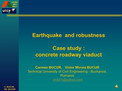
London2011WG 7Earthquake <strong>and</strong> robustnessCase study :concrete roadway viaductCarmen BUCUR, Victor Mircea BUCURTechnical University of Civil Engineering - Bucharest,<strong>Romania</strong>vmb51@yahoo.comC. BUCUR,VM. BUCUR
London2011WG 7The objectivesThree objectives1. About Robustness2. Seismic assessment in <strong>Romania</strong>3. Case studyC. BUCUR,VM. BUCUR
London2011WG 71. Robustness"What is" robustness?What do you think about when you say that something/someone is “robust”?A bull in its fullness <strong>and</strong> integrity of itsphysical strength …… or a millipede with its many legs <strong>and</strong> flexiblemovement?C. BUCUR,VM. BUCURTheoretically, redundant systems are believed to be more robust than nonredundant systems -but this is not always true in practice.Robustness is related to the scenarios of local damage of the structural system.
London2011WG 71. Robustness* In Eurocode EN 1991-1-7:2006 ”Robustness is defined like the ability of a structure to withst<strong>and</strong>events like fire, explosions, impact or the consequences of human error, without being damaged to an extentdisproportionate to the original cause”.* In the JCSS Probabilistic Model Code, the following robustness requirement was <strong>for</strong>mulated: “Astructure shall not be damaged by events like fire, explosions or consequences of human errors, deteriorationeffects, etc. to an extent disproportionate to the severeness of the triggering event”.* In COST-TU0601 papers - “A structure shall incorporate robustness through consideration of theeffects of all hazards <strong>and</strong> their probabilities of occurrence, to ensure that consequent damage is notdisproportionate to the cause. Damage from an event with a reasonable likelihood of occurrence shall not leadto complete loss of integrity of the structure. In such cases the structural integrity in the damaged state shall besufficient to allow a process system close down <strong>and</strong>/or a safe evacuation.”* In professor Uwe Starossek’s works “Robustness, is a desirable property of structural systemswhich mitigates their susceptibility to progressive disproportionate collapse. It is a property of the structurealone <strong>and</strong> independent of the possible causes <strong>and</strong> probabilities of the initial local failure.”C. BUCUR,VM. BUCURStarossek <strong>and</strong>Haberl<strong>and</strong> in 2010made this schema todefine the robustness
London2011WG 71. RobustnessDesign scenarios:Theoretically, the structure must be checkedin a „n” number of scenarios separately.Practically, the systems are checked in afinite number of design scenarios, chosen tobe realistic <strong>and</strong> representative <strong>for</strong> thepurpose of predicting the actual lifecycleper<strong>for</strong>mances of the system.Typical design scenarios are:(i)(ii)design scenarios <strong>for</strong> the intact structure;accidental design scenarios in whichthe initial state of the structurecorresponds to a damaged state.For <strong>Bridge</strong>s [COST tu0601 - Diamantidis D.(2011)]The requirement to avoid progressive collapse in caseof local failure is an important design criterion <strong>for</strong> multispanbridges. It can have strong impact on bothconceptual design, including choice of structuralsystem, <strong>and</strong> detailed design. Current design codes donot strictly require the prevention of progressivecollapse of bridges.C. BUCUR,VM. BUCURAmong the studied specializedtechnical literature, the most exhaustive set ofrecommendations was found in the paper GSA -Progressive Collapse Analysis <strong>and</strong> DesignGuidelines <strong>for</strong> New Federal Office Buildings <strong>and</strong>Major Modernization Projects - June 2003. Therecommendations are given <strong>for</strong> frame <strong>and</strong> shearwalls structures separately.Scenarios concerning the position ofthe removed resistance elementsThe restrictions proposed by thetechnical regulations <strong>for</strong> thedimensions of a damageconsidered as local.
London2011WG 71. RobustnessThe difference between the progressive collapse <strong>and</strong> the globalone is given by two characteristics:• its triggering by the failure of a relatively limited area <strong>and</strong>• the existence of a time lag until the total collapse.EVENTOne or few structuralelements failureCypress Viaduct „Loma Prieta” 1989Chile 2010Is it structuralcapacity to undertakeinitial failure’sconsequences?NoCOLLAPSEYesLoadsredistributeCollapsestopsFinal damage is outof proportion toinitial failure?NoC. BUCUR,VM. BUCURYesPROGRESSIVECOLLAPSECpllapse, butnot Progressive
London2011WG 72. Seismic assessment in <strong>Romania</strong><strong>Romania</strong> is highly vulnerable to earthquake<strong>and</strong> flood. It is one of the most seismicallyactive countries in Europe.United Nations,<strong>International</strong> Strategy<strong>for</strong> Disaster Reduction(The World Bank) –SOUTH EASTERNEUROPE DISASTERRISK MITIGATIONAND ADAPTATIONINITIATIVE - Geneva2002The strongest Vrancea earthquake ever occurred isaccepted to be the Oct 26, 1802 event (M = 7.5….7.7); the most disastrous event is March 4, 1977earthquake (M=7.2; Mw=7.4 …7.5).Vrancea subcustral (60-180 km) seismicsource in Carpatian Mountains of <strong>Romania</strong>[Lungu, et al, 2011]C. BUCUR,VM. BUCURAn advanced approach to earthquake riskscenarios with applications to different European towns -Map of seven towns involved in the RISK-UE Project,[Lungu et al, 2011]Seismicityof the Banatregion (M≥4.1)
London2011WG 72. Seismic assessment in <strong>Romania</strong>C. BUCUR,VM. BUCUR
London2011WG 73. Case studyThe study contains following research directions:1. How the use of a type or another of a finite element will influences the initial damage’smodelling.2. The effect of the initial failure type <strong>for</strong> the inherent dynamic response of the structure <strong>and</strong>,actually, what element <strong>for</strong> that answer – the value of the inherent period or the <strong>for</strong>m of theeigenvalue – is more susceptible <strong>for</strong> the initial type of failure.3. If from the previous study may be seen when one supplementary study about the structure’srobustness is necessary.4. If a well-made structure from the point of view of the seismic answer is enough robust atothers extreme loads – explosions, shocks, etc.The object of this study is a concrete roadway viaduct, with eight spans, <strong>for</strong> two traffic lanes.Having in view the height of the piers <strong>and</strong> the way the girders rest on them, we choose a section made outpiers P2, P3, P4 <strong>and</strong> the superstructure corresponding to the two spans.MODEL9.00 33.07 5 33.05 33.05 33.05 33.05 33.05 33.05 33.07 5 9.00GBHBHBGBHBGB HB GB GB HB HBGBGBHBHBGB1.3 1.3 1.306.3 6.030.630.636.2P1P5P6P7C. BUCUR,VM. BUCURP2P3P4
London2011WG 73. Case studyCalculation modelThe calculation model is three-dimensional one.The piers have lamellar elevations with H section on their upper part<strong>and</strong> right-angled section at their bottom lower part. Pile 3 has 31,90 m totalheight of which 30,60 m is the lamellar elevation <strong>and</strong> 1,30, the cross head.This pier was modelled using three-dimensional finite elements withdimensions chosen so that to follow closely the shape of the pier. The Pier2 <strong>and</strong> Pier 4 (the highest) as well as the superstructure girders aremodelled with one-dimensional elements of equivalent section.The over-concreting plate is modelled using bi-dimensional elements.Study scenariosThe scenarios proposed to remove somestructural elements are divided into twocategories:(i) initial damages at the piers level <strong>and</strong>(ii) initial damages at the superstructure level.C. BUCUR,VM. BUCUR
London2011WG 73. Case studyThis presentation focuses on the question: how the modelling of the same structure elementswith different types of finite elements may en<strong>for</strong>ce different approach <strong>for</strong> the modelling of theinitial failure.For the piers damages, we have proposed the following:(i) <strong>for</strong> the three piers, to trans<strong>for</strong>m some sections intohinges (above the right-angled area <strong>and</strong> at the levelof the cross head);(ii) <strong>for</strong> the pier P3 to remove part of the section.To take into consideration a damage of the type when a section of the pier changesinto a hinge, the question is how to model this hinge at the level of pier P3, which was modelledwith three-dimensional finite elements. For the three-dimensional elements, it is proposed tointroduce a new material with a different longitudinal elasticity module. The variation of thelongitudinal elasticity module was chosen to range between E:10 6 <strong>and</strong> E:4/3 - 11 cases areproposed .C. BUCUR,VM. BUCURFor the lateral piers – P2 <strong>and</strong> P4 - which are modelled with one-dimensional finiteelements, this scenario was easy to be modelled.
London2011WG 73. Case studyThe entire study is based on 38 scenarios of the removing some elements, in the following way:PIERSC1_low – hinge at the lower part of the pier with three-dimensional finite elements (P3) with the11 values cases <strong>for</strong> the longitudinal elasticity module: (a) soft; (b...h) medium; (i...k) strong;C2_upper – hinge at the upper part of the pier with three-dimensional finite elements (P3) withthe 11 values cases <strong>for</strong> the longitudinal elasticity module: (a) soft; (b...h) medium ;(i...k)strong;C3_hinge at the lower part of the left pier (P2);C4_hinge at the lower part of the right pier (P4);C5_hinge at the upper part of the left pier (P2);C6_hinge at the upper part of the left pier (P4);C7(a,b,c)_ 25%, 50% <strong>and</strong> 75% lacking from the lower part of the pier modelled with threedimensionalfinite elements (P3);C8(a,b,c)_ 25%, 50% <strong>and</strong> 75% lacking from the upper part of the pier modelled with threedimensionalfinite elements (P3);DECKC9(a,b,c)_ lacking from the deck supporting area with: one third laterally, one third in the centre,two thirds from the cross section;C10(a,b,c)_ lacking from the deck central area with: one third laterally, one third in the centre, twothirds from the cross section;-----------------------------------------------------To these scenarios the initial situation of the entire structure is added – marked C0.C. BUCUR,VM. BUCUR
London2011WG 73. Case studyResults. CommentsSome results of the study will be presented, those obtained <strong>for</strong> the scenarios corresponding toinitial damages at the piers level, based on their inherent dynamic response.From other studies carried out by the authors the conclusion was drawn that the ef<strong>for</strong>ts redistributionis made not necessarily to the elements adjacent to the removed one. Consequently, the structure behaviourshall be studied as a whole.The authors consider that the mechanical values of their inherent dynamic response being anessential characteristic of the structure characterizing its general behaviour, may also give in<strong>for</strong>mation on theway the progressive collapse phenomena may develop.a. C0-mode 1 b. C0-mode 2 c. C0-mode 3The first three modes of vibration <strong>for</strong> the case of the entire structureC. BUCUR,VM. BUCURThe first three modes ofvibration <strong>for</strong> the scenariowith a joint at the inferiorlevel of the pile modelledwith three-dimensionalfinite elementsC1e-medium 4(E1e=E:1000)
London2011WG 73. Case studyIn a first stage, it was intended to choose a value of the longitudinal elasticity module of thematerial modelling the hinge at the thre-dimentional pier, the value above or under which nothinginteresting from the engineering point of view, happens.The way the values of the inherent dynamic response were processed is under the <strong>for</strong>m of thevariation of the relative decrease of the values of the inherent periods calculated according tothe <strong>for</strong>mula:D relative = (T i – T i-1 ) / T i0,80,80,60,60,40,2Drel(1)Drel(2)Drel(3)0,40,2Drel(1)Drel(2)Drel(3)0C. BUCUR,VM. BUCURC1b C1c C1d C1e C1f C1g C1h C1i C1j C1k0C2b C2c C2d C2e C2f C2g C2h C2i C2j C2kVariation of the relative decreases (from one scenario to the next) of the eigenvalues calculated with <strong>for</strong>mula* A first conclusion is that <strong>for</strong> the longitudinal elasticity module cannot be chosenonly one value both <strong>for</strong> the scenario with a hinge at the lower part of the pier <strong>and</strong> <strong>for</strong>the scenario with a hinge at the upper part of the pier. To go on with the study thetwo scenarios were chosen where the response is the most different, namely: <strong>for</strong>the hinge at the lower part of the pier the scenario C1e (E1e=E:1000) <strong>and</strong> <strong>for</strong> thehinge at the upper part of the pier scenario C2d (E2d=E:10000).
London2011WG 73. Case study32,52Graphical representation of theeigenvalues of the first threemodes of vibration <strong>for</strong> thescenario - joints at both inferior<strong>and</strong> superior level1,510,50C0 C1e C3 C4 C725%For thefundamentalmode:C750%C7 C2d C5 C6 C875%25%C850%C875%T1 sT2 sT3 sThe inherent period of the fundamental module <strong>for</strong>the structure when it is complete show a flexiblebehaviour. Consequently, we considered asnecessary, at least <strong>for</strong> the study, the modules two<strong>and</strong> three as well.The periods of the fundamental module has higher values <strong>for</strong> the scenarios with a hinge at thelow part of the piers having a peak <strong>for</strong> the scenario C4-hinge at the low part of pier P4 (thehighest pier in the structure). The ratio of the fundamental periods C4/C0 is 2,04.For modetwo:For modethree:C. BUCUR,VM. BUCURThe diagram <strong>for</strong> the periods of the mode two show higher variations. There are two peakscorresponding to the scenarios <strong>for</strong> pier P4. The maximum ratio, which is also <strong>for</strong> the periodsC4/C0, this time is 1,71. In the same time, one can see that the periods’ values of the scenariosC1e <strong>and</strong> C7 are practically equal.The values of the specific periods are relatively constant. The scenarios having the highestperiods are C2d (the ratio of periods C2d/C0 is 1,44) <strong>and</strong> C1e.
London2011WG 73. Case studyC4-mode 1 C6-mode 1 C8c-mode 3Eigenvectors <strong>for</strong> various scenarios:C7b-mode 1 C7b-mode 2 C7b-mode 3The first three modes of vibration <strong>for</strong> the scenario C7b_lacks over 50%C. BUCUR,VM. BUCURWe consider being useful to carry out another study as well, in which to combine morescenarios, especially <strong>for</strong> the case where we try to determine the minimum damages that maylead to a controlled demolition.
London2011WG 7The concept of structural robustnessis based on intuitive underst<strong>and</strong>ingof structural resilience against propagation of damagecaused by local loss of structural resistance[CICHOCKI & RIZZUTO, 2011].C. BUCUR,VM. BUCUR
London2011WG 74. BIBLIOGRAPHY (selected)• Canisius G.T (editor), (2011) - STRUCTURAL ROBUSTNESS DESIGN FOR PRACTISING ENGINEERS - COST Action TU0601 –Robustness of Structures, V1.1, 1 June 2011, (website: www.costtu0601.ethz.ch)• Diamantidis D.(2011) - Robustness in Other Disciplines - STRUCTURAL ROBUSTNESS DESIGN FOR PRACTISINGENGINEERS - COST Action TU0601 – Robustness of Structures, V1.1, 1 June 2011, (website: www.costtu0601.ethz.ch)• Kwasniewski L., Izzuddin BA., Pereira M., <strong>Bucur</strong> C., Gizejowski M.,(2009) - MODELLING AND ANALYSIS - COST – BuildingEuropean Science – Proceedings of the Loin Workshop of COST Action TU0601 & E55 2009, pp. 91-102, ISSN 978-3-909386-29-1,Switzerl<strong>and</strong>/2010; site http://www.cost-tu0601.ethz.ch/* Starossek, U. <strong>and</strong> Haberl<strong>and</strong>, M. (2010) - DISPROPORTIONATE COLLAPSE: TERMINOLOGY AND PROCEDURES. Journal ofPer<strong>for</strong>mance of Constructed Facilities, 24(6):519-528.• Creţu D., Demetriu S., (2006) - METODE PENTRU CALCULUL RĂSPUNSULUI SEISMIC ÎN CODURILE ROMÂNEŞTI DEPROIECTARE. COMPARAŢII ŞI COMENTARII - Revista AICPS, Nr. 3/2006• Lungu D., Văcăreanu R., Arion C., Aldea A., (2011) - BUILDING INVENTORY DATA FOR SEISMIC RISK MITIGATION – NEROEuropean Building Inventory Workshop, Pavia 2011• Moldoveanu C.L., Radulian M., Mărmureanu Gh., Panza G.F. - OUTLINES OF SEISMIC MICROZONING OF BUCHAREST,ROMANIA - United Nations Educational Scientific <strong>and</strong> Cultural Organization <strong>and</strong> <strong>International</strong> Atomic Energy Agency, The ABDUSSALAM <strong>International</strong> Centre <strong>for</strong> Theoretical Physics, MIRAMARE – TRIESTE March 2002*** United Nations, <strong>International</strong> Strategy <strong>for</strong> Disaster Reduction (The World Bank) – SOUTH EASTERN EUROPE DISASTER RISKMITIGATION AND ADAPTATION INITIATIVE - Geneva 2002*** <strong>Romania</strong>n Technical RegulationsC. BUCUR,VM. BUCUR* <strong>Bucur</strong> C., <strong>Bucur</strong> V.M. (2009) – WHAT IS „PROGRESSIVE COLLAPSE” - Buletinul Ştiinţific bilingv _UTCB – anul LII -no.4/2009, pp. 5-14* <strong>Bucur</strong> C., Rus A., <strong>Bucur</strong> VM., Moise I. (2010) - SCENARIOUS FOR THE CHECKING FOR PROGRESSIVE COLLAPSE OFA DUAL SYSTEM REINFORCED CONCRETE BUILDING - Revue Roumaine des Sciences Technique – Série de MécaniqueAppliquée, ISSN:0035-4074, Tome 55, N o 2, pp.91-99 , Ed. Academiei Române. Bucarest, 2010, (www.imsar.ro)* <strong>Bucur</strong> C., Moise D. - THE SPECTRAL RESPONSE OF A RAILROAD BRIDGE WITH HIGH SKEW–ROMANIA –<strong>International</strong> Conf. on <strong>Bridge</strong>s / Croatia 2006, „<strong>Bridge</strong>s” Proceedings Secon HDGH2006: lucrarea 36/Sesiunea 2/pag. 375-382* Stanescu Th., A. Rus, H. Kober, S. Zamfir, C. <strong>Bucur</strong> - REHABILITATION OF THE METALLIC STRUCTURE FOR THEROOF IN BUCHAREST NORTH STATION – „Steel - A new <strong>and</strong> traditional material <strong>for</strong> building ICMS2006” – Proceedingspublished by Taylor & Francis/Balkema, Great Britain, pp.639-646