Thermal Gasification of Biomass Introduction
Thermal Gasification of Biomass Introduction
Thermal Gasification of Biomass Introduction

You also want an ePaper? Increase the reach of your titles
YUMPU automatically turns print PDFs into web optimized ePapers that Google loves.
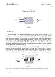
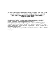
AustriaThere are two gasification demonstration projects in Austria: the first is at Zeltweg andthe second is two new plants which are being designed around the FICFB Process. Athird project, the bark gasification project at Pöls, is also described. <strong>Biomass</strong>gasification could become the second most important conversion process in Austria,especially for power production.Zeltweg BioCoComb ProjectIn a demonstration project supported by the EC ThermieProgramme a biomass gasifier for bark, wood chips,sawdust, etc has been installed at the 137 MW epulverised coal fired power station <strong>of</strong> Verbund-AustrianHydro Power AG in Zeltweg, Austria. The project title'BioCoComb' is an abbreviation for 'Preparation <strong>of</strong> Bi<strong>of</strong>uelfor Co-Combustion' where co-combustion meanscombustion together with coal in existing power plants.The gas produced substitutes approximately 3%(~ 10MW th ) <strong>of</strong> the coal fired in the boiler. The biomassfuel from plants is used in its raw form. Only the coarsefraction <strong>of</strong> the biomass has to pass a shredder and is thenfed together with the fine fraction into the gasifier. Partialgasification <strong>of</strong> the biomass is carried out at a temperature<strong>of</strong> 820°C, in a circulating fluidised bed reactor, whichmaintains uniform temperatures throughout the gasifier. Temperatures are low toprevent slagging. The low calorific value (LCV) gas produced is directly led via hot gasduct into an existing pulverised coal fired boiler for combustion. The carryover charfrom partial gasification passes through a cyclone separator and is fully combusted inthe coal boiler. The plant started its trial runs in November 1997 and has been insuccessful commercial operation since January 1998.Courtesy <strong>of</strong> Zeltweg BioCoComb Project, AustriaThe main advantages <strong>of</strong> the BioCoComb concept are:• drying <strong>of</strong> feed biomass is not required since the resulting LCV gas is acceptable forco-firing;• partial gasification <strong>of</strong> biomass results in a smaller gasifier;• no gas cleaning or cooling is required thus preventing tar condensationproblems;• the relatively low gasification temperatures prevents slagging;• there are favourable effects on power plant emissions (CO 2 , NOx);• there were no substantial modifications to the existing coal fired boiler;• there is high flexibility in arranging and integrating the main components intoexisting plants.5
New plants based on the FICFB ProcessAt present there are two FICFB Process plants in the detailed design stage. An 8MW th gasification plant will be located in Güssing, Burgenland and a 2 MW th plantwill be located in Wiener Neustadt, Niederösterreich. In the bigger plant a gas turbine,and in the smaller plant a gas engine will be used to produce electricity from the gas.The plant in Güssing will begin operation in summer 2000 and the smaller plant willcommence operation in winter 2000.The FICFB Process consists <strong>of</strong> a fluidised bed reactor divided into two zones, agasification zone and a combustion zone. The bed material is circulated between thesetwo zones while the gaseous products are kept separated. The circulating bed materialpromotes heat transfer between the combustion and the gasification zones. The fuel isfed into the gasification zone and gasified with steam. The gas produced in this zone istherefore nearly free <strong>of</strong> nitrogen. The bed material, together with some carryover char,circulates to the combustion zone. This zone is fluidised with air to burn the charparticles. The exothermic reaction in the combustion zone provides the energyfor the endothermic steam gasification zone. With this concept it ispossible to produce a medium calorific value product gas without the use<strong>of</strong> pure oxygen.Pöls Bark <strong>Gasification</strong> ProjectThe Pöls bark gasification project employing the Lurgi circulating fluidised bed (CFB)gasifier was built in 1987 in Pöls, Austria by a large paper mill, The plant wasdesigned to handle up to 6.6 TPH <strong>of</strong> dry bark, which is <strong>of</strong> approximately 35 MW thcapacity. Crushed and air dried bark is gasified in the air-blown CFB gasifier operatingat about 1 bar pressure. The resulting LCV fuel gas was to be partially cooled andfired in the paper mill’s lime kiln. However, because <strong>of</strong> the undesirable contamination<strong>of</strong> the lime with the ash contained in the fuel gas, the gasifier is not operatedcontinuously and it is now used for testing and evaluation purposes only.BrazilBrazilian BIG-GT Demonstration ProjectThe Brazilian Wood <strong>Biomass</strong> Integrated <strong>Gasification</strong>-Gas Turbine (BIG-GT)demonstration project, is to be located in the state <strong>of</strong> Bahia, in northeast Brazil. TheTPS low pressure, circulating fluidised bed (CFB) gasifier has been selected for theproject which is supported by the Brazilian Government, UNDP, the World Bank, andthe UN Global Environmental Facility. At present the project is being supported byMCT and a consortium made up <strong>of</strong> ELETROBRAS, and Companhia Hidro Eletrica doSao Francisco. The proposed 32 MW e project will use a GE LM2500 gas turbine. Adescription <strong>of</strong> the TPS process is given under some <strong>of</strong> the projects described below.6
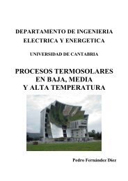
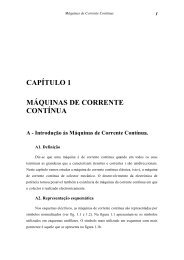
CanadaBIOSYN <strong>Gasification</strong> and Gas Conditioning TechnologiesThe BIOSYN gasification process was developed during the 1980s by BIOSYN Inc, asubsidiary <strong>of</strong> Nouveler Inc, and a division <strong>of</strong> Hydro-Quebec. The process is based on abubbling fluidised bed gasifier containing a bed <strong>of</strong> silica or alumina capable <strong>of</strong>operating up to 1.6 MPa. Extensive oxygen-blown biomass gasification tests wereconducted during 1984-88, in a 10 t/hour demonstration plant located at St-Juste deBretennieres, Québec, to produce synthesis gas for methanol production. Air blownatmospheric gasification tests were also conducted for evaluating cogeneration. TheBIOSYN process proved the technical feasibility <strong>of</strong> gasifying biomass from forest andagricultural residues. Subsequently, by using a 50 kg/h process development unit, theBIOSYN process has also proven the feasibility <strong>of</strong> gasifying primary sludges, refusederived fuel (RDF), rubber residues (containing 5-15% Kevlar), and granulatedpolyethylene and propylene residues.The process accepts feed particle sizes upto 5 cm, feed bulk densities higher than0.2 kg/l and feed moisture content up to20%. The thermal efficiency for biomassgasification varies from 70-80%. The fuelgas composition ranges from 30-55% N 2 ,16-30% CO 2 , 12-30% CO, and 2-10%H 2 . Air blown gasification produces 2Nm 3 fuel gas/kg <strong>of</strong> dry biomass. The gasyield reaches 4 Nm 3 <strong>of</strong> fuel gas/kg <strong>of</strong>polyethylene. With air as the gasifyingagent the higher heating value (HHV) <strong>of</strong> the fuel gas is about 6 MJ/Nm 3 . Enrichedair, with 40% oxygen, can produce a fuel gas having a HHV <strong>of</strong> about 12 MJ/Nm 3at half the gas yield. The raw gas cyclones remove 85-95% <strong>of</strong> entrainedparticulates.Courtesy <strong>of</strong> BIOSYNInc, CanadaThe supporting research and development includes gas scrubbing for efficient tarremoval with reduced water requirements, recycling the insoluble tars to the gasifier,wet oxidation and adsorption <strong>of</strong> dissolved organic compounds in the scrubbing water,and recycling carbon-rich ashes and carry over carbon with adsorbed organiccompounds to the gasifier. This effort also includes hot-gas filtration <strong>of</strong> entrained dustusing a static bed <strong>of</strong> perlite particles and a moving sand bed filter, and catalytic steamcracking <strong>of</strong> tar. Proprietary catalysts can decompose 99% <strong>of</strong> tars and 97% <strong>of</strong>naphthalene compounds. The BIOSYN technology is commercialized by EnerkemTechnologies Inc, a subsidiary <strong>of</strong> the Kemestrie Group, a spin-<strong>of</strong>f company <strong>of</strong> theUniversity <strong>of</strong> Sherbrooke. A commercial installation to gasify 2.2 t/hour <strong>of</strong> granulatedpolypropylene residues is now under construction in Spain. The electricity output will besold to the grid. Environmental International Engineering SL, a Spanish-baseddevelopment and engineering group, in partnership with Enerkem, will erect andcommission the plant in late 2000.7
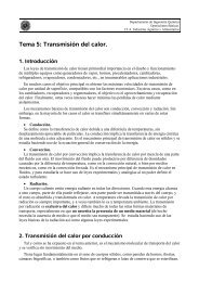
DenmarkHarboøre ProjectBetween 1988 and 1992, the Danish boilermanufacturer Ansaldo Vølund Energy choseto build an updraft, counter current, movingbed gasifier for the Harboøre DistrictHeating Project located on the west coast <strong>of</strong>Jutland. The updraft gasifier was selected tocircumvent feed drying, to achieve 99% carbon conversion, and to produce a highheating value fuel gas with low dust content. The Vølund gasifier is based on aGerman design and it is now operated with woody biomass, at 4 MW th capacity, toprovide heat to about 550 homes. The raw gas containing condensible tar and otherorganic compounds is cooled and scrubbed to separate and recycle these combustiblecondensates back to the gasifier. Extensive research and technology development wasconducted in support <strong>of</strong> this facility to test novel heat exchangers, tar crackingschemes, minimization and disposal <strong>of</strong> emissions and effluents, and operation <strong>of</strong> ICengines. The gasifier could be operated at higher capacity in the future forcogeneration applications. In January 2000, two 1.5 MW e gas engines were installedto cogenerate electricity and district heat.Courtesy <strong>of</strong> Voeland Research Centre, DenmarkHøgild ProjectThis 0.5 MW th capacity CHP project supplying heatand power for 120 homes and residences in Høgild nearHerning, started with the French Martezo co-currentdowndraft moving bed gasifier. The project owner HerningMunicipality, contracted the Hollesen Engineering Company toreconstruct the gasifier. Since December 1998, the gasifier has beenoperating satisfactorily. The feed stock for gasification is double screeneddry wood residues (15% or less moisture content) and waste fromwoodworking factories. The raw gas from the gasifier is cooled andcleaned using a wet scrubber, a sawdust filter, and a filter type waterseparator. The fuel gas with a lower heating value <strong>of</strong> 4-4.8 MJ/Nm 3 isburnt and consumed in a Mercedes gas engine to produce heat and power.The efficiency <strong>of</strong> electricity production is about 24%.Blære ProjectThe Department <strong>of</strong> Energy Engineering at the Technical University <strong>of</strong> Denmark (DTU)has developed a two-stage gasification process. Based on this technology a cogenerationplant producing 250 kW th and 100 kW e was built at Blære, Aars by the Danish REKAMaskinfabrikken company. Wood or straw is pyrolysed in a first stage screw-conveyedreactor by external heating at 600°C. The resulting volatiles react with preheatedair/steam mixture to produce a low-tar-containing fuel gas which is used to gasify the8
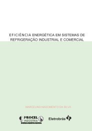
esidual char from the pyrolysis step. The resulting fuel gas is cooled and cleaned in aventuri scrubber and is fed to a 12 litre Perkins engine rated at 100-120 kW e . Thewaste heat from the engine exhaust is used to heat the first stage pyrolysis reactor. Theefficiency <strong>of</strong> electricity production is estimated to be 25%. Tests in the 50 kW th DTUPilot Plant showed that if the feed is dried to 30-35% moisture content the processmay consume the entire condensate and there may not be any need to provide a wastewater treatment facility. The pilot plant tests produced a fuel gas with a heating value<strong>of</strong> 6 MJ/Nm 3 at a thermal efficiency <strong>of</strong> about 90%.FinlandLahti Kymijärvi ProjectIn 1997-98, the Lahden LÄMPÖVOIMA Oy, installed a 60 MW th capacity atmosphericpressure Foster Wheeler (formerly Ahlström) CFB biomass gasifier, at a cost <strong>of</strong>approximately US$15 million at its 200 MW e fossil fuel fired power station. Thispower plant was originally built in 1976 to use fuel oil. In 1986 the burners in theboiler were converted to natural gas and a natural gas turbine cycle was added. Thebiomass gasification plant was installed primarily to use locally available fuels andwaste materials including plastics. The gasifier is a single gasifier vessel with a cycloneand an air preheater for heating the gasification air to approximately 400°C. The LCVgas is cooled from approximately 830-850°C to 700°C before it is transported in apipeline to the boiler. The raw gas has no adverse effecton the performance <strong>of</strong> the boiler. Emissions are reducedand the heating surfaces in the boiler stay relativelyclean. The reported gas composition (in volume %) is:12.9% CO 2 ; 4.6% CO; 5.9% H 2 ; 40.2% N 2 ; 33.0%H 2 O; 3.4% C x H y . The heating value <strong>of</strong> the LCV gas isapproximately 2.0-2.5 MJ/Nm 3 . The NOx emissionswere reduced by 5% (permitted level is 230 mg/MJ forboth NOx and SO 2 ) and the dust emissions werereduced by half because <strong>of</strong> increased conductivity <strong>of</strong>dust. However HCl emission increased by a smallquantity <strong>of</strong> 5 mg/Nm 3 . The present breakdown <strong>of</strong> fuelsin the boiler is approximately: 11% LCV fuel gas fromthe gasifier, 69% coal, 15% natural gas to boiler, and5% natural gas to gas turbine. The annual average totalefficiency is approximately 80%, the fuel to powerefficiency with gas turbine in operation is 35%. The gasturbine has increased the efficiency by 4% points. Theplant supplies 200 MW e power to the national grid(110 kV line round the town) and 250 MW th heat tothe town (100,000 inhabitants) and surrounding houses(main pipe 700 mm). The district heating system wasconstructed in 1958.Courtesy <strong>of</strong> Lahti Kymijärvi Project, Finland9
BIONEER ProcessCourtesy <strong>of</strong> BioneerKauhojoki, FinlandThe BIONEER gasifier is an updraft moving bed gasifier, producing tarry LCV fuel gas.The gasifier consists <strong>of</strong> a refractory lined vessel with a rotating cone-shaped grate.<strong>Biomass</strong> fuel is fed from the top, from where it flows downwards through drying,pyrolysis, gasification and combustion zones. The residual ash is discharged from thebottom by the rotating grate. The temperature <strong>of</strong> the combustion zone is regulated byhumidifying gasification air. Air and steam are fed as the gasification media throughthe grate. Since updraft gasification produces a raw gas with significant amounts <strong>of</strong>tar, the gas cannot be either transported long distances or directly used in IC engines.In the existing BIONEER plants the gas is burnt in a close coupled boiler to generatesteam and hot water for district heating. During the mid 80s, VTT and BIONEERconducted extensive tests with a variety <strong>of</strong> feed stocks (eg wood chips, forest wastes,peat, straw, RDF pellets, and coal and RDF mixed with wood chips) in a 1.5 MW thpilot plant located at BIONEER’s Hämeenlina works. A typical gas composition with41% moisture content wood chips consists <strong>of</strong> 30% CO, 11% H 2 , 3% CH 4 , 7% CO 2 ,and 49% N 2 , with a HHV <strong>of</strong> 6.2 MJ/Nm 3 . The tar content <strong>of</strong> dry product gas isestimated to be in the range <strong>of</strong> 50-100g/Nm 3 . Between 1985 and 1986, whenfuel oil prices were high, eightcommercial BIONEER plants, withcapacities ranging from 4-5 MW th , werecommissioned, five in Finland and three inSweden. Four plants are operated withwood or wood and peat mixtures while therest are operated with peat only. Most <strong>of</strong>the gasifiers are in operation at smalldistrict heating plants to providecirculating hot water. The BIONEERplants are completely automated andoperated with minimal personnel costs.Ahlstrom Corporation bought the BIONEER company originally owned by YITCorporation. After Foster Wheeler acquired Ahlstrom, a 6.4 MW th plant was installedat Ilomantsi, in eastern Finland in 1996. The estimated investment cost for districtheating applications is about 350 kECU/MW th and the operating cost is about 17ECU/MWh.Wisa Forest Pyr<strong>of</strong>low Gasifier10In 1981, Ahlstrom Corporation developed the first 3 MW th capacity pilot CFB gasifierfrom its successful CFB pyr<strong>of</strong>low combustion technology at the Hans AhlstromLaboratory at Karhula. The first commercial Ahlstrom Pyr<strong>of</strong>low CFB gasifier wascommissioned in 1983 at the Wisa Forest Pulp and Paper Mill in Pietarsaari, Finland.The fuel for the 35 MW th (about 150 t/day <strong>of</strong> biomass) gasifier is primarily bark andsawdust, sized up to 5cm, and dried at 150°C to about 15% moisture content. Thebiomass is fed from the side into the circulating sand <strong>of</strong> an air-blown CFB gasifiermaintained at about 900°C. The hot fuel gas at 700°C, is fed directly to a lime kiln.The objective <strong>of</strong> replacing 85% <strong>of</strong> the fuel oil for the lime kiln was achieved within a
few months <strong>of</strong> start up. Between 1985 and 1986, three more gasifiers, two in Sweden(25 MWth at Norrsundet Bruks, AB, Norrsundet and 27 MW th at ASSI, KarlsborgBruk, Karlsborg) and one in Portugal (15 MW th at Portucel, Rodao Mill), were builtand commissioned for firing lime kilns.ItalyThermie Energy Farm ProjectThe Thermie Energy Farm (TEF) Project byBioelettrica SpA employing the atmospheric LurgiCFB-gasifier is now under construction at Cascina,near Pisa. The 43 MW th capacity plant will produceabout 14 MW e . The air-blown gasifier will gasify upto 3.5 cm biomass feedstocks (poplar and Robiniawood chips, olive residues, grape residues, andsawdust) with about 5% moisture (after drying at theplant by the flue gases from the heat-recovery steamgenerator) at a temperature <strong>of</strong> about 800°C and 1.5bar(a) pressure. The raw LCV fuel gas is cleaned <strong>of</strong>most particulates in cyclones, cooled, scrubbed, andcompressed prior to producing electricity in a gasturbine and heat-recovery steam generation and steamturbine plant. The project is owned by Bioelettrica SpA,whose shareholders are USF Italia, Electricidade de Portugal-EDP, Lurgi, EnergiaVerde, and Fumagalli, and receives financial contribution from the EC under theThermie 1994 programme. The plant is expected tobe operational in the middle <strong>of</strong> 2002.Courtesy <strong>of</strong> Bioelettrica, ItalySAFI SpA RDF <strong>Gasification</strong> ProjectThe first commercial TPS CFB gasification processwas built for RDF gasification at Loc Testi, Passodei Pecorai, Greve in Chianti. RDF pellets, up to150 mm long, are fed into the lower section <strong>of</strong> a15 MW th capacity CFB gasifier, at a rate <strong>of</strong> about3 t/hour. The TPS gasifier operates at low (2500mm water) pressure and a temperature <strong>of</strong> about875°C, employing air as the gasification/fluidizingagent. Part <strong>of</strong> the air is injected at the bottom <strong>of</strong>the gasifier and the remainder is injected part wayup the vessel. This pattern <strong>of</strong> air distributioncreates a high-density bed in the lower part <strong>of</strong> thevessel, which allows the gasifier to handle relativelylarge-sized fuel particles. The CFB <strong>of</strong> sandparticles are maintained by a superficial gasvelocity <strong>of</strong> about 3-10 m/s.Courtesy <strong>of</strong> SAFI SpA <strong>Gasification</strong> Project, Italy11
The pellets are gasified within the 2-2.2 seconds residence time producing an LCV fuelgas <strong>of</strong> about 8 MJ/Nm 3 . The raw gas passes through two stages <strong>of</strong> solids separationbefore being fed to a furnace/boiler to generate steam for producing 6.7 MW e in acondensing steam turbine. The overall power generation efficiency is about 19-20%.Alternatively, part <strong>of</strong> the raw gas can be fired in a nearby cement kiln. The flue gasexiting the boiler is cleaned in a three-stage Research Cottrell scrubber before ventingthrough the stack. The plant has been operated intermittently due to difficulty inobtaining a continuous supply <strong>of</strong> RDF pellets.The NetherlandsKARA/BTG Co-current Downdraft Gasifier SystemThis 150 kW e system incorporates two special features:• The use <strong>of</strong> a low-speed (750 rpm), low-cost, robust engine made in China. Thismarine diesel engine is re-designed for use in connection with rice husk gasifiers. Theengine is less sensitive to impurities and its efficiency is lower than modern, lean-burnengines. Any loss due to the low engine efficiency is compensated by incorporation <strong>of</strong>a roots blower to compress the fuel gas to enhance its volumetric heating value.• The fuel gas enters the engine at a temperature higher than thedew-point, thus avoiding any condensation.The system consists <strong>of</strong> a fuel feeding conveyor, gasifier, two cyclones, baffle filter, gascooler, bag-house filter, roots blower, and gas engine.The gasifier feed is either sized orbriquetted block-sized wood. The fuel gas has a heating value <strong>of</strong> about 4.5 MJ/Nm 3 ,with tar and dust content below 100 mg/Nm 3 .A demonstration plant is scheduled for early 2000 at abriquetting plant near KARA. Power will be delivered to the grid whilethe heat will be used for the drying system <strong>of</strong> the briquetting plant. Thedevelopers include a consortium <strong>of</strong> KARA Energy Systems BV, BTGbiomass technology group BV and CPS, CompackSys BV, with fundingsupport from Shell International Renewables and Novem.Stork Thermeq Co-current Downdraft <strong>Gasification</strong> SystemThis 400 kW e system consists <strong>of</strong> a double valve fuel feeder, a gasifier developed atEnergy Research Centre Netherlands (ECN), thermal catalytic tar cracker developedand patented by BTG, and an IC engine for producing electricity. A 400 kW edemonstration plant will be constructed during 2000 in Goor. The gasifier will befed partly with composted waste wood. The electricity will be supplied to the grid andsold to Essent as 'green' power and the heat will be used in the greenhouses in Goor.The main objective is to demonstrate and validate the technology for subsequent scaleupto a commercially viable, fully automated, turnkey biomass gasification installationproducing 2 MW electrical and 4 MW thermal power. The developers include aconsortium <strong>of</strong> Stork Thermeq, BTG and KARA.12
Amergas BV ProjectThis 30 MW e project is under construction at the Amerpowerstation at Geertruidenberg in southern Holland, togasify low quality demolition wood (about 150,000 TPY)which cannot be recycled by the chipboard industry. Thegasifier is an 83 MW th low-pressure, Lurgi CFB gasifier.The product gas will be cooled for steam recovery, scrubbedto remove particulates and ammonia and burnt in the coalfired Amer 9 cogeneration unit. The unit has a netproduction capacity <strong>of</strong> 600 MW e and 350 MW th . The startup <strong>of</strong> the plant is planned for early 2000.NorwayCourtesy <strong>of</strong> NOVEM,The NetherlandsAt present there are no demonstration or commercial biomass gasification projects inNorway. Potential applications for gasification may be to improve pulp and paper milloperations and for cogeneration in remote sites.SwedenGotaverken Project (Varo)The Gotaverken (Kvaerner) process employs a CFB gasification process developed in a2 MW th pilot plant at the Royal Institute <strong>of</strong> Technology. Sized and dried fuel is fed afew meters above the bottom <strong>of</strong> the gasifier to create two distinct zones. In the upperzone, biomass is flash pyrolyzed by coming in contact with hot circulating dolomite, ata temperature <strong>of</strong> 645°C, and produces fuel gas rich in C 2 + and some tars. In the lowerzone the recycled residual char is combusted with air to produce the hot flue gases thatpromote flash pyrolysis in the upper zone. The circulating bed <strong>of</strong> dolomite promotes tarcracking and reduces the amount <strong>of</strong> heavy hydrocarbons produced in the gasifier.The LCV fuel gas is partially cooled in a heat exchanger to preheatgasification air and then burnt in a lime kiln. The plant start up was in1987 and turned over to the customer in 1988. A typical gascomposition is 15% CO, 10% H 2 , 5% CH 4 , 3% C 2 +, 16% CO 2 , 8%H 2 O, and 43% N 2 . Gotaverken has not built any more such biomassgasification plants due to low oil prices.13
Värnamo ProjectThis is the first demonstration <strong>of</strong> the pressurized Foster Wheeler-Ahlstrom CFB biomassCourtesy <strong>of</strong>Sydkraft, Swedengasification process, operating at 20 bar pressure and 950-1000°C. The 18 MW thcapacity IGCC demonstration cogeneration plant uses a feed stock consisting <strong>of</strong> 40%wood chips and 60% bark. The hot-gas filter employs high temperature ceramicSchumacher candle filters. The gas composition (in volume %) is reported as 10-12%H 2 ; 15.5-17.5% CO; 5-7% CH 4 ; 14-17% CO 2 ; 45-50% N 2 . The fuel gas heating valueis 5-6 MJ/Nm 3 (dry gas); tars
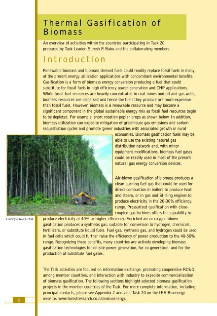
SwitzerlandPyr<strong>of</strong>orce <strong>Gasification</strong> PlantA commercial 200 kW e Pyr<strong>of</strong>orce gasifier with a Jenbacher engine is currently underconstruction at a military research center near Interlaken. The plant employs aPyr<strong>of</strong>orce gasifier, based on the KHD (Kloeckner Humbolt Deutz) high temperaturegasification process and a dry gas clean up system. The downdraft moving bed gasifiermaintains a temperature <strong>of</strong> 1200-1300°C in the combustion zone. Plantcommissioning is scheduled for the middle <strong>of</strong> 2000. Although pilot tests wereconducted with demolition wood, uncontaminated wood chips will be used as thegasification feed material.Courtesy <strong>of</strong> IISc, SwitzerlandIndian Institute <strong>of</strong> Science-DASAGGasifierThe Indian Institute <strong>of</strong> Science (IISc)-DASAGgasifier is an air-blown, low pressure, open-top, cocurrent,downdraft, moving bed system with aspecially designed lateral air inlet to reduce tarproduction. The gasification feed material isuncontaminated woody biomass materials. A pilot demonstration plantdesigned for 330 kW th and 100 kW e capacity is in operation at Châtel-St-Denis. Theplant is equipped with a Swiss gas cleaning system and a 6 cylinder Liebherr gasengine. The present electrical output is 55 kW e . Theelectrical efficiency <strong>of</strong> the plant (from wood to electricity)is 24%. The plant had operated for about 700 hours byNovember 1999. Continuous tests lasting up to 1500hours are expected to be complete by February 2000. Airblowngasification tests with biomass feed up to 8 cm inparticle size, produced a gas composition with 18% CO,13% CO 2 , 2% CH 4 , 18% H 2 , 15% H 2 O, 34% N 2 , 50mg/Nm 3 tar, and 700 mg/Nm 3 particulates.Courtesy <strong>of</strong> IISc, SwitzerlandUnited KingdomARBRE ProjectThe ARBRE project employs the low pressure TPS gasifier.The 8 MW e capacity plant is currently under construction inYorkshire. The project integrates the use <strong>of</strong> Yorkshire’s municipal sludgefor growing short rotation coppice plants for biomass gasification and includesrecycling the gasifier ash back to the coppice plantations as a soil conditioner. Thebiomass feed stock is derived from 2000 hectares <strong>of</strong> willow and poplar short rotationCourtesy <strong>of</strong> ARBRE Energy Ltd, UK15
coppice plantation. The air-blown TPS gasifier is close coupled to a CFB catalytic tarcracker to reduce tar in the LCV gas which is cooled and water scrubbed to producea clean fuel gas. The fuel gas is compressed and combusted in a gas turbine heatrecovery steam generation system to produce 8 MW e employing a Typhoon EuropeanGas Turbine. The projected overall electrical efficiency is 31%. Initial shakedown andstartup <strong>of</strong> the gasifier is scheduled for early 2000. The project team consists <strong>of</strong>Yorkshire water, TPS, and AEP, part <strong>of</strong> Compagnie Generale des Eaux <strong>of</strong> France, whowill provide operating and maintenance services.Boughton Pumping Station CHP ProjectThis is the second installation by Rural Generation Ltd, the company that developedUK's first on-farm CHP biomass-fuelled plant inLondonderry. The new plant produces 100 kW eand approximately 180 kW <strong>of</strong> heat. The plantincludes a downdraft, moving bed gasifier basedon the concept <strong>of</strong> Pr<strong>of</strong>essor J. Martins <strong>of</strong> theUniversity <strong>of</strong> Louvain in Belgium. The power isproduced by a six cylinder, dual fuel, Ivecoengine running on 80% wood and 20% diesel -although eventually it will run on 10% diesel.The ex-works price for such a unit, includingthe gasifier, gas clean-up system, engine andgenerator, and heat recovery unit, is about£80,000. However, local factors can influence the cost significantly.The unit produces heat and electricity for a converted water pumping station inOllerton, Nottinghamshire. The station was originally built in 1905, to house the steamoperated pumps that supplied the city <strong>of</strong> Nottingham. It is now used as a workshop and<strong>of</strong>fice complex, with restaurant and conference facilities. The basement houses apopular 'hands on' sustainable energy exhibition. The project does not have a NFFOcontract, although the plant puts electricity into the local grid at peak-price times <strong>of</strong>day, like its forerunner in Londonderry.Courtesy <strong>of</strong> Rural Generation Ltd, UKBlackwater Valley Museum Project16B9 Energy <strong>Biomass</strong> Ltd, undertook this project in 1995 to develop and operate awood fuelled, combined heat and power unit to provide heating and clean electricityfor 400 homes. The project team consists <strong>of</strong> B9 <strong>Biomass</strong>, ArmaghCity and District Council and the Blackwater Valley Museum,Benburb. The fuel used will be a mixture <strong>of</strong> wood from existingforests and coppiced willow from local farmers. However, to beginwith, until grants are in place to encourage farmers to grow willow,the unit will use sawmill wood chips. The plant uses a downdraft,moving bed gasifier linked to a reciprocating engine to producearound 400 kW <strong>of</strong> heat and 200 kW <strong>of</strong> electricity at 415 volts.This is transformed to 11kV and carried away on the NIE grid.The plant is capable <strong>of</strong> 24 hours per day unmanned operation for aCourtesy <strong>of</strong> B9 Energy <strong>Biomass</strong> Ltd, UK
MTCI ProcessThe MTCI gasification process also employs indirect heating to promote steamgasification <strong>of</strong> biomass to produce a MCV fuel gas. The gasifier combusts part <strong>of</strong> thefuel gas in pulsed combustion burners which promote heat transfer to the gasificationsection. Extensive pilot plant tests were conducted in a 20 t/day process developmentunit (PDU) at MTCI laboratories near Baltimore, Maryland. These tests also includedan evaluation <strong>of</strong> black liquor gasification. Based on the PDU tests a 50 t/daycapacity black liquor gasification demonstration unit was built at Weyerhaeuser’sNew Bern facility. The MTCI process group is currently designing and building amodular system and also seeking partnerships and support to demonstrate othergasification applications.IGT RENUGAS ProcessThe IGT RENUGAS process employs a 20 bar pressurized bubbling fluidised bedprocess. The process was extensively tested with a variety <strong>of</strong> biomass materials,including bark-sludge mixtures, bagasse, and pelletized alfalfa stems in a 12 t/dayprocess development unit (PDU) at IGT test facilities in Chicago. Subsequently USDOEselected the IGT process for scale-up and demonstration, using bagasse, at the HC&Ssugar mill at Paia in Hawaii. Since this 100 t/day demonstration plant had limitedsuccess in handling the low-density, shredded bagasse, the project was terminated. Atypical gas composition obtained in the IGT PDU with bagasse at 2.24 MPa, and 850°Cis 19% H 2 ; 26% CO; 37% CO 2 ; 17% CH 4 and 1% C 2 +. The heating value <strong>of</strong> this fuelgas is approximately 13 MJ/Nm 3 . The project participants included: US DOE <strong>Biomass</strong>Power Program, IGT, Westinghouse Electric Corporation, State <strong>of</strong> Hawaii, PICHTR,and HC&S.18Courtesy <strong>of</strong> Institute <strong>of</strong> Gas Technology, USA
The pressurized RENUGAS process coupled with hot-gas particulate and alkali cleanupis ideally suited for IGCC applications and to generate electricity at efficiencies in the40-42% range. IGT is currently seeking partnerships and support for furtherdemonstration <strong>of</strong> the RENUGAS process.Small Modular Biopower ProjectsThe objective <strong>of</strong> this program, sponsored and managed by DOE, NREL, and SNL, is todevelop small modular biopower projects that are fuel flexible, efficient, simple tooperate, have minimum negative impacts on the environment, provide power in the 5kW - 5 MW range, and are useful for domestic and international markets. The tenprojects selected for the Phase 1: Feasibility Studies are given below:Company Technology Size, kW eAgrilectric Fluid-bed Combustor/Steam Turbine 500-5000Bechtel Gasifier/Engines/Gas Turbine 500-1500Bioten Direct-fired Combustion Turbine 5000Carbona <strong>Gasification</strong>/Steam Turbine 1000-3000CPC <strong>Gasification</strong>/IC Engine 10-25EERC FBC/Steam Turbine 500-5000NIMO <strong>Gasification</strong>/IC Engine/Gas Turbine 500-5000Reflective Energies <strong>Gasification</strong>/Gas Turbine 100-1000STM <strong>Gasification</strong>/Stirling Engine 25-70SunPower <strong>Gasification</strong>/Stirling Engine 1-10These projects are under evaluation to provide funds for Phase 2: Prototype Testing andPhase 3: Integrated Systems Demonstration.Brightstar SynfuelsBrightstar Synfuels, Houston, Texas and Baton Rouge, Louisiana, employs a modular,skid-mounted, tubular entrained-flow steam gasification system. The estimated cold-gasefficiency with 40% moisture feed is about 80%, with no tar formation. Three 1.5 MWunits are planned for East Texas, for natural gas replacement, and there is a potentialproject to couple the gasifier with an IC engine in Australia.19
<strong>Thermal</strong> Technologies<strong>Thermal</strong> Technologies, Inc. Camp Lejune, North Carolina employs a downdraftgasifier, operating at a maximum temperature <strong>of</strong> 982°C. Extensive tests wereconducted in a 816 kg/hr pilot unit with 10% moisture feed. The resulting 0.49Nm 3 /sfuel gas at 6.35 MJ/Nm 3 is fed to a Waukasha L7042 turbo-charged engine/generatorto produce 700 kW e .PrimenergyPrimenergy, Tulsa, Oklahoma employs an updraft gasifier in a 36 t/day capacity pilotunit. Sixteen different feed stocks have been tested, including switch grass, paper millsludge, rice straw, bagasse, and poultry litter. So far sixteen commercial units rangingin size from 50-550 t/day <strong>of</strong> rice husk have been installed to produce heat (for hot airor steam) or electricity (up to 12 MW). A 600 t/day capacity rice husk gasificationplant is now under construction at Riceland Foods, Stuttgart, Arkansas for producing15 MW e using an extraction steam turbine and a 150 t/day capacity rice huskgasification plant is under construction at Riceland Foods, Jonesboro, Arkansas coupledto a 7 t/hour steam boiler and three parboiled rice dryers.CratechCratech, Tahoka, Texas employs an air-blown, high pressure gasifier. A 2.2 t/hourcapacity unit coupled to a 225 kW Solar Spartan Turbine is now under construction.20