

saudi arabia-the largest telephone project in the world a new ...
saudi arabia-the largest telephone project in the world a new ...
saudi arabia-the largest telephone project in the world a new ...
- No tags were found...

You also want an ePaper? Increase the reach of your titles
YUMPU automatically turns print PDFs into web optimized ePapers that Google loves.
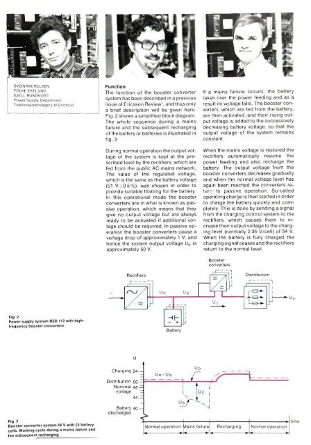
SVEIN MICHELSENFOLKE EKELUNDKJELLRUNDKVISTPower Supply DepartmentTelefonaktiebolaget LM EricssonFunctionThe function of <strong>the</strong> booster convertersystem has been described <strong>in</strong> a previousissue of Ericsson Review 1 , and thus onlya brief description will be given here.Fig. 2 shows a simplified block diagram.The whole sequence dur<strong>in</strong>g a ma<strong>in</strong>sfailure and <strong>the</strong> subsequent recharg<strong>in</strong>gof <strong>the</strong> battery or batteries is illustrated <strong>in</strong>fig. 3.Dur<strong>in</strong>g normal operation <strong>the</strong> output voltageof <strong>the</strong> system is kept at <strong>the</strong> prescribedlevel by <strong>the</strong> rectifiers, which arefed from <strong>the</strong> public AC ma<strong>in</strong>s network.The value of <strong>the</strong> regulated voltage,which is <strong>the</strong> same as <strong>the</strong> battery voltage(51 V±0.5%), was chosen <strong>in</strong> order toprovide suitable float<strong>in</strong>g for <strong>the</strong> battery.In this operational mode <strong>the</strong> boosterconverters are <strong>in</strong> what is known as passiveoperation, which means that <strong>the</strong>ygive no output voltage but are alwaysready to be activated if additional voltageshould be required. In passive operation<strong>the</strong> booster converters cause avoltage drop of approximately 1 V, andhence <strong>the</strong> system output voltage U D isapproximately 50 V.If a ma<strong>in</strong>s failure occurs, <strong>the</strong> batterytakes over <strong>the</strong> power feed<strong>in</strong>g and as aresult its voltage falls. The booster converters,which are fed from <strong>the</strong> battery,are <strong>the</strong>n activated, and <strong>the</strong>ir ris<strong>in</strong>g outputvoltage is added to <strong>the</strong> successivelydecreas<strong>in</strong>g battery voltage, so that <strong>the</strong>output voltage of <strong>the</strong> system rema<strong>in</strong>sconstant.When <strong>the</strong> ma<strong>in</strong>s voltage is restored <strong>the</strong>rectifiers automatically resume <strong>the</strong>power feed<strong>in</strong>g and also recharge <strong>the</strong>battery. The output voltage from <strong>the</strong>booster converters decreases graduallyand when <strong>the</strong> normal voltage level hasaga<strong>in</strong> been reached <strong>the</strong> converters returnto passive operation. So-calledoperat<strong>in</strong>g charge is <strong>the</strong>n started <strong>in</strong> orderto charge <strong>the</strong> battery quickly and completely.This is done by send<strong>in</strong>g a signalfrom <strong>the</strong> charg<strong>in</strong>g control system to <strong>the</strong>rectifiers, which causes <strong>the</strong>m to <strong>in</strong>crease<strong>the</strong>ir output voltage to <strong>the</strong> charg<strong>in</strong>glevel (normally 2.35 V/cell) of 54 V.When <strong>the</strong> battery is fully charged <strong>the</strong>charg<strong>in</strong>g signal ceases and <strong>the</strong> rectifiersreturn to <strong>the</strong> normal level.Fig. 2Power supply system BZD 112 with highfrequencybooster convertersFig. 3Booster converter system 48 V with 23 batterycells. Work<strong>in</strong>g cycle dur<strong>in</strong>g a ma<strong>in</strong>s failure and<strong>the</strong> subsequent recharg<strong>in</strong>g


