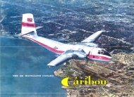
CREW MEMBER'S - The C-7A Caribou Association
CREW MEMBER'S - The C-7A Caribou Association
CREW MEMBER'S - The C-7A Caribou Association

You also want an ePaper? Increase the reach of your titles
YUMPU automatically turns print PDFs into web optimized ePapers that Google loves.
T.O. 1C-<strong>7A</strong>-1CL-1PILOTS'&<strong>CREW</strong> <strong>MEMBER'S</strong>ABBREVIATEDFLIGHT <strong>CREW</strong> CHECKLISTUSAF SERIESC-<strong>7A</strong>AIRCRAFTEach transmittal of this document outside of the Department ofDefense must have approval of the Technical Order DistributionControl Activity. Refer to T.O. 00-5-2.This manual supersedes T.O. 1C-<strong>7A</strong>-1CL-1 dated 3October 1967, changed 2 December 1969.COMMANDERS ARE RESPONSIBLE FOR BRINGINGTHIS CHECKLIST TO THE ATTENTION OF ALLPERSONNEL CLEARED FOR OPERATION OF THEAIRCRAFT.Published under authority of the Secretary of the Air Force.AFLC RAFB. GA 1 OCTOBER 1970
T.O.1C-<strong>7A</strong>-1CL-1Reproduction for nonmilitary use of the information or illustrationscontained in this publication is not permitted without specific approvalof the issuing service. <strong>The</strong> policy for use of Classified Publications isestablished for the Air Force in AFR 205-1.Technical orders are normally distributed promptly after printing. Date(s) shown on the title page (lower right) are for identification only. Thisis not a distribution date. Processing time sometimes causes distributionto only appear to have been delayed.INSERT LATEST CHANGED PAGES, DESTROY SUPERSEDED PAGES.LIST OF EFFECTIVE PAGES }~--------.NOTE : <strong>The</strong> portion of the text affected by the changes is indicatedby a vertical line in the outer margins of the page.Dates of issue for original and changed pages are:TOTAL NUMBER OF PAGES IN THIS PUBLICATIONIS 60 CONSISTING OF THE FOLLOWING:PageNo.ChangeNo.Title ............................ OA ................................ 0i-v ............................... 0vi Blank ...................... 0N-l- N-29 ................. 0N -30 Blank ................. 0E-l- E-12 ................. 0P-l - P-IO .................. 0PageNo.ChangeNo.Upon receipt of the second and subsequent changes to this technicalorder. personnel responsible for maintaining this publication incurrent status will ascertain that all previous changes have beenreceived and incorporated. Action will be taken promptly if thepublication is incomplete.*<strong>The</strong> asterisk indicates pages changed. added. or deleted by thecurrent change.A DDITIONAL COPIES OF THISPUBLICATION MAY BE OBTAINEDBY USAF ACTIVITIES IN ACCORDANCEWITH T.O. 00-5-2.AUSAF
T.O. 1C-<strong>7A</strong>-1CL-1FOREWORDYOUR RESPONSIBILITY. In accordance withAFR 60-9, the flight crew is required to use thischecklist when operating the C-7 A aircraft.HOW TO BE ASSURED OF HAVING LATESTDATA. Refer to T.O. 0-1-1-3 which is issuedweekly and devoted solely to the listing of allcurrent Flight Manuals, Safety Supplements, andchecklists. Its frequency of issue and brevityassure an accurate, up-to-date listing of thesepUblications.:TECHNICAL ORDER NUMBER. This checklistis identified by a T.O. number that isidentical to that of the applicable FlightManual except for the addition of the letters"CL" (checklist) and a suffix number indicatingthe crew member to which it applies.CONTENTS. This checklist consists of threeparts: normal procedures, emergency procedures,and performance data. <strong>The</strong> numbereditems (line items) c'orrespond toidentically numbered items in the amplifiedprocedures in Sections II and III of theFlight Manual. Emergency procedures are
T.O.1C-<strong>7A</strong>-1CL-1identified by a black striped border. ATake-Off and Landing Data Card is includedat the end of the normal procedures checklist,and a Ditching Chart for the pilot, copilotand flight engineer is included at the end ofthe emergency procedures checklist.FLIGHT MANUAL. This checklist does notreplace the amplified version of the proceduresin the Flight Manual. To fly theaircraft safely and efficiently, you must readand thoroughly understand why each step isperformed and why it occurs in a certainsequence.CONCURRENCY. As changes are made tothe amplified checklist in the Flight Manual,concurrent changes will be made to thischecklist so that both will agree. However,a change to the Flight Manual may notaffect the amplified procedures. <strong>The</strong>refore,the Flight Manual date may not be the sameas the checklist date. To determine thechecklist applicable to a given Flight Manualissue, refer to the bottom of the FlightManual "A" page under "Current FlightCrew Checklist." For purposes of determiningthe concurrency between the FlightManual and this checklist, the latest dateii
T.O.1C-<strong>7A</strong>-1CL-1of a Safety Supplement or OperationalSupplement affecting this checklist will beconsidered to represent the latest changedate of the Flight Manual.SAFETY SUPPLEMENTS. Whenever youreceive a supplement affecting your checklist,write in the appropriate information.Printed replacement checklist pages willbe made available to you as quickly as possiblethrough the "quick change" checklistprogram. A notation on the bottom insidecorner of these pages will indicate that theyreflect certain Safety Supplements. Note thatthere is no action in the checklist programthat constitutes authority for discarding aSafety Supplement. Such action is authorizedonly through the title page of the FlightManual, another Safety Supplement, orT.O. 0-1-1-3.OPERATIONAL SUPPLEMENTS. Wheneveryou receive a supplement affecting yourchecklist, write in the appropriate information.Printed replacement checklist pageswill be made available to you as quickly aspossible through the "quick change" checklistiii
T.O. 1C-7 A-1CL-1program. A notation on the bottom insidecorner of these pages will indicate that theyreflect certain Operational Supplements.Note that there is no action in the checklistprogram that constitutes authority for discardingan Operational Supplement. Suchaction is authorized only through the titlepage of the Flight Manual, another OperationalSupplement, or T.O. 0-1-1-3.CHANGES AND REVISIONS. Whenever youreceive a normal change or revision to yourchecklist, check to ascertain that it reflectsall outstanding Safety Supplements or OperationalSupplements that affect the checklist.If it does not, add in the required informationby hand (sometimes you will be able toaccomplish this end simply by retaining theappropriate quick change page whichreferences the outstanding supplement).BINDERS. Binders containing plastic envelopes,to hold and protect the checklist pages,are available through normal AF supplychannels. <strong>The</strong> binders are available witheither 15, 25, or 40 envelopes. <strong>The</strong> FederalStock numbers for these binders are: 7510-766-4268, 7510-766-4269, and 7510-766-4270iv
T.O.1C-<strong>7A</strong>-1CL-1respectively. Be sure to order enough binders -if you have a large checklist you may want tocarry it in two small binders instead of a singlelarge one.COMMENTS AND QUESTIONS. Any commentsand questions should be directedthrough your Command Headquarters toWarner Robins Air Materiel Area, RobinsAFB, Georgia, ATTN: WRAMA/MMEAH.v/(vi blank)
T.O.1C-<strong>7A</strong>-1CL-1NORMAL PROCEDURESTABLE OF CONTENTSBEFORE INTERIOR INSPECTION .... N-2INTERIOR INSPECTION ............ N-3TOP OF AIRCRAFT CHECK .......... N-9CARGO COMPARTMENT CHECK.... N-I0EXTERIOR INSPECTION ............ N-IIBEFORE STARTING ENGINES ...... N-18STARTING ENGINES .............. N-19BEFORE TAXIING ................ N-20TAXIING ........................ N-20ENGINE RUN UP.................. N-2IBEFORE TAKE-OFF ................ N-22LINE UP .......................... N-22N-1
T.O. 1C-<strong>7A</strong>-1CL-1AFTER TAKE-OFF CLIMB .......... N-23CRUISE .......................... N-23DESCENT ................ . ....... N-24BEFORE LANDING ................ N-24TOUCH AND GO LANDING .......... N-25AFTER LANDING .................. N-26POST FLIGHT ENGINE CHECKS ...... N-26ENGINE SHUTDOWN N-27BEFORE LEAVING THE AIRCRAFT N-28TAKE-OFF AND LANDINGDATA CARD .................... N-29BEFORE INTERIOR INSPECTION1. External power unit - In place2. Fire extinguisher - In place3. Wheel chocks - In place4. Gear down locks - InstalledN-2
T.O. 1C-7 A-1CL-15. Static ground wire - In place6. Pitotjcanopy covers - Removed7. Before interior inspection checklist -CompleteINTERIOR INSPECTION1. Forms 781 - Checkeda. Status of aircraft - Checkedb. Fuel, oil, deicing fluid, and oxygenservice - Checked2. Form 365F and load adjuster - Checked3. Navigation pUblications - Checked4. Hydraulic panel - Checkeda. Hand pump selector - NORMALb. Emergency landing gear downselector - OFFc. Nosewheel down selector - OFFd. Brake accumulator charging selector -OFFe. Nosegear air bottle selector - IN5. Cockpit air handles - As required6. Nosewheel steering switch - ON7. Brake emergency lever - IN jSecure8. Autofeather switch - OFFN-3
T.O. 1C-<strong>7A</strong>-1CL-19. Emergency panel - Checkeda. Engine fire extinguisher handles -IN /Horizontalb. Fuel emergency shutoff switches -DOWN /Guardedc. Oil emergency shutoff switches -DOWN/Guardedd. Cockpit heater fire extinguisher switch -DOWN/Guardede. Cargo compartment heater fireextinguisher switch - DOWN/Guarded10. Gyro compass switch - SLAVE11. Copilot's attitude indicator - CAGED12. Free stream pressure selector - NORMAL13. Engine switch panel - Checkeda. Oil dilution switches - OFFb. Vent door switch - As desiredc. Hot fuel prime switch - OFFd. Battery switch - OFF14. Windscreen panel - Seta. Windshield wiper switch - OFFb. Windshield heat switch - OFFN-4
T.O.1C-<strong>7A</strong>-1Cl-115. Flaps - 40 degrees16. Ignition switches - OFF17. Landing gear selector lever - DOWN18. Gust lock - LOCKED19. Circuit breaker panel - Checkeda. Circuit breakers - CLOSEDb. Emergency bus switch - NORMALc. Secondary bus switch (battery preflightonly) - UPd. FM power switch - OFFe. Instrument transformer - MAINf. Fuse caps - Secure20. Emergency exit lights - Checked/OFF21. Seat belt/smoking sign switches - ON22. Cargo door master switch - ON23. Main gear emergency handle - Checked/Secure24. Emergency slide - Checked25. Heater and ventilation panel - Checkeda. Master switches - OFFb. Fuel switch - OFFc. Ignition switches - NORMALd. Anti-icing switches - OFF26. Hydraulic pressure shutoff valve - ON27. First aid kit - CheckedN-5
T.O. lC-7 A-1CL-l28. Hydraulic reservoir - Checked29. Emergency exit jettison handle - Safetied30. Emergency escape exit - Checkeda. Inverter and battery access panels - Secureb. Escape hatch release handle - Locked31. Power - ONa. Battery voltage - Checked/OFFb. External power - ON32. DC warning, indicating, and press to testlights - Checkeda. Propeller reverse /autofeather (3)b. Emergency panel (6)c. Doors unlocked (1)d. Marker beacon (1)e. Fuel low level/pressure (4)f. Windshield anti-icing (2)g. Landing gear (3)h. Oil low level/pressure (4)i. Generator/inverter failure (4)j. 26 volt ac failure (1)k. Ramp 15° (1)1. Heater control panel (3)m.Hydraulic low pressure lights (2)N-6
T.O. 1C-<strong>7A</strong>-1CL-133. Pitot heat - Checked34. Propeller anti-icing - Checked (when use isanticipated)35. Windshield anti-icing - Checked (when use isanticipated)a. Windshield heat switch - NORMALb. Failure lights - Outc. Windshield heat switch - OFF36. Landing gear warning switch - TEST37. Alarm bell - Checked38. Troop jump lights - Checked39. Inverters - Checkeda. Turn switch to MAIN and check bothinverter lights are outb. Turn switch to STANDBY and checkthe standby inverter light illuminatesc. Leave the inverter switch on STANDBY40. Engine fire detector system - Checked41. Fuel system - Checkeda. Quantity and distribution - Checkedb. Indicating system - Checked(1) Press the fuel quantity test buttonand note a decrease on the fuelgagesN-7
T.O.1C-<strong>7A</strong>-1CL-1(2) Release the buttons and note thegages return to original settingsc. Crossfeed - Checked(1) Turn the left boost pump toNORMAL and check left fuelpressure increases(2) Turn the fuel selector to BOTH ONLH TANK and check right fuelpressure increases(3) Turn the left-boost pump to HIGHand note pressure increases(4) Turn the fuel selector to NORMALand check right fuel pressuredecreases(5) Turn the left boost pump OFF andcheck left fuel pressure decreases(6) Repeat the procedure with theright boost pump and fuel selector42. Inverter - OFF43. Secondary bus switch - DOWN/Guarded44. Power - As required45. Interior inspection checklist - CompleteN-8
T.O.1C-<strong>7A</strong>-1CL-1TOP OF AIRCRAFT CHECK1. Fuselage general condition - Checkeda. Antennasb. Cargo compartment heater ducts2. Left wing - Checkeda. Oil coolerb. Top accessory vent doorc. Oil quantityd. Oil tank filler cap dipstick and accesscover panele. Propeller deicing quantity, filler capand access panelf. Fuel tank filler cap and access coverpanelg. Wing skin and control surface generalcondition3. Right wing - Checkeda. Oil coolerb. Top accessory vent doorc. Oil quantityd. Oil tank filler cap dipstick and accesscover panelN-9
T.O. 1C-<strong>7A</strong>-1CL-1e. Propeller deicing quantity, filler capand access panelf. Fuel tank filler cap and access coverpanelg. Wing skin and control surface generalcondition4. Top of aircraft checklist - CompleteCARGO COMPARTMENT CHECK1. Oxygen compartment - Checkeda. Pressure - Checkedb. Filler valve - Closed2. Static line retriever - As required3. Forward portable fire extinguisher - Checked4. Crash axe - Checked5. Preheat outlet cover - Secure6. Pendulum release handle - Checkeda. Cable - Recessedb. Handle - Secure7. Storage compartments - Checked8. Tiedown devices - Checked9. Seat and seat belts - Checked10. Cargo floor Irollers - CheckedN-10
T.O.1C-<strong>7A</strong>-1CL-111. Ventilation levers - As desired12. Emergency exit - Checked13. First aiel kits - Checked14. Anchor lines and attachments - Checked15. Door emergency exit - Checked16. Ramp extensions - Stowed17. Ramp door - Checked18. Cargo door jettison handle - Safetied19. Steady strut and steady strut attachmentpin - Stowed20. Ramp and cargo door control handles -Checked21. Cargo loading light - Checked22. Left troop door - Checked23. Rear portable fire extinguisher - Checked24. Cargo compartment checklist - CompleteEXTERIOR INSPECTION1. Left aft fuselage - Checkeda. Condition of skinb. Passenger doorc. Windowsd. Emergency exit2. Left inboard wing - Checkeda. Flaps and flap wellb. Condition of skinN-11
T.O. 1C-<strong>7A</strong>-1CL-1c. Engine fire extinguisher discsd. Fluid leaks3. Left wheel well - Checkeda. Gear doorsb. Fluid leaksc. Drag strut and linkaged. Uplockse. Electrical installations4. Left main gear - Checkeda. Strut (7-1/2 to 9-1/2 inch extension)b. Tires and wheelsc. Brake assemblyd. Weight switche. Pneudraulic lines5. Left outboard wing - Checkeda. Augmentor tubesb. Fluid leaksc. Flaps and flap wellsd. Control surfacese. Control hingesf. Navigation lightg. Access panelsh. Deicing bootsN-12
T.O.1C-<strong>7A</strong>-1CL-11. Stall transducerj. Landing light6. Left engine - Checkeda. Vent doorsb. Fluid leaksc. Cowlingd. Engine intakese. Propeller assembly(1) Check dome plug and retainer nutare safetied(2) Check dome, hub, and control unitfor leaks and security(3) Check condition of blades7. Thrust indicator pitot heads - Checked8. Left inboard wing leading edge - Checkeda. General conditionb. Heater intake9. Left forward fuselage - Checkeda. Skin and antennasb. Brake accumulator pressure (800 to 850psi)N-13
T.O.1C-<strong>7A</strong>-1CL-1c. Brake emergency air pressure (1500 to1600 psi)d. Hydraulic leakse. Nose access door - Closed/Securef. Static portsg. Cockpit heater fire extinguisher discsh. Top access paneli. Cockpit heater ducts10. Pitot tube - Checked11. Nose gear - Checkeda. Door safety pinsb. Nose gear doorsc. Nose steering limit blocksd. Steering disconnect pinse. Weight switchf. Tires and wheelsg. Strut (8 1/2 to 10 1/2 inch extention)h. Taxi light12. Pitot tube - Checked13. Right forward fuselage - Checkeda. Radomeb. Cockpit heater ductc. Top access paneld. Static portse. Hydraulic linesN-14
T.O.1C-<strong>7A</strong>-1CL-1f. Emergency air bottle (1200 to 1300psi)g. Oxygen system pressure (1800--± 50 psi)h. Nose access door - Closed/Securei. Bottom escape hatchj. Antennask. Cargo compartment heater fireextinguisher discs14. Right inboard wing leading edge - Checkeda. Ram air intake ductb. General condition15. Thrust indicator pitot heads - Checked16. Right engine - Checkeda. Propeller assembly(1) Check dome plug and retainer nutare safetied(2) Check dome, hub, and controlunit for leaks and security(3) Check condition of bladesb. Engine intakesc. Cowlingd. Fluid leakse. Vent doorsN-16
T.O.1C-<strong>7A</strong>-1CL-117. Right outboard wing - Checkeda. Landing lightb. Stall transducerc. Deicing bootsd. Access panelse. Navigation lightf. Control hingesg. Control surfacesh. Flaps and flap wellsi. Fluid leaksj. Augmentor tubes18. Right main gear - Checkeda. Pneudraulic linesb. Weight switchc. Brake assemblyd. Tires and wheelse. Strut (7 1/2 to 9 1/2 inch extension)19. Right wheel well - Checkeda. Gear doorsb. Fluid leaksc. Drag strut and linkaged. Uplockse. Electrical installationsN-16
T.O.1C-<strong>7A</strong>-1CL-120. Right inboard wing - Checkeda. Fluid leaksb. Engine fire extinguisher discsc. Condition of skind. Flaps and flap well21. Right aft fuselage - Checkeda. Condition of skinb. Passenger doorc. Cargo door jettison handle22. Empennage - Checkeda. Vertical stabilizer, rudder, and trim tabsb. Horizontal stabilizer, fairings, elevator,and trim tabsc. Cargo doord. Steady strut - As required23. Static ground wire - Removed24. Exterior inspection checklist - CompleteN-17
T.O. 1C-7 A-1CL-1BEFORE STARTING ENGINES1. Forms 781 and 365F and navigationpublications - "Checked"P2. Pilot's briefing - "Complete" P*3. Passenger briefing - "Con1plete" P*4. Seats, rudder pedals, safety belt,shoulder harness - "Adjusted" P, CP*5. Command radio - ON CP*6. Parking brakes - "Set" P7. Oxygen regulators - "As required" All8. Electrical power panel - Set CP9. Instruments - "Checked" P,CP*10. Carburetor air - "COLD/RAM" P*11. Flaps selector - "40 0 " P*12. Ignition switches - "OFF" P13. Mixtures - "IDLE CUTOFF"14. Propellers - "FULL INCREASE"PP15. Throttles - "Set" P*16. Landing gear selector - "DOWN" P*17. Down locks/steady strut/doors -"Aboard/Closed"FM*18. Before starting engine checklist -"Complete"CPN-18
T.O.1C-<strong>7A</strong>-1CL-1BEFORE TAXIING*1. Inverters/radio console -"As required"*2. Alarm bell - Checked* 3. Ignition switch safety check -"Checked"4. Stall warning and flap check -"Checked"5. Generators - Checked6. Wing and tail deicing - "Checked"7. Flight controls - "Checked"8. Gust lock - "LOCKED"*9. Altimeters - "Set"*10. Chocks/Cargo compartment-"Removed/Secure"*11. Before taxiing checklist - CompleteP,CPCPCPPCPP,CP,FMP,FMPP,CPFMCPTAXIING*1. Brakes - "Checked' P,CP*2. Flight instruments - Checked/Set P,CP3. Pro peller reversing - "Checked" P, CP*4. Taxi checklist - "Complete" CPN-20
T.O.1C-<strong>7A</strong>-1CL-1ENGINE RUN UP*1. Nosewheel, parking brakes -"Centered/Set"P*2. Engine instruments - "Checked" P,CP3. Feathering system - "Checked" P,CP4. Propeller operation - "Checked" P ,CP5. Carburetor heat - Checked CP*6. Power and ignition system -"Checked"P,CP*7. Gust lock - "LOCKED" P8. Radios and navigation equipment -"Checked"P,CP*9. Engine runup checklist -"Complete"CPN-21
T.O.1C-<strong>7A</strong>-1CL-1BEFORE TAKE-OFF1. Mixtures - "AUTO RICH" CP2. Propellers - "Full increase" CP3. Hydraulic pressure - "Checked" CP4. Autofeather switch - "As required" P5. Fuel panel - "Set" P6. Crew briefing - "Complete" P7. Trim - "Set" P8. Flaps - "Set" P,CP9. Instruments/Warning lights -"Checked"P,CP10. Roof hatch - "Secure" FM11. Cargo compartment and engines -"Checked"FM12. Anti-icing switches - As required CP13. Carburetor air - As required CP14. Lights - As required CP15. Before take-off checklist -"Complete"LINE UPCP1. RMI's/magnetic compass -"Checked"P,CP2. IFF - As required CP3. Flight controls - "Checked" P4. Line up checklist - "Complete" CPN-22
T.O.1C-<strong>7A</strong>-1CL-1AFTER TAKE-OFF/CLIMB1. Gear - "UP" P2. Flaps - "UP" CP3. METO power - "Set" P,CP4. Climb power - "Set" P,CP5. Autofeather switch - OFF CP6. Landing and taxi lights - AsrequiredCP7. Cargo compartment and engines -"Checked"FM8. After take-off/climb checklist -"Complete"CPCRUISE1. Cruise power - "Set" P,CP2. Boost pumps - "OFF" P3. Mixtures - "As required" CP4. Cargo compartment and engines -"Checked"FM5. Cruise checklist - "Complete" CPN-23
T.O.1C-<strong>7A</strong>-1CL-1DESCENT1. Nosewheel steering switch - "ON" P2. Windshield heat/Anti-icing -"As required"P3. Prop reverse circuit breaker -CLOSEDCP4. Fuel panel - "Set" P5. FASTEN SEAT BELT/NOSMOKING sign - "ON"FM6. Crew briefing - "Complete" P7. Altimeters - "Set" P,CP8. Descent checklist - "Complete" CPBEFORE LANDING1. Carburetor air - As required CP2. Landing/Taxi lights - As required CP3. Mixtures - "Auto Rich" CP4. Propellers - "2250 rpm" CP5. Gear - "DOWN" P6. Flaps - "As required" CP7. Hydraulic pressure /gear -"Checked/down"CP8. Propellers - "Full increase" CP9. Before landing checklist - CP"Complete"N-24
T.O. lC-7 A-1CL-lTOUCH AND GO LANDINGON THE RUNWAY1. Flaps - "As required"2. Carburetor air - As required3. Trim tabs - "Set for take-off"CPCPCPAFTER TAKE - OFF/GO - AROUND4. Gear and flaps - "UP" P,CP5. METO power - "Set" P,CP6. Climb power - "Set" P,CP7. Landing/taxi lights - As required CPBEFORE LANDING8. Crew briefing - "Complete" P9. Gear - "DOWN" P10. Landing/taxi lights - As required CP11. Flaps - "As desired" CP12. Hydraulic pressure/gear -"Checked/Down"CP13. Propellers - "Full increase" CP14. Before landing checklist -"Complete"CPN-25
T.O.1C-<strong>7A</strong>-1CL-1AFTER LANDING1. Gust lock - "LOCKED" P2. Carburetor heat/air - As required CP3. Flaps - As required CP4. Windshield heat switch - OFF CP5. Anti-icing/deicing switches - OFF CP6. Landing/taxi/anti-collisionlights - As requiredCP7. Radio console - As required CP8. Mter landing checklist - "Complete" CPPOST FLIGHT ENGINE CHECKS1. Nosewheel, parking brake -"Centered/Set"P2. Ignition switch safety check -CheckedCP3. Carburetor air - Set CP4. Power and ignition system - "Checked" P ,CP5. Gust lock - "LOCKED" P6. Idle speed and mixture check -"Complete"P,CP7. Post flight engine checklist -"Complete"CPN-26
T.O. lC-7 A-1CL-lENGINE SHUTDOWN1. N osewheel, par king brake -"Centered/Set"P2. Trim tabs - Centered CP3. Copilot's attitude indicator - Caged CP4. Heater switches - "OFF"5. TACAN, radar inverters - OFFPCP6. Boost pumps - "OFF" P7. Right engine mixture - "IDLECUT-OFF"CP8. Flaps - "As desired" CP9. Hydraulic pressure /suction -CheckedCP10. Left engine mixture - "IDLECUT-OFF"CP11. Ignition switches - "OFF" CP12. Radio - OFF CP13. Inverter switch - OFF CP14. Lights - "OFF" ALL15. Battery switch - "OFF" P16. Wheel chocks - "In place" FM17. Par king brake - "Released" P18. IFF /SIF Codes - "Removed" P19. Engine shutdown checklist -"Complete"CPN-27
T.O.1C-<strong>7A</strong>-1CL-1BEFORE LEAVING THE AIRCRAFT1. Landing gear ground locks -InstalledFM2. Covers/dust excluders - Installed FM3. Servicing/securing - As required FM4. Equipment - Stowed FM5. Cargo compartment - Cleaned FM6. Before leaving the aircraft checklist -"Complete"FMN-28
T.O.1C-<strong>7A</strong>-1CL-1TAKE-OFF AND LANDING DATA CARDTAKE-OFF CONDITIONSPRESS AL T DENSITY AL T TEMP °C SPEC HUMIDDEWPOINT-WIND/RCR / RUNWAY--SLOPE GWTAKE-OFF DATATAKE-OFF FACTOR -------------MANIFOLD PRESSURE --------------------FLAP SETTING --------------------------TAKE-OFF AIRSPEED -----------------------TAKE-OFF GW LIMITATIONS ---------------CRITICAL FIELD LENGTH -----------------GROUNDROLL ________________________ _REFUSAL SPEED --------------LANDING IMMEDIATELY AFTER TAKE-OFFFLAP SETTING -----------------------------THRESHOLD SPEED --------------------------GROUND ROLL ---------------------------LANDING AT DESTINATIONGROSS WT/FLAP SETTING ______ --'/'---________ _THRESHOLDSPEED _____________ _GROUNDROLL __________________________ _Single Engine Service Ceiling Meta Power -----Single Engine Absolute Ceiling Meta Power _____N-29/(N-30 blank)
f'111111,I11,I1T.O. 1C-<strong>7A</strong>-1CL-1 ~EMERGENCY PROCEDURES ~__ TABLE OF CONTENTS ~~GROUND ENGINE FIRE "SHUTDOWN. . . . . . . . . . . . . . . . . . .. E-2INFLIGHT ENGINE SHUTDOWN 00 0 0 E-2~ENGINE RESTART IN FLIGHT .... E-4 ~RUNAWAY PROPELLER 0000000000E-5~CUMBUSTION HEATER FIRE ...... E-5 ",ELECTRICAL FIRE 00 0 0 0 0 0 0 0 0 0 0 0 0 E-6~FAILURE OF ONE GENERATOR. . . . E-6 ~FAILURE OF TWO GENERATORS 00E-7~NOSE GEAR EXTENSION. . . . . . . . .. E-8 ~MAIN GEAR EXTENSION 00 0 0 0 0 0 0 0 0 E-8~BRAKE SYSTEM FAILURE ........ E-9 ~SINGLE ENGINE GO-AROUND 00 0 0 E-9~DITCHING CHART .............. E-IO ,....i1liiii ..", ..",Eo1 .,
111,11111,,~ T.O. 1C·<strong>7A</strong>·1CL·1 ~~ ~~ E-2 ...~,..,~~,..,~~~~~~J~ GROUND ENGINE FIRE SHUTDOWN ~~ 1. MIXTURES - IDLE CUT-OFF CP ~.- 2. FUEL SHUTOFF - UP P ~3. OIL SHUTOFF - UP P "~ 4. BOOST PUMPS - OFF P. 5. FIRE EXTINGUISHER - AS REQUIRED CP ~~ 6. Ignition switches - OFF CP ..4111.. 7. Electrical power - OFF P "~ 8_ Fight the fire FM ~~ INFLIGHT ENGINE SHUTDOWN ~~ 1. GEAR - UP P ~. 2. FLAPS - UP CP "~ 3. THROTTLE - CLOSED P ~~ 4. PROPELLER - FEATHER CP ".. 5. MIXTURE - IDLE CUT-OFF CP ~~ 6. FUEL SHUTOFF - UP CP ,.~ 7. OIL SHUTOFF - UP CP ..... 8. FIRE EXTINGUISHER - AS REQUIRED CP "~ APPLY POWER TO GOOD ENGINE ~~ 9_ Mixture - AUTO RICH CP ~~ 10. Propeller - As required. 11. Throttle - As requiredCPP~,.~ 12. Boost pump switch - NORMAL P ~
13. Propeller - Full DECREASE14. Autofeather switch - OFF15. Boost pump switch - OFF16. Ignition switch - OFF17. Generator switch - OFF18. Nonessential electricalequipment - OFF19. Secondary bus reset switch - UP20. Fuel tank selector - As requiredCPCPPCPCPCPCPP
,,.,,.,~~.,,.,.,,~T.O. lC-7 A-1CL-l~~ ENGINE RESTART IN FLIGHT0liliiii 1. Airspeed - 130 knots lASmaximumiliiii 2. Throttle - Closed3. Propeller - Full DECREASE~ 4. Mixture - IDLE CUT-OFF5. Fuel emergency shutoff switch -~ DOWN and guarded6. Oil emergency shutoff switch -liliiii DOWN and guarded7. Secondary bus switch - DOWN~ and guarded8. Propeller reverse circuit breaker -liliiii Closed9. Starter switch - As requiredliliiii 10. Boost pump - NORMAL11. Ignition switch - BOTHliliiii 12. Propeller feathering button - Pull13. Oil pressure - Checkedliliiii 14. Mixture - AUTO RICH15. Engine instruments - Checked_ 16. Generator - ON17. Electrical equipment - As required_ 18. Boost pump - OFF19. Power - As requiredPCPCPCPCPCPCPCPPPCPCPCPCPCPCPCPPP
I'~~~~~~~~~~~, T.O. lC-<strong>7A</strong>-1CL-l ~: RUNAWAY PROPELLER ~.I1I1II 1. THROTTLES - RETARD P ~" 2. AIRSPEED - REDUCE P ~II11II 3. PROPELLER - FEATHER CP ~, 4. Employ IN FLIGHT ENGINE JI'". SHUTDOWN PROCEDURE ~after propeller has feathered P, CP JI'"COMBUSTION HEATER FIRE ~FLIGHT COMPARTMENT HEATER FIRE ~1. MASTER SWITCH - OFF FM ".. 2. AIR CONTROL HANDLE - PULL P ~3. FIRE EXTINGUISHER - UP CP".4. OXYGEN ·100"10 ALL ~C~~G~A:::::::~::~ ::FATERFIRE FM ~,~~E·5 ~2. AIR CONTROL HANDLE - PULL FM JI'"3. FIRE EXTINGUISHER - UP CP ~4. OXYGEN - 100% ALL JI'".I.I.I.I'.lI.lIII~
~~~~~~~~.4T~~~""~ T.O. 1C-<strong>7A</strong>-1CL-1 ~~ ELECTR ICAL FIRE ~~ 1. EMERGENCY BUS· EMERG CP ~~ 2. BATTERY - OFF P ..4" 3. GENERATORS - OFF CP ".oIIIlIII1I 4. OXYGEN - 100% AFLML ..4", 5. Fight the fire ".oIIIlIII1I 6. All electrical switches/circuits ..4", breakers (affected buses) - "~ OFF/OPEN ALL ~7. g~erators and battery switches - P,CP ~FAILURE OF ONE GENERATOR ~L Generator switch - RESET/ON CP/FM .011IIII~2. Ammeter - Checked CP "3. All unnecessary electrical equip- .011IIIIment - Off ALL ,.~ 4. Generator switch - OFF CP ~~ 5. Secondary bus reset switch - UP CP ~. 6. Ammeter - Checked CP ,.~ ~~ ~~ ~~ ~~ E-G ~111111111111
II~~~~~~~~~"~ T.O. 1C-<strong>7A</strong>·1CL-1 ~~ FAILURE OF TWO GENERATORS ~~ 1. Generators - OFF CP ~.1II1II 2. Generator - RESET/ON CP ~" 3. Emergency Bus - EMERG CP".1II1II 4. Battery - OFF P ~~ 5. All unnecessary electrical equip- ".1II1II ment - OFF P,CP ~,. 6. Generator switch (select one) - ".1II1II,.ON7. Manual reset lever - RESET~FM ~~ 8. Ammeter - Checked CP ~". Should a generator be restored employ ~" FAILURE OF ONE GENERATOR pro- "~ cedure to restore remaining generator. If ~" power is restored proceed as follows: "- 9. Emergency bus switch - NORMAL CP ~_ 10. Battery switch - ON P ~11. Electrical equipment - As required CP "- ~- ~~- ~- ~_E-7~
,~~~~~~..,~~~~" T.O. 1C-<strong>7A</strong>-1CL-1 ~~ NOSE GEAR EXTENSION ~~~~E-8 ~'IIIIIIIIII~~ 1. Landing gear selector - DOWN P ~,. 2. Hand pump selector - "~ EMERGENCY SYSTEM FM~ 3. Emergency landing gear down ~~ selector - ON FM. 4. Nosewheel down hand pump ~~ selector - ON FM. 5. Hand pump - Actuate FM ~If nosewheel fails to extend: ~6. Nosewheel emergency down ~(air) . Pull FM ~MAIN GEAR EXTENSION ~IIIIlIIIII 1. Landing gear selector - DOWN P ~2. Emergency landing gear down "IIIIlIIIII selector - ON FM3. Main gear emergency extension - ~Pull FM ~
~ BRAKE SYSTEM FAILURE~ 1. Hand pump selector - As required" 2. Brake accumulator hand pumpcharging selector - ON, all other~ selectors 0 FF3. Hand pump - Actuate~ SINGLE ENGINE GO-AROUND~ 1. PROPELLER· FULL INCREASEFMFMFMCPPCPPCP~~~- ~" 2. THROTTLE - MAXIMUM POWER.II1II 3. FLAPS - UP'" 4. GEAR - UP~ 5. Carburetor air - As required
~"""~~~~"""~~ aiIIrI.... 0 <strong>CREW</strong> FIRST DITCHING IMMINENT AFTER ~ ~~ MEMBER ACTION (10 MINUTES LEFT) DITCHING 2 'I11III~__.~~__~PILOT'S 1. Order crew to prepare for 1. Alert cargo compt per- 1. Check flight station and » ~DUTIES ditching, giving approximate time sonnel with interphone cargo compt to insure that ~remaining. Order crew to start and six short rings on the all personnel and emer- P ~emergency procedures. Each alarm bell. gency equipment have I IIIIIIIIIIIIcrew member will acknowledge been evacuated. ~2. Order copilot to trans- ~2. Transmit on VHF/UHF mit final distress signal. 2. Exit through flight IIIIIIIIIIII"Mayday" 3 times, and identi- station escape hatch orfication 3 times. Transmit tone 3. If applicable, order all cargo door and inflate IIIIt..for 20 seconds and request fix crew members and pass- life vest. IIIIIIIIIIIIor bearing. engel's to tum on emergencyflashlights con- 3. Board liferaft and ~3. Obtain flashlight. nected to life vests. receive emergency equip- IIIIIIIIIIIIment.4 . Don antiexposure suit and life 4. Order all crew mem- ~vest. Fasten shoulder harness bers and passengers to IIIIIIIIIIIIand safety belt. secure themselves inditching position. ~~ 5. Lock shoulder harness.~__6. Immediately before ~ditching, warn personnelover interphone to " Brace ~for impact", and order ~copilot to give one longring on alarm bell. ~
- ---~~~~~~~~~~~~~~~DITCHING CHART (CONT)<strong>CREW</strong> FIRST DITCHING IMMINENT AFTERMEl\IBER ACTION (10 MINUTES LEFT) DITCHING- - -COPILOT'S 1. Acknowledge pilot's order 1. Transmit final distress 1. Exit through flightDUTIES to prepare for ditching. signal and intentions station emergency escapeIn TT:"'T:" IC"TT.' L __ ___ _ ______ _ _ •of pilot as to ditching. hatch, or cargo door.£.. lr r / i::Jlr LO ernergency . ~Transmit emergellcy signal! on HF radio followed as soon 2. Lock shoulder har- 2. Inflate life vest and ~as possible by emergency ness. board liferaft. ~message. I3. On orders from pilot, IiIIII...iIIIt.. 3. Obtain D /F service, bear- give one long ring on ~~ ings, fixes, etc. alarm bell. IiIIII...------__ 4 . Obtain flashlight. "I11III5. Don anliexposure suit, and _life vest, fasten shoulder har- ~ness and safety belt. ~ ~~ 6. Continue transmitting out- ~__ lined. emergency message as c;-> );!~m n ~required. 0__-. ~ . I ~
~""" '~~~~~~~~~ ~~- ~~~~~~~~<strong>CREW</strong>MEMBERFLIGHTMECHANIC'SDUTIESDITCHING CHART (CONT)FIRST DITCHING IMMINENTACTION (10 MINUTES LEFT)1. Acknowledge pilot's order 1. Secure loose articlesto p repare for ditching. in flight compartment.2. Obtain drinking water con- 2. Select a seat in cargotainer and fl ashlight. compartment and fastensafety belt.3. Open cargo door. Checkramp fully closed and draftproof door up and secure.4. Don antiexposure suit andlife vest .AFTERDITCHING1. Assist in launchingliferafts.2. Exit through cargodoor with container ofwater.3. Inflate life vest, andboard liferaft.~~~~~~~~~~~~~~~~ ~~~ ~~ ~~~~~~ ~~~~~
T.O. 1C-7 A-1CL-1PERFORMANCE DATATABLE OF CONTENTSPOWER CHART - MAXIMUMAND METO POWER. . . . . . . . . . . . . . P-2TAKE-OFF DISTANCE TOCLEAR 50 FT .... .. ...... . ... .. P-3LANDING DISTANCE TOCLEAR 50 FT ... . .............. P-4DENSITY ALTITUDE CHART ... . .. P-6MAXIMUM ENDURANCE PERFORM-ANCE - BOTH ENGINES. . . . . . . . . . P-7MAXIMUM ENDURANCE PERFORM-ANCE - ONE ENGINE .... . ... . ... P-8LONG RANGE PERFORMANCE -BOTH ENGINES . ............... P-9THRESHOLD AIRSPEED .. . .... . ..P-IOP-1
T.O.1C-<strong>7A</strong>-1CL-1POWER CHARTMAXIMUM AND METO POWERAUTO-RICH MIXTUREEngine: R-2000 Fuel Grade: 115/145Altitude Man. Press. Fuel ConsumptionPower -Feet RPM -In. Hg -Lh/Hr/Eng.Sea Level 2700 50.0 11172000 2700 49.5 1113Maximum 4000 2700 F.T. 10136000 2700 F.T. 9208000 2700 F.T. 82510,000 2700 F.T. 752Sea Level 2550 42.5 8605000 2550 41.6 85610,000 2550 F.T. 752Meto 15,000 2500 F.T. 55420,000 2550 F.T. 39425,000 2550 F.T. 280F.T. - Full ThrottleP-2
T.O.1C-<strong>7A</strong>-1CL-1TAKE-OFF DISTANCE TO CLEAR 50 FTICAO STANDARD ATMOSPHERE, DRY AIRMAXIMUM POWERGROSSPRESSURE ZERO WIND 20-KNOT WINDWEIGHT FLAPS ALTITUDE CLEAR 50 FT CLEAR 50 FTPOUNDS - FEET -FEET - FEETFERRY CONFIGURATION31 ,000 0° Sea Level 2560 18705000 4220 3220NORMAL TECHNIQUE28,500 0° Sea Level 2010 14605000 3070 229028,500 7° Sea Level 1780 12805000 2630 195028,500 15° Sea Level 1500 10405000 2110 146026,000 15° Sea Level 1260 8705000 1730 1190SHORT FIELD TECHNIQUE28,500 25° Sea Level 1330 8905000 1960 131026,000 25° Sea Level 1040 6805000 1540 103023,000 25° Sea Level 770 5305000 1100 750P-3
T.O.1C-<strong>7A</strong>-1CL-1LANDING DISTANCE TO CLEAR 50 FTICAO STANDARD ATMOSPHERE, DRY AIRMAXIMUM POWERGROSS PRESSURE ZERO WIND 30-KNOT WIND iWEIGHT FLAPS ALTITUDE CLEAR 50 FT CLEAR 50 FTPOUNDS -FEET - FEET -FEET-=FERRY CONFIGURATION31,000 0°Sea Level 3025 18755000 3455 2245NORMAL TECHNIQUE28,500 0°28,500 15°28,500 20°26,000 20°28,500 30°26,000 30°28,500 40°Sea Level 2815 17505000 3180 1965Sea Level 2195 12805000 2490 1480Sea Level 1975 11255000 2230 1305Sea Level 1835 10505000 2075 1185Sea Level 1515 7755000 1710 935Sea Level 1485 7605000 1665 900Sea Level 1460 7855000 1640 915P-4
T.O.1C-<strong>7A</strong>-1CL-1LANDING DISTANCE TO CLEAR 50 FTICAO STANDARD ATMOSPHERE, DRY AIRMAXIMUM POWERGROSS PRESSURE ZERO WIND 30-KNOT WINDIWEIGHT FLAPS ALTITUDE CLEAR 50 FT CLEAR 50 FTIPOUNDS - FEET - FEET -FEETNORMAL TECHNIQUE (CONT)26,000 40°23,000 40°Sea Level 1370 7305000 1550 855Sea Level 1265 7105000 1420 760SHORT FIELD TECHNIQUE28,500 30°23,000 30°28,500 40°23,000 40°Sea Level 1105 6155000 1235 750Sea Level 1005 5355000 1120 6 40Sea Level 1020 6455000 1140 705Sea Level 870 5355000 970 610--P-5
T.O.1C-<strong>7A</strong>-1CL-1DENSITY ALTITUDE CHA RT40~~~7/ EXAMPLEr IF AMBIENT T EMP. IS _15° C AN D~ .... V A""'l/ PRESSURE AL T. IS 6000 F EET, THE DENSITY38V .... v [At.,....- ALT. IS 4000 FEET AND ~ IS 1. 06L--'" ~()~ V~~/......... V- /v ~ V ............. v36 po .... lSJ ~ V ......... /~ V ...... V t.,....- V........ ;....'i\V V V- /v V ...... v V V i..--'V34 V ......... "\l/ 1/ ....... ~ ? l/ ...... ~ / ...... V- I--""'....... ....... V 7 V / ......... V- ....... V V-~ V32~Vr\ V()()~ ....- V ........ I--""' V I--""' /~/ ......... ~ L--'" ~ V........ V ...... 1""" t.,....- V30 ,./ ,./ L--'" 7 V l/ .... L--'" V / ...... ......... ....... ....... .......~/ ./ l/"\./ l/ ....... V V :.,.....~ V ......... ~ ...... v .......28 ;....'p.... ~ '"""" V ...... 1'" V t.,....- ......... 100' i.,..- .............V V V I\v()f;;)~ /;....' V V / I,....- L,....ov26..... / l/ ~j..... V" V l/ t.,....- V l...--~ ~~~V 7 P VI\V V l/ ...... ~ ~~c :t~~ ~t/P241/ 1/ V\t.,....- / ............. V \;;" t.,....- ~V .... 7I,....-~..... V ....... ~ .... V ....... V P 1/ I,....-~~ t ..... V ...... ~ ~22.. ~:;;; V V Vr\ V ~~pok::'f.E.SS~ V ....... ~ ~ l...--t;"- .... / / L..,.-'~ ....... ,,~ V V/ I..-'" l...--0", 0 V p v VI\V V V /8~ V V I-""'"/ [./ 1/ I/"\l/ l/P ....... V" ~ ........ I""" ..........18L.o ~7.....[7 / .............. ~ ............ v V l,....- I--""' V .........bog" V V v V"\V()()~ L..,.- ~ v V V V16[;~ .... / 1/ I.....- / ~ ....... ~ I--""' V V l/ ~v...l V 1,....0" ...... P VI\V V V / ....- V I,....- V14 ~kl;7 V po v 1/ V "\I/ 1/ ....... ...... v V v~~;.> .... =:,V /10'" ................. 10" L..-' V I,....- L..,.- ...... Vbo~ ....v V' V- v P Vr\V()f;;)f;;)/ L..,.- ...... V t.,....- V12~ffi - .....[;'1.....- I.....- I.....- L..,.- ,~ ..... .... L--'" V V t.,....- ....... 1-""10LP V I7 C7 ~ V v 1\1..-'" I..-'" l/ ....- .......;..-' ~I7l/ l/ V- V- V 1/ "\.V v ....... V ~ ~ vP p/ / / ..... / '"""" ~ I--""' V ~ L..,.-V...- V v v V V v r\ v ()() V v ....... V VV- I,....- W ....... V V" V V~ k .... .... ....vI; EXAMPLE v .... .... ...... V V v ~ l/1/ "/' [7 "7 ,./ i-"" v 7"\[;= v ...... ....... vP ..... 7' / ./ V l.....1 ......... ......... 7 .Y ~~~ ......... V VV '/ ...... ...- V ;;..' V ......... ! \ ~~~~ ......... l/ ......7'" ..... ./ ........ ./ V- V ........ ......... \~ l/ ....... V ....... VV 7 ..... ..... ....... ....... ....... ...... ....... 100' 1\..... ...... 7 V V-I/ 7 V ./ V A~ V ./ V \ ./ ./ /7~ 7'/ / / ........ V / V ........ V ......... V /~()()~ ......./ ".V / 7 ;,;....' V ....... v ......... ....... ~ V \ V .0· ~70 -6 0 ·50 .40 ·30 · 20 · 10 0 10 20 30 40 50 60TEMPERATURE _·C_,_-rcr- - 1.8 2-1 .80 1.78- 1.761.74:~ 1. 70- 1.68 1.66-1.64- -1.62- 1. 601.58- 1.56 1• 54- 1.52--1.50- 1. 48--1.46-1.44- - 1. 42- 1. 40--1. 38-1. 36- - 1.34- 1. 32- - 1. 30-1.28--1.26-1. 24--1.22- 1.20--1.18- 1. 16--1.1 4-1. 12--1.1 01.081.06- 1.04- -1.02- 1.00--0.98- 0. 96P-6
T.O.1C-<strong>7A</strong>-1CL-1MAX IMUM ENDURANCE PERFORMANCEBOT H ENGINES OPERATINGSTANDARD DAYFLAPS AND GEAR RETRACTEDPRESSUREALTITUDEFEETFUELLBPERHOURMIX.RPMMPIn. Hg.lASKNOTS28,5000 LBSEALEVEL 380 AL 1460 27.45000 400 AL 1570 26.810,000 440 AL 1700 26.510010010026,000 LBSEA LEVEL 350 AL 1430 24.85000 390 AL 1530 24.010,000 410 AL 1650 23.495959523,000 LBSEA LEVEL 320 AL 1360 22.45000 350 AL 1460 21.810,000 380 AL 1570 20.8909090P-7
T.O. lC-<strong>7A</strong>-1CL-lMAXIMUM ENDURANCE PERFORMANCEONE ENGINE INOPERATIVEPROPELLER FEATHEREDSTANDARD DAYFLAPS AND GEAR RETRACTEDPRESSUREALTITUDEFUELLBPERMIX RPMFEET HOUR28,500 LBMPIn. Hg.lASKNOTSSEA LEVEL 667 AR 2540 36.95000 734 AR 2540 38.310,000 812 AR 2540 40.110210210226,000 LBSEA LEVEL 543 AR 2530 33.15000 603 AR 2530 34.210,000 692 AR 2530 34.523,000 LBSEA LEVEL 310 AL 1980 31.45000 344 AL 2060 31.710,000 510 AR 2300 31.7979797929292P-8
T.O. 1C-<strong>7A</strong>-1CL-1LONG RANGE PERFORMANCEBOTH ENGINES OPERATINGSTANDARD DAYFLAPS AND GEAR RETRACTEDPRESSUREFUELALTITUDEFEETLBPERHOURMIX.RPMMPIn. Hg.lASKNOTSSEA LEVEL500010,000SEA LEVEL500010,000SEA LEVEL500010,00028,500 LB450 AL 1500 30.8500 AL 1670 29.7510 AL 1760 28.926,000 LB410 AL 1420 28.9430 AL 1590 27.5460 AL 1720 27.123,000 LB400 AL 1410 25.6380 AL 1540 24.8400 AL 1680 24.5120120120115115115110110110P-9
T.O.1C-<strong>7A</strong>-1CL-lTHRESHOLD AIRSPEED - lAS, KNOTSGROSSWEIGHTSHORT-FIELDNORMAL TECHNIQUETECHNIQUEFLAPSFLAPS0° 15° 20° 30° 40° 30° 40°20,000 82 73 70 62 66 61 5821,000 84 74 72 63 67 63 5922,000 86 76 73 65 68 64 6023,000 88 77 74 66 69 64 6224,000 89 79 76 67 70 65 6225,000 91 80 77 68 70 66 6326,000 93 81 78 70 71 66 6427,000 94 83 79 71 71 67 6528,000 96 84 80 73 72 67 6629,000 97 85 82 74 72 68 6730,000 98 87 84 76 73 69 6931,000 100 89 85 78 75 71 7032,000 102 90 87 79 76 72 7233,000 104 92 88 81 78 73 7334,000 105 93 89 82 79 74 74P-l0