WS-7391U Wireless 433 MHz Radio-controlled ... - Ambient Weather
WS-7391U Wireless 433 MHz Radio-controlled ... - Ambient Weather
WS-7391U Wireless 433 MHz Radio-controlled ... - Ambient Weather

Create successful ePaper yourself
Turn your PDF publications into a flip-book with our unique Google optimized e-Paper software.
<strong>WS</strong>-<strong>7391U</strong><strong>Wireless</strong> <strong>433</strong> <strong>MHz</strong><strong>Radio</strong>-<strong>controlled</strong> <strong>Weather</strong> StationInstruction Manual
TABLE OF CONTENTSTopicPageInventory of Contents/Additional Equipment 3About WWVB 4Quick Set-Up Guide 5-6Detailed Set-Up GuideBattery Installation 7-8Program ModeTime and Date 8-9Function Keys 912/24 hour Time Setting 9Time Setting 10Time Zone Setting 10-11Daylight Saving Time (DST) Setting 11-12Setting Day, Date, and Year 12-13Selecting °F or °C 13Setting the LCD Contrast 13Features<strong>Weather</strong> Forecast Icons 14-15Indoor Temperature, Humidity, & Comfort 15Level IndicatorOutdoor Temperature & Humidity 16Minimum & Maximum Records (Indoor,16Outdoor, & Resetting)Additional Remote Thermo/hygro Sensors (Set-Up, 17-18Viewing, & Operation)Mounting 19-21Troubleshooting 22Maintenance & Care 23Specifications 24Warranty Information 25-262
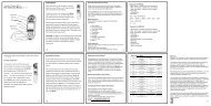
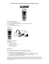
INVENTORY OF CONTENTS1. The indoor weather station2. Remote temperature sensor (model TX4U)3. Instruction manual and warranty cardADDITIONAL EQUIPMENT (not included)1. Four fresh AA 1.5V batteries.2. Phillips screwdriver (for mounting)3
ABOUT WWVBThe NIST (National Institute of Standards and Technology—Timeand Frequency Division) radio station, WWVB, is located in Ft.Collins, Colorado and transmits the exact time signal continuouslythroughout the United States at 60 kHz. The signal can bereceived up to 2,000 miles away through the internal antenna in the<strong>Weather</strong> Station. However, due to the nature of the Earth’sIonosphere, reception is very limited during daylight hours. The<strong>Weather</strong> Station will search for a signal every night when receptionis best. The WWVB radio station derives its signal from the NISTAtomic clock in Boulder, Colorado. A team of atomic physicistscontinually measure every second of every day to an accuracy often billionths of a second a day. These physicists have created aninternational standard, measuring a second as 9,192,631,770vibrations of a Cesium 133 atom in a vacuum. For moreinformation about WWVB please see the NIST website athttp://www.boulder.nist.gov/timefreq/stations/wwvb.htm4
QUICK SET-UP GUIDEHint: Use good quality Alkaline Batteries and avoidrechargeable batteries.1. Have the indoor weather station and remotethermo/hygro sensor 3 to 5 apart.2. Batteries should be out of both units for 10 minutes.3. Place the batteries into the remote thermo/hygrosensor first then into the indoor weather station.(All remote thermo/hygro sensors must be startedbefore the indoor weather station)4. DO NOT PRESS ANY BUTTONS FOR 10MINUTES.In this time the indoor weather station and remote thermo/hygrosensor will start to talk to each other and the indoor weather stationwill show both the indoor temperature and humidity and theoutdoor temperature and humidity. If the indoor weather stationdoes not display all values after the 10 minutes please retry the setup as stated above. After all values are displayed for 10 minutesyou can place your remote thermo/hygro sensor outdoors and setyour time.The remote thermo/hygro sensor should be placed in a dry, shadedarea. The remote thermo/hygro sensor has a range of 80 feet. Anywalls that the signal will have to pass through will reduce distance.An outdoor wall or window will have 20 to 30 feet of resistanceand an interior wall will have 10 to 20 feet of resistance. Yourdistance plus resistance should not exceed 80 ft. in a straight line.NOTE: Fog and mist will not harm your remote thermo/hygrosensor but direct rain must be avoided.5
To complete the set up of your indoor weather stationafter the 10 minutes have passed please follow thesteps in the Detailed Set Up Guide.Note: The remote thermo/hygro sensor transmits a signal every 3minutes; after the batteries have been installed, the indoor weatherstation will search for the signal for a duration of 5 minutes. Ifthere is no temperature reading in the OUTDOOR LCD after 5minutes, make sure the units are within range of each other, orrepeat the battery installation procedure.6
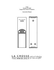
DETAILED SET-UP GUIDEBATTERY INSTALLATIONA. Remote Thermo/hygro Sensor1. Pull the cylindrical rain cover off the remotethermo/hygro sensor.2. Remove the battery cover (located on the backside ofthe remote thermo/hygro sensor, above the mountingpost and bracket).3. Press the arrow and slide the battery cover off.4. Observing the correct polarity install 2 AA batteries.5. Replace battery cover, and place rain cover snuglyonto the remote thermo/hygro sensor.B. Indoor <strong>Weather</strong> Station1. Remove the battery cover. To do this, insert a solidobject in the space provided at the lower-centralposition of the battery cover, then push up and pullout on the battery cover.2. Observe the correct polarity, and install 2 AAbatteries.3. Replace the battery cover.BatteryCoverNote: Immediately after the batteries have been installed, eachLCD (Liquid Crystal Display) will flash, and a tone will sound.Within a few seconds the indoor temperature, indoor relativehumidity, and the weather icons (sun and clouds) will be displayed.If these items are not displayed remove the batteries for 10 secondsand reinstall. If the outdoor temperature is not displayed withinfour minutes, remove the batteries from both units, wait 10seconds, and reinstall. The time will show -:-- and start searchingfor the signal. If it successfully receives the time signal (reception7
is achieved easiest at night), it will display the correct time(factory setting is Eastern time zone).PROGRAM MODEProgramming Note: If 20 seconds is allowed to pass duringprogramming modes, the unit will confirm/set the last informationentered—the display will stop flashing and return to normal timedatereadingsTIME AND DATEThere are two methods by which the time and date can be set:1) Automatically via WWVB reception (only need to set thetime zone in section III).This method requires you to do nothing but wait for the signal tobe received, and to select a time zone (default is Eastern TimeZone). Reception usually takes approximately 6-8 minutes duringoptimal conditions. The best conditions for reception is at night,between midnight and 6:00 am, when there is less atmosphericinterference. To keep your time as accurate as possible, the indoorweather station conducts a WWVB search every night betweenthese hours, and overrides any time that has been set manually.The WWVB tower icon (appearing in the TIME LCD) will flashwhen a search is in progress, will remain steady when the signalhas been received, and nothing will be displayed in all othersituations. If the WWVB time has not been received after 10minutes of battery installation, you may manually set the time orleave the time function alone (reception will occur regardless).8
2) Manually (performed throughout the programming mode.When programming, the manual setting of time and date is notnecessary and can be skipped. Any time information programmedwill be over-written by the reception of the WWVB signal.FUNCTION KEYSThere are four buttons on the <strong>WS</strong>-<strong>7391U</strong>, two on the front and twoon the back. The front two buttons are the “CHANNEL” button(for selecting different remote temperature sensors if added) andthe “RESET” button (for resetting the minimum and maximumtemperatures). The two back buttons are the “SET” button (toenter the programming mode and confirming selections) and the“+” button (to select different settings once in the programmingmode).I. 12/24-Hour Time Format1. Press and hold the “SET” button (on the back of theclock) for 2 seconds or until “12h” or “24h” flashes.2. Press and release the “+” button to select 12-hour or24-hour (“military”) time format.3. Press and release the “SET” button to confirm andadvance to the time setting (skip step 1 and 2 insection II if continuing).9
II. Time SettingNote: This is only necessary if you do not wish to wait for theWWVB reception. All manual set data will be over-ridden by thereception of the WWVB signal based on the time zone selected.1. Press and hold the “SET” button (on the back of theclock) for 2 seconds or until “12h” or “24h” flashes.2. Press and release the “SET” button again, the hourwill flash.3. Press and release the “+” button to advance the hour.Note: In 12h mode “PM” will appear to the left of thetime during PM hours. If the time is not within the PMhours nothing will be displayed. Be sure to set the time tothe correct AM/PM time to ensure automatic reception.4. Press and release the “SET” button, the digits thatrepresent the minutes will flash.5. Press and release the “+” button to advance theminutes.6. Press and release the “SET” button to confirm andadvance to the time zone setting (skip step 1 and 2 insection III if continuing).III. Time Zone SettingThe default (factory set) time zone is EST (Eastern Standard Time)1. Press and hold the “SET” button for 5 seconds oruntil “12h” or “24h” flashes.2. Press and release the “SET” button three more times,“EST” will flash (or other time zone if changedpreviously).10
3. Press and release the “+” button to select yourdesired time zone.The TIME LCD displays the 3 letter abbreviations for thetime zones found in North America. Observe the chartbelow, showing corresponding abbreviations, time zones,and codes.Display TimeZoneHours fromGMTGMT GMT 0AST Atlantic -4EST; Eastern -5CST; Central -6MST; Mountain -7PST; Pacific -8ALA; Alaska -9HAW; Hawaii -104. Press and release the “SET” button to confirm andadvance to the Daylight Saving Time setting (skipstep 1and 2 in section IV if continuing).IV. Daylight Saving Time (DST) Setting1. Press and hold the “SET” button for 2 seconds oruntil “12h” or “24h” flashes.2. Press and release the “SET” button 4 times to reachthe DST selection mode.3. DST 1 is the default setting.4. Press and release the “+” button to select DST 1(recognizes Daylight Saving Time change) or DST 0(does not change with Daylight Saving Time).11
Note: Some locations (Arizona and parts of Indiana) donot follow Daylight Saving Time.5. Press and release the “SET” button to confirm andadvance to the Date setting mode (skip step 1and 2 insection V if continuing).V. Setting the Day, Date and YearNote: This is only necessary if you do not wish to wait for theWWVB reception. All manual set data will be over-ridden by thereception of the WWVB signal based on the time zone selected.1. Press and hold the “SET” button for 2 seconds oruntil “12h” or “24h” flashes.2. Press the “SET” button 5 more times to reach the dayof the week setting mode.3. The two-digit day of the week is flashing (SU is thedefault or factory setting).4. Press and release the “+” button to advance to thecorrect day.5. Press and release the “SET” key to confirm the dayof the week setting and to shift to month setting.6. Press and release the “+” button to advance to thecorrect month.7. Press and release the “SET” key to confirm themonth and advance to the date setting.8. Press and release the “+” key to advance to thecorrect date.9. Press and release the “SET” key to confirm the datesetting and to advance to the year setting.10. Press and release the “+” key to advance to thecorrect year.12
11. Press and release the “SET” button to confirm theyear and to advance to °F and °C selection (skip step1 and 2 in section VI if continuing).VI. Selecting °F OR °C1. Press and hold the “SET” button for 2 seconds oruntil “12h” or “24h” flashes.2. Press and release the “SET” button 9 times to reachthe °F or °C setting mode.3. “°F” is the default setting and the temperatures(inside and remote) will be flashing.4. Press and release the “+” button to select °F to °C.5. Press the “SET” button to confirm and to advance tothe LCD setting (skip step 1 and 2 of section VII ifcontinuing).VII. Setting the LCD Contrast1. Press and hold the “SET” button for 2 seconds, oruntil “12h” flashes.2. Press and release the “SET” key 10 times to reachthe LCD contrast setting mode.3. There are 8 LCD contrast levels to choose from—“Lcd 0” is the lightest, and “Lcd 7” is the darkest.“Lcd 5” is the default setting.4. Press and release the “+” button to toggle throughthe settings.5. Press and release the “SET” button to confirm andexit the programming mode.13
FEATURES OF THE <strong>WS</strong>-<strong>7391U</strong>I. <strong>Weather</strong> ForecastThe weather forecasting feature is estimated to be 75% accurate.By adjusting the sensitivity setting, you can achieve a betteraccuracy of forecast. The weather forecast is based solely upon thechange of air pressure over time. In areas where the weather is notaffected by the change of air pressure, this feature will be lessaccurate.1. <strong>Weather</strong> IconsThere are 3 possible weather icons that will be displayedin the TENDENCY LCD:Sunny—indicates that the weather is expected to improve(not that the weather will be sunny).Sun with Clouds—indicates that the weather is expectedto be fair (not that the weather will be sunny with clouds).Clouds with Rain—indicates that the weather is expectedto get worse (not that the weather will be rainy).The weather icons change when the unit detects a changein air pressure. The icons change in order, from “sunny”to “partly sunny” to “cloudy”. It will not change from“sunny” directly to “rainy”, although it is possible for thechange to occur quickly. If the symbols do not change14
then the weather has not changed or the change has beenslow and gradual. If this happens on a regular basis, itmay be necessary to adjust the weather forecastsensitivity.2. <strong>Weather</strong> Tendency ArrowsOther possible displays in the TENDENCY LCD are 2weather tendency arrows, one that points up and one thatpoints down. These arrows reflect current changes in theair pressure: an arrow pointing up indicates that the airpressure is increasing and the weather is expected toimprove or remain good, an arrow pointing downindicates that the air pressure is decreasing and theweather is expected to become worse or remain poor. Noarrow means the pressure is stable.A storm can be expected if there is a drop of 4 hPa ormore in less than 6 hours, the rain icon is displayed, andthe downward pointing arrow is flashing. The flashingwill stop when the air pressure stabilizes or begins to rise.II. Indoor Temperature, Humidity, and Comfort LevelIndicatorThe current indoor temperature (viewed on the left) and relativehumidity (viewed on the right) are displayed in the INDOOR LCD.The comfort level indicator is located at the center of the INDOORLCD. The comfort level indicator will display a happy face iconwhen the temperature is between 68°F and 79°F (20°C and25.9°C), and the humidity is between 45% and 64%. A sad faceicon will be displayed when the temperature and humidity areoutside the mentioned ranges.15
III. Outdoor Temperature and HumidityThe outdoor temperature and humidity is viewed in theOUTDOOR LCD. When there is more than one remote sensorunit in operation a “boxed” number will appear to the right of thetemperature. This indicates which remote sensor unit (1, 2, or 3) iscurrently displaying its data in the OUTDOOR LCD. (This featureis explained in further detail in the following section—AddingRemote Sensors).IV. Minimum and Maximum Temperature Records (Indoor,Outdoor and Resetting)The <strong>WS</strong>-<strong>7391U</strong> keeps a record of the minimum and maximumtemperatures for both the indoor and outdoor sections. Thesetemperatures can be viewed directly underneath the current indoorand outdoor temperatures. The minimum recorded temperature ison the left and the maximum-recorded temperature is on the right.Resetting the Minimum and Maximum RecordsTo reset both the indoor and outdoor temperature records press andhold the reset button for 5 seconds.Note: This will reset both the indoor and outdoor records, it is notpossible to only reset one or the other.16
V. Adding Additional Remote Sensors (Optional)The <strong>WS</strong>-<strong>7391U</strong> is able to receive signals from 3 differentremote sensors. These extra remote sensors can bepurchased through the same dealer as this unit. A TX4Uwill monitor the temperature and humidity, a TX3U willmonitor temperature and display the temperature on itsLCD and the TX3UP will monitor the temperature via aprobe for measuring soil or water temperatures.Note: When setting up multiple units it is important toinsert batteries first into all the remote sensors, and innumeric sequence. Second install batteries into theindoor weather station. Transmission problems will ariseif this is not done correctly and if the total time for set-upexceeds 6 minutes.VI. Set-up of Multiple Units1. It is necessary to remove the batteries from all unitscurrently in operation.2. Remove the battery covers to all remote sensors.3. Place all remote sensors in a numeric sequentialorder.4. In sequential order, install batteries following thesame battery installation procedures seen in DetailedSet-Up Guide section of this manual.5. Install batteries into the indoor weather station.6. Follow the Detailed Set-Up Guide for programmingand operating instructions.17
VII. Viewing and Operating with Multiple Remote Sensors1. To view the temperature of a different remote sensorpress and release the “CHANNEL” button. A shiftfrom one “boxed” number to the next should beobserved in the OUTDOOR LCD.2. The minimum and maximum temperature of theadditional remote sensor will be displayed below thecurrent temperature of the remote sensor in theOUTDOOR LCD.3. To reset the minimum and maximum temperaturereadings it is necessary to select which remote sensoryou wish to reset. Press and hold the “RESET”button for 5 seconds and the records for the selectedremote sensor will be reset.18
2. The Indoor <strong>Weather</strong> Station1. The <strong>WS</strong>-<strong>7391U</strong> is a wall mount only indoor weatherstation. To mount the display on your wall:2. Fix a screw (not included) into the desired wall, leavingapproximately 3/16 of an inch (5mm) extended from thewall.3. Place the indoor weather station onto the screw using thehanging hole on the backside.4. Gently pull the indoor weather station down to lock thescrew into place.21
TroubleshootingProblem: No reception of WWVB time signalSolution: 1) Wait overnight for signal.2) Be sure indoor weather station is at least 6 feetfrom any electrical devices, such as televisions,computers, or other radio-<strong>controlled</strong> clocks.3) Remove batteries for five minutes, reinsert andleave alone without pressing buttons overnight.4) If there are still problems, contact La CrosseTechnologyProblem: Hour is incorrect (minute and date are correct)Solution: Be sure correct time zone and daylight saving timeare selected.Problem: The LCD is faintSolution: 1) Set the LCD contrast to a higher number2) Replace batteriesProblem: No remote temperature is displayedSolution: 1) Remove all batteries, reinsert into remotesensor(s) first, then indoor weather station.2) Place remote sensor(s) closer to indoor weatherstation.3) Be sure all batteries are fresh.Problem: Remote humidity displays “- -“Solution: 1) A temperature only sensor is being used anddisplayed2) The humidity is outside the range of 19-95%NOTE: For problems not solved, please contact La CrosseTechnology.22
Maintenance and Care Instructions• Extreme temperatures, vibration, and shock should beavoided to prevent damage to the units.• Clean displays and units with a soft, damp cloth. Do notuse solvents or scouring agents; they may mark thedisplays and casings.• Do not submerge in water.• Immediately remove all low powered batteries to avoidleakage and damage.• Opening the casings invalidates the warranty. Do not tryto repair the unit. Contact La Crosse Technology forrepairs.23
SpecificationsTemperature measuring range:IndoorOutdoorRelative humidity measuring rangeIndoor temperature checkingintervalIndoor humidity checking intervalOutdoor temperature and humiditychecking interval (Remotethermo/hygro sensor)Outdoor temperature and humidityreception (indoor weather station)Transmission RangePower SupplyIndoor weather stationRemote thermo/hygro sensorBattery life cycleRecommended battery typeDimensions (L x W x H)Indoor weather stationRemote thermo/hygro sensor32°F to 139.8°F with 0.2°Fresolution. (0°C to 59.9°C with0.1°C resolution) “OFL” displayedif outside this range-21.8°F to 157.2°F with 0.2°Fresolution. (-29.9°C to 69.9°Cresolution) “OFL” displayed ifoutside this range19% to 95% with 1% resolution(“- -” displayed if outside this rangeEvery 10 secondsEvery 1 minuteEvery 1 minuteEvery 3 minutes80 feet (in open space)2 x AA2 x AAApproximately 12 monthsAlkaline6.5 x17.75 x 1.25 inches(171 x 450 x 31mm)1.56 x 0.78 x 4.29 inches(40 x 20 x 110 mm)24
WARRANTY INFORMATIONLa Crosse Technology provides a 1-year warranty on this weatherstation. Contact La Crosse Technology immediately upondiscovery of any defects covered by this warranty.Before sending the <strong>Weather</strong> Station in for repairs, contact LaCrosse Technology. The <strong>Weather</strong> Station will be repaired orreplaced with the same or similar model.This warranty does not cover any defects resulting from improperuse, unauthorized repairs, faulty batteries, or the <strong>Weather</strong> Stationsinability to receive a signal due to any source of interference.LA CROSSE TECHNOLOGY WILL NOT ASSUME LIABILITYFOR INCIDENTAL, CONSEQUENTIAL, PUNITIVE, OROTHER SIMILAR DAMAGES ASSOCIATED WITH THEOPERATION OR MALFUNCTION OF THIS WEATHERSTATION. THIS PRODUCT IS NOT TO BE USED FORMEDICAL PURPOSES OR FOR PUBLIC INFORMATION.THIS PRODUCT IS NOT A TOY. KEEP OUT OF CHILDRE’SREACH.This warranty gives you specific legal rights. You may also haveother rights specific to your State. Some States do no allow theexclusion of consequential or incidental damages therefore theabove exclusion of limitation may not apply to you.25
For warranty work, technical support, or information contactLa Crosse Technology700 East Main StreetSpring Grove, MN 55974Phone: 507.895.7095Fax: 507.895.8000e-mail:support@lacrossetechnology.com(warranty work)sales@lacrossetechnology.com(information on other products)web:www.lacrossetechnology.comAll rights reserved. This handbook must not be reproduced in anyform, even in excerpts, or duplicated or processed using electronic,mechanical or chemical procedures without written permission ofthe publisher.This handbook may contain mistakes and printing errors. Theinformation in this handbook is regularly checked and correctionsmade in the next issue. We accept no liability for technicalmistakes or printing errors, or their consequences.All trademarks and patents are acknowledged.26