RTOP Power Resistors for Mounting onto a Heatsink ... - TE-EPC-LPC
RTOP Power Resistors for Mounting onto a Heatsink ... - TE-EPC-LPC
RTOP Power Resistors for Mounting onto a Heatsink ... - TE-EPC-LPC

You also want an ePaper? Increase the reach of your titles
YUMPU automatically turns print PDFs into web optimized ePapers that Google loves.
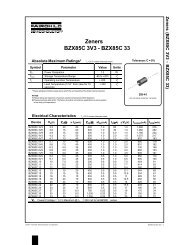
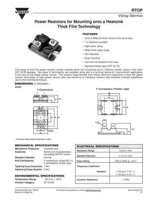
<strong>Power</strong> <strong>Resistors</strong> <strong>for</strong> <strong>Mounting</strong> <strong>onto</strong> a <strong>Heatsink</strong>Thick Film Technology<strong>RTOP</strong>Vishay SferniceFEATURES• Up to 4 different ohmic values in the same case• 1% tolerance available• High power rating• Wide ohmic value range• Non inductive• Easy mounting• Low thermal radiation of the case• Standard Isotop case (SOT 227 B)This series of thick fi lm power resistors include modules which can incorporate up to 4 different resistor values in the sameSOT 227B package. Two types of terminations are available along with a 4 terminal device <strong>for</strong> measurement applicationsin the case of the single resistor version. This product range benefi ts from Vishay Sfernice’s experience in thick fi lm powerresistor technology i.e high power: volume ratio, low tolerance or individual resistors and excellent overload capabilities(due to the trimming technique).DIMENSIONS in millimeters<strong>RTOP</strong>V Connections410 12.5F Connections (“Faston” type)38301523 2515 30 38ø 1.86.312.525ø 4.241019.3• Tolerances unless otherwise specified: ± 0.3mmMECHANICAL SPECIFICATIONSMechanical Protection Insulated caseSubstrateAlumina on insulated base(excluding Q<strong>RTOP</strong> series)Resistive Element CermetEnd Connections V connections: screw M4 x 6F connections: Faston typeTightening Torque Connections 1 NmTightening Torque <strong>Heatsink</strong> 2 NmENVIRONMENTAL SPECIFICATIONSTemperature Range - 55°C to + 125°CClimatic Category 55/125/56ELECTRICAL SPECIFICATIONSResistance Range0.046 to 1MΩStandard Tolerance ± 1% to ± 10%<strong>Power</strong> Rating 20W to 200W at + 25°CTemperature CoefficientStandard ± 300 ppm/˚C (R < 1)± 150 ppm/˚C (R > 1)Insulation Resistance> 10 6 MΩDocument Number: 50045Revision 20-Mar-02For technical questions, contact sfer@vishay.comwww.vishay.com27
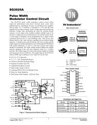
<strong>RTOP</strong>Vishay Sfernice<strong>Power</strong> <strong>Resistors</strong> <strong>for</strong> <strong>Mounting</strong> <strong>onto</strong> a <strong>Heatsink</strong>Thick Film TechnologyPERFORMANCE<strong>TE</strong>STS CONDITIONS TYPICAL DRIFTSMomentary Overload 2.5Pn/5 seconds < ± (0.25% ± 0.05Ω)Rapid Temperature Change 5 cycles - 55°C +125°C < ± (0.25% ± 0.05Ω)Load Life Pn at 25°C 1000 hours < ± (0.5% ± 0.05Ω)Humidity (steady state) 56 days 95% R.H. < ± (0.5% ± 0.05Ω)SPECIAL FEATURESMODEL <strong>RTOP</strong> 200 <strong>RTOP</strong> 100 D<strong>RTOP</strong> 100 D<strong>RTOP</strong> 50 T<strong>RTOP</strong> 40 T<strong>RTOP</strong> 30 Q<strong>RTOP</strong> 35 Q<strong>RTOP</strong> 20<strong>Power</strong> Rating at + 25°Cchassis mounted resistors 200W 100W 100W 50W 40W 30W 35W 20Wunmounted resistors 5W 5W 3.5W 3.5W 2W 2W 1.5W 1.5WThermal Resistance (per resistor) 0.5°C/W 1°C/W 0.5°C/W 1°C/W 0.83°C/W 1.11°C/W 0.71°C/W 1.25°C/WLimiting Voltage 1500V 1500V 500V 500V 300V 300V 300V 300VDielectric Strength 2500V 2500V 2500V 2500V 2500V 2500V base = commonconnections/chassisDielectric Strength - - 4000V 4000V 4000V 4000V 4000V 4000Vconnections/resistorsOhmic Value Range 0.046 to 1MΩ 0.092 to 1MΩ 0.046 to 1MΩ 0.046 to 1MΩTolerance ± 1% to ± 10% ± 1% to ± 10% ± 1% to ± 10% ± 1% to ± 10%Electrical DiagramsRR2R1R2R1R3R2R1R3R4GroundedbaseRShunt Versionwww.vishay.com28For technical questions, contact sfer@vishay.comDocument Number: 50045Revision 20-Mar-02
<strong>Power</strong> <strong>Resistors</strong> <strong>for</strong> <strong>Mounting</strong> <strong>onto</strong> a <strong>Heatsink</strong>Thick Film Technology<strong>RTOP</strong>Vishay SferniceCHOICE OF HEATSINKThe user must choose the heatsink according to the working conditions of the component (power, room temperature).Maximum working temperature must not exceed 125°C. The dissipated power is simply calculated by the following ratio:∆TP =[RTH (j-c) + RTH (c-a)](1)P: expressed in W∆T: difference between maximum working temperature and room temperature.RTH: (j-c): thermal resistance value measured between resistive layer and outer side of the resistor. It is the thermalresistance of the component (see Table Special Features).RTH: (c-a): thermal resistance value measured between outer side of the resistor and room temperature. It is thethermal resistance of the heatsink depending on the heatsink itself (type, shape) and the quality of the fasteningdevice.Example:RTH: (c-a) <strong>for</strong> <strong>RTOP</strong> 200 power rating 130W at ambient temperature + 30°C.Thermal resistance (see table 1) RTH (j-c): 0.5°C/W∆T ≤ 125°C - 30°C - ≤ 95°C∆T 95RTH (j-c) + RTH (c-a) = = = 0.73°C/WP 130RTH (j-c) ≤ 0.5°C/WRTH (c-a) ≤ 0.73°C/W - 0.5°C/W ≤ 0.23°C/WRECOMMENDATIONS FOR MOUNTING ONTO A HEATSINKSurfaces in contact must be carefully cleaned.The heatsink must have an acceptable fl atness: from 0.05mm to 0.1mm/100mm.Roughness of the heater must be around 6.3µm.In order to improve thermal conductivity, surfaces in contact (alumina, heatsink) are laid on with a silicone grease (type SI 340from Rhône-Poulenc or Dow 340 from Dow Corning).Tightening torque on heater: 2 NmFor the electrical connections, it is recommended to use M4 x 6 screws and if necessary a washer of 1mm thickness. Therecommended screw tightening torque is 1 Nm.Document Number: 50045Revision 20-Mar-02For technical questions, contact sfer@vishay.comwww.vishay.com29
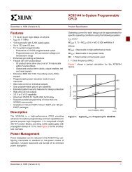
<strong>RTOP</strong>Vishay Sfernice<strong>Power</strong> <strong>Resistors</strong> <strong>for</strong> <strong>Mounting</strong> <strong>onto</strong> a <strong>Heatsink</strong>Thick Film TechnologyOVERLOADSThe applied power is 2.5 x rated power <strong>for</strong> 5 s with a max voltage of 2 x nominal voltage.Accidental overload: The values indicated in the graph below are applicable to resistors in air or mounted <strong>onto</strong> a heatsink. Incase of multi-resistor devices, (D<strong>RTOP</strong>, T<strong>RTOP</strong> and Q<strong>RTOP</strong>) the results apply to each resistor value in the device.ENERGY CURVE1000100ENERGY IN JOULES1010.10.011.10 -7 1.10 -6 1.10 -5 1.10 -4 1.10 -3 1.10 -2 1.10 -1 1OVERLOAD DURATION IN SECONDSPOWER RATING CHARTThe temperature of the heater should be maintained in the limit specifi ed. To improve the thermal conductivity, surfaces incontact should be laid on with a silicon grease and the torque applied on the screw <strong>for</strong> tightening should be around 2 Nm.100<strong>RTOP</strong> D<strong>RTOP</strong> T<strong>RTOP</strong> AND Q<strong>RTOP</strong>80% RA<strong>TE</strong>D POWER60402000 20 40 60 80 100 120 140HEATSINK <strong>TE</strong>MPERATURE IN DEGREES CELSIUSMARKINGSeries, style, ohmic value (in ), tolerance (in %), manufacturing date, VISHAY trade mark.ORDERING INFORMATION<strong>RTOP</strong> 200 3.2 ± 1% ± % VR1 T1 R2 T2MODEL STYLE OHMIC VALUE ABSOLU<strong>TE</strong> TOLERANCE PER RESISTOR CONNECTIONS CUSTOM DESIGN<strong>RTOP</strong> 100 Optional To be precise V: Screw OptionalD<strong>RTOP</strong> 50 ± 1% <strong>for</strong> each F: “Faston” typeT<strong>RTOP</strong> 40 ± 2% resistor VS} <strong>RTOP</strong>Q<strong>RTOP</strong> 30 ± 5 % FS} Shunt35 ± 10 %20www.vishay.com30For technical questions, contact sfer@vishay.comDocument Number: 50045Revision 20-Mar-02