SEE Electrical/CADdy++ - Ige-xao.com
SEE Electrical/CADdy++ - Ige-xao.com
SEE Electrical/CADdy++ - Ige-xao.com
- No tags were found...

Create successful ePaper yourself
Turn your PDF publications into a flip-book with our unique Google optimized e-Paper software.
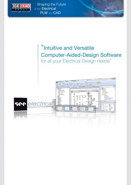
®Shapingthe Futureof the <strong>Electrical</strong>PLM and CAD“Intuitive and VersatileComputer-Aided-Design Softwarefor all your <strong>Electrical</strong> Design needs”
<strong>SEE</strong> <strong>Electrical</strong> - BasicA cost-effective, entry-level solutionNEW2 options: limited to 25 pages or unlimited pages<strong>SEE</strong> <strong>Electrical</strong> - Basic is the ideal entry-level solution for all industries. Its numerous functions andattractive price make it an easily accessible choice for smaller businesses involved in any aspectof electrical engineering.<strong>SEE</strong> <strong>Electrical</strong> offers real-time and automaticfunctions, which incorporate proven technology wellsuited to managing project information and multiplelists.• As a real Windows application, <strong>SEE</strong> <strong>Electrical</strong> readily fitsinto all existing Windows environments.• All functions and <strong>com</strong>mands in <strong>SEE</strong> <strong>Electrical</strong> are easy touse and designed specifically for electrical engineering. Itsintuitive interface means that users can be productive veryquickly, with minimal need for training.• As with most true Windowsapplications, <strong>SEE</strong> <strong>Electrical</strong>users can easily personalizetheir working environment.• User-friendly drawing functionsadapted to the needsof circuit diagram generationfacilitate schematic entry.The rubber band function forexample, allows the movingof <strong>com</strong>ponents horizontally orvertically, while wires remainconnected.• An extensive array of symbolsare readily locatable in thevarious available databases. Inaddition, custom symbols canbe created should the userrequire something that is non-standard.• Various standard and customizable <strong>com</strong>ponent taggingoptions save time and reduce errors. Locking of<strong>com</strong>ponent names especially supports <strong>com</strong>panies doingmaintenance as they can keep existing names and benefitfrom automatisms for new devices though.• All project specific settings are stored within the projectdata and are easily adjusted to the user’s requirements.• Graphical pages (including documents and <strong>com</strong>ponentslists, cable, wire and terminal lists), can be rapidly andprofessionally produced.• Several projects can be worked on simultaneously,allowing the user to copy existing parts or full sheets fromone project to another.• With the integrated Microsoft ActiveX® interface,documents from other Windows applications (includingMicrosoft Word®, Microsoft Excel®) can be embeddedinto the project structure.• The ability to import and export in DWG, DXF, DXB andEnhanced Metafile Format facilitates the exchange ofdrawings with third parties.• For professional looking documentation,pixel imagessuch as BMP, JPEG andPCX files can be inserted intothe title block of an electricaldiagram.• Real-time and automatic functionsconstantly verify projectdata, saving the user valuabletime.• Labels for terminals, wiresand <strong>com</strong>ponents can beproduced by exporting invarious supported printerformats, including Weidmüllerand many others.• Special functions for dimensioning and geometrical designare incorporated, providing a basis for designing controlcabinet and panel layouts.• Hyperlinks can be used to link external documentsor information from the Internet needed for extendeddocumentation to geometric elements.• A <strong>SEE</strong> <strong>Electrical</strong> Viewer is available for free. It allowsanybody to conveniently view and print projects. The“redlining” functionality, available in the software and alsoin the Viewer, enables effective <strong>com</strong>munication betweendesign and manufacturing departments.• A diverse range of page templates is included, and theuser can easily create their own if required.
<strong>SEE</strong> <strong>Electrical</strong> - AdvancedFor the highest level of electrical design<strong>SEE</strong> <strong>Electrical</strong> - Advanced is the final level of <strong>SEE</strong> <strong>Electrical</strong>. It offers a high-end, professionalsystem for electrical diagram design that substantially reduces development times.In addition to all the capabilities of the Basic andStandard levels, the Advanced package equips theuser with further powerful functions. These have beenspecifically designed to enable users to rapidly andefficiently develop and manage <strong>com</strong>plex electricalprojects.• Functions like “Autoconnect” and “Orthogonal Wiring” giveeven more <strong>com</strong>fort in drawing.• The effort necessary to carry out changes is clearly reduced:single pages can be copied or moved by “drag and drop”.Multiple pages can also be copied in one step.• By double-clicking on any cross-reference, the user cannavigate through a <strong>com</strong>plex project quickly and effortlessly.• Using a database driven translationtool, entire projects can be convertedinto different languages at the clickof a mouse, whilst texts can alsobe translated individually if required.Additionally, the selection of a“codepage” permits the display ofWestern European and e.g. Cyrillicor Greek letters in a diagram at thesame time. While typing the text,access to the translation databaseis enabled and therefore pre-storedtexts can be overtaken by doubleclicking.• The automatic numbering mode for PLC operands canbe predefined (hexadecimal, decimal, or octal), and PLCassignment lists can be imported in Microsoft Excel®format.• A useful function can change all the page templatesfor an entire project or for some pages only, allowingfor the customisation of project templates for differentcustomers.• Database editors incorporate a wide range of sorting andfiltering functions therefore reducing the time spent onchanges. For example they enable terminal blocks to beautomatically renumbered to <strong>com</strong>ply with new or reviseddefinitions.• The smart functionality “Navigation from database list todrawing” helps find objects quicker and is really easy touse. Also some graphical lists (<strong>com</strong>ponent, terminal, PLCI/O, cable and device list and product assembly) allownavigation to the diagrams.• The functionality to manage parts which do not need to bein drawings by list (spare terminals, mounting material …)allows either:- To predefine material and to position it later in the circuitdiagram by using a pick list.- Or to help manage material that does not appearin a diagram but is necessary for the part list.It is also possible to read in an Excel file thatcontains the additional material, for example if thisinformation is already prepared in a PDM system.Also Spare terminals, end- or separation plates can bemanaged in the same way.• A custom graphical list generator allows users to createtheir own bespoke project reports. This can either beachieved with the built-in interface, or by the use of SQLstatements.• Merging projects with differentfunction/localisation allows multipleusers to work on specific areas ofthe same project.• If several similar projects / drawingsneed to be produced,<strong>SEE</strong> <strong>Electrical</strong> Advanced offersa powerful ‘auto-diagramming’function. This tool is able togenerate entire projects orgroups of symbols from MicrosoftExcel® and Access® files.• The sorting order of different kinds of documents can beadapted, so that each user can readily print exactly whatthey need, in the order and size they require.• Workspaces are configurable, this means, you can hidelists not in use, define specific SQL queries and generatelists in your own formats by this. Workspace, page and<strong>com</strong>ponent text attributes can be defined or renamed.Additionally user defined symbol types can be generated.With the «List & Labelling» tool in the integrateddatabase, <strong>SEE</strong> <strong>Electrical</strong> offers powerful and fullyautomated generation of labels and tags.All popular worldwide labelling formats, includingAvery, Zweckform, Herlitz and Leitz are fullyintegrated into the system.
Additional modulesCabinet LayoutSimple control cabinet and panel designIt allows the professional design of control cabinets and panels within <strong>SEE</strong> <strong>Electrical</strong>.The module can be <strong>com</strong>bined with circuit diagram module in Standard or Advanced level.• <strong>SEE</strong> <strong>Electrical</strong> offers the automatic linking of symbols in an electrical schematic to those placed in a cabinet. Componentsplaced in circuit diagrams are directly found in the pick list of cabinet and vice versa. Used <strong>com</strong>ponents disappear fromthe list. Like this the need to control <strong>com</strong>ponents placed manually which leads to errors is as well avoided as the boringretyping of <strong>com</strong>ponent names.• Elements inserted into cabinets are correctly scaled and obtained from the “type database”, either from the length andwidth of the <strong>com</strong>ponent, or from imported or user-defined symbol.• Depending on individual needs design can start with circuit diagrams or cabinet.• A variety of measuring, dimensioning and other specialized CAD functions assist in the production of professional lookingdocuments.• DIN rails and cable/wire channels can be inserted as required, facilitating the construction of organized and logicalcabinets.• Terminal strips used in cabinets may also be viewed in the <strong>SEE</strong> <strong>Electrical</strong> graphical terminal matrix.House InstallationA versatile CAD module for producing electrical installation plansIt can be used with Circuit Diagram module in each level.• Easy to use with a <strong>com</strong>prehensive range of symbols designed specifically for the electrical side of building servicesengineering.• In addition, custom symbols can easily be generated. Together with the availability to insert text at any positionindividual ideas in design can be realized.• Functions include automatic symbol rotation, easy copying, and tagging.• Building plans obtained directly from an architect, may be read in through the DWG/DXF/DXB interface.• Walls, doors, windows, and many other objects can easily be inserted from the symbol database, allowing simplebuilding drawings to be created by the user.• Various lists, containing cable and <strong>com</strong>ponent information, can readily be generated and exported in Microsoft Excel®or ASCII format.• Tools for area calculation of the rooms and insertion of cable channels are available in the Standard level.• The export of lists in Excel-Format allows easy passing of data to solutions generating offers.Open DataMore efficient data exchange: export of several database lists in one step.Save data entry time: changes can be made in Microsoft Excel® quicker because the content of important lists(document list, product list, terminal list, wire list, cable list, PLC list,…) can be reimported to the <strong>SEE</strong> <strong>Electrical</strong>workspace it originated from. Doing this the module helps to follow the workflow a lot of <strong>com</strong>panies are getting used toelectrical data have to be changed by people not using the <strong>Electrical</strong> CAD system at all.3D Cabinet Layout - a plugin for SolidWorks(only in <strong>com</strong>bination with Standard or Advanced level of <strong>SEE</strong> <strong>Electrical</strong>)Save design time: it connects full 3D functionality to user-friendly <strong>SEE</strong> <strong>Electrical</strong> designing appication.- Components from the <strong>SEE</strong> <strong>Electrical</strong> workspace rotate and attach automatically to the rails.- Automatic creation of a <strong>com</strong>ponent if it is not present in SolidWorks (automatic analysis of the electrical diagram).- Tagging can be changed in SolidWorks and automatically synchronized in the electrical design. Through the linkingto <strong>SEE</strong> <strong>Electrical</strong> changes are automatically made in the circuit diagrams.Components deleted in circuit diagrams are marked in the cabinet and can therefore easily be found.Avoid panel mounting fitting errors: Using the advantages of both <strong>Electrical</strong> and Mechanical CAD packages, theinterface guarantees that all equipment used in the electrical diagrams are found in the cabinet and that no conflict willappear at the mounting stage.Intelligent PDFThis module generates an “intelligent” PDF which allows navigating in a given project with the help of cross references. It also generates an overviewof the project tree and of the <strong>com</strong>ponents. If hyperlinks are defined in a workspace, they are available in PDF-files generated with this module too.The module allows users to generate PDF-documents showing the workspace pages in multiple languages; if the project has been translated before(translation functionality requires Advanced level).Additionally watermarks can be generated.Environment SynchronizerCompanies using multiple licences of <strong>SEE</strong> <strong>Electrical</strong> have a challenge to keep all installations up to date especially if users often take their laptop to thefield and because of this disconnect form local network. The «Environment Synchronizer» module allows the administrator to prepare files that changedon the server. As soon as a user returns to the <strong>com</strong>pany and connects to the intranet <strong>SEE</strong> <strong>Electrical</strong> is automatically updated at first start. No user actionis necessary.IEEE Circuit DiagramsThe IEEE Circuit Diagram module allows the generation of documentation <strong>com</strong>pliant with the standards for the US, Canadian and correspondingmarkets.Intelligent Drawing LegacyThis module is a very useful tool for maintenance services as well as any department managing paper or DXF/DWG plans.It offers two kinds of functionalities, which can be used stand alone each or together:1. (Basic level) Processing of scanned data: import several files in one step into several pages. If symbols are inserted automatically a white area coversthe scanned picture, which is saving a lot of time.2. (Standard level) Recognition of patterns imported via DXF-/DWG. After the definition of standard symbols, the imported plans can be made intelligent.Then after the generation of cross references, graphical lists etc. is possible.3. Advanced level: offers both kinds of functionalities.Solidworks EPDM interfaceThe interface allows secure storing and indexing <strong>SEE</strong> <strong>Electrical</strong> documents in Solidworks Enterprise PDM® by Dassault Systèmes.PDM ConnectGeneric interface to PDM software.
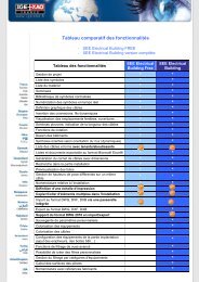
Functionality offered by <strong>SEE</strong> <strong>Electrical</strong> Basic Standard AdvancedProject manager • • •Real-time lists for: <strong>com</strong>ponents, terminals, parts, contacts, cables, cable cores, wires, PLCI/Os, documents • • •Filtering/sorting into lists + storing the filter or sorting • • •Multiple symbol libraries (including IEC) with graphical overview, grouping and searching • • •Creation of custom symbols and drawing macros • • •Real-time <strong>com</strong>ponent numbering and cross referencing • • •Real-time connection and open contacts check up • • •Locking of <strong>com</strong>ponent names • • •Graphical cable definition - including user defined symbols • • •Custom project template creation • • •Bi-directional <strong>com</strong>patibility with other CAD systems (DWG, DXF and DXB) • • •Microsoft ActiveX® interface • • •Importing of images (JPG, BMP, PCX...) • • •Copying of symbol groups between projects • • •Working on multiple projects simultaneously • • •Customizable working environment • • •Standard CAD drawing facilities and dimensioning capabilities • • •Support for hyperlinks on graphics • • •Redlining functionality • • •512 available layers • • •Auto-backup feature • • •Export in Enhanced Metafile Format and XML • • •Export formats for Weidmüller and other label printers • • •Integrated ‘type’ database • •Import of manufacturer’s data into type database in Microsoft Excel® format • •Display type information on <strong>com</strong>ponents • •Support for finding a type with necessary number of contacts for coils and <strong>com</strong>ponents withauxiliary contacts • •Contact mirror display for coils • •Automatic contact numbering of coils-and <strong>com</strong>ponents with auxiliary contactsSupport of automatic renumbering the contacts • •Checking for overloaded contacts in coils-and <strong>com</strong>ponents with auxiliary contacts • •Completing <strong>com</strong>ponents like coils, multilevel terminals, connectors, … • •Cable management (cable type database) • •Handling of deck terminals, Management of connectors • •PLC I/O manager • •Function/location management + graphical function/Location boxes • •Graphical signal management with four predefined signal properties /wire numbering inseveral formats • •Wire directions display and editing • •User definable numbering method for all elements and references • •Find and replace text throughout entire project • •Insertion of pages and deletion of pages gaps • •Duplicate <strong>com</strong>ponent name check • •Database editors (single entry editing) • •Graphical terminal plan with automatic detection of up to ten bridge types • •Graphical cable plan including spare cores + Wiring list • •Part list sorted by function/locationAutoconnect• ••Draw orthogonal x-pole wires•Cross-reference navigator (go to) with marking function (<strong>com</strong>e from)•Navigation from Database and specific Graphical lists to drawings•Database manager for functions/locations/products /products (aspects) including ability tomanage nested aspects•PLC operands numbered automatically in several available formats + Importing of PLCassignment lists in Microsoft Excel® format•Generate cable names automatically•Configure project tree allowing for custom graphical and database lists•User defined lists and <strong>com</strong>ponents•Configuration of multicores•Freely configurable signal properties•Language translation of <strong>com</strong>plete projects/ Access to the texts available in the translationdatabase•Changing of page templates for an entire project or a part of the project•Copy multiple pages and all sheets of a function in a project to another one•Advanced database editors (editing of several entries at once)•Renumbering of entire terminal strips, renumbering of cables•Insert <strong>com</strong>ponents/terminals not in drawing by list•Terminal plan with graphics and terminal row picture plan•Cable terminal row plan•Connector matrix and plan•Product assembly list + Compressed BOM + Device list•Database list with texts from callouts: usable for revision management•Sorting of cables and their cores according to function/location•Find and replace symbols throughout current page or entire project•List and label editor•DWG/DXF/DXB multi-import and SVG/DWF multi-export•IGE+XAO Group25 bld Victor Hugo - BP 9031231773 Colomiers - FranceTel: +33(0)5 62 74 36 36Fax: +33(0)5 62 74 36 37