User Guide 1SAFE PDF | 350 Ko - BEA Pedestrian
User Guide 1SAFE PDF | 350 Ko - BEA Pedestrian
User Guide 1SAFE PDF | 350 Ko - BEA Pedestrian

Create successful ePaper yourself
Turn your PDF publications into a flip-book with our unique Google optimized e-Paper software.
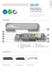
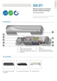
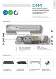
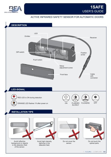
<strong>1SAFE</strong>USER’S GUIDEACTIVE INFRARED SAFETY SENSOR FOR AUTOMATIC DOORSDESCRIPTIONEmitterLEDReceiverDIP-switchFixationscrewPush buttonSetupadjustment screwFront faceCablewithconnectorLED-SIGNALRED LED is ON during detectionORANGE LED flashes 1X after power onONFLASHESSLOWLYFLICKERSOFFINSTALLATION TIPSAvoid reflectivebackground or objectsin the detection fieldof the sensor.Avoid high intensitylightning in thedetection field.Do not cover thesensor.Do not touch theoptical parts.1/4 1/4
UNCOVEREDZONEADDITIONAL ADJUSTMENTSWhen the application requires specific adjustments, you canadapt the sensor by using the dip switches.ON DIP1 2 3 41SETUPONDIP1 2 3 4RED-GREEN+OFFOFF(Factory values)Automatic modeDo not touch the screw. Itshould be positioned asshown.Push the push buttonshortly to launch anautomatic setup.LED flashes RED-GREEN.OKONDIP1 2 3 4ONManual modeWhen?- low reflectivity of background- no background or mounting height > 3m- mounting height < 1.6m- uncovered zone > 40cmHow?Decrease (-) or increase (+) the uncoveredzone and check it by moving a white paperup and down under the sensor.-+GREENRED4x ORANGESwitch to manual modeDo not move the whitepaper horizontally!2ON DIP1 2 3 4Small (25cm at 2.2m)ONDIP1 2 3 4Big (40cm at 2.2m)When?When increased door safety is required.Relaunch a setup after changing dip switch 2When?When increased immunity to disturbancesis required.Relaunch a setup after changing dip switch 23ONDIP1 2 3 4Frequency 1ONDIP1 2 3 4Frequency 2When?When 2 or more sensors are installed inproximity to each other, it is recommended tochoose different frequencies to avoid crosstalk.F1F2When?When 2 or more sensors are installed inproximity to each other, it is recommended tochoose different frequencies to avoid crosstalk.F1F2FREQUENCY4ONDIP1 2 3 4Monitoring Active HighONDIP1 2 3 4Monitoring Active LowMONITORINGWhen?When the monitoring input mode is active highorwhen no monitoring is required.When?When the monitoring input mode is active low.3/4
TROUBLESHOOTINGSYMPTOM POSSIBLE CAUSES CORRECTIVE ACTIONThe sensor detectseratically.Launch setup and check adjustment.Check if proximate modules havedifferent frequencies.Increase the uncovered zone.The LED is OFF,but the relay “clicks”.OFFThe monitoring mode is wrong.The wiring is not correct.Change the position of DIP 4.Check wiring: connect RED andBLUE to monitoring output.If the door control has no monitoring:do not connect RED and BLUE wires.The red LED ispermanently ON.REDBad adjustment of the uncovered zone.The signal received from backgroundis too weak.The distance to the floor has changeddue to external factors.Launch a manual setup.Launch a manual setup.Launch a new setup.The red LEDflickers.REDThe sensors interfere with each otherdue to overlapping detection zones.Increase the distance between thesensors or select a differentfrequency on each sensor.The red LEDflashesduring setup.REDYou are standing inside the detection field.Range is too short.Step outside the detection field.Check if the sensor is installedcorrectly.The orange LEDflashes 4xduring setup.4x ORANGEThe signal received from background istoo weak.Launch a manual setup.TECHNICAL SPECIFICATIONS42.0608 - V3 / 01.13Technology:Detection mode:Detection field:Response time:Mounting height:Supply voltage:Mains frequency:Max. current consumption:Standard output:Max. contact voltage:Max. contact current:Max. switching power:Hold time:Reflectivity:Temperature range:Degree of protection:Norm conformity:Dimensions:Housing material:Length of main cable:active infraredpresence detection by distance measurement35mm x 70mm (at 2.2m mounting height)64ms0.6m - 3m12V - 24V AC/DC -5% / + 10%50 - 60 Hz120mA @ 24V AC / 80mA @ 24V DCrelay (free of potential contact)42V AC/DC1A (resistive)30W (DC) / 60VA (AC)0.5smin. 10% at IR-wavelength of 850nm-25°C - +55°C; 0-95% rel. humidity, non condensingIP53Electromagnetic compatibility (EMC) according to 2004/108/EC144mm (L) x 40mm (H) x 50mm (D)ABS (black)2.5mMonitoring input:Max. contact voltage: 30VVoltage threshold:1 optocoupler (free of potential contact)High state: >10VLow state: