Roller Chain - Tsubaki
Roller Chain - Tsubaki
Roller Chain - Tsubaki

You also want an ePaper? Increase the reach of your titles
YUMPU automatically turns print PDFs into web optimized ePapers that Google loves.
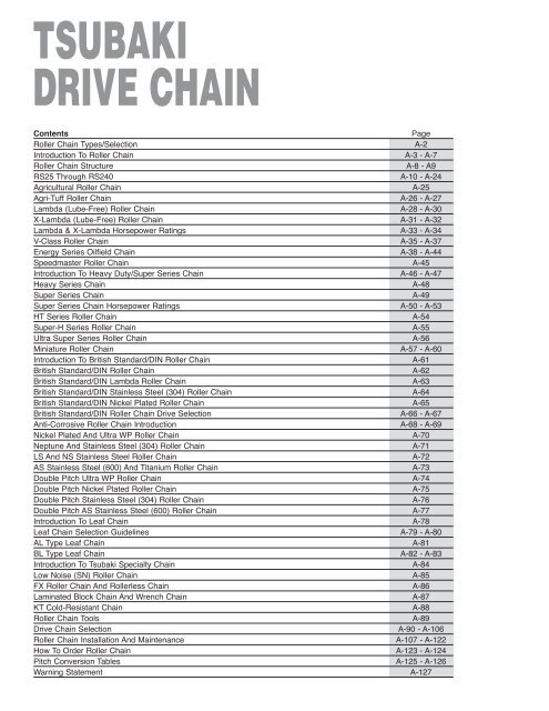
TSUBAKIDRIVE CHAINContentsPage<strong>Roller</strong> <strong>Chain</strong> Types/Selection A-2Introduction To <strong>Roller</strong> <strong>Chain</strong> A-3 - A-7<strong>Roller</strong> <strong>Chain</strong> StructureA-8 - A9RS25 Through RS240 A-10 - A-24Agricultural <strong>Roller</strong> <strong>Chain</strong> A-25Agri-Tuff <strong>Roller</strong> <strong>Chain</strong> A-26 - A-27Lambda (Lube-Free) <strong>Roller</strong> <strong>Chain</strong> A-28 - A-30X-Lambda (Lube-Free) <strong>Roller</strong> <strong>Chain</strong> A-31 - A-32Lambda & X-Lambda Horsepower Ratings A-33 - A-34V-Class <strong>Roller</strong> <strong>Chain</strong> A-35 - A-37Energy Series Oilfield <strong>Chain</strong> A-38 - A-44Speedmaster <strong>Roller</strong> <strong>Chain</strong> A-45Introduction To Heavy Duty/Super Series <strong>Chain</strong> A-46 - A-47Heavy Series <strong>Chain</strong> A-48Super Series <strong>Chain</strong> A-49Super Series <strong>Chain</strong> Horsepower Ratings A-50 - A-53HT Series <strong>Roller</strong> <strong>Chain</strong> A-54Super-H Series <strong>Roller</strong> <strong>Chain</strong> A-55Ultra Super Series <strong>Roller</strong> <strong>Chain</strong> A-56Miniature <strong>Roller</strong> <strong>Chain</strong> A-57 - A-60Introduction To British Standard/DIN <strong>Roller</strong> <strong>Chain</strong> A-61British Standard/DIN <strong>Roller</strong> <strong>Chain</strong> A-62British Standard/DIN Lambda <strong>Roller</strong> <strong>Chain</strong> A-63British Standard/DIN Stainless Steel (304) <strong>Roller</strong> <strong>Chain</strong> A-64British Standard/DIN Nickel Plated <strong>Roller</strong> <strong>Chain</strong> A-65British Standard/DIN <strong>Roller</strong> <strong>Chain</strong> Drive Selection A-66 - A-67Anti-Corrosive <strong>Roller</strong> <strong>Chain</strong> Introduction A-68 - A-69Nickel Plated And Ultra WP <strong>Roller</strong> <strong>Chain</strong> A-70Neptune And Stainless Steel (304) <strong>Roller</strong> <strong>Chain</strong> A-71LS And NS Stainless Steel <strong>Roller</strong> <strong>Chain</strong> A-72AS Stainless Steel (600) And Titanium <strong>Roller</strong> <strong>Chain</strong> A-73Double Pitch Ultra WP <strong>Roller</strong> <strong>Chain</strong> A-74Double Pitch Nickel Plated <strong>Roller</strong> <strong>Chain</strong> A-75Double Pitch Stainless Steel (304) <strong>Roller</strong> <strong>Chain</strong> A-76Double Pitch AS Stainless Steel (600) <strong>Roller</strong> <strong>Chain</strong> A-77Introduction To Leaf <strong>Chain</strong> A-78Leaf <strong>Chain</strong> Selection Guidelines A-79 - A-80AL Type Leaf <strong>Chain</strong> A-81BL Type Leaf <strong>Chain</strong> A-82 - A-83Introduction To <strong>Tsubaki</strong> Specialty <strong>Chain</strong> A-84Low Noise (SN) <strong>Roller</strong> <strong>Chain</strong> A-85FX <strong>Roller</strong> <strong>Chain</strong> And <strong>Roller</strong>less <strong>Chain</strong> A-86Laminated Block <strong>Chain</strong> And Wrench <strong>Chain</strong> A-87KT Cold-Resistant <strong>Chain</strong> A-88<strong>Roller</strong> <strong>Chain</strong> Tools A-89Drive <strong>Chain</strong> Selection A-90 - A-106<strong>Roller</strong> <strong>Chain</strong> Installation And Maintenance A-107 - A-122How To Order <strong>Roller</strong> <strong>Chain</strong> A-123 - A-124Pitch Conversion Tables A-125 - A-126Warning Statement A-127
<strong>Tsubaki</strong> <strong>Roller</strong> <strong>Chain</strong>Types/SelectionClassificationGeneralRS <strong>Roller</strong> <strong>Chain</strong>LAMBDAAdvanced FeaturesANSI Standard(excludes some items)Special sintered bushingDrive <strong>Chain</strong>Lube-FreeLAMBDA-NPX-LAMBDACU-LAMBDABS-LAMBDANickel PlatedUltra-Long LifeFor curved driveBritish and DIN standardSUPERImproved max. allowable load and tensile strengthSUPER seriesSUPER-HRS-HTStronger than SUPERImproved tensile strengthUSUltra-StrongAnti-CorrosionCorrosion ResistantSlightly anti-corrosiveHeat resistant /Anti-corrosiveHighly anti-corrosiveNPPCWPSSNEPTUNELSASNSTIPC-SYNickel PlatedSpecial coatingSpecial double coatingSUS304 + engineering PlasticSUS304SUS304 + engineering plasticMax. allowable load = SS × 1.5SUS316TitaniumTitanium + engineering plasticColdresistantKT–40C to +60C(–40F to +140F)Low NoiseSNLow noiseCurvedCUFor curved driveBritish StandardSpecialtyBSFXROLLERLESSWRENCHBLOCKISO-B seriesDurability and flexabilitySteel bushedExtended pinsLaminated blocksMiniatureMINIQuiet, compact, lightweightAgriculturalAGRIAGRI-TUFFLowspeed, moderate loadHigher strength/wera lifeLeafLEAFHigher tensile strengthA-2
Introduction to<strong>Tsubaki</strong> <strong>Roller</strong> <strong>Chain</strong>This Drive <strong>Chain</strong> Catalog outlines the important points relating to selection, installation, and maintenance of each TSUBAKI <strong>Roller</strong> <strong>Chain</strong>.Make sure to read this catalog before using the chain, and follow the correct selection procedures and method of use. Furthermore,please fully explain matters relating to installation and maintenance to those performing these tasks.Before UseOrdinary TransmissionLifting TransmissionDrive <strong>Chain</strong>CautionThe horsepower ratingstables in this catalog(excluding SUPER <strong>Chain</strong>)are for RS <strong>Roller</strong> <strong>Chain</strong>s andLambda <strong>Roller</strong> <strong>Chain</strong>s whereconnecting links havingundergone the ring coinprocess and 2-pitch offsetlinks are used.Shuttle TractionPin Gear Drive<strong>Roller</strong> <strong>Chain</strong> Safety Use■ Clear the area of all personnel when lifting <strong>Roller</strong> <strong>Chain</strong>.■ Install safety equipment to prevent injuries and damage to equipment in the eventof <strong>Roller</strong> <strong>Chain</strong> breakage.■ Inspect and replace worn <strong>Roller</strong> <strong>Chain</strong> periodically.■ Wear elongation may cause <strong>Roller</strong> <strong>Chain</strong> to break and climb up on the sprocket.(Wear life can be extended by periodically applying lubrication, or by using the lubefreeLambda <strong>Chain</strong> series.)■ Overload may cause <strong>Roller</strong> <strong>Chain</strong> to break.(Overload breakage can be avoided through careful selection, considering inertia orby using identically-sized SUPER <strong>Roller</strong> <strong>Chain</strong>.)■ Unfavorable environmental conditions such as corrosion may cause eventual <strong>Roller</strong><strong>Chain</strong> breakage.(This can be avoided by making sure the chain doesn’t come in contact withcorrosive liquids or steam, etc. Alternatively, the Anti-Corrosive series isrecommended.)■ Correctly install <strong>Roller</strong> <strong>Chain</strong> to avoid misalignment or uneven wear and possiblebreakage.A-3
Introduction to<strong>Tsubaki</strong> <strong>Roller</strong> <strong>Chain</strong>Power transmission machines use chains, gears, or belts. The table below provides a comparison of typical applications. In general,chain is an economical part of power transmission machines for low speeds and large loads. However, it is also possible to use chainin high-speed conditions like automobile engine camshaft drives. This is accomplished by devising a method of operation and lubrication.Drive <strong>Chain</strong>General Comparison ofTransmission ElementsSynchronizationTransmissionEfficiencyAnti-Shock<strong>Roller</strong> <strong>Chain</strong> Tooth Belt V Belt■■■ ■ ▲▲ ❍ ■▲Spur Gear■■▼Noise/Vibration▲ ■ ■▼SurroundingConditionsAvoid water and dust(Corrosion Resistant<strong>Roller</strong> <strong>Chain</strong> is available)Avoid heat, oil,water, and dustAvoid heat, oil,water, and dustAvoid water anddustSpaceWeightHigh SpeedLow LoadLow SpeedHigh LoadLubrication▼ ■ ❍■Compact/Light Weight▲Slightly heavy pulley▼Heavy wide pulley▼ Necessary ■ Unnecessary ■ Unnecessary❍❍Less durability due to lownumber of engaging teeth▼ NecessaryLayout FlexibilityExcess Load onBearing■ ❍ ▲■ ❍ ▼▼■■ Excellent ❍ Good ▲ Fair ▼ PoorFeatures & Points toNote about <strong>Roller</strong> <strong>Chain</strong>TransmissionFeatures1. Accommodates large speed reductions/increases (Usually up to 1 : 7)2. <strong>Chain</strong> can accommodate long shaft center distances (normally less than 4 m), and ismore versatile.3. It is possible to use chain with multiple shafts or drives with both sides of the chain.4. Ease of installation and replacement (easy to cut and connect chains).5. Drive use is possible even when shafts are vertical, as long as the chain receivessupport in short distances between the shafts.6. Standardization of chains under the American National Standards Institute (ANSI), theInternational Standardization Organization (ISO), and the Japanese IndustrialStandards (JIS) allow ease of selection.7. The sprocket diameter for a chain system may be smaller than a belt pulley, whiletransmitting the same torque.8. Sprockets are subject to less wear than gears because sprockets distribute the loadingover their many teeth.9. There is high shock absorbency compared with gears.Points to Note1. <strong>Chain</strong> has a speed variation, called chordal action, which is caused by the polygonaleffect of the sprockets.(Shock can be reduced under the same speed ratio, by either reducing the chain pitchor increasing the number of sprocket teeth.)2. During transmission, a particular method of lubrication is necessary according to speed.3. <strong>Chain</strong> wears and elongates, so you need to consider measures for adjusting chainslack.4. <strong>Chain</strong> is weak when subjected to loads from the side. It needs proper alignment.A-4
Introduction to<strong>Tsubaki</strong> <strong>Roller</strong> <strong>Chain</strong>Explanation of Terms1. ANSI Standard Minimum Tensile Strength (Tensile Breakage Strength)This is the Minimum Tensile Strength determined by ANSI. If a roller chain breaks from atensile load below this value, then it does not surpass ANSI standards. In the case ofmulti-strand roller chain, the single strand value is multiplied by the number of strands.2. Average Tensile StrengthThis is a fracture load reading obtained after a long period of actual tensile strength testingof a large number of chain strands. Of course, when any given strand of roller chainfractures, this value may be higher or lower, so it does not represent a guaranteed value.This value differs depending on the manufacturer.3. Minimum Tensile StrengthThis is a minimum value determined by statistical processing at TSUBAKI. If any rollerchain fractures by a tensile load below this value, then it does not surpass the standards.This value differs depending on the manufacturer.Drive <strong>Chain</strong>Minimum ANSI StandardTensile Strength<strong>Tsubaki</strong> Minimum Tensile StrengthAve. Tensile StrengthFrequencyTensile StrengthFig. 1 Relationship between three tensile strengths.4. Tensile Strength Testing MethodAs shown in Fig. 2, roller chain with over five links is fixed at both ends by clevises and isstretched until fracture occurs. The type of fracture is indicated by breakage of the rollerchain or failure of its parts (Fig. 3).Fig. 2 Tensile strength testFig. 3 Shape of fractureA-5
Introduction to<strong>Tsubaki</strong> <strong>Roller</strong> <strong>Chain</strong>Drive <strong>Chain</strong>5. Maximum Allowable LoadThe maximum allowable load is the tension load for which a chain is rated to carry inrunning operation. Proper chain tension is critical because excessive tension can causeaccelerated wear/breakage or chain overload and excessive slack can cause roughchain operation and may result in the chain skipping a sprocket tooth.The use of one-pitch offset links reduces the maximum allowable load – it now becomes65% of the maximum allowable load of the main chain.Two-pitch offset links do not change the maximum allowable load of the main chain.In Figure 4 below, the maximum allowable load is indicated by Pmax.Pmax = (Pm + Pa) = 2.2PaWhere a new roller chain with over 5 links receives a repetitive load with a frequency of10 6 .Fig. 4 Summary chart for repetitive loadsLoadTime6. Horsepower Ratings TableRS <strong>Roller</strong> <strong>Chain</strong> and SUPER <strong>Roller</strong> <strong>Chain</strong> HP rating tables show HP values that allow15,000 hours of operation using a two-shaft drive and 100 pitches of roller chain underconditions 1 - 5 below. The HP ratings table of LAMBDA chain is based on conditions 1- 4 and shows HP rating values when LAMBDA chain is used with two shafts. Lambda<strong>Chain</strong> has more than 14 times the wear elongation of Standard RS <strong>Roller</strong> <strong>Chain</strong>operated without lubrication (#120 and #140 have five times). X-LAMBDA has morethen five times the wear elongation life of Lambda <strong>Roller</strong> <strong>Chain</strong>.1) The chains are operated under ordinary conditions where the ambient temperature is–10°C ~ +60°C (+14°F ~ +140°F) and there is no abrasive dust.2) There are no negative effects from corrosive gasses or a high humidity.3) The two transmission shafts are in a horizontal position and the chains are properlyinstalled.4) There is minimal fluctuation in load during transmission.5) The recommended lubrication system and lubricant shown in the HP rating tables isused for RS <strong>Roller</strong> <strong>Chain</strong> and SUPER <strong>Roller</strong> <strong>Chain</strong>.7. Moment of Inertia (I / J / GD 2 )Moment of Inertia is used to show the degree of inertia in rotational movement, in otherwords, “rotation difficulty”, or “rotation ease.” This is equivalent to the mass (weight) ofthe object being used for straight-line transmission.A-6
Introduction to<strong>Tsubaki</strong> <strong>Roller</strong> <strong>Chain</strong>After almost a century of chain design, engineering and manufacturing experience, you can count on <strong>Tsubaki</strong> standard roller chain todeliver consistent superior performance and longer life. All minimizing your downtime and maximizing your output. And all for a price alot less than you might think. From the best heat-treated steel for the job to ground-breaking patents, you can trust <strong>Tsubaki</strong> to deliverthe quality difference you can see.Drive <strong>Chain</strong><strong>Tsubaki</strong>’s Patented LubeGrooves Extend Wear Lifeand Performance by up to30%Long Lasting Solid <strong>Roller</strong>sProvide Greater FatigueLife and Durability at HighSpeedsPrecision RivetingProcess Helps to WithstandSide Load ImpactWide Waist Link Plates ProvideTensile Strength and MaximumAllowable Load that Exceeds ANSIStandards<strong>Tsubaki</strong>’s Patented Ring CoiningGenerates UnsurpassedConnecting Link StrengthA-7
<strong>Roller</strong> <strong>Chain</strong> StructurePin LinkPress Fit<strong>Roller</strong> LinkPress FitSlip FitWidth between<strong>Roller</strong> Link PlatesPinDrive <strong>Chain</strong>1. Basic StructurePress Fit<strong>Roller</strong>Bushing<strong>Roller</strong>Diameter Pitch<strong>Roller</strong> Link PlateThree Basic DimensionsPitch, <strong>Roller</strong> Diameter and Widthbetween <strong>Roller</strong> Link Plates areknown as the “Three BasicDimensions of <strong>Roller</strong> <strong>Chain</strong>.”When these three dimensions areidentical, roller chain andsprockets are dimensionallycompatible.* Slip FitWhen the shafts and holes arefitted together, there is acontinuous loose fit. This is a fitwhere the range of tolerance forthe hole is larger than the rangeof tolerance for the shaft (pin orbushing).* Press FitWhen the shafts and holes arefitted together, there is acontinuous interference fit. This isa fit where the range of tolerancefor the hole is smaller than therange of tolerance for the shaft(pin or bushing).A-8Offset PinCotter PinSlip FitSpring clips, cotter pins andspring pins are the parts thatprevent the connecting linkplate from falling off the pin.These parts are critical in orderto maintain the originalstrength of the chain.Connecting Link PlateSpring ClipPin Link PlateSingle StrandPin LinkInner PlateOffset Link Connecting Link<strong>Roller</strong> <strong>Chain</strong><strong>Roller</strong> LinkMulti-Strand Pin Link(Two-strand chain shown)• PlateThe plate is the component that bears the tension placed on the chain. Usually this is a repeatedloading, sometimes accompanied by shock. Therefore, the plate must have not only great statictensile strength, but also must hold up to the dynamic forces of load and shock.• PinThe pin is subject to shearing and bending forces transmitted by the plate. At the same time, itforms a load-bearing part, together with the bushing, when the chain flexes during sprocketengagement. Therefore, the pin needs high tensile and shear strength, resistance to bending,and also must have sufficient endurance against shock and wear.• BushingThe bushing is subject to complex forces from all parts, especially from the repetition of shockloads when the chain engages the sprocket. Therefore, the bushing needs extremely high shockresistance. In addition, the bushing forms a load-bearing part together with the pin and as suchrequires great wear resistance.• <strong>Roller</strong>The roller is subject to impact load as it strikes the sprocket teeth during the chain engagementwith the sprocket. After engagement, the roller changes its point of contact and balance. It is heldbetween the sprocket teeth and bushing, and moves on the tooth face while receiving acompression load. Therefore, it must be resistant to wear and still have strength against shock,fatigue and compression. RS11 / 15 / 25 / 35 do not have rollers.• <strong>Roller</strong> LinkTwo bushings are press fit into two roller link plates and rollers are inserted to allow rotationaround the outside of the bushing. This is the same for single strand and multi-strand chain.• Pin Link and Inner PlateThe pin link consists of two pins that have been press fit into two pin link plates. In the case ofmulti-strand roller chain, an inner plate is added to the pin link. The inner plate is slip fit forStandard RS <strong>Roller</strong> <strong>Chain</strong> and press fit for SUPER <strong>Roller</strong> <strong>Chain</strong>.
<strong>Roller</strong> <strong>Chain</strong> Structure2. Assembly Parts<strong>Roller</strong> <strong>Chain</strong>s are usually made up of a number of connected links in an endless formation, or used by fixing the chain ends, but theneed for connecting links will eventually arise. Although offset links can be used when there are an odd number of links in the roller chain,please use a design that requires an even number of links as much as possible.2.1 Connecting LinksM-type Connecting Links (Formerly: Standard Connecting Link)RS <strong>Roller</strong> <strong>Chain</strong>Cotter Pin-typeClip-type Cotter Pin-type Multi-strand (2-strand shown) Spring Pin-type (RS240 only) F-type Connecting LinkClipPin Link PlatePinConnecting Link Plate(RC processing)Cotter PinPinPin Link PlateInner PlateConnectingLink PlateSpringPinPin Link PlatePin Pin PinConnecting Link PlateClipPin Link PlateConnectingLink PlateCotter PinDrive <strong>Chain</strong><strong>Chain</strong> TypePin & Connecting Link PlateFittingConnecting Link PlateFastening MethodPoints to NoteRS <strong>Roller</strong> <strong>Chain</strong>Slip FitPress FitClipCotter PinSpring PinClip / Cotter PinSpring PinT Pin• For multi-strand chain, make sure the plate with ringcoining processing is on the outer most side whenassembling.• Operating speed is indicated by the white area in theHP ratings table.• Make sure to use the chain according to the specifiedapplications on page A-90 and within the speed regionof the colored area in the HP rating tables.Lambda (Λ) <strong>Roller</strong><strong>Chain</strong>SUPER <strong>Roller</strong> <strong>Chain</strong>SUPER-H <strong>Roller</strong> <strong>Chain</strong>ULTRA SUPER <strong>Roller</strong> <strong>Chain</strong>RS-HT <strong>Roller</strong> <strong>Chain</strong>Slip FitPress FitPress FitClipCotter PinSpring PinCotter PinSpring Pin• Can be used in all areas of the HP ratings tablefor Lambda <strong>Chain</strong>.• Ring coining is carried out on the connecting linkplates.• Please use the exclusive connecting links for eachchain type.• Please use the exclusive connecting link for RS-HT<strong>Roller</strong> <strong>Chain</strong>.Heavy Duty <strong>Roller</strong><strong>Chain</strong>Press FitT Pin• There are no connecting links, so use connectingpins for assembly.2.2 Offset Links1 Pitch Offset Links (OL)Single strandOffset Link PlateMulti-strand(2-strand shown)2 Pitch Offset Links (2POL)Single Strand Multi-strand (2-strand shown)1 Pitch Offset LinksWhen an OL is used, please allowfor a 20% reduction in HP ratingscompared to that of the main chainand a 35% reduction in MaximumAllowable Load.PinCotter PinOffset Link PlatePlease refer to the dimension tables for roller chain types and sizes suitable for offset links.2.2 Identical maximum allowable load as main chain…(Slip-fit connecting link and two-pitch offset link)<strong>Tsubaki</strong> ANSI Standard <strong>Roller</strong> <strong>Chain</strong>Main chain 100%Slip-fit connecting link 100%Semi Press-fit connecting link 100%Two-pitch offset link 100%One-pitch offset link 65%Pin2 Pitch Offset linksThe pin and offset link plate of a2POL is press fit and is fastenedby a rivet. They can be used inaccordance with the HP ratingstables.The maximum allowable load on the Slip-fitconnecting link and the two-pitch offset linkhave been improved to the level of the mainchain, thereby allowing full exploitation of thechain’s performance for slow speed chainselection.A-9
RS25ANSI Standard<strong>Roller</strong> <strong>Chain</strong>1/4”PitchOL2POLDrive <strong>Chain</strong>LL1TL2φDL1φBhTHL1WL2 L1L2 L1CC CPPNotes: All pins have riveted construction.Spring clip connecting links supplied for all sizes.All dimensions in inches unless otherwise stated.Link Plate PinWidth ANSI Std. <strong>Tsubaki</strong> <strong>Tsubaki</strong>BetweenMinimum Minimum AverageInner LinkTensile Tensile TensilePlatesStrength Strength StrengthW(lbs.) (lbs.) (lbs.)MaximumAllowableLoad(lbs.)BushingTransverseApprox.<strong>Chain</strong> Pitch Dia.Thickness Height Height Dia. Length Length Length PitchWeightNumber P BT H h D L 1 + L 2 L 1 L 2 C(lbs./ft.)Single StrandRS25 0.250 0.130 0.125 0.030 0.230 0.199 0.091 0.339 0.150 0.189 - 780 920 1,050 140 0.09 480Double StrandRS25-2 0.250 0.130 0.125 0.030 0.230 0.199 0.091 0.591 0.276 0.315 0.252 1,560 1,840 2,100 240 0.18 480Triple StrandRS25-3 0.250 0.130 0.125 0.030 0.230 0.199 0.091 0.843 0.402 0.441 0.252 2,340 2,760 3,150 350 0.28 480Note: Only 2 pitch offset links are available for RS25 and RS25-2.Maximum Horsepower RatingsNo. ofTeethSmallSpkt.111213500.030.030.04Maximum Speed – Small Sprocket (rpm)Numberof linksper10 feet100 300 500 700 900 1200 1500 1800 2100 2500 3000 3500 4000 4500 5000 5500 6000 6500 7000 7500 8000 8500 9000 100000.050.060.060.140.160.170.230.250.270.310.340.37A0.390.430.470.500.550.600.600.660.720.710.780.840.830.900.980.951.051.14Lubrication System1.131.231.34B1.291.421.541.381.571.741.161.321.490.991.121.270.860.971.100.750.860.960.670.760.860.600.680.77C0.540.610.690.490.560.630.450.510.570.410.470.530.350.400.45Remarks:A-10141516171819202122232425262830323540450.040.040.040.050.050.050.060.060.060.060.070.070.070.080.080.090.100.120.130.070.080.080.090.090.100.100.110.110.120.130.130.140.150.160.170.190.220.250.190.200.220.230.250.260.280.290.310.320.340.350.370.400.430.440.510.580.640.300.320.340.370.390.410.440.460.480.510.530.550.560.630.660.710.780.901.030.400.430.470.480.530.560.590.600.640.670.720.750.760.830.900.981.061.221.390.500.540.580.600.640.680.720.760.800.840.900.940.981.051.131.211.331.531.740.650.680.740.790.840.890.940.991.051.101.141.191.251.351.461.561.721.982.250.780.840.900.971.021.091.151.211.271.341.391.461.531.651.781.902.112.432.760.940.991.061.141.211.291.351.421.501.571.651.721.801.942.092.252.482.863.251.061.141.221.301.381.481.561.641.731.811.891.982.072.242.412.592.843.293.731.231.331.431.531.621.721.821.922.012.122.212.322.412.612.823.023.333.854.371.461.571.691.801.922.022.152.272.372.492.612.722.843.083.333.573.934.535.151) Multiply the value given above by the multiple factor (page A-91) in order to obtain the transmission horsepower of multiple strand chain.2) For Lubrication Methods, A, B & C, refer to page A-110 for explanation. Please consult <strong>Tsubaki</strong> for use of horsepower ratings to the right of theboundary line which indicates the peak torque.3) Refer to the procedures for selecting roller chain beginning on page A-90.1.681.811.932.072.202.332.472.602.742.873.003.143.273.543.824.094.515.205.911.892.042.192.332.482.632.782.923.083.233.383.543.694.004.304.615.085.876.661.661.842.032.222.422.622.833.053.273.503.733.934.104.444.795.145.656.537.421.421.571.731.902.072.242.422.602.792.983.183.383.594.014.454.905.606.858.151.231.361.501.641.791.942.102.262.422.592.762.933.113.473.854.254.865.937.081.081.201.321.441.571.701.841.982.122.272.422.572.733.053.383.734.265.216.210.961.061.171.281.391.511.631.761.882.012.152.282.422.703.003.303.784.625.510.860.951.051.141.251.351.461.571.691.801.922.042.172.422.682.963.384.134.930.770.860.941.031.121.221.321.421.521.621.731.841.952.182.422.673.053.734.450.700.780.860.941.021.111.201.291.381.471.571.671.771.982.202.422.773.384.040.640.710.780.860.931.011.091.171.261.351.441.531.621.812.012.212.533.093.690.590.650.720.790.860.931.001.081.161.241.321.401.491.661.842.032.322.833.380.500.560.610.670.730.790.860.920.991.061.121.201.271.421.571.731.982.422.89
3/8”PitchANSI Standard<strong>Roller</strong> <strong>Chain</strong>RS35OL2POLL2 L1TφDL1φBTWL2 L1L2 L1CC CDrive <strong>Chain</strong>hHLL1PPAll dimensions in inches unless otherwise stated.Link Plate PinWidthBetweenBushing Inner Link<strong>Chain</strong> Pitch Dia. Plates Thickness Height Height Dia. Length Length LengthNumber P B W T H h D L 1 + L 2 L 1 L 2Notes: All pins have riveted construction.Spring clip connecting links supplied for all sizes.OffsetPinLengthLTransversePitchCANSI Std.MinimumTensileStrength(lbs.)<strong>Tsubaki</strong>MinimumTensileStrength(lbs.)<strong>Tsubaki</strong>AverageTensileStrength(lbs.)MaximumAllowableLoad(lbs.)Single StrandRS35 0.375 0.200 0.188 0.049 0.354 0.307 0.141 0.500 0.230 0.270 0.531 - 1,950 2,200 2,530 480 0.22 320Double StrandRS35-2 0.375 0.200 0.188 0.049 0.354 0.307 0.141 0.898 0.429 0.469 0.965 0.398 3,900 4,400 5,060 810 0.46 320Triple StrandRS35-3 0.375 0.200 0.188 0.049 0.354 0.307 0.141 1.295 0.630 0.665 1.362 0.398 5,850 6,600 7,590 1,210 0.70 320Maximum Horsepower RatingsNo. ofTeethSmallSpkt.111213500.160.170.19Maximum Speed – Small Sprocket (rpm)Approx.Weight(lbs./ft.)100 300 500 700 900 1200 1500 1800 2100 2500 3000 3500 4000 4500 5000 5500 6000 6500 7000 7500 8000 8500 9000 100000.300.320.350.780.860.941.231.351.481.661.842.00A2.092.292.512.712.983.253.313.633.973.904.294.684.484.925.383.864.404.96Lubrication System2.923.353.752.322.662.991.902.172.45B1.581.822.051.351.561.741.181.351.501.031.181.330.911.051.170.820.941.050.740.840.940.670.760.860.600.700.78C0.560.640.72Numberof linksper10 feet0.480.550.6214151617181920212223242526283032354045Remarks:0.200.210.230.250.270.280.300.310.320.350.360.380.390.430.460.500.540.630.710.380.400.430.470.500.520.550.580.620.640.670.700.740.790.860.911.011.171.331.011.091.171.251.331.411.491.571.651.731.811.891.972.132.312.472.723.143.571.601.721.851.972.092.232.352.482.602.742.862.993.123.383.653.904.304.985.652.162.332.492.672.843.023.183.353.533.703.884.054.224.574.935.285.826.737.642.712.923.143.353.573.774.004.214.434.644.855.085.305.746.186.627.318.449.573.513.804.064.334.614.895.165.445.736.016.296.576.877.438.018.589.4510.912.44.304.634.965.305.655.986.326.667.007.357.708.058.399.099.7910.511.613.415.25.075.465.856.256.647.047.447.848.258.669.079.489.8810.711.512.413.715.717.85.826.266.727.177.638.098.569.019.489.9510.410.911.412.313.214.215.718.120.55.556.166.777.428.098.779.4710.210.911.612.212.713.314.315.616.618.421.224.04.214.655.105.596.096.607.137.678.318.889.4710.110.711.913.214.616.620.424.31) Multiply the value given above by the multiple factor (page A-91) in order to obtain the transmission horsepower of multiple strand chain.2) For Lubrication Methods, A, B & C, refer to page A-110 for explanation. Please consult <strong>Tsubaki</strong> for use of horsepower ratings to the right of theboundary line which represents the peak torque.3) Refer to the procedures for selecting roller chain beginning on page A-90.3.343.704.084.474.875.285.706.136.587.057.507.998.469.4810.511.513.216.119.32.723.033.343.663.984.324.675.025.385.776.136.546.927.758.579.4410.813.215.82.292.532.803.063.343.623.904.214.514.835.155.485.816.497.177.919.0711.113.21.962.172.392.612.843.083.343.593.854.134.394.664.965.556.146.767.729.4511.31.701.882.072.272.472.682.903.113.343.583.804.054.304.815.325.866.718.199.791.491.651.821.982.172.352.532.722.923.143.343.573.774.224.675.145.877.198.601.311.461.611.771.922.092.252.412.602.792.963.163.343.744.144.565.226.377.631.181.311.431.581.721.862.012.172.332.492.642.822.993.353.704.084.675.706.831.061.181.301.421.541.681.821.962.092.252.392.552.703.023.343.674.215.140.971.071.181.291.411.531.651.771.902.042.172.312.452.743.033.343.824.670.870.981.071.181.291.381.501.621.741.861.982.112.242.512.763.043.490.800.900.991.071.181.271.411.491.601.721.821.942.052.312.532.803.210.680.760.830.931.011.091.181.271.351.461.541.651.741.962.17A-11
RS42 (38)RS43 (37)ANSI Standard<strong>Roller</strong> <strong>Chain</strong>1/2”PitchOL2POLTL1L1LTφDφRDrive <strong>Chain</strong>L2L1hPPHWNotes: All pins have riveted construction.Spring clip connecting links supplied for this chain.All dimensions in inches unless otherwise stated.WidthBetweenInner LinkPlatesLink Plate Pin<strong>Roller</strong>Approx.<strong>Chain</strong> Pitch Dia.Thickness Height Height Dia. Length Length LengthWeightNumber P R W T H h D L 1 + L 2 L 1 L 2 L (lbs.) (lbs.) (lbs.) (lbs.) (lbs./ft.)RS42 (38) 0.500 0.306 0.188 0.040 0.386 0.331 0.143 0.496 0.236 0.280 0.555 na 1,830 2,110 370 0.24 240Note: refer to section on "<strong>Roller</strong> <strong>Chain</strong> Selection" for details on selecting for slow speed.OffsetPinLengthANSI Std.MinimumTensileStrength<strong>Tsubaki</strong>MinimumTensileStrength<strong>Tsubaki</strong>AverageTensileStrengthMaximumAllowableLoadNumberof linksper10 feetOL2POLTL1hHL1TLL1φDφRWL2PPAll dimensions in inches unless otherwise stated.Link Plate PinWidthBetweenInner LinkPlatesNotes: All pins have riveted construction.Spring clip connecting links supplied for this chain.<strong>Roller</strong>Approx.<strong>Chain</strong> Pitch Dia.Thickness Height Height Dia. Length Length LengthWeightNumber P R W T H h D L 1 + L 2 L 1 L 2 L (lbs.) (lbs.) (lbs.) (lbs.) (lbs./ft.)RS43 (37) 0.500 0.306 0.134 0.040 0.386 0.331 0.143 0.425 0.201 0.232 0.490 na 1,830 2,110 370 0.19 240Note: refer to section on "<strong>Roller</strong> <strong>Chain</strong> Selection" for details on selecting for slow speed.OffsetPinLengthANSI Std.MinimumTensileStrength<strong>Tsubaki</strong>MinimumTensileStrength<strong>Tsubaki</strong>AverageTensileStrengthMaximumAllowableLoadNumberof linksper10 feetA-12
1/2”PitchANSI Standard<strong>Roller</strong> <strong>Chain</strong>RS41OL2POLTTLL1L1L1L2φDhφRHWDrive <strong>Chain</strong>PPNotes: All pins have riveted construction.Spring clip connecting links supplied for this chain.All dimensions in inches unless otherwise stated.Link Plate PinWidthBetweenInner LinkPlates<strong>Chain</strong> Pitch<strong>Roller</strong>Dia.Thickness Height Height Dia. Length Length LengthApprox.WeightNumber P R W T H h D L 1 + L 2 L 1 L 2 L (lbs.) (lbs.) (lbs.) (lbs.) (lbs./ft.)RS41 0.500 0.306 0.250 0.050 0.386 0.331 0.141 0.579 0.266 0.313 0.594 1,500 2,310 2,640 500 0.27 240OffsetPinLengthANSI Std.MinimumTensileStrength<strong>Tsubaki</strong>MinimumTensileStrength<strong>Tsubaki</strong>AverageTensileStrengthMaximumAllowableLoadNumberof linksper10 feetMaximum Horsepower RatingsNo. ofTeethSmallSpkt.111213100.040.040.042.202.412.63Maximum Speed – Small Sprocket (rpm)25 50 100 200 300 400 500 700 900 1000 1200 1400 1600 1800 2100 2400 2700 3000 3500 4000 5000 6000 7000 80000.090.090.110.160.190.200.310.340.36A0.580.630.680.820.900.981.061.171.271.301.421.551.761.932.102.272.592.90Lubrication System1.711.952.201.361.551.75B1.111.271.430.931.061.200.740.840.950.610.690.780.510.580.650.430.490.560.340.390.440.280.320.360.200.230.260.150.170.200.120.140.16C0.100.110.1314151617181920212223242526283032354045Remarks:0.050.050.050.070.070.070.070.080.080.080.090.090.090.110.110.120.130.160.170.110.120.130.130.150.160.160.170.190.190.200.210.230.240.250.280.310.350.400.210.230.240.250.280.290.310.320.350.360.380.400.420.440.480.510.580.660.750.390.430.460.480.520.550.580.620.640.670.710.740.760.830.900.971.061.231.390.740.790.840.910.971.021.091.141.191.261.311.381.431.551.681.801.982.292.601.061.141.221.311.391.471.551.651.731.811.901.982.062.242.412.592.853.303.741.371.471.581.691.801.902.022.132.222.352.452.572.682.913.123.363.704.264.851.681.811.942.082.202.332.472.602.732.873.003.143.283.553.824.104.525.215.922.282.452.632.802.983.163.343.523.703.894.074.254.444.815.175.556.117.068.032.853.073.303.513.743.974.204.414.644.875.115.335.566.036.496.967.678.8610.13.143.383.623.864.114.364.614.855.115.365.605.866.116.627.137.658.439.7311.12.462.733.013.293.593.894.244.564.885.215.565.916.277.017.778.569.8011.513.01) Multiply the value given above by the multiple factor (page A-91) in order to obtain the transmission horsepower of multiple strand chain.2) For Lubrication Methods, A, B & C, refer to page A-110 for explanation. Please consult <strong>Tsubaki</strong> for use of horsepower ratings to the right of theboundary line which represents the peak torque.3) Refer to the procedures for selecting roller chain beginning on page A-90.1.952.172.392.612.863.103.333.593.854.114.384.664.945.526.136.757.729.4311.31.601.771.952.142.332.532.732.943.153.373.593.814.054.525.015.526.327.729.211.341.491.641.791.952.122.292.462.642.823.013.203.393.794.204.635.296.477.721.061.181.301.421.551.681.811.952.092.242.392.542.693.013.333.674.205.136.130.870.961.061.161.271.381.491.601.711.831.952.082.202.462.733.013.444.205.010.730.810.890.981.061.151.241.341.441.541.641.741.852.062.292.522.883.524.200.620.690.760.830.910.981.061.141.231.311.401.491.581.761.952.152.463.013.590.490.550.600.660.720.780.840.910.971.041.111.181.251.401.551.711.952.392.850.400.450.490.540.590.640.690.740.800.850.910.961.021.141.271.401.601.952.330.290.320.350.390.420.460.490.530.570.610.650.690.730.820.911.001.141.400.220.240.270.290.320.350.380.400.430.460.490.530.560.620.690.170.190.210.230.250.280.300.320.340.370.390.140.160.170.19A-13
hHL2CL1L1L1RS40ANSI Standard<strong>Roller</strong> <strong>Chain</strong>1/2”PitchOL2POLCLDrive <strong>Chain</strong>CL1TL1L2φDφRTWL2PPNotes: All pins have riveted construction. Spring clip connecting links supplied for single / double strand. Cotter type connecting links supplied for triple strand chain and above.All dimensions in inches unless otherwise stated.Link Plate Pin<strong>Roller</strong>WidthBetweenInner LinkOffsetPin TransverseANSI Std.MinimumTensile<strong>Tsubaki</strong>MinimumTensile<strong>Tsubaki</strong>AverageTensileMaximumAllowable Approx.Numberof links<strong>Chain</strong> Pitch Dia. Plates Thickness Height Height Diameter Length Length Length Length Pitch Strength Strength Strength Load Weight perNumber P R W T H h D L 1 + L 2 L 1 L 2 L C (lbs.) (lbs.) (lbs.) (lbs.) (lbs./ft.) 10 feetSingle StrandRS40 0.500 0.312 0.313 0.059 0.472 0.409 0.156 0.717 0.325 0.392 0.709 - 3,120 3,960 4,290 810 0.43 240Double StrandRS40-2 0.500 0.312 0.313 0.059 0.472 0.409 0.156 1.283 0.608 0.675 1.319 0.567 6,240 7,920 8,580 1,380 0.85 240Triple StrandRS40-3 0.500 0.312 0.313 0.059 0.472 0.409 0.156 1.843 0.892 0.951 1.886 0.567 9,360 11,880 12,870 2,040 1.28 240Quadruple StrandRS40-4 0.500 0.312 0.313 0.059 0.472 0.409 0.156 2.409 1.177 1.232 2.453 0.567 12,480 15,840 17,160 2,680 1.70 240Quintuple StrandRS40-5 0.500 0.312 0.313 0.059 0.472 0.409 0.156 2.980 1.461 1.520 3.024 0.567 15,600 19,800 21,450 3,170 2.12 240Sextuple StrandRS40-6 0.500 0.312 0.313 0.059 0.472 0.409 0.156 3.547 1.744 1.803 3.591 0.567 18,720 23,760 25,740 3,740 2.55 240Maximum Horsepower RatingsNo. ofTeethSmallSpkt.111213100.080.090.094.655.115.57Maximum Speed – Small Sprocket (rpm)25 50 100 200 300 400 500 700 900 1000 1200 1400 1600 1800 2100 2400 2700 3000 3500 4000 5000 6000 7000 80000.190.200.230.350.380.420.640.710.761.211.311.43A1.731.902.072.242.472.682.743.003.293.704.084.445.115.626.13Lubrication System6.026.617.216.817.608.295.586.367.16B4.675.315.993.704.224.763.033.453.892.552.903.262.152.472.791.721.962.211.411.601.811.011.141.290.760.870.98C0.620.680.780.500.580.6414151617181920212223242526283032354045Remarks:0.110.110.120.130.130.150.160.160.170.170.190.200.200.230.240.250.280.320.380.240.250.280.300.310.340.350.380.390.420.430.440.470.510.550.590.640.750.840.440.480.520.550.590.620.660.700.720.760.800.830.870.951.021.091.211.391.580.830.900.971.031.101.171.231.291.351.421.491.561.621.771.902.042.242.592.951.561.681.801.922.042.172.292.412.532.672.792.913.043.303.553.814.204.845.502.242.412.592.762.953.123.303.473.663.844.024.204.394.755.115.486.036.977.932.913.143.353.583.814.054.284.514.734.985.205.445.676.146.627.097.829.0410.33.553.844.104.394.674.955.235.515.796.076.366.656.937.518.108.689.5611.112.54.815.195.555.936.326.697.077.467.848.228.619.009.3910.211.011.712.914.917.06.036.506.977.447.918.398.869.359.8310.310.811.311.812.813.714.816.218.821.36.647.157.668.188.709.239.7510.310.811.311.912.412.914.115.216.217.820.723.57.828.429.039.6410.210.911.512.112.713.413.914.615.316.517.819.021.124.327.61) Multiply the value given above by the multiple factor (page A-91) in order to obtain the transmission horsepower of multiple strand chain.2) For Lubrication Methods, A, B & C, refer to page A-110 for explanation. Please consult <strong>Tsubaki</strong> for use of horsepower ratings to the right of theboundary line which represents the peak torque.3) Refer to the procedures for selecting roller chain beginning on page A-90.8.979.6710.411.111.812.513.213.914.615.316.116.817.619.020.421.924.127.931.68.018.889.7910.711.712.713.714.815.816.918.018.919.721.523.124.727.231.535.76.717.438.188.979.7610.511.112.413.214.115.016.017.019.021.123.226.632.538.65.315.896.497.117.758.419.089.7610.511.211.912.713.515.016.818.421.125.730.64.364.835.315.826.346.887.537.998.579.169.7610.411.012.313.515.017.221.125.13.654.044.454.885.315.776.226.717.197.688.188.709.2410.311.412.614.317.621.13.113.453.814.174.554.925.315.736.136.567.007.437.898.819.7610.812.315.018.02.472.743.023.313.613.924.224.554.875.205.545.896.257.007.758.549.7611.914.22.022.242.472.712.963.213.453.713.984.264.554.835.125.736.347.007.999.7611.71.451.601.771.942.112.292.472.662.863.063.253.453.664.094.555.005.737.001.101.221.341.481.601.741.882.022.172.322.472.632.763.113.450.870.971.071.171.271.381.491.601.721.841.960.710.790.870.97A-14
5/8”PitchANSI Standard<strong>Roller</strong> <strong>Chain</strong>RS50OL2POLL1TL2L1Drive <strong>Chain</strong>hHL2CCCL1φDφRWTLL2L1L1PPNotes: All pins have riveted construction. Spring clip connecting links supplied for single / double strand. Cotter type connecting links supplied for triple strand chain and above.All dimensions in inches unless otherwise stated.Link Plate PinWidthANSI Std. <strong>Tsubaki</strong> <strong>Tsubaki</strong>BetweenOffsetMinimum Minimum Average MaximumNumber<strong>Roller</strong> Inner LinkPin Transverse Tensile Tensile Tensile Allowable Approx. of links<strong>Chain</strong> Pitch Dia. Plates Thickness Height Height Dia.Length Pitch Strength Strength Strength Load Weight perNumber P R W T H h DL C (lbs.) (lbs.) (lbs.) (lbs.) (lbs./ft.) 10 feetLengthL 1 + L 2LengthL 1LengthL 2Single StrandRS50 0.625 0.400 0.375 0.079 0.591 0.512 0.200 0.874 0.406 0.469 0.886 - 4,880 6,380 7,040 1,430 0.70 192Double StrandRS50-2 0.625 0.400 0.375 0.079 0.591 0.512 0.200 1.594 0.762 0.833 1.646 0.713 9,760 12,760 14,080 2,420 1.39 192Triple StrandRS50-3 0.625 0.400 0.375 0.079 0.591 0.512 0.200 2.307 1.118 1.189 2.358 0.713 14,640 19,140 21,120 3,580 2.07 192Quadruple StrandRS50-4 0.625 0.400 0.375 0.079 0.591 0.512 0.200 3.020 1.474 1.545 3.071 0.713 19,520 25,520 28,160 4,730 2.75 192Quintuple StrandRS50-5 0.625 0.400 0.375 0.079 0.591 0.512 0.200 3.732 1.831 1.902 3.787 0.713 24,400 31,900 35,200 5,590 3.44 192Sextuple StrandRS50-6 0.625 0.400 0.375 0.079 0.591 0.512 0.200 4.449 2.189 2.260 4.504 0.713 29,280 38,280 42,240 6,580 4.13 192Maximum Horsepower RatingsNo. ofTeethSmallSpkt.111213100.160.190.207.678.429.199.6210.611.5Maximum Speed – Small Sprocket (rpm)25 50 100 200 300 400 500 700 900 1000 1200 1400 1600 1800 2100 2400 2700 3000 3500 4000 4500 5000 5500 60000.380.420.460.710.780.861.331.461.602.482.722.98A3.583.934.284.645.105.555.666.226.7910.611.612.7Lubrication System10.311.713.28.149.2710.46.657.598.56B5.586.367.164.435.045.703.624.134.653.043.463.902.592.953.332.072.352.641.681.922.161.411.611.811.211.371.56C1.051.191.340.931.0514151617181920212223242526283032354045Remarks:0.210.230.250.270.280.310.320.340.350.380.390.400.430.460.500.540.590.670.760.500.540.580.620.660.680.720.760.800.840.890.930.971.051.131.211.331.541.740.930.991.071.141.221.291.351.431.501.581.661.731.811.962.112.272.492.873.271.731.862.002.132.272.402.532.682.822.953.083.233.373.653.934.214.645.366.093.223.473.733.974.224.484.734.995.245.515.776.026.296.817.347.878.6610.011.44.645.005.365.736.096.456.837.197.567.948.308.689.059.8210.611.312.514.516.46.016.486.957.427.898.378.849.329.8010.310.811.311.712.713.714.616.218.621.27.357.938.499.079.6410.210.811.412.012.613.213.814.315.616.818.019.722.825.99.9510.711.512.313.013.814.615.416.217.017.818.619.421.122.724.326.831.035.112.513.414.315.416.417.318.419.320.421.322.423.324.426.428.430.433.538.844.013.714.815.816.918.019.020.121.222.423.524.525.626.829.031.233.536.942.648.414.816.418.019.721.222.523.725.126.327.629.030.231.534.236.739.443.450.357.01) Multiply the value given above by the multiple factor (page A-91) in order to obtain the transmission horsepower of multiple strand chain.2) For Lubrication Methods, A, B & C, refer to page A-110 for explanation. Please consult <strong>Tsubaki</strong> for use of horsepower ratings to the right of theboundary line which represents the peak torque.3) Refer to the procedures for selecting roller chain beginning on page A-90.11.713.014.315.717.018.520.021.523.124.726.327.929.633.136.740.446.356.565.69.5610.611.712.813.915.216.417.618.820.121.522.824.327.030.033.338.146.455.18.028.899.7910.711.712.713.714.815.816.918.019.220.222.725.127.831.638.846.16.367.057.768.509.2710.010.811.712.513.414.315.216.118.019.822.025.130.736.65.205.776.366.967.598.228.899.5710.211.011.712.413.214.816.418.020.725.130.04.364.835.325.836.366.897.448.028.609.199.7910.411.012.313.715.217.221.125.13.734.134.554.995.425.896.366.847.347.848.358.899.4310.511.712.914.818.021.52.953.273.613.964.304.675.045.425.826.226.647.057.478.359.2710.211.714.32.432.682.953.233.533.824.134.444.765.105.425.776.136.847.598.359.562.022.252.472.712.953.213.463.734.004.284.554.835.145.741.731.922.112.312.522.742.953.183.411.501.661.842.01A-15
RS60ANSI Standard<strong>Roller</strong> <strong>Chain</strong>3/4”PitchOL2POLDrive <strong>Chain</strong>L1TL2φDφRhHL2CL2TCLL1L1WCL1L1PPNotes: All pins have riveted construction. Spring clip connecting links supplied for single / double strand. Cotter type connecting links supplied for triple strand chain and above.All dimensions in inches unless otherwise stated.<strong>Roller</strong>Dia.RWidthBetweenInner LinkPlatesWLink Plate PinLengthL 1 + L 2LengthL 1LengthL 2OffsetPinLengthLTransversePitchCANSI Std.MinimumTensileStrength(lbs.)<strong>Tsubaki</strong>MinimumTensileStrength(lbs.)<strong>Tsubaki</strong>AverageTensileStrength(lbs.)MaximumAllowableLoad(lbs.)<strong>Chain</strong>NumberPitchPThicknessTHeightHHeighthDia.DSingle StrandRS60 0.750 0.469 0.500 0.094 0.713 0.614 0.235 1.087 0.506 0.581 1.110 - 7,030 9,020 9,900 1,980 1.03 160Double StrandRS60-2 0.750 0.469 0.500 0.094 0.713 0.614 0.235 1.988 0.955 1.033 2.071 0.898 14,060 18,040 19,800 3,360 2.04 160Triple StrandRS60-3 0.750 0.469 0.500 0.094 0.713 0.614 0.235 2.906 1.404 1.502 2.972 0.898 21,090 27,060 29,700 4,950 3.04 160Quadruple StrandRS60-4 0.750 0.469 0.500 0.094 0.713 0.614 0.235 3.803 1.852 1.951 3.870 0.898 28,120 36,080 39,600 6,530 4.05 160Quintuple StrandRS60-5 0.750 0.469 0.500 0.094 0.713 0.614 0.235 4.705 2.303 2.402 4.772 0.898 35,150 45,100 49,500 7,720 5.05 160Sextuple StrandRS60-6 0.750 0.469 0.500 0.094 0.713 0.614 0.235 5.606 2.752 2.854 5.669 0.898 42,180 54,120 59,400 9,110 6.06 160Maximum Horsepower RatingsNo. ofTeethSmallSpkt.111213100.300.320.3510.011.012.011.813.014.1Maximum Speed – Small Sprocket (rpm)Approx.Weight(lbs./ft.)25 50 100 150 200 300 400 500 600 700 800 900 1000 1100 1200 1400 1600 1800 2000 2500 3000 3500 4000 45000.670.740.801.261.381.522.352.592.823.393.714.06A4.394.815.266.326.957.588.199.009.8013.514.916.2Lubrication System15.316.818.217.018.620.415.617.820.113.515.617.411.913.515.2B9.4110.712.17.708.779.906.457.358.305.516.297.083.944.495.073.003.423.85C2.392.713.061.942.232.51Numberof linksper10 feet1.641.8614151617181920212223242526283032354045Remarks:0.390.420.440.470.510.540.560.590.630.660.680.720.750.820.870.941.031.191.350.870.941.011.091.151.221.291.351.421.501.571.641.721.852.002.152.362.723.101.641.761.892.012.152.282.402.532.672.792.923.063.193.463.734.004.405.085.773.063.293.533.774.004.244.484.734.985.225.465.715.956.456.957.468.219.4810.84.404.735.085.425.776.126.466.817.167.517.878.228.589.2910.010.711.813.715.65.706.136.577.037.477.918.378.829.289.7410.210.611.112.013.013.915.317.720.18.218.849.4710.110.811.412.112.713.414.114.615.316.017.318.620.022.125.529.010.611.512.313.113.914.815.616.517.318.119.019.820.822.424.125.928.633.037.513.013.915.016.017.018.119.020.121.222.323.224.325.327.529.631.835.040.445.915.316.517.718.920.121.322.523.724.926.127.428.629.932.334.937.441.247.654.017.618.920.221.723.124.425.927.228.730.031.532.934.337.140.142.947.354.662.119.821.322.924.426.027.629.130.732.333.935.537.138.842.045.248.453.461.670.01) Multiply the value given above by the multiple factor (page A-91) in order to obtain the transmission horsepower of multiple strand chain.2) For Lubrication Methods, A, B & C, refer to page A-110 for explanation. Please consult <strong>Tsubaki</strong> for use of horsepower ratings to the right of theboundary line which represents the peak torque.3) Refer to the procedures for selecting roller chain beginning on page A-90.22.023.725.527.229.030.732.534.235.937.739.441.243.046.750.253.859.368.577.822.424.827.429.931.833.735.737.539.441.443.345.347.351.255.359.165.275.485.619.421.623.726.028.330.733.135.738.240.943.646.449.255.060.264.571.182.193.217.018.820.922.924.927.129.231.533.836.138.240.643.248.353.558.967.582.398.313.515.016.518.119.721.523.124.826.628.430.332.234.238.242.446.753.465.778.411.112.313.514.816.117.618.920.221.923.324.826.428.031.434.738.243.753.563.79.2710.311.312.413.514.615.817.018.219.420.822.123.526.129.132.136.644.853.47.918.779.6710.611.512.513.514.515.616.817.818.920.022.424.827.431.438.245.65.666.296.927.588.268.969.6710.411.111.912.713.514.316.017.819.622.427.432.64.324.775.265.776.296.817.357.918.499.089.6710.310.912.213.514.917.03.423.804.174.574.995.405.836.296.737.197.678.158.552.803.103.423.744.084.43A-16
1”PitchANSI Standard<strong>Roller</strong> <strong>Chain</strong>RS80OL2POLL1TLL2φDL1φRTWL2 L1L2 L1CC CDrive <strong>Chain</strong>hHL1All dimensions in inches unless otherwise stated.<strong>Roller</strong>Dia.RWidthBetweenInner LinkPlatesWPPLink Plate PinLengthL 1 + L 2LengthL 1LengthL 2OffsetPinLengthLTransversePitchCANSI Std.MinimumTensileStrength(lbs.)<strong>Tsubaki</strong>MinimumTensileStrength(lbs.)<strong>Tsubaki</strong>AverageTensileStrength(lbs.)MaximumAllowableLoad(lbs.)<strong>Chain</strong>NumberPitchPThicknessTHeightHHeighthDia.DSingle StrandRS80 1.000 0.625 0.625 0.126 0.949 0.819 0.313 1.398 0.640 0.758 1.417 - 12,500 16,060 17,600 3,300 1.78 120Double StrandRS80-2 1.000 0.625 0.625 0.126 0.949 0.819 0.313 2.551 1.217 1.335 2.657 1.154 25,000 32,120 35,200 5,610 3.53 120Triple StrandRS80-3 1.000 0.625 0.625 0.126 0.949 0.819 0.313 3.705 1.795 1.909 3.815 1.154 37,500 48,180 52,800 8,250 5.29 120Quadruple StrandRS80-4 1.000 0.625 0.625 0.126 0.949 0.819 0.313 4.862 2.372 2.490 4.972 1.154 50,000 64,240 70,400 10,890 7.04 120Quintuple StrandRS80-5 1.000 0.625 0.625 0.126 0.949 0.819 0.313 6.020 2.951 3.069 6.126 1.154 62,500 80,300 88,000 12,870 8.78 120Sextuple StrandRS80-6 1.000 0.625 0.625 0.126 0.949 0.819 0.313 7.169 3.528 3.642 7.280 1.154 75,000 96,360 105,600 15,180 10.54 120Maximum Horsepower RatingsNo. ofTeethSmallSpkt.111213100.660.720.7914.215.616.9Notes: Cotter type connecting links supplied for this chain.18.420.122.022.424.726.826.429.031.6Maximum Speed – Small Sprocket (rpm)Approx.Weight(lbs./ft.)25 50 100 150 200 300 400 500 600 700 800 900 1000 1100 1200 1400 1600 1800 2000 2200 2400 2700 3000 34001.521.661.812.823.103.385.275.786.307.588.339.08A9.8310.811.830.333.436.3Lubrication System27.531.235.323.126.129.819.622.325.2B17.019.421.914.917.019.211.813.515.29.7011.012.58.139.2510.46.937.908.926.016.857.72C5.276.016.794.435.045.693.774.304.85Numberof linksper10 feet1.7014151617181920212223242526283032354045Remarks:0.860.930.991.061.131.191.261.331.391.481.541.611.681.821.962.112.322.673.031.962.122.272.412.572.722.883.043.193.353.513.673.824.144.474.795.286.106.923.663.944.224.524.805.105.385.675.976.266.566.857.157.748.348.949.8411.412.96.837.367.898.428.969.4910.010.611.111.712.212.813.314.515.616.618.421.224.19.8410.611.412.112.913.714.515.316.116.817.618.419.220.822.424.026.430.634.712.813.714.815.716.817.718.819.720.821.722.823.924.827.029.031.134.339.644.918.419.821.222.724.125.527.028.429.931.432.934.335.838.841.844.849.357.064.823.725.627.529.431.233.135.036.938.840.642.544.546.450.354.258.164.073.983.929.131.433.535.838.140.542.845.147.349.852.054.456.761.466.271.178.290.410334.236.939.642.244.947.650.453.155.858.661.364.166.972.478.083.792.110612139.442.445.548.551.654.757.861.064.167.370.473.676.883.389.796.210612213939.443.748.152.757.561.765.368.872.375.979.483.086.693.91011081191381571) Multiply the value given above by the multiple factor (page A-91) in order to obtain the transmission horsepower of multiple strand chain.2) For Lubrication Methods, A, B & C, refer to page A-110 for explanation. Please consult <strong>Tsubaki</strong> for use of horsepower ratings to the right of theboundary line which represents the peak torque.3) Refer to the procedures for selecting roller chain beginning on page A-90.33.336.940.644.348.152.356.560.765.069.674.278.983.793.510411413115317428.231.234.537.741.244.548.151.855.559.363.767.771.780.288.997.511213716224.427.129.832.735.738.641.744.848.151.454.857.961.869.176.784.496.611714221.523.926.128.731.233.936.639.442.245.148.151.154.260.667.274.084.810312317.018.920.822.724.827.029.031.233.535.838.240.643.048.153.458.767.282.298.013.915.417.018.620.222.023.925.627.429.431.233.335.339.443.648.155.067.280.211.712.914.215.617.018.419.821.523.124.726.127.829.533.036.640.446.156.367.29.9611.012.213.314.515.717.018.419.621.122.323.925.228.231.234.539.448.154.28.649.5710.511.512.613.514.816.017.018.219.420.721.924.427.129.834.120.07.588.419.2510.111.012.012.913.914.916.017.018.119.221.523.926.16.367.047.768.499.2510.010.811.712.513.414.215.216.15.426.016.627.257.908.57A-17
RS100ANSI Standard<strong>Roller</strong> <strong>Chain</strong>1 1/4”PitchOL2POLDrive <strong>Chain</strong>L1TLL2φDL1φRhTWL2 L1L2 L1CC CHL1All dimensions in inches unless otherwise stated.<strong>Roller</strong>Dia.RWidthBetweenInner LinkPlatesWPPNotes: Cotter type connecting links supplied for this chain.Link Plate PinLengthL 1 + L 2LengthL 1LengthL 2OffsetPinLengthLTransversePitchCANSI Std.MinimumTensileStrength(lbs.)<strong>Tsubaki</strong>MinimumTensileStrength(lbs.)<strong>Tsubaki</strong>AverageTensileStrength(lbs.)MaximumAllowableLoad(lbs.)<strong>Chain</strong>NumberPitchPThicknessTHeightHHeighthDia.DSingle StrandRS100 1.250 0.750 0.750 0.157 1.185 1.024 0.376 1.677 0.778 0.900 1.748 - 19,530 23,980 26,400 5,060 2.67 96Double StrandRS100-2 1.250 0.750 0.750 0.157 1.185 1.024 0.376 3.091 1.484 1.606 3.209 1.409 39,060 47,960 52,800 8,602 5.26 96Triple StrandRS100-3 1.250 0.750 0.750 0.157 1.185 1.024 0.376 4.504 2.191 2.313 4.618 1.409 58,590 71,940 79,200 12,650 7.89 96Quadruple StrandRS100-4 1.250 0.750 0.750 0.157 1.185 1.024 0.376 5.913 2.896 3.018 6.028 1.409 78,120 95,920 105,600 16,700 10.52 96Quintuple StrandRS100-5 1.250 0.750 0.750 0.157 1.185 1.024 0.376 7.327 3.602 3.724 7.437 1.409 97,650 119,900 132,000 19,730 13.09 96Sextuple StrandRS100-6 1.250 0.750 0.750 0.157 1.185 1.024 0.376 8.740 4.309 4.431 8.846 1.409 117,180 143,880 158,400 23,270 15.73 96Maximum Horsepower RatingsNo. ofTeethSmallSpkt.111213101.101.211.3316.418.019.623.625.928.330.633.536.637.441.044.8B44.048.452.7Maximum Speed – Small Sprocket (rpm)Approx.Weight(lbs./ft.)25 50 100 150 200 300 400 500 600 700 800 900 1000 1100 1200 1300 1400 1600 1800 2000 2200 2400 26002.522.763.02A4.715.165.638.779.6410.512.613.915.240.145.751.5Lubrication System32.937.342.127.531.435.323.526.730.220.223.226.117.820.222.915.818.020.2C14.216.118.211.613.214.99.7111.112.58.309.4510.67.198.199.246.327.198.101.29Numberof linksper10 feet14151617181920212223242526283032354045Remarks:1.431.541.651.771.882.002.112.232.332.452.562.682.803.033.263.503.864.455.063.273.533.784.044.294.554.805.075.325.595.856.126.386.917.447.988.8010.211.56.106.577.057.528.018.498.979.459.9410.410.911.411.912.913.914.916.418.921.611.412.313.214.114.915.816.817.718.519.420.421.322.324.025.927.830.635.440.216.417.718.920.221.522.824.125.326.728.029.430.732.134.737.440.144.151.057.921.222.924.526.127.929.531.232.934.636.338.139.741.444.948.451.957.166.075.030.633.035.437.740.142.544.947.549.952.354.757.359.764.669.774.782.395.110839.742.845.748.952.055.158.361.464.667.770.974.277.483.890.396.810712313948.452.255.959.863.667.571.275.179.082.986.890.794.510211011813015017257.161.666.070.475.079.483.988.593.197.610210711112113013915417720157.563.870.477.183.991.196.410210711211712312813814916017720423247.152.257.563.068.774.680.586.692.899.21061131191331481621862282611) Multiply the value given above by the multiple factor (page A-91) in order to obtain the transmission horsepower of multiple strand chain.2) For Lubrication Methods, A, B & C, refer to page A-110 for explanation. Please consult <strong>Tsubaki</strong> for use of horsepower ratings to the right of theboundary line which represents the peak torque.3) Refer to the procedures for selecting roller chain beginning on page A-90.39.443.748.352.857.562.467.372.477.883.088.594.199.911212413515619022833.737.341.245.149.153.257.561.866.470.975.680.385.395.210611613316419429.232.535.739.042.546.149.953.657.561.465.669.673.982.691.610111514116825.628.431.434.337.340.543.747.150.453.957.561.264.872.480.388.510112414822.725.227.830.433.135.938.841.744.847.951.154.257.564.271.278.689.811013120.222.524.827.229.632.134.737.340.042.845.648.551.457.563.770.380.398.211716.618.420.222.324.326.328.430.632.935.037.339.742.147.152.257.565.880.345.313.515.617.018.820.222.023.925.627.529.431.433.335.339.443.745.255.111.913.214.516.017.418.820.221.923.525.126.728.430.233.710.010.311.412.613.815.016.417.619.020.27.749.0510.011.10.79A-18
1 1/2”PitchANSI Standard<strong>Roller</strong> <strong>Chain</strong>RS120OL2POLL1TLL2φDL1φRTWL2 L1L2 L1CC CDrive <strong>Chain</strong>hHL1All dimensions in inches unless otherwise stated.<strong>Roller</strong>Dia.RWidthBetweenInner LinkPlatesWPPNotes: Cotter type connecting links supplied for this chain.Link Plate PinLengthL 1 + L 2LengthL 1LengthL 2OffsetPinLengthLTransversePitchCANSI Std.MinimumTensileStrength(lbs.)<strong>Tsubaki</strong>MinimumTensileStrength(lbs.)<strong>Tsubaki</strong>AverageTensileStrength(lbs.)MaximumAllowableLoad(lbs.)<strong>Chain</strong> PitchThickness Height Height Dia.Number PT H h DSingle StrandRS120 1.500 0.875 1.000 0.189 1.425 1.228 0.437 2.118 0.980 1.138 2.197 - 28,120 33,220 37,400 6,820 3.97 80Double StrandRS120-2 1.500 0.875 1.000 0.189 1.425 1.228 0.437 3.906 1.874 2.031 4.063 1.787 56,240 66,440 74,800 11,590 7.84 80Triple StrandRS120-3 1.500 0.875 1.000 0.189 1.425 1.228 0.437 5.701 2.772 2.929 5.850 1.787 84,360 99,660 112,200 17,050 11.75 80Quadruple StrandRS120-4 1.500 0.875 1.000 0.189 1.425 1.228 0.437 7.488 3.665 3.823 7.638 1.787 112,480 132,880 149,600 22,500 15.65 80Quintuple StrandRS120-5 1.500 0.875 1.000 0.189 1.425 1.228 0.437 9.280 4.561 4.719 9.425 1.787 140,600 166,100 187,000 26,600 19.54 80Sextuple StrandRS120-6 1.500 0.875 1.000 0.189 1.425 1.228 0.437 11.067 5.455 5.612 11.213 1.787 168,720 199,320 224,400 31,370 23.42 80Maximum Horsepower RatingsNo. ofTeethSmallSpkt.111213102.022.232.4323.225.527.830.033.035.943.247.551.855.961.667.168.475.281.958.566.675.1Maximum Speed – Small Sprocket (rpm)11.212.814.3Approx.Weight(lbs./ft.)25 50 100 150 200 300 400 500 600 700 800 900 1000 1100 1200 1300 1400 1500 1600 1700 1800 1900 2000A4.615.075.538.619.4710.316.117.719.3B46.352.859.5Lubrication System38.043.248.731.836.240.827.131.034.923.526.830.220.723.526.618.420.923.516.418.821.1C14.816.819.013.415.317.212.213.915.710.4 9.6011.8 10.9013.3 12.31Numberof linksper10 feet14151617181920212223242526283032354045Remarks:2.632.833.033.233.453.653.864.064.284.494.694.915.125.555.986.417.078.159.275.996.456.927.397.868.338.819.289.7610.210.711.211.712.713.714.616.118.621.211.212.012.913.814.615.616.517.318.219.020.020.921.923.625.527.430.034.739.420.922.524.125.727.429.030.732.333.935.737.339.040.844.147.551.056.164.873.630.032.334.737.039.441.844.146.548.951.453.856.258.663.668.473.480.993.310638.942.044.948.051.154.257.360.363.466.569.672.875.982.388.695.110512113756.160.364.869.273.577.982.586.991.395.910010510911912813715017419872.778.383.989.695.210110711311812413013514215316517719622525686.895.610311011712413013814515215816617318820221723927631483.993.110311212213314315416517718819620422123925628232536966.573.981.489.097.110511412213113914616016918920923126332238454.460.566.572.879.486.192.91001071151221301381541721882152633141) Multiply the value given above by the multiple factor (page A-91) in order to obtain the transmission horsepower of multiple strand chain.2) For Lubrication Methods, A, B & C, refer to page A-110 for explanation. Please consult <strong>Tsubaki</strong> for use of horsepower ratings to the right of theboundary line which represents the peak torque.3) Refer to the procedures for selecting roller chain beginning on page A-90.45.650.755.861.066.572.177.983.890.096.210210911512914315818022026339.043.247.652.256.961.766.571.676.782.187.492.998.711012213515418822433.837.441.345.249.253.457.762.166.571.175.980.685.495.610611713316419429.632.936.239.643.246.850.754.458.562.566.570.775.183.892.910211714317226.329.132.135.338.441.644.948.351.855.459.062.866.574.382.590.810412780.123.526.128.731.534.337.340.143.246.349.552.856.259.566.573.981.492.959.521.223.525.928.431.033.536.239.041.844.747.650.753.860.166.573.447.719.221.323.525.728.230.432.935.438.040.543.245.948.754.442.417.619.421.523.525.627.830.032.334.637.039.441.326.616.118.019.721.623.525.527.529.616.614.916.518.219.811.38.94A-19
RS140ANSI Standard<strong>Roller</strong> <strong>Chain</strong>1 3/4”PitchOL2POLDrive <strong>Chain</strong>LL1L1L1TφDL2hφRHTWL2 L1L2 L1CC CPPAll dimensions in inches unless otherwise stated.<strong>Roller</strong>Dia.RWidthBetweenInner LinkPlatesWLink Plate PinLengthL 1 + L 2LengthL 1LengthL 2OffsetPinLengthLTransversePitchCANSI Std.MinimumTensileStrength(lbs.)<strong>Tsubaki</strong>MinimumTensileStrength(lbs.)<strong>Tsubaki</strong>AverageTensileStrength(lbs.)MaximumAllowableLoad(lbs.)<strong>Chain</strong>NumberPitchPThicknessTHeightHHeighthDia.DSingle StrandRS140 1.750 1.000 1.000 0.220 1.661 1.433 0.500 2.307 1.059 1.248 2.343 - 38,280 43,340 48,400 9,020 5.02 68Double StrandRS140-2 1.750 1.000 1.000 0.220 1.661 1.433 0.500 4.232 2.022 2.211 4.421 1.925 76,560 86,680 96,800 15,334 9.94 68Triple StrandRS140-3 1.750 1.000 1.000 0.220 1.661 1.433 0.500 6.165 2.986 3.179 6.350 1.925 114,840 130,020 145,200 22,550 14.87 68Quadruple StrandRS140-4 1.750 1.000 1.000 0.220 1.661 1.433 0.500 8.091 3.949 4.142 8.276 1.925 153,120 173,360 193,600 29,766 19.11 68Quintuple StrandRS140-5 1.750 1.000 1.000 0.220 1.661 1.433 0.500 10.016 4.913 5.102 10.201 1.925 191,400 216,700 242,000 35,178 24.77 68Sextuple StrandRS140-6 1.750 1.000 1.000 0.220 1.661 1.433 0.500 11.949 5.878 6.071 12.126 1.925 229,680 260,040 290,400 41,492 29.68 68Maximum Horsepower RatingsNo. ofTeethSmallSpkt.111213103.163.493.8036.239.843.446.951.656.357.463.268.8Notes: Cotter type connecting links supplied for this chain.67.774.381.1B77.885.493.287.796.3105Maximum Speed – Small Sprocket (rpm)Approx.Weight(lbs./ft.)25 50 100 150 200 250 300 350 400 450 500 550 600 700 800 900 1000 1100 1200 1300 1400 1500 16007.237.948.66A13.514.916.225.227.630.297.5107117Lubrication System87.099.111275.286.497.466.075.284.952.459.767.342.948.955.335.941.046.330.735.039.426.630.334.2C23.326.630.020.723.626.618.521.123.916.819.021.515.217.319.4Numberof linksper10 feet14151617181920212223242526283032354045Remarks:4.124.434.755.075.395.736.056.376.717.037.367.708.038.699.3710.011.112.814.59.3910.110.811.612.313.013.814.515.316.116.817.618.419.821.322.925.229.133.117.618.920.221.622.924.425.727.128.629.931.432.734.237.039.842.847.154.461.832.735.337.740.442.945.548.050.753.255.958.561.263.769.174.479.887.810211547.150.754.358.161.765.469.273.076.780.584.288.091.999.510711512714616661.065.770.475.279.984.889.694.599.410410911411912913914916418921574.680.386.191.997.810411011512112713313914515817018220123226387.894.71021081151221291351431501571651721852002152362743101011091171241321411491571651731811891972132292472713143571141231311411491581681761851942042132232402592783063544011261371461561661761861962072162272362472672883083413934471251381531681821932042162272372492602712943163393744324911) Multiply the value given above by the multiple factor (page A-91) in order to obtain the transmission horsepower of multiple strand chain.2) For Lubrication Methods, A, B & C, refer to page A-110 for explanation. Please consult <strong>Tsubaki</strong> for use of horsepower ratings to the right of theboundary line which represents the peak torque.3) Refer to the procedures for selecting roller chain beginning on page A-90.10912013214515817218519821322824325927430633937040847153594.810511612713815016117618820121522824126829832937545954775.283.492.010111011912813814815816918019021323626029836343461.768.475.282.589.897.510511312113013814815617419321324329835551.657.363.269.275.281.788.194.810210911612313114616217820424929844.148.953.859.064.269.775.281.086.992.899.010511212513815217421323738.242.446.751.155.860.565.270.375.280.585.791.296.710812013215217892.833.537.341.044.948.953.057.361.766.070.775.280.184.994.810511613029.833.036.339.843.347.150.854.658.662.666.870.975.284.193.226.629.532.535.738.842.145.548.952.456.159.763.624.026.629.432.135.038.021.9A-20
2”PitchANSI Standard<strong>Roller</strong> <strong>Chain</strong>RS160OL2POLL1TL2φDφRTWL2 L1L2 L1CC CDrive <strong>Chain</strong>hHL1LL1All dimensions in inches unless otherwise stated.Link Plate PinWidthBetween<strong>Chain</strong>NumberPitchP<strong>Roller</strong>Dia.RInner LinkPlatesWThicknessTHeightHHeighthDia.DPPLengthL 1 + L 2LengthL 1LengthL 2OffsetPinLengthLTransversePitchCANSI Std.MinimumTensileStrength(lbs.)<strong>Tsubaki</strong>MinimumTensileStrength(lbs.)<strong>Tsubaki</strong>AverageTensileStrength(lbs.)MaximumAllowableLoad(lbs.)Single StrandRS160 2.000 1.125 1.250 0.252 1.898 1.638 0.563 2.705 1.254 1.451 2.795 - 50,000 57,200 62,700 11,880 6.77 60Double StrandRS160-2 2.000 1.125 1.250 0.252 1.898 1.638 0.563 5.012 2.407 2.604 5.205 2.303 100,000 114,400 125,400 20,196 13.43 60Triple StrandRS160-3 2.000 1.125 1.250 0.252 1.898 1.638 0.563 7.319 3.561 3.758 7.508 2.303 150,000 171,600 188,100 29,700 20.11 60Quadruple StrandRS160-4 2.000 1.125 1.250 0.252 1.898 1.638 0.563 9.622 4.715 4.907 9.811 2.303 200,000 228,800 250,800 39,204 26.84 60Quintuple StrandRS160-5 2.000 1.125 1.250 0.252 1.898 1.638 0.563 11.929 5.868 6.061 12.114 2.303 250,000 286,000 313,500 46,332 33.43 60Sextuple StrandRS160-6 2.000 1.125 1.250 0.252 1.898 1.638 0.563 14.236 7.020 7.217 14.417 2.303 300,000 343,200 376,200 54,648 40.15 60Maximum Horsepower RatingsNo. ofTeethSmallSpkt.111213104.775.245.7154.659.965.470.777.684.886.594.9104Notes: Cotter type connecting links supplied for this chain.B102112122117129141Maximum Speed – Small Sprocket (rpm)Approx.Weight(lbs./ft.)25 50 100 150 200 250 300 350 400 450 500 550 600 650 700 750 800 850 900 1000 1100 1200 1300A10.912.013.020.222.324.338.041.745.5132145158113129146Lubrication System96.711012483.795.510873.583.794.465.274.383.758.366.475.052.659.967.6C47.754.461.343.649.656.140.045.651.434.138.944.029.633.738.126.029.633.423.126.329.6Numberof linksper10 feet14151617181920212223242526283032354045Remarks:6.206.667.157.638.138.619.119.5910.110.611.111.612.113.114.115.216.619.221.914.115.216.417.418.519.620.821.923.124.125.326.427.629.932.234.538.043.949.926.428.430.432.534.636.638.840.942.945.147.249.351.555.860.164.470.981.993.149.253.056.960.664.568.472.376.280.284.188.092.096.010411212013215317370.876.381.887.492.998.610411011512112713213815016117319022024991.798.81061131201281351421501571641721801942092242472863251121211301381481561651741821922012092192372562743023493961321421531641731841942052162272362472572793023233554104671521641761882002122232352482602722842963213463714094725361721851982122252392522662792923073213343623904184615326051621811982172372572782953103263413573714024334655125916721391561701862022202372552742923123313513934364805506507391) Multiply the value given above by the multiple factor (page A-91) in order to obtain the transmission horsepower of multiple strand chain.2) For Lubrication Methods, A, B & C, refer to page A-110 for explanation. Please consult <strong>Tsubaki</strong> for use of horsepower ratings to the right of theboundary line which represents the peak torque.3) Refer to the procedures for selecting roller chain beginning on page A-90.12013314816117619020522123725527228830634238041647658269510511712914115416818019420822323725226729833136541751461393.610411412513514816017218419721122323726629432337045253983.792.810211212213214315416517618820021223726329033140448375.583.792.310111011912913914915916918019221523726129836541868.576.083.791.799.910811712613514315416417319421523727133134962.669.576.483.791.299.010711512313213914915817719621624730227157.463.770.376.883.790.898.210511312112913714516218019822725718949.154.459.965.671.577.583.790.196.710311011712413915416918042.547.151.957.062.167.272.778.283.789.695.510110812037.341.445.649.954.459.063.768.533.1A-21
RS180ANSI Standard<strong>Roller</strong> <strong>Chain</strong>2 1/4”PitchOL2POLDrive <strong>Chain</strong>L1TL2LφDL1φRhHTWL1L2 L1L2 L1CC CPPNotes: Cotter type connecting links supplied for this chain.All dimensions in inches unless otherwise stated.Link Plate PinWidthBetween<strong>Chain</strong>NumberPitchP<strong>Roller</strong>Dia.RInner LinkPlatesWThicknessTHeightHHeighthDia.DLengthL 1 + L 2LengthL 1LengthL 2OffsetPinLengthLTransversePitchCANSI Std.MinimumTensileStrength(lbs.)<strong>Tsubaki</strong>MinimumTensileStrength(lbs.)<strong>Tsubaki</strong>AverageTensileStrength(lbs.)MaximumAllowableLoad(lbs.)Single StrandRS180 2.250 1.406 1.406 0.281 2.134 1.843 0.687 3.075 1.404 1.671 3.173 - 63,280 75,460 82,940 13,640 9.01 54Double StrandRS180-2 2.250 1.406 1.406 0.281 2.134 1.843 0.687 5.673 2.707 2.967 5.949 2.591 126,560 150,920 165,880 23,190 17.77 54Triple StrandRS180-3 2.250 1.406 1.406 0.281 2.134 1.843 0.687 8.276 4.004 4.272 8.539 2.591 189,840 226,578 288,420 34,100 25.61 54Quadruple StrandRS180-4 2.250 1.406 1.406 0.281 2.134 1.843 0.687 10.870 5.301 5.569 11.134 2.591 253,120 301,840 331,760 45,010 34.10 54Quintuple StrandRS180-5 2.250 1.406 1.406 0.281 2.134 1.843 0.687 13.465 6.598 6.866 13.724 2.591 316,400 377,300 414,700 53,200 42.61 54Sextuple StrandRS180-6 2.250 1.406 1.406 0.281 2.134 1.843 0.687 16.059 7.896 8.163 16.315 2.591 379,680 452,760 497,640 62,740 51.10 54Maximum Horsepower RatingsNo. ofTeethSmallSpkt.11121310A6.176.777.3948.953.858.670.577.584.591.3100109112123134B132145158149169190Maximum Speed – Small Sprocket (rpm)40.546.352.237.542.848.3Approx.Weight(lbs./ft.)25 50 100 150 200 250 300 350 400 450 500 550 600 650 700 750 800 850 900 950 1000 1050 110014.115.416.926.328.831.4152166181124142161Lubrication System10612113592.010511880.792.010371.681.792.064.173.182.357.865.874.3C52.459.767.547.954.661.644.050.256.534.9 32.539.7 37.144.8Numberof linksper10 feet14151617181920212223242526283032354045Remarks:7.998.629.249.8710.511.111.812.413.013.714.315.015.616.918.219.621.524.828.218.219.721.122.523.925.326.828.329.831.232.634.135.538.641.644.549.156.764.434.136.739.342.044.747.350.052.755.558.260.963.766.472.077.583.191.610612063.668.473.478.383.388.493.398.410410911411912413414515617019722491.598.61061131201271341421491571641721781932082242472843231191281371461561651741841932022122212322512702903193694181451561681781902012132242362482592712833063303543904515111701841972112242372512642782923063193333613894174605316021962122272412572722883043193353513673824144474795286106922132362562722903073253433613783964144324685045405956887281781982192392602833063293533774014264525065616016616606801521691862042232412602803003233453663864324795276036106321) Multiply the value given above by the multiple factor (page A-91) in order to obtain the transmission horsepower of multiple strand chain.2) For Lubrication Methods, A, B & C, refer to page A-110 for explanation. Please consult <strong>Tsubaki</strong> for use of horsepower ratings to the right of theboundary line which represents the peak torque.3) Refer to the procedures for selecting roller chain beginning on page A-90.13214616117719220822524326027829631533437441445652257557811512814115616918419821322824426027829432936540145952451410211412513715016217618920221623124526029132235540646544192.010211212313414515716918119420722023326029031936539836182.992.010111112113114115216417618619821123526028732932527175.483.592.010011011912813814816016918019221323626029124468.876.284.192.010010911712613514515416417419421623922063.270.077.284.592.099.910811612413314215216017819858.264.571.177.984.992.099.410711512313113953.959.765.872.178.685.392.099.150.255.561.3A-22
2 1/2”PitchANSI Standard<strong>Roller</strong> <strong>Chain</strong>RS200OL2POLL1TLL2φDL1L1φRTWL2 L1L2 L1CC CDrive <strong>Chain</strong>hHPPNotes: Cotter type connecting links supplied for this chain.All dimensions in inches unless otherwise stated.Link Plate PinWidthBetween<strong>Chain</strong> Pitch<strong>Roller</strong>Dia.Inner LinkPlates Thickness Height Height Dia.Number P R W T H h DLengthL 1 + L 2LengthL 1LengthL 2OffsetPinLengthLTransversePitchCANSI Std.MinimumTensileStrength(lbs.)<strong>Tsubaki</strong>MinimumTensileStrength(lbs.)<strong>Tsubaki</strong>AverageTensileStrength(lbs.)MaximumAllowableLoad(lbs.)Single StrandRS200 2.500 1.562 1.500 0.315 2.374 2.047 0.781 3.299 1.535 1.764 3.437 - 78,120 95,700 105,600 16,060 11.05 48Double StrandRS200-2 2.500 1.562 1.500 0.315 2.374 2.047 0.781 6.122 2.947 3.175 6.346 2.819 156,240 191,400 211,200 27,300 21.86 48Triple StrandRS200-3 2.500 1.562 1.500 0.315 2.374 2.047 0.781 8.945 4.360 4.585 9.173 2.819 234,360 287,100 316,800 40,150 32.84 48Quadruple StrandRS200-4 2.500 1.562 1.500 0.315 2.374 2.047 0.781 11.768 5.772 5.996 11.996 2.819 312,480 382,800 422,400 53,000 43.66 48Quintuple StrandRS200-5 2.500 1.562 1.500 0.315 2.374 2.047 0.781 14.591 7.181 7.409 14.815 2.819 390,600 478,500 528,000 62,630 54.48 48Sextuple StrandRS200-6 2.500 1.562 1.500 0.315 2.374 2.047 0.781 17.413 8.593 8.821 17.638 2.819 468,720 574,200 633,600 73,870 65.39 48Maximum Horsepower RatingsNo. ofTeethSmallSpkt.111213Maximum Speed – Small Sprocket (rpm)10 15 20 30 40 50 70 100 150 200 250 300 350 400 450 500 550 600 650Lubrication SystemABC7.36 10.6 13.7 19.8 25.6 31.4 42.4 58.5 84.2 109 133 157 181 162 135 115 100 87.8 77.98.09 11.7 15.2 21.7 28.2 34.5 46.7 64.2 92.5 120 146 173 198 184 154 132 114 1008.82 12.7 16.5 23.7 30.7 37.5 50.8 70.0 101 131 160 188 216 208 174 148 129 113Approx.Weight(lbs./ft.)Numberof linksper10 feet14151617181920212223242526Remarks:9.56 13.8 17.8 25.7 33.3 40.6 55.1 75.9 109 142 173 204 235 232 194 166 143 12610.3 14.9 19.2 27.6 35.8 43.9 59.3 81.8 118 153 186 220 252 257 215 184 160 13911.0 16.0 20.7 29.6 38.5 46.9 63.6 87.7 126 164 200 236 271 284 237 202 176 15411.8 17.0 22.0 31.6 41.0 50.2 67.9 93.6 135 174 213 252 290 311 260 223 192 16912.5 18.1 23.3 33.7 43.6 53.4 72.3 99.5 143 186 227 268 307 338 284 243 209 18413.3 19.2 24.8 35.7 46.3 56.6 76.6 106 152 197 241 284 326 367 307 261 227 19814.1 20.2 26.1 37.8 48.9 59.8 81.0 112 161 208 255 300 345 389 333 283 24514.8 21.3 27.6 39.8 51.5 63.0 85.3 118 169 220 268 316 363 409 358 306 26415.6 22.4 29.1 41.8 54.2 66.2 89.7 124 178 231 282 333 382 430 384 327 28316.4 23.5 30.4 43.9 56.9 69.5 94.1 130 186 243 296 349 401 452 409 349 30317.2 24.7 31.9 46.0 59.5 72.8 98.6 135 196 253 310 365 420 473 437 373 32317.8 25.7 33.4 48.0 62.2 76.0 103 142 204 266 323 382 439 495 464 396 34318.6 26.8 34.7 50.2 64.9 79.4 107 148 213 276 338 398 457 516 492 420 3651) Multiply the value given above by the multiple factor (page A-91) in order to obtain the transmission horsepower of multiple strand chain.2) For Lubrication Methods, A, B & C, refer to page A-110 for explanation. Please consult <strong>Tsubaki</strong> for use of horsepower ratings to the right of theboundary line which represents the peak torque.3) Refer to the procedures for selecting roller chain beginning on page A-90.A-23
RS240ANSI Standard<strong>Roller</strong> <strong>Chain</strong>3”Pitch1POL2POLL1Drive <strong>Chain</strong>L1L2 L1TφDφRhHLTWL2 L1L2 L1CC CPPNote: All pins have riveted construction.All dimensions in inches unless otherwise stated.Link Plate PinWidth<strong>Chain</strong> Pitch<strong>Roller</strong>Dia.BetweenInner LinkPlates Thickness Height Height Dia. Length Length LengthOffsetPinLengthTransversePitchNumber P R W T H h D L 1 + L 2 L 1 L 2 L CANSI Std.MinimumTensileStrength(lbs.)<strong>Tsubaki</strong>MinimumTensileStrength(lbs.)<strong>Tsubaki</strong>AverageTensileStrength(lbs.)MaximumAllowableLoad(lbs.)Single StrandRS240 3.000 1.875 1.875 0.374 2.850 2.457 0.937 4.071 1.886 2.185 4.201 - 112,500 139,700 154,000 22,220 16.42 40Double StrandRS240-2 3.000 1.875 1.875 0.374 2.850 2.457 0.937 7.531 3.618 3.913 7.811 3.457 225,000 279,400 308,000 37,770 32.23 40Triple StrandRS240-3 3.000 1.875 1.875 0.374 2.850 2.457 0.937 10.984 5.348 5.636 11.272 3.457 337,500 419,100 462,000 55,550 47.97 40Quadruple StrandRS240-4 3.000 1.875 1.875 0.374 2.850 2.457 0.937 14.453 7.079 7.374 14.732 3.457 450,000 558,800 616,000 73,320 63.72 40Quintuple StrandRS240-5 3.000 1.875 1.875 0.374 2.850 2.457 0.937 17.913 8.809 9.104 18.189 3.457 562,500 698,500 770,000 86,660 79.46 40Sextuple StrandRS240-6 3.000 1.875 1.875 0.374 2.850 2.457 0.937 21.370 10.539 10.831 21.657 3.457 675,000 838,200 924,000 102,210 95.21 40Maximum Horsepower RatingsNo. ofTeethSmallSpkt.111213Approx.Weight(lbs./ft.)5 10 15 20 25 30 40 50 60 80 100 125 150 175 200 250 300 350 400 4506.817.488.1512.713.915.218.220.121.9A23.726.028.429.031.834.734.237.540.944.348.553.054.059.464.8Maximum Speed – Small Sprocket (rpm)63.770.076.3BLubrication System82.690.799.0101111121123135148145160174168184200188207225231253276271298325C228260294188213240156Numberof linksper10 feet14151617188.849.5210.210.911.616.517.719.020.421.623.725.627.529.231.130.733.135.538.040.437.540.543.446.449.344.347.751.254.758.257.461.866.470.875.470.175.681.186.592.182.789.095.5102108107115124132141131141152161172160173185197211189204219232248217233251267284244263283302321299322345369392353380388397406329363372381390268298329359377192021222312.313.013.714.315.222.924.325.626.828.233.034.936.738.840.642.845.247.750.252.652.355.358.361.364.261.765.268.772.175.879.884.488.993.698.297.6103109114120115122128134141149157166174184182193202213224223235248261274263278292307322302319335353370339359378398418416439463487496425443463471481408424440455469393408421436448242526Remarks:15.816.517.329.530.832.242.544.446.455.157.560.167.370.473.479.482.986.51031071121261311371481541611922002091) Multiply the value given above by the multiple factor (page A-91) in order to obtain the transmission horsepower of multiple strand chain.2) For Lubrication Methods, A, B & C, refer to page A-110 for explanation. Please consult <strong>Tsubaki</strong> for use of horsepower ratings to the right of theboundary line which represents the peak torque.3) Refer to the procedures for selecting roller chain beginning on page A-90.235245256287299312338353369388405422437457477531550561504520532483496510A-24
Agricultural <strong>Roller</strong> <strong>Chain</strong>An economical choice in drive applications where the speed is low, the load is moderate or where the center is relatively long. <strong>Tsubaki</strong>double pitch agricultural drive chains are also available in stainless steel and nickel plated anti-corrosive coatings.Drive <strong>Chain</strong>TL1L2φDφRH WPPAll dimensions in inches unless otherwise stated.<strong>Roller</strong>DiameterRWidthBetweenInner LinkPlatesWLink Plate PinAverageTensileStrength(lbs.)<strong>Chain</strong>NumberPitchPThicknessTHeightHDiameterDLengthL 1 + L 2LengthL 1LengthL 2A2040 1.000 0.312 0.312 0.060 0.472 0.156 1.083 0.325 0.380 3,700A2050 1.250 0.400 0.375 0.080 0.590 0.200 1.413 0.406 0.469 6,100A2060 1.500 0.469 0.500 0.094 0.709 0.234 1.543 0.506 0.600 8,500A2080 2.000 0.625 0.625 0.125 0.906 0.312 1.543 0.640 0.754 14,500ApproximateWeight(lbs./ft.)0.260.420.631.03Number oflinks per10 feet120968060A-25
Agri-Tuff <strong>Roller</strong> <strong>Chain</strong>An introduction to Agri-Tuff <strong>Roller</strong> <strong>Chain</strong>Agri-Tuff chain is designed specifically for use in agricultural applications.Features of Agri-Tuff chain include:- Quad stake riveted for increased link plate adhesion.- Hardened pin for greater wear life and shock load protection.- Solid roller for durability and strength.Drive <strong>Chain</strong>StandardAgri-Tuff <strong>Roller</strong> <strong>Chain</strong>TTφDφRhWL1L2HL2CL1PPAll dimensions in inches unless otherwise stated.PitchP<strong>Roller</strong>DiameterRWidthBetweenInner LinkPlatesWThicknessTLink Plate PinHeightHHeighthDiameterDLengthL 1 + L 2LengthL 1LengthL 2TransversePitchCAverageTensileStrength(lbs.)ApproximateWeight(lbs./ft.)<strong>Chain</strong> NumberSingle StrandRS40AT 0.500 0.313 0.313 0.059 0.472 0.409 0.156 0.717 0.325 0.392 - 4,290 0.43 240RS50AT 0.625 0.400 0.375 0.079 0.591 0.512 0.200 0.878 0.406 0.472 - 7,050 0.70 192RS60AT 0.750 0.469 0.500 0.094 0.713 0.614 0.235 1.087 0.506 0.581 - 9,920 1.03 160RS60HAT 0.750 0.469 0.500 0.126 0.713 0.614 0.235 1.240 0.573 0.667 - 9,920 1.21 160RS80AT 1.000 0.625 0.625 0.126 0.949 0.819 0.312 1.398 0.640 0.758 - 17,640 1.79 120Double StrandRS40-2AT 0.500 0.313 0.313 0.059 0.472 0.409 0.156 1.283 0.608 0.675 0.567 8,580 0.85 240RS50-2AT 0.625 0.400 0.375 0.079 0.591 0.512 0.200 1.595 0.762 0.833 0.713 14,100 1.39 192RS60-2AT 0.750 0.469 0.500 0.094 0.713 0.614 0.235 2.008 0.955 1.053 0.898 19,840 2.04 160RS60-2HAT 0.750 0.469 0.500 0.126 0.713 0.614 0.235 2.264 1.083 1.181 1.028 19,840 2.41 160Note: RS80AT connecting link uses cotter pins.Numberof linksper 10feetA-26
Agri-Tuff <strong>Roller</strong> <strong>Chain</strong>Double PitchAgri-Tuff <strong>Roller</strong> <strong>Chain</strong>Drive <strong>Chain</strong>L1HTφDφRL2WPPAll dimensions in inches unless otherwise stated.<strong>Roller</strong>DiameterRWidthBetweenInner LinkPlatesWLink Plate PinAverageTensileStrength(lbs.)ApproximateWeight(lbs./ft.)<strong>Chain</strong> NumberPitchPThicknessTHeightHDiameterDLengthL 1 + L 2LengthL 1LengthL 2RS2040AT 1.000 0.313 0.313 0.059 0.472 0.156 0.705 0.325 0.380 3,700 0.26 120RS2050AT 1.250 0.400 0.375 0.079 0.591 0.200 0.875 0.406 0.469 6,100 0.42 96RS2060AT 1.500 0.469 0.500 0.094 0.709 0.235 1.106 0.506 0.600 8,500 0.63 80Numberof linksper 10feetA-27
Lambda (Lube-Free)<strong>Roller</strong> <strong>Chain</strong>“Original” Lambda Lube-Free <strong>Roller</strong> <strong>Chain</strong>Drive <strong>Chain</strong>Lambda chain increases productivity and saves money.• Reduce maintenance time.• Eliminate product contamination.• Reduce downtime.Long life and low maintenanceLambda chains use special oil-impregnated bushings to provide lubrication and to prolong wear life.Ambient Temperature: –10°C - +60°C (+14°F - +140°F)0.5Wear Elongation (%)ANSI Standard RS<strong>Roller</strong> <strong>Chain</strong>Lambda0Operation Time• More than 14 times the wear elongation life of ANSI Standard RS <strong>Roller</strong> <strong>Chain</strong>(N.B. #120 and #140 have 5 times the life of ANSI Standard RS <strong>Roller</strong> <strong>Chain</strong>)• In-house testing comparison (non-lubrictaed operation).InterchangeableLambda <strong>Chain</strong> is interchangeable with ANSI Standard RS <strong>Roller</strong> <strong>Chain</strong>. However, as the pins are longer than that of StandardRS <strong>Roller</strong> <strong>Chain</strong>, please make sure that there is no interference with the machine.Operating Temperature–10°C - +150°C (+14°F - +302°F)SprocketANSI Standard RS <strong>Roller</strong> <strong>Chain</strong> sprockets can be used. (Limited to single strand <strong>Roller</strong> <strong>Chain</strong> only)Basic ConstructionSpecial Oil-ImpregnatedBushing<strong>Roller</strong>Lambda <strong>Chain</strong> (Std.): Inner/Outer plates are blackenedLambda <strong>Chain</strong> (Nickel Plated): All nickel-plated (except bushings)A-28
Lambda (Lube-Free)<strong>Roller</strong> <strong>Chain</strong>Carbon Steel and Nickel PlatedLambda Drive <strong>Chain</strong>L2 L1T1φDφRWT2LLDrive <strong>Chain</strong>hHPP#40 to #80 #100 to #140L2CL1All dimensions in inches unless otherwise stated.<strong>Roller</strong>Dia.RWidthBetweenInner LinkPlatesWLink Plate PinOffsetPinLengthLTransversePitchCCarbon SteelNickel Plated (NP) PitchThickness Thickness Height Height Dia. Length Length Length<strong>Chain</strong> Number<strong>Chain</strong> NumberPT 1 T 2 H h D L 1 + L 2 L 1 L 2Single StrandRSD40 LAMBDA RSD40NP LAMBDA 0.500 0.312 0.297 0.059 0.079 0.472 0.409 0.156 0.757 0.346 0.411 0.787 -RSD50 LAMBDA RSD50NP LAMBDA 0.625 0.400 0.365 0.079 0.094 0.591 0.512 0.200 0.913 0.423 0.490 0.945 -RSD60 LAMBDA RSD60NP LAMBDA 0.750 0.469 0.483 0.094 0.126 0.713 0.614 0.235 1.157 0.541 0.616 1.260 -RSD80 LAMBDA RSD80NP LAMBDA 1.000 0.625 0.609 0.126 0.157 0.949 0.819 0.313 1.472 0.675 0.797 1.571 -RSD100 LAMBDA RSD100NP LAMBDA 1.250 0.750 0.736 0.157 0.189 1.185 1.024 0.376 1.752 0.813 0.939 1.870 -RSD120 LAMBDA RSD120NP LAMBDA 1.500 0.875 0.974 0.189 0.220 1.425 1.228 0.437 2.193 1.014 1.179 2.323RSD140 LAMBDA RSD140NP LAMBDA 1.750 1.000 0.974 0.220 0.252 1.661 1.433 0.500 2.358 1.091 1.268 2.508Double Strand (Heavy)RSD40H-2 LAMBDA RSD40NPH-2 LAMBDA 0.500 0.312 0.297 0.079 0.079 0.472 0.409 0.156 1.443 0.689 0.754 - 0.645RSD50H-2 LAMBDA RSD50NPH-2 LAMBDA 0.625 0.400 0.365 0.094 0.094 0.591 0.512 0.200 1.717 0.825 0.892 - 0.776RSD60H-2 LAMBDA RSD60NPH-2 LAMBDA 0.750 0.469 0.483 0.126 0.126 0.713 0.614 0.235 2.244 1.085 1.159 - 1.028RSD80H-2 LAMBDA RSD80NPH-2 LAMBDA 1.000 0.625 0.609 0.157 0.157 0.949 0.819 0.313 2.827 1.362 1.465 - 1.283RSD100H-2 LAMBDA RSD100NPH-2 LAMBDA 1.250 0.750 0.736 0.189 0.189 1.185 1.024 0.376 3.362 1.628 1.734 - 1.535SteelNickel PlatedAverageTensileStrength(lbs.)MaximumAllowableLoad(lbs.)MaximumAllowableLoad(lbs.)Approx.Weight(lbs./ft.)Number oflinks per10 feetMaximumAllowableSpeed(ft./min)Carbon Steel<strong>Chain</strong> NumberNickel Plated<strong>Chain</strong> NumberSingle StrandRSD40 LAMBDA RSD40NP LAMBDA 4,290 810 680 0.47 240 492RSD50 LAMBDA RSD50NP LAMBDA 7,040 1,430 1,210 0.74 192 443RSD60 LAMBDA RSD60NP LAMBDA 9,900 1,980 1,630 1.15 160 394RSD80 LAMBDA RSD80NP LAMBDA 17,600 3,300 2,860 1.86 120 295RSD100 LAMBDA RSD100NP LAMBDA 26,400 5,060 4,290 2.88 96 262RSD120 LAMBDA RSD120NP LAMBDA 37,400 6,820 5,720 4.29 80 164RSD140 LAMBDA RSD140NP LAMBDA 48,400 9,020 7,700 5.43 68 164Double Strand (Heavy)RSD40H-2 LAMBDA RSD40NPH-2 LAMBDA 8,580 1,380 1160 0.94 240 492RSD50H-2 LAMBDA RSD50NPH-2 LAMBDA 14,080 2,420 2060 1.49 192 443RSD60H-2 LAMBDA RSD60NPH-2 LAMBDA 19,800 3,370 2770 2.30 160 394RSD80H-2 LAMBDA RSD80NPH-2 LAMBDA 35,200 5,610 4860 3.71 120 295RSD100H-2 LAMBDA RSD100NPH-2 LAMBDA 52,800 8,600 7280 5.76 96 262Connecting links for sizes RS80 and RS100 are cotter pin style.A-29
L1L2TLambda (Lube-Free)<strong>Roller</strong> <strong>Chain</strong>CurvedLambda Drive <strong>Chain</strong>Drive <strong>Chain</strong>DrRTWhHPPAll dimensions in inches unless otherwise stated.<strong>Roller</strong>DiameterRWidthBetweenInner LinkPlatesWLink Plate PinAverageTensileStrength(lbs.)MaximumAllowableLoad(lbs.)ApproximateWeight(lbs./ft.)PitchThickness Height Height Diameter Length Length Length Radius<strong>Chain</strong> Number PT H h D L 1 + L 2 L 1 L 2 rRS40CU-LAMBDA 0.500 0.312 0.313 0.059 0.472 0.409 0.141 0.717 0.333 0.384 16 2,770 420 0.41 240RS50CU-LAMBDA 0.625 0.400 0.375 0.079 0.591 0.512 0.175 0.866 0.406 0.461 20 4,310 640 0.68 192RS60CU-LAMBDA 0.750 0.469 0.500 0.094 0.713 0.614 0.211 1.083 0.510 0.573 24 6,250 900 0.94 160Number oflinks per10 feetBritish StandardLambda Drive <strong>Chain</strong>L1T1T2OLDRWhHL2LPPAll dimensions in inches unless otherwise stated.<strong>Roller</strong>DiameterRWidthBetweenInner LinkPlatesWLink Plate PinOffsetLengthLAverageTensileStrength(lbs.)ApproximateWeight(lbs./ft.)PitchThickness Thickness Height Height Diameter Length Length Length<strong>Chain</strong> Number PT 1 T 2 H h D L 1 + L 2 L 1 L 2RSD08B-LAMBDA 0.500 0.335 0.305 0.059 0.079 0.465 0.409 0.156 0.756 0.344 0.411 0.787 4,220 0.47 240RSD10B-LAMBDA 0.625 0.400 0.380 0.079 0.079 0.591 0.512 0.200 0.878 0.406 0.472 0.886 5,830 0.70 192RSD12B-LAMBDA 0.750 0.475 0.460 0.094 0.094 0.713 0.614 0.235 1.051 0.488 0.563 1.138 7,480 1.01 160RSD16B-LAMBDA 1.000 0.625 0.670 0.126 0.134 0.949 0.819 0.313 1.472 0.675 0.797 1.571 16,480 1.88 120Note: Although some dimensions differ from British Standard carbon steel drive chain, the primary dimensions of British Standard Lambda drive chain are identical.This allows British Standard Lambda drive chain to engage perfectly with British Standard sprockets.Numberof linksper 10feetA-30
X-Lambda (Lube-Free)<strong>Roller</strong> <strong>Chain</strong>X-Lambda Lube-Free <strong>Roller</strong> <strong>Chain</strong>Longer (5x) Life than “Original” Lambda <strong>Roller</strong> <strong>Chain</strong>X-Lambda features an oil impregnated felt seal that provides more than 5 times the wear life of “Original” Lambda roller chain.(In-house comparison at –10°C - +60°C (+14°F - +140°F))Basic ConstructionFelt SealDrive <strong>Chain</strong>Felt SealSpecial OilImpregnatedBushing<strong>Roller</strong>Inner/Outer Plates: BlackenedAmbient temperature range (–10°C - +60°C/+14°F - +140°F)• In-house testing comparison.Operating Temperature–10°C - +150°C (+14°F - +302°F)SprocketStandard RS <strong>Roller</strong> <strong>Chain</strong> sprockets can be used.(Only for Single Strand <strong>Chain</strong>)Connecting MethodWhen connecting the chain, use an X-Lambda <strong>Chain</strong>connecting link (with a felt seal). As shown in Diag. 1, insertfelt seals between the outer plate and the connecting linkplate then attach the link.Felt SealOuter PlateFelt SealConnecting Link PlateClip(For #80 size and above the pin is a cotter pin type)Diag. 1 Attaching the connecting linkImportant Notes:• Inner plate is thicker than Standard RS <strong>Roller</strong> <strong>Chain</strong>. Also, due to the insertion of the felt seal, the pin (dimensions L 1 and L 2 inchain diagrams) is now longer.• Offset links are not available - use an even number of links.• As the felt seal is oil impregnated, the surface of X-Lambda has more oil on it than “Original” Lambda <strong>Chain</strong>.A-31
X-Lambda (Lube-Free)<strong>Roller</strong> <strong>Chain</strong>Carbon Steel (X-Lambda)X-Lambda Drive <strong>Chain</strong>L1T1Drive <strong>Chain</strong>L2hDRT2H WPPAll dimensions in inches unless otherwise stated.WidthBetweenInner LinkPlatesLink Plate PinAverageTensileStrengthMaximumAllowableLoadMaximumAllowableSpeed(ft./min)<strong>Roller</strong>Approx.Pitch Dia.Thickness Thickness Height Height Dia. Length Length LengthWeight<strong>Chain</strong> Number P R W T 1 T 2 H h D L 1 + L 2 L 1 L 2 (lbs.) (lbs.) (lbs./ft.)RSD40 X-LAMBDA 0.500 0.312 0.297 0.059 0.079 0.472 0.409 0.156 0.807 0.370 0.437 4,290 810 0.47 492RSD50 X-LAMBDA 0.625 0.400 0.365 0.079 0.094 0.591 0.512 0.200 0.965 0.449 0.516 7,040 1,430 0.74 443RSD60 X-LAMBDA 0.750 0.469 0.483 0.094 0.126 0.713 0.614 0.235 1.232 0.583 0.650 9,900 1,980 1.15 394RSD80 X-LAMBDA 1.000 0.625 0.609 0.126 0.157 0.949 0.819 0.313 1.543 0.720 0.823 17,600 3,300 1.86 295RSD100 X-LAMBDA 1.250 0.750 0.736 0.157 0.189 1.185 1.024 0.376 1.823 0.858 0.965 26,400 5,060 2.88 262RSD120 X-LAMBDA 1.500 0.875 0.974 0.189 0.220 1.425 1.228 0.437 2.262 1.051 1.211 37,400 6,820 4.29 164Note: X-Lambda has no offset links.A-32
Lambda and X-Lambda<strong>Roller</strong> <strong>Chain</strong>Horsepower RatingsThe horsepower ratings shown in these charts are based onthe following conditions:1. The chains are operated under ordinary conditions. Theambient temperatures during typical operating conditionsrange between 14°F and 302°F. They should not be used incorrosive conditions or high humidity.2. The two transmission shafts are horizontal and thechains are properly installed.RSD50-LAMBDA and RSD50-X-LambdaNo. ofTeeth HORSEPOWER RATINGSSmall Maximum Speed - Small Sprocket (rpm)Spkt. 10 25 50 100 200 300 400 500 600 70011 0.16 0.38 0.71 1.33 2.48 3.58 4.64 5.66 6.67 7.6712 0.19 0.42 0.78 1.46 2.72 3.93 5.09 6.22 7.33 8.4213 0.20 0.46 0.86 1.59 2.98 4.28 5.55 6.78 7.9914 0.21 0.50 0.92 1.73 3.22 4.64 6.00 7.34 8.6615 0.23 0.54 0.99 1.86 3.47 5.00 6.47 7.9216 0.25 0.58 1.07 2.00 3.73 5.36 6.94 8.4817 0.27 0.62 1.14 2.13 3.97 5.72 7.41 9.0618 0.28 0.66 1.22 2.27 4.22 6.08 7.8819 0.31 0.68 1.29 2.40 4.48 6.45 8.3620 0.32 0.72 1.35 2.53 4.73 6.82 8.8321 0.34 0.76 1.43 2.68 4.99 7.18 9.3222 0.35 0.80 1.50 2.81 5.24 7.5623 0.38 0.84 1.58 2.95 5.51 7.93Drive <strong>Chain</strong>RSD40-LAMBDA and RSD-40-X-LambdaNo. ofTeeth HORSEPOWER RATINGSSmall Maximum Speed - Small Sprocket (rpm)Spkt. 10 25 50 100 200 300 400 500 700 900 100011 0.08 0.19 0.35 0.64 1.21 1.73 2.24 2.73 3.70 4.65 5.1112 0.09 0.20 0.38 0.71 1.31 1.90 2.47 3.00 4.07 5.1113 0.09 0.23 0.42 0.76 1.43 2.06 2.68 3.28 4.44 5.5614 0.11 0.24 0.44 0.83 1.55 2.24 2.91 3.55 4.8115 0.11 0.25 0.48 0.90 1.68 2.41 3.14 3.83 5.1916 0.12 0.28 0.52 0.97 1.80 2.59 3.35 4.10 5.5517 0.13 0.29 0.55 1.03 1.92 2.76 3.58 4.3818 0.13 0.31 0.59 1.10 2.04 2.95 3.81 4.6619 0.15 0.34 0.62 1.17 2.17 3.12 4.05 4.9520 0.16 0.35 0.66 1.23 2.29 3.30 4.28 5.2321 0.16 0.38 0.70 1.29 2.41 3.47 4.50 5.5122 0.17 0.39 0.72 1.35 2.53 3.66 4.73 5.7923 0.17 0.42 0.76 1.42 2.67 3.83 4.97 6.0724 0.19 0.43 0.80 1.49 2.79 4.02 5.2025 0.20 0.44 0.83 1.55 2.91 4.20 5.4426 0.20 0.47 0.87 1.62 3.04 4.38 5.6728 0.23 0.51 0.95 1.77 3.30 4.74 6.1430 0.24 0.55 1.02 1.90 3.55 5.1124 0.39 0.88 1.66 3.08 5.76 8.3025 0.40 0.92 1.73 3.23 6.02 8.6726 0.43 0.97 1.81 3.36 6.29 9.0528 0.46 1.05 1.96 3.65 6.81 9.8130 0.50 1.13 2.10 3.93 7.3332 0.54 1.21 2.27 4.21 7.8735 0.59 1.33 2.49 4.64 8.6640 0.67 1.54 2.87 5.36 10.045 0.76 1.74 3.27 6.08RSD60-LAMBDA and RSD60-X-LambdaNo. ofTeeth HORSEPOWER RATINGSSmall Maximum Speed - Small Sprocket (rpm)Spkt. 10 25 50 100 150 200 250 300 400 50011 0.29 0.67 1.26 2.35 3.39 4.38 5.36 6.31 8.19 10.012 0.32 0.74 1.38 2.59 3.71 4.81 5.88 6.94 8.99 11.013 0.35 0.80 1.51 2.81 4.06 5.25 6.42 7.57 9.8014 0.39 0.87 1.64 3.06 4.40 5.70 6.96 8.20 10.615 0.42 0.94 1.76 3.28 4.73 6.13 7.49 8.83 11.416 0.44 1.01 1.89 3.52 5.08 6.57 8.04 9.4617 0.47 1.09 2.01 3.77 5.41 7.02 8.58 10.118 0.51 1.15 2.14 3.99 5.76 7.47 9.13 10.719 0.54 1.22 2.28 4.24 6.11 7.91 9.68 11.420 0.56 1.29 2.40 4.48 6.46 8.36 10.2 12.021 0.59 1.35 2.53 4.73 6.81 8.82 10.822 0.63 1.42 2.67 4.97 7.16 9.27 11.323 0.66 1.50 2.79 5.21 7.51 9.73 11.924 0.68 1.57 2.92 5.46 7.87 10.2 12.525 0.72 1.64 3.06 5.71 8.22 10.6 13.026 0.75 1.72 3.19 5.95 8.58 11.128 0.82 1.85 3.46 6.45 9.29 12.030 0.87 2.00 3.73 6.94 10.0 13.032 0.25 0.59 1.09 2.04 3.81 5.4835 0.28 0.64 1.21 2.24 4.20 6.0340 0.32 0.75 1.39 2.59 4.8445 0.38 0.84 1.58 2.95 5.5032 0.94 2.14 3.99 7.45 10.735 1.03 2.36 4.40 8.20 11.840 1.19 2.72 5.08 9.48 13.745 1.35 3.10 5.76 10.8A-33
Lambda and X-Lambda<strong>Roller</strong> <strong>Chain</strong>RSD80-LAMBDA and RSD80-X-LambdaNo. ofTeeth HORSEPOWER RATINGSSmall Maximum Speed - Small Sprocket (rpm)Spkt. 10 25 50 75 100 125 150 200 250 300RSD120-LAMBDA and RSD120-X-LambdaNo. ofTeeth HORSEPOWER RATINGSSmall Maximum Speed - Small Sprocket (rpm)Spkt. 5 10 15 20 25 30 40 50 60 80 100Drive <strong>Chain</strong>11 0.66 1.51 2.81 4.06 5.27 6.43 7.57 9.82 12.0 14.212 0.72 1.66 3.10 4.46 5.78 7.06 8.32 10.8 13.213 0.79 1.81 3.38 4.87 6.30 7.71 9.07 11.8 14.314 0.86 1.96 3.66 5.27 6.82 8.35 9.84 12.7 15.515 0.92 2.12 3.94 5.68 7.36 8.99 10.6 13.716 0.99 2.27 4.22 6.08 7.88 9.64 11.4 14.717 1.06 2.41 4.52 6.50 8.42 10.3 12.1 15.718 1.13 2.57 4.80 6.92 8.95 11.0 12.911 1.09 2.02 2.91 3.78 4.61 5.44 7.04 8.60 10.1 13.1 16.112 1.19 2.22 3.20 4.14 5.07 5.98 7.73 9.46 11.1 14.5 17.713 1.30 2.43 3.48 4.52 5.52 6.51 8.43 10.3 12.2 15.7 19.314 1.41 2.63 3.78 4.89 5.99 7.05 9.14 11.2 13.2 17.015 1.51 2.83 4.07 5.28 6.45 7.60 9.85 12.0 14.2 18.416 1.62 3.03 4.37 5.66 6.92 8.15 10.6 12.9 15.1 19.717 1.73 3.23 4.66 6.04 7.39 8.70 11.3 13.8 16.218 1.85 3.44 4.96 6.42 7.85 9.25 12.0 14.6 17.319 1.19 2.72 5.09 7.33 9.49 11.6 13.720 1.26 2.88 5.37 7.75 10.0 12.3 14.521 1.33 3.04 5.67 8.16 10.6 12.9 15.322 1.39 3.19 5.96 8.59 11.1 13.5 16.123 1.47 3.35 6.26 9.01 11.7 14.2 16.824 1.54 3.51 6.55 9.44 12.2 14.925 1.61 3.67 6.85 9.85 12.8 15.526 1.68 3.82 7.14 10.3 13.3 16.428 1.82 4.14 7.73 11.1 14.5 17.730 1.96 4.46 8.34 12.0 15.532 2.10 4.78 8.94 12.9 16.635 2.32 5.28 9.84 14.2 18.440 2.67 6.10 11.4 16.445 3.03 6.92 12.9 18.6RSD100-LAMBDA and RSD100-X-LambdaNo. ofTeeth HORSEPOWER RATINGSSmall Maximum Speed - Small Sprocket (rpm)Spkt. 10 25 50 75 100 125 150 175 200 22511 1.10 2.52 4.70 6.77 8.77 10.7 12.6 14.5 16.4 18.212 1.21 2.76 5.16 7.44 9.64 11.8 13.9 15.9 18.013 1.33 3.02 5.63 8.11 10.5 12.8 15.1 17.414 1.43 3.27 6.10 8.78 11.4 13.9 16.4 18.815 1.54 3.52 6.57 9.46 12.3 15.0 17.716 1.65 3.78 7.05 10.1 13.1 16.1 18.917 1.77 4.03 7.52 10.8 14.1 17.218 1.88 4.29 8.00 11.5 14.9 18.219 2.00 4.54 8.48 12.2 15.8 19.320 2.10 4.80 8.97 12.9 16.8 20.521 2.22 5.07 9.45 13.7 17.722 2.33 5.32 9.93 14.3 18.523 2.45 5.59 10.4 15.0 19.424 2.56 5.84 10.9 15.7 20.425 2.68 6.11 11.4 16.5 21.326 2.80 6.38 11.9 17.228 3.03 6.90 12.9 18.630 3.26 7.44 13.9 20.032 3.50 7.97 14.9 21.435 3.86 8.79 16.440 4.45 10.2 18.945 5.05 11.5 21.6A-3419 1.96 3.65 5.25 6.81 8.32 9.82 12.7 15.5 18.420 2.06 3.86 5.56 7.20 8.81 10.4 13.4 16.5 19.321 2.18 4.06 5.86 7.59 9.27 10.9 14.2 17.3 20.422 2.29 4.28 6.17 7.97 9.76 11.5 14.9 18.223 2.40 4.49 6.46 8.38 10.2 12.1 15.7 19.024 2.52 4.69 6.77 8.77 10.7 12.6 16.4 20.025 2.63 4.91 7.08 9.15 11.2 13.2 17.2 20.926 2.75 5.12 7.37 9.56 11.7 13.8 17.8 21.828 2.98 5.55 7.99 10.3 12.7 14.9 19.330 3.20 5.98 8.60 11.2 13.7 16.1 20.832 3.43 6.41 9.23 12.0 14.6 17.3 22.435 3.78 7.06 10.2 13.2 16.1 19.040 4.37 8.15 11.7 15.3 18.6 22.045 4.96 9.26 13.3 17.3 21.2RSD140-LAMBDA and RSD140-X-LambdaNo. ofTeeth HORSEPOWER RATINGSSmall Maximum Speed - Small Sprocket (rpm)Spkt. 5 10 15 20 25 30 40 50 60 80 10011 1.70 3.16 4.57 5.91 7.22 8.51 11.0 13.5 15.9 20.6 25.212 1.86 3.48 5.01 6.50 7.93 9.36 12.1 14.9 17.4 22.713 2.04 3.79 5.47 7.08 8.66 10.2 13.2 16.2 19.0 24.714 2.20 4.11 5.92 7.67 9.38 11.1 14.3 17.6 20.6 26.715 2.37 4.42 6.38 8.27 10.1 11.9 15.4 18.9 22.216 2.55 4.74 6.84 8.86 10.8 12.8 16.5 20.2 23.917 2.72 5.07 7.30 9.46 11.6 13.7 17.7 21.6 25.518 2.90 5.39 7.77 10.1 12.3 14.5 18.8 22.9 27.119 3.07 5.72 8.23 10.7 13.0 15.4 20.0 24.420 3.24 6.04 8.70 11.3 13.8 16.2 21.0 25.721 3.42 6.37 9.18 11.9 14.5 17.2 22.2 27.122 3.59 6.70 9.65 12.5 15.3 18.0 23.3 28.523 3.77 7.02 10.1 13.1 16.1 18.9 24.524 3.94 7.36 10.6 13.7 16.8 19.8 25.625 4.11 7.69 11.1 14.3 17.6 20.6 26.826 4.30 8.03 11.6 15.0 18.4 21.6 27.928 4.66 8.69 12.5 16.2 19.8 23.3 30.330 5.01 9.37 13.5 17.4 21.3 25.232 5.37 10.0 14.5 18.8 22.9 26.935 5.92 11.1 15.9 20.6 25.2 29.840 6.85 12.8 18.4 23.9 29.1
V-Class<strong>Roller</strong> <strong>Chain</strong>An introduction to V-Class <strong>Chain</strong><strong>Tsubaki</strong> “V” class roller chains are designed and manufactured for drives used in the most severe conditionswhere high speed and heavy shock load are the norm. Common applications are found in such industries asoil field, mining and logging. These chains are manufactured according to ANSI specifications and also meetAPI specification 7F, oil field chain.“V” class chain features:• Semi-Press Middle Link PlatesMiddle link plates have a shorter pitch than the pin link plates in order to maintain contact with the pin at theouter surface of its holes. This provides and easier cut and assembly without reducing the horsepowerratings of the chain.Drive <strong>Chain</strong>• Superior Impact ResistanceThe pin surface is carburized and hardened by <strong>Tsubaki</strong> heat treating techniques for superior impactresistance. This results in greater breaking strength and increased chain impact strength as compared toANSI standard chains.• Greater Fatigue StrengthLink plates are ball drifted after heat treatment for greater fatigue strength. This results in a 30% increasechain life compared to our ANSI standard chains.• Case Hardened PinsCase hardened pins extend the wear life of the chain.• High Speed Durability<strong>Roller</strong>s are shot peened after heat treatment to provide superiorwear life and high speed durability.A-35
V-Class<strong>Roller</strong> <strong>Chain</strong>hDrive <strong>Chain</strong>HLCTφRWTTφDφRWLφDPPNote: Shepherd’s crook type cotter () will be supplied unless otherwise specified.Cotter Pin TypeConnecting Link(The pin and link plateare press-fitted.)BCL (bushed type connecting link) is used for multiple strand chain. The cover plate is designed for a snug press-fit on the pins.Four-pitch Offset LinkThe pin is press-fitted onto offset link plates.A-36
V-Class<strong>Roller</strong> <strong>Chain</strong>All dimensions in inches unless otherwise stated.PitchPBushingDiameterRWidthBetweenInner LinkPlatesWThicknessTLink Plate PinHeightHHeighthDiameterDLengthLTransversePitchCAverageTensileStrength(lbs.)ApproximateWeight(lbs./ft.)<strong>Chain</strong> NumberSingle StrandRS100V 1.250 0.750 0.750 0.156 1.185 1.024 0.375 1.678 - 26,400 2.7RS120V 1.500 0.875 1.000 0.187 1.425 1.228 0.437 2.118 - 37,400 4.0RS140V 1.750 1.000 1.000 0.219 1.661 1.433 0.500 2.307 - 48,500 5.0RS160V 2.000 1.125 1.250 0.250 1.898 1.638 0.562 2.705 - 60,600 6.8RS200V 2.500 1.562 1.500 0.312 2.374 2.047 0.781 3.299 - 103,600 11.0RS240V 3.000 1.875 1.875 0.375 2.850 2.457 0.937 4.071 - 152,100 16.5Double StrandRS100V-2 1.250 0.750 0.750 0.156 1.185 1.024 0.375 3.090 1.408 52,800 5.3RS120V-2 1.500 0.875 1.000 0.187 1.425 1.228 0.437 3.905 1.789 71,800 7.9RS140V-2 1.750 1.000 1.000 0.219 1.661 1.433 0.500 4.233 1.924 94,200 10.0RS160V-2 2.000 1.125 1.250 0.250 1.898 1.638 0.562 5.011 2.305 119,000 13.5RS200V-2 2.500 1.562 1.500 0.312 2.374 2.047 0.781 6.122 2.817 207,200 21.9RS240V-2 3.000 1.875 1.875 0.375 2.850 2.457 0.937 7.531 3.458 304,200 32.3Triple StrandRS100V-3 1.250 0.750 0.750 0.156 1.185 1.024 0.375 4.504 1.408 79,200 7.9RS120V-3 1.500 0.875 1.000 0.187 1.425 1.228 0.437 5.701 1.789 107,700 11.8RS140V-3 1.750 1.000 1.000 0.219 1.661 1.433 0.500 6.165 1.924 141,300 14.9RS160V-3 2.000 1.125 1.250 0.250 1.898 1.638 0.562 7.319 2.305 178,500 20.2RS200V-3 2.500 1.562 1.500 0.312 2.374 2.047 0.781 8.945 2.817 310,800 32.9RS240V-3 3.000 1.875 1.875 0.375 2.850 2.457 0.937 10.984 3.458 456,300 48.1Quadruple StrandRS100V-4 1.250 0.750 0.750 0.156 1.185 1.024 0.375 5.914 1.408 105,600 10.6RS120V-4 1.500 0.875 1.000 0.187 1.425 1.228 0.437 7.488 1.789 143,600 15.7RS140V-4 1.750 1.000 1.000 0.219 1.661 1.433 0.500 8.091 1.924 188,400 19.2RS160V-4 2.000 1.125 1.250 0.250 1.898 1.638 0.562 9.622 2.305 238,000 26.9RS200V-4 2.500 1.562 1.500 0.312 2.374 2.047 0.781 11.768 2.817 414,400 43.8RS240V-4 3.000 1.875 1.875 0.375 2.850 2.457 0.937 14.453 3.458 608,400 63.9Quintuple StrandRS100V-5 1.250 0.750 0.750 0.156 1.185 1.024 0.375 7.326 1.408 132,000 13.1RS120V-5 1.500 0.875 1.000 0.187 1.425 1.228 0.437 9.280 1.789 179,500 19.6RS140V-5 1.750 1.000 1.000 0.219 1.661 1.433 0.500 10.015 1.924 235,500 24.8RS160V-5 2.000 1.125 1.250 0.250 1.898 1.638 0.562 11.929 2.305 297,500 33.5RS200V-5 2.500 1.562 1.500 0.312 2.374 2.047 0.781 14.590 2.817 518,000 54.6RS240V-5 3.000 1.875 1.875 0.375 2.850 2.457 0.937 17.913 3.458 760,500 79.7Sextuple StrandRS100V-6 1.250 0.750 0.750 0.156 1.185 1.024 0.375 8.740 1.408 158,400 15.8RS120V-6 1.500 0.875 1.000 0.187 1.425 1.228 0.437 11.067 1.789 215,400 23.5RS140V-6 1.750 1.000 1.000 0.219 1.661 1.433 0.500 11.949 1.924 282,600 29.8RS160V-6 2.000 1.125 1.250 0.250 1.898 1.638 0.562 14.237 2.305 357,000 40.3RS200V-6 2.500 1.562 1.500 0.312 2.374 2.047 0.781 17.414 2.817 621,600 58.7RS240V-6 3.000 1.875 1.875 0.375 2.850 2.457 0.937 21.37 3.458 912,600 95.2Septuple StrandRS100V-7 1.250 0.750 0.750 0.156 1.185 1.024 0.375 10.150 1.408 185,500 18.4RS120V-7 1.500 0.875 1.000 0.187 1.425 1.228 0.437 12.858 1.789 251,300 26.5RS140V-7 1.750 1.000 1.000 0.219 1.661 1.433 0.500 13.874 1.924 329,700 35.0RS160V-7 2.000 1.125 1.250 0.250 1.898 1.638 0.562 16.543 2.305 416,500 46.6RS200V-7 2.500 1.562 1.500 0.312 2.374 2.047 0.781 20.232 2.817 725,200 76.5Octuple StrandRS100V-8 1.250 0.750 0.750 0.156 1.185 1.024 0.375 11.563 1.408 212,000 21.1RS120V-8 1.500 0.875 1.000 0.187 1.425 1.228 0.437 14.646 1.789 287,200 30.3RS140V-8 1.750 1.000 1.000 0.219 1.661 1.433 0.500 15.799 1.924 376,800 40.0RS160V-8 2.000 1.125 1.250 0.250 1.898 1.638 0.562 18.850 2.305 476,000 53.2RS200V-8 3.000 1.875 1.875 0.315 2.374 2.047 0.781 23.051 2.817 832,000 87.10Note: Cotter chain type (shepherd's crook type cotter) will be supplied for all chains unless otherwise specified. riveted type chain is available upon request.Drive <strong>Chain</strong>A-37
Energy SeriesOil Field <strong>Chain</strong>When Power CountsHigh productivity, high speeds, high shock loads, and high cyclic loading in the oil field put great demands on roller chain. EnergySeries <strong>Chain</strong> will keep your operation running smoothly.Drive <strong>Chain</strong>Engineered for quality and performance<strong>Tsubaki</strong> builds performance into every Energy Series chain. We start with the highest-quality steel, manufacture all parts to stringenttolerances, and provide the most effective heat- treatment processes to maximize tensile strength and shock load resistance. Thatmeans long-lasting chain in the toughest applications.Z-cotters hold tight, minimizingvibration and maximizing fatiguelife, yet allow easy assembly anddisassembly in the field.A-38
Energy SeriesOil Field <strong>Chain</strong>Stronger pins for longer chain lifeDrilling applications put a lot of stress on pins, and pin wear can cause early chain failure. Energy Series pins are made of specialmaterials, precision-ground to ensure accurate fit, and assembled only after our proprietary heat treatment. The result is tough,through-hardened pins that increase fatigue strength and allow the chain to better withstand shock loads.Pitch-compensated link plates maintain maximum strengthEnergy Series link plates have wider waists, putting more steel where you need it to handle shock loads. The addedplate strength creates a rigid link with less deflection under load. Center plates are pitch-compensated, creating acontact fit that allows easy cutting and assembly while maximizing chain strength. The plates hold tighter and sharethe load equally, creating higher fatigue resistance and longer lasting chain.Ballized holes for smoother contactFatigue cracks can start from imperfections in the plate holes. Energy Series chains are manufactured to minimize imperfections. Afterheat treatment, the pitch holes on the side plates are ball drifted to impart residual compressive stress and create extremely smoothhole surfaces, which maximizes fatigue strength.Drive <strong>Chain</strong>Building better bushings and rollers<strong>Roller</strong> and bushing designs play significant parts in chain life. Every Energy Series chain uses solid rollers, whichare carefully formed from high-grade steel into optimal roundness and then heat treated and shot peened fortoughness and strength. Energy Series features solid bushings for large sizes and precision-formed bushings forsmall sizes. Both types of bushings are fabricated to be the roundest in the industry for smooth, long-lastingoperations.Pre-stressed for performanceAll chains are pre-stressed to ensure uniform load distribution and to minimize initial elongation. The result is better operationimmediately following installation and throughout the life of the chain.Factory-applied hot-dip lube penetrates deeperThe final manufacturing step before chains are shipped is one of the most important. <strong>Tsubaki</strong> dips each chain in hot lubricant, so itpenetrates deeper than typical surface sprays. This special step puts the lube where you need it — deep into the pin and bushing area— to extend the working life of the chain.Shot-peened link plates addfatigue resistance.Ballized holes for tighter tolerancesand a smoother fit.A-39
Energy SeriesOil Field <strong>Chain</strong>Designed specifically to fit where you need it.Drive <strong>Chain</strong>CHAIN DIAGRAM DRAWWORKS, COMPOUND, AND PUMPPUMPJPUMP1 1 ⁄2" QUAD1 1 ⁄2" QUADI1 1 ⁄2" QUADGDRIVESHAFT2" TRIPJACK SHAFTCCATSHAFT2" TRIPDRUM SHAFT2" DOUBLEROTARY COUNTERSHAFTA2" DOUBLEOR NO. 3 A.P.I. SINGLEROTARYMACHINECOMPOUNDNO. 3ENGINECOMPOUNDNO. 2ENGINEHCOMPOUNDNO. 1ENGINE1 1 ⁄2" QUADF2" TRIP 2" TRIP2" TRIPSANDREELDRUMD2" SINGLEEMAINDRUMBRig Horsepower<strong>Chain</strong> Drive 4000 3000 2000 1500 1000 750 500A Rotary Table 160-2 160-2 160-2 160-2 140-2 140-2 140-1200H-1 140-2 160-1 160-1 120-1B Rotary Countershaft 160-2 160-2 160-2 160-2 140-2 140-2 140-1200H-1 140-2 160-1 160-1 120-1C High Drum 240-3 200H-3 160-4 160-3 140-3 160-2 120-3160-2 140-2 140-2D Low Drum 240-3 200H-3 160-4 160-3 140-3 160-2 120-3160-2 140-3 140-2E Catshaft 160-2 160-2 160-2 160-1 160-1 160-1 140-1200H-1 140-2 140-2 140-2 120-1F Transmission 140-8 160-4 160-4 160-3 160-2 140-2 120-2200H-3 160-3 140-3 100-3G Drawworks Input 140-8 120-8 120-6 120-4 120-3 100-4 100-3120-4 100-4H Compound 140-8 120-8 120-6 120-4 120-3 100-4 100-3120-4I & J Mud Pump Drives 140-8 120-8 120-8 120-6 120-4 100-6 100-4120-6 120-4 120-3 100-4 100-3A-40
Energy SeriesOil Field <strong>Chain</strong>Energy Series Single-Strand <strong>Chain</strong> Dimensions<strong>Chain</strong>No. Pitch L1 L2 L D R W h H T ATS 1 WPF 28010012014016018020024080H100H120H140H160H180H200H264240H1.0001.2501.5001.7502.0002.2502.5003.0001.0001.2501.5001.7502.0002.2502.5002.5003.0000.6400.7780.9801.0591.2541.4041.5351.8860.7200.8581.0611.1381.3371.4861.6891.6862.1570.7580.9001.1381.2481.4511.6711.7642.1850.8230.9651.2031.3031.5141.7341.8941.9652.453All dimensions in inches unless otherwise stated.1.3981.6782.1182.3072.7053.0753.2994.0711.5431.8232.2642.4412.8513.2203.5833.6514.610ATS 1 = Average Tensile Strength (lbs.)WPF 2 = Approximate Weight Per Foot (lbs./ft.)0.3120.3750.4370.5000.5620.6870.7810.9370.3120.3750.4370.5000.5620.6870.7810.8750.9370.6250.7500.8751.0001.1251.4061.5621.8750.6250.7500.8701.0001.1251.4061.5621.5621.8750.6250.7501.0001.0001.2501.4061.5001.8750.6250.7501.0001.0001.2501.4061.5001.5001.8750.8191.0251.2281.4331.6381.8432.0472.4570.8191.0251.2281.4331.6381.8432.0472.0472.4570.9491.1851.4251.6611.8982.1342.3742.8500.9491.1851.4251.6611.8982.1342.3742.3662.8500.1250.1560.1870.2190.2500.2810.3120.3750.1560.1870.2190.2500.2810.3120.3750.3750.50017,64026,46037,48048,51060,63080,480103,630152,14017,64026,46037,48048,51060,63080,480103,630125,000152,1401.792.683.985.036.799.0411.0816.462.083.174.385.547.359.6012.3312.4719.54Drive <strong>Chain</strong>LL1L2DRTTWhHPITCHA-41
Energy SeriesOil Field <strong>Chain</strong>Energy Series Multi-Strand <strong>Chain</strong> Dimensions (continued)Strands2 3Drive <strong>Chain</strong><strong>Chain</strong>No. Pitch L1 L2 L D R W h H C T L1 L2 ATS 1 WPF 2 L1 L2 ATS 1 WPF 28010012014016018020024080H100H120H140H160H180H200H264240H1.0001.2501.5001.7502.0002.2502.5003.0001.0001.2501.5001.7502.0002.2502.5002.5003.0000.6400.7780.9801.0591.2541.4041.5351.8860.7200.8581.0611.1381.3371.4871.6891.6862.1570.7580.9001.1381.2481.4511.6711.7642.1850.8230.9651.2031.3031.5141.7341.8941.9652.4531.3981.6782.1182.3072.7053.0753.2994.0711.5431.8232.2642.4412.8513.2213.5833.6514.6100.3120.3750.4370.5000.5620.6870.7810.9370.3120.3750.4370.5000.5620.6870.7810.8750.9370.6250.7500.8751.0001.1251.4061.5621.8750.6250.7500.8751.0001.1251.4061.5621.5621.875All dimensions in inches unless otherwise stated.ATS 1 = Average Tensile Strength (lbs.)WPF 2 = Approximate Weight Per Foot (lbs./ft.)0.6250.7501.0001.0001.2501.4061.5001.8750.6250.7501.0001.0001.2501.4061.5001.5001.8750.8191.0251.2281.4331.6381.8432.0472.4570.8191.0251.2281.4331.6381.8432.0472.0472.4570.9491.1851.4251.6611.8982.1342.3742.8500.9491.1851.4251.6611.8982.1342.3742.3662.8501.1531.4081.7891.9242.3052.5922.8173.4581.2831.5391.9242.0552.4372.7223.0833.0833.9850.1250.1560.1870.2190.2500.2810.3120.3750.1560.1870.2190.2500.2810.3120.3750.3750.5001.2171.4821.8752.0212.4072.7002.9443.6151.3621.6282.0232.1662.5562.8473.2313.2284.1501.3351.6042.0332.2102.6042.9673.1733.9141.4651.7352.1652.3312.7333.0953.4363.5074.44635,28052,92071,88094,370121,260160,960207,260304,28035,28052,92071,88094,370121,260160,960207,260250,000304,2803.545.277.869.9713.4717.8221.9332.324.156.078.6711.0114.6419.2024.5124.9338.471.7932.1862.7692.9833.5593.9964.3525.3442.0032.3972.9853.1933.7744.2084.7724.7696.1421.9112.3082.9273.1723.7564.2634.5815.6432.1062.5043.1273.3583.9514.4564.9775.0486.43852,92079,380107,820141,550181,890241,440310,890456,42052,92079,380107,820141,550181,890241,440310,890375,000456,4205.307.9111.7814.9220.1725.6832.9448.116.219.1012.9916.4821.9328.8036.8137.3257.33L1LCConnecting and offset links are also available.L2 CDRTThHPITCHLL1L2DRTTWhHPITCHA-42
Energy SeriesOil Field <strong>Chain</strong>Energy Series Multi-Strand <strong>Chain</strong> Dimensions (continued)Strands4 5 6 8<strong>Chain</strong>No. L1 L2 ATS 1 WPF 2 L1 L2 ATS 1 WPF 2 L1 L2 ATS 1 WPF 2 L1 L2 ATS 1 WPF 28010012014016018020024080H100H120H140H160H180H200H264240H2.3702.8903.6643.9454.7125.2925.7617.0732.6453.1673.9474.2214.9935.5696.3146.3118.1352.4883.0123.8224.1344.9095.5595.9907.3722.7483.2744.0894.3865.1705.8176.5196.5908.43170,560105,840143,760188,740242,520321,920414,520608,56070,560105,840143,760188,730242,520321,920414,520500,000608,5607.0610.5515.7019.1626.9234.2043.7963.908.2712.1317.3121.9529.2238.4049.1149.812.9463.5944.5584.9075.8646.5887.1698.8023.2863.9364.9095.2486.2116.9307.8557.8523.0643.7164.7165.0966.0616.8557.3989.1013.3894.0435.0515.4136.3887.1788.0608.13176.19 10.12710.423All dimensions in inches unless otherwise stated.ATS 1 = Average Tensile Strength (lbs.)WPF 2 = Approximate Weight Per Foot (lbs./ft.)88,200132,300179,700235,920303,150402,400518,150760,70088,200132,300179,700235,910303,150402,400518,150625,000760,7008.8113.1219.5924.8433.5342.7354.6479.7010.3315.1621.6327.4236.5148.0061.4162.3095.053.5234.2985.4535.8697.0177.8848.57810.5313.9284.7065.8716.2767.4308.2919.3979.39412.1204.7945.8287.4007.9829.51910.74311.624141,120211,680287,520377,490487,040643,840829,04014.0821.0131.2840.3853.6268.3087.3714.288 1,217,120 127.085.3146.3527.9378.49610.04411.26112.685141,120211,680287,520377,450485,040643,840829,04016.5124.2534.5943.8358.3876.8098.3112.756 1,000,000 99.7716.401 1,217,120 151.635.8297.1149.0319.71711.62713.06814.212-6.4947.7849.71910.38612.30413.73515.563--5.9477.2369.1899.90611.82413.33514.441-6.5977.8919.86110.55112.48113.98315.768--176,400264,600359,400471,870606,300804,8001,036,300-176,400264,600359,400471,810606,300804,8001,036,300--17.5926.2439.0750.9966.9785.35109.16-20.6330.3143.2354.7772.9696.00122.91--Drive <strong>Chain</strong>Z-Cotter Dimensions80 100 120 140 160 180 200D 0.090 0.090 0.110 0.146 0.146 0.185 0.185L 1.500 1.870 2.230 2.600 2.970 3.380 3.750L253025T-CotterL1LC, Dc, d264 / 240C 0.245D 0.237c 0.230d 0.215L 0.745L1 1.435DA-43
Energy SeriesOil Field <strong>Chain</strong>Energy Series Multi-Strand <strong>Chain</strong> Dimensions (continued)Strands10Drive <strong>Chain</strong><strong>Chain</strong>No. L1 L2 ATS 1 WPF 28010012014016018020024080H100H120H140H160H180H200H264240H5.8297.1149.0319.71711.62713.06814.212-6.4947.7849.71910.38612.30413.73515.563--5.9477.2369.1899.90611.82413.33514.441-6.5977.8919.86110.55112.48113.98315.768--176,400264,600359,400471,870606,300804,8001,036,300-176,400264,600359,400471,810606,300804,8001,036,300--All dimensions in inches unless otherwise stated.ATS 1 = Average Tensile Strength (lbs.)WPF 2 = Approximate Weight Per Foot (lbs./ft.)17.5926.2439.0750.9966.9785.35109.16-20.6330.3143.2354.7772.9696.00122.91--A-44
SpeedMaster<strong>Roller</strong> <strong>Chain</strong>SpeedMaster <strong>Chain</strong> from <strong>Tsubaki</strong> is the answer for high-speed applications. SpeedMaster features carbon through-hardened plates.The pins are made of a specially treated alloy material. The surface of the pin is extra hard – improving wear resistance. The pins arequad riveted to better resist side force impact. The chain features a greater contact area between pin and bushing which results in lesscontact wear pressure and longer wear life. Shepherd’s crook style cotter pins make for easy assembly of connecting links. <strong>Tsubaki</strong>’spatented ring coining process generates unsurpassed connecting link strength. Depending on speed of the application and operatingconditions (e.g. lubrication), users can expect between 2 and 6 times greater wear life compared to ANSI Standard RS <strong>Roller</strong> <strong>Chain</strong>.Drive <strong>Chain</strong>2POLTQuad-rivetedL1L1hHTφDφRL2WQuad-rivetedL2CL1L1PPAll dimensions in inches unless otherwise stated.PitchP<strong>Roller</strong>Dia.RWidthBetweenInner LinkPlatesWThicknessTLink Plate PinHeightHHeighthDia.DLengthL 1 + L 2LengthL 1LengthL 2TransversePitchCAverageTensileStrength(lbs.)MaximumAllowableLoad(lbs.)Approx.Weight(lbs./ft.)<strong>Chain</strong> NumberSingle StrandRS60SM 0.750 0.469 0.500 0.094 0.713 0.614 0.235 1.087 0.506 0.581 - 9,900 1,980 1.03 160RS80SM 1.000 0.625 0.625 0.126 0.949 0.819 0.313 1.398 0.640 0.758 - 17,600 3,300 1.78 120RS100SM 1.250 0.750 0.750 0.157 1.185 1.024 0.376 1.677 0.778 0.900 - 27,200 5,060 2.67 96RS120SM 1.500 0.875 1.000 0.189 1.425 1.228 0.437 2.118 0.980 1.138 - 39,600 6,820 3.97 80RS140SM 1.750 1.000 1.000 0.220 1.661 1.433 0.500 2.307 1.059 1.248 - 52,800 9,020 5.02 68Double StrandRS60SM-2 0.750 0.469 0.500 0.094 0.713 0.614 0.235 1.988 0.955 1.033 0.898 19,800 3,360 2.04 160RS80SM-2 1.000 0.625 0.625 0.126 0.949 0.819 0.313 2.551 1.217 1.335 1.154 35,200 5,610 3.53 120RS100SM-2 1.250 0.750 0.750 0.157 1.185 1.024 0.376 3.091 1.484 1.606 1.409 47,400 8,602 5.26 96RS120SM-2 1.500 0.875 1.000 0.189 1.425 1.228 0.437 3.906 1.874 2.031 1.787 79,200 11,590 7.84 80RS140SM-2 1.750 1.000 1.000 0.220 1.661 1.433 0.500 4.232 2.022 2.211 1.925 105,600 15,334 9.94 68Note: Horsepower ratings for SpeedMaster chain are same as for identical size of <strong>Tsubaki</strong> RS Standard ANSI roller chainNumberof linksper10 feetA-45
Heavy Duty <strong>Roller</strong> <strong>Chain</strong>An introduction to Heavy Duty and SUPER Series <strong>Chain</strong>Drive <strong>Chain</strong><strong>Tsubaki</strong> offers Heavy Duty and SUPER Series roller chains for applications that exceed the capabilities of <strong>Tsubaki</strong> ANSI standard RS<strong>Roller</strong> <strong>Chain</strong>. These heavy duty applications include the following:1. Severe operating conditions such as heavy shock loads.2. Where space to put the chain is limited. A Heavy Duty chain will often deliver the same tensile strength of a larger size ofStandard RS <strong>Roller</strong> <strong>Chain</strong>.3. Operating conditions that require higher horsepower ratings, maximum allowable load and tensile strength.H (Heavy) Series:H (Heavy) Series roller chain differs from ANSI (RS) standard series roller chain only in the extra thickness of the link plates. Theselink plates have the same thickness as the link plates of the next larger size of ANSI standard series. The thicker link plates provide(approximately 10%) greater capacity for absorbing shock loads. Through hardened pins are used up to size 140 chain. Above size140, the pins are case hardened. H series chains are especially suited to situations where the load is heavy and operating speeds arelow (up to 165 ft./sec.), or where operating conditions are severe.SUPER Series:The dimensions of this series are identical to those of ANSI (RS) standard series roller chain. The special design of the SUPER serieslink plates delivers exceptional performance. The pitch holes are critically formed and drifted to improve their allowable tension by25%-30%; and the pins are through hardened for greater shock resistance. SUPER series chains offer horsepower ratings 30%greater than the equivalent size ANSI standard chain. SUPER series chains can be used to replace the next larger size of ANSIstandard chain, making it ideal for applications where space is limited.HT Series:HT series chains provide a (15%-30%) greater ultimate tensile strength over ANSI standard roller chain by using through hardenedpins and link plates of the next larger ANSI standard chain sizes. HT Series chains also provide a greater shock load resistance.The dimensions of the chain are identical to the H Series (above). HT Series chains also provide a greater shock load resistance andare best suited for low operating speeds – up to 165 ft./sec.SUPER-H Series:The thickness of SUPER-H series link plates is the same as the next larger size of SUPER series chain. The pins are also throughhardened which provides a 13% greater ultimate tensile strength and 6% greater allowable tension than SUPER series chain.SUPER-H series chains can be used to replace the next largest size of ANSI standard chain, making it ideal for applications wherespace is limited. It is best suited for low speed operating conditions – up to 165 ft./sec.ULTRA SUPER Series:ULTRA SUPER series offer longer wear life, greater allowable load, higher tensile strength than any other <strong>Tsubaki</strong> roller chain. Thischain is well suited for applications where there are space limitations. The heavy duty construction of the ULTRA SUPER serieschains allows it to replace an (up to) two sizes larger ANSI standard roller chain. It is best suited for low speed operating conditions –up to 165 ft./sec.A-46
Heavy Duty <strong>Roller</strong> <strong>Chain</strong>Comparison of Tensile Strength and Maximum Allowable LoadTensile Strength ComparisonRS <strong>Roller</strong> <strong>Chain</strong> and H SeriesSUPER <strong>Roller</strong> <strong>Chain</strong>RS-HT <strong>Roller</strong> <strong>Chain</strong>SUPER-H <strong>Roller</strong> <strong>Chain</strong>100109119123Comparison of tensile strength(average tensile strength) usingRS <strong>Roller</strong> <strong>Chain</strong> as a base.Drive <strong>Chain</strong>ULTRA SUPER <strong>Chain</strong>144Maximum Allowable Load ComparisonRS <strong>Roller</strong> <strong>Chain</strong>SUPER <strong>Roller</strong> <strong>Chain</strong>RS-HT <strong>Roller</strong> <strong>Chain</strong> and H Series100109132Comparison of maximumallowable load (averagemaximum allowable load)using RS <strong>Roller</strong> <strong>Chain</strong> asa base.SUPER-H <strong>Roller</strong> <strong>Chain</strong>140ULTRA SUPER <strong>Chain</strong>162A-47
Heavy Duty <strong>Roller</strong> <strong>Chain</strong>Heavy SeriesHeavy Duty <strong>Roller</strong> <strong>Chain</strong>Drive <strong>Chain</strong>All dimensions in inches unless otherwise stated.PitchPBushingDiameterRWidthBetweenInner LinkPlatesWThicknessTLink Plate PinHeightHHeighthDiameterDLengthL 1 + L 2LengthL 1LengthL 2TransversePitchCAverageTensileStrength(lbs.)MaximumAllowableLoad(lbs.)ApproximateWeight(lbs./ft.)<strong>Chain</strong> NumberSingle StrandRS60H 0.750 0.469 0.500 0.126 0.713 0.614 0.235 1.165 0.583 0.669 - 9,920 2,200 1.21RS80H 1.000 0.625 0.625 0.157 0.949 0.819 0.313 1.441 0.720 0.823 - 17,640 3,630 2.08RS100H 1.250 0.750 0.750 0.189 1.185 1.024 0.376 1.717 0.858 0.965 - 26,460 5,510 3.07RS120H 1.500 0.875 1.000 0.220 1.425 1.228 0.437 2.122 1.061 1.203 - 37,480 7,270 4.38RS140H 1.750 1.000 1.000 0.252 1.661 1.433 0.500 2.276 1.138 1.303 - 48,510 9,590 5.54RS160H 2.000 1.125 1.250 0.283 1.898 1.638 0.563 2.673 1.337 1.514 - 60,360 12,500 7.35RS200H 2.500 1.563 1.500 0.374 2.374 2.047 0.781 3.378 1.689 1.894 - 103,630 17,600 12.33RS240H 3.000 1.875 1.875 0.500 2.850 2.457 0.937 4.315 2.157 2.453 - 152,140 25,300 19.54Double StrandRS60H-2 0.750 0.469 0.500 0.126 0.713 0.614 0.235 2.189 1.094 1.177 1.028 19,840 3,700 2.41RS80H-2 1.000 0.625 0.625 0.157 0.949 0.819 0.313 2.724 1.362 1.465 1.283 35,280 6,100 4.15RS100H-2 1.250 0.750 0.750 0.189 1.185 1.024 0.376 3.260 1.630 1.736 1.539 52,920 9,300 6.07RS120H-2 1.500 0.875 1.000 0.220 1.425 1.228 0.437 4.047 2.024 2.165 1.924 71,880 12,300 8.67RS140H-2 1.750 1.000 1.000 0.252 1.661 1.433 0.500 4.327 2.163 2.343 2.055 94,370 16,300 11.01RS160H-2 2.000 1.125 1.250 0.283 1.898 1.638 0.563 5.110 2.555 2.740 2.437 121,260 21,200 14.64RS200H-2 2.500 1.563 1.500 0.374 2.374 2.047 0.781 6.461 3.230 3.437 3.083 207,260 29,900 24.51RS240H-2 3.000 1.875 1.875 0.500 2.850 2.457 0.937 8.291 4.146 4.445 3.985 304,280 43,000 38.47Triple StrandRS60H-3 0.750 0.469 0.500 0.126 0.713 0.614 0.235 3.217 1.608 1.691 1.028 29,760 5,500 3.60RS80H-3 1.000 0.625 0.625 0.157 0.949 0.819 0.313 4.012 2.006 2.108 1.283 52,920 9,000 6.21RS100-3 1.250 0.750 0.750 0.189 1.185 1.024 0.376 4.803 2.402 2.504 1.539 79,380 13,700 9.10RS120H-3 1.500 0.875 1.000 0.220 1.425 1.228 0.437 5.972 2.986 3.132 1.924 107,820 18,100 12.99RS140H-3 1.750 1.000 1.000 0.252 1.661 1.433 0.500 6.390 3.195 3.356 2.055 141,550 23,900 16.48RS160H-3 2.000 1.125 1.250 0.283 1.898 1.638 0.563 7.555 3.778 3.955 2.437 181,890 31,200 21.93RS200H-3 2.500 1.563 1.500 0.374 2.374 2.047 0.781 9.547 4.774 4.982 3.083 310,890 44,000 36.81Notes:1. Riveted type chain will be provided unless otherwise specified. Cotter pin type chain will be provided upon request.A-48
Heavy Duty <strong>Roller</strong> <strong>Chain</strong>Super SeriesHeavy Duty <strong>Roller</strong> <strong>Chain</strong>Drive <strong>Chain</strong>HhPPAll dimensions in inches unless otherwise stated.<strong>Roller</strong>Dia.RWidthBetweenInner LinkPlatesWLink Plate PinLengthL 1 + L 2SUPER240-3 3.000 1.875 1.875 0.374 2.850 2.457 0.937 10.697 5.348 5.636 3.457 495,000 74,250 50.99Notes:1. Four pitch offset link is available for single strand.2. riveted type chain will be provided unless otherwise specified. Roll pin type chain will be provided upon request.3. Semi press-fit type connecting links will be supplied.LengthL 1LengthL 2TransversePitchCAverageTensileStrength(lbs.)MaximumAllowableLoad(lbs.)Approx.Weight(lbs./ft.)<strong>Chain</strong>NumberPitchPThicknessTHeightHHeighthDia.DSingle StrandSUPER80 1.000 0.625 0.625 0.126 0.949 0.819 0.313 1.398 0.640 0.758 - 19,140 4,180 1.88SUPER100 1.250 0.750 0.750 0.157 1.185 1.024 0.376 1.677 0.778 0.900 - 28,600 6,820 2.85SUPER120 1.500 0.875 1.000 0.189 1.425 1.228 0.437 2.118 0.980 1.138 - 41,800 8,800 4.22SUPER140 1.750 1.000 1.000 0.220 1.661 1.433 0.500 2.307 1.059 1.248 - 55,000 12,100 5.39SUPER160 2.000 1.125 1.250 0.252 1.898 1.638 0.563 2.705 1.254 1.451 - 70,400 15,840 7.23SUPER200 2.500 1.562 1.500 0.315 2.374 2.047 0.781 3.299 1.535 1.764 - 113,300 21,120 11.81SUPER240 3.000 1.875 1.875 0.374 2.850 2.457 0.937 4.071 1.886 2.185 - 165,000 29,700 17.17Double StrandSUPER80-2 1.000 0.625 0.625 0.126 0.949 0.819 0.313 2.551 1.217 1.335 1.154 38,280 7,106 3.77SUPER100-2 1.250 0.750 0.750 0.157 1.185 1.024 0.376 3.091 1.484 1.606 1.409 57,200 11,594 5.61SUPER120-2 1.500 0.875 1.000 0.189 1.425 1.228 0.437 3.906 1.874 2.031 1.787 83,600 14,990 8.33SUPER140-2 1.750 1.000 1.000 0.220 1.661 1.433 0.500 4.232 2.022 2.211 1.925 110,000 20,570 10.68SUPER160-2 2.000 1.125 1.250 0.252 1.898 1.638 0.563 5.012 2.407 2.604 2.303 140,800 26,928 14.36SUPER200-2 2.500 1.562 1.500 0.315 2.374 2.047 0.781 6.122 2.947 3.175 2.819 226,600 35,904 23.39SUPER240-2 3.000 1.875 1.875 0.374 2.850 2.457 0.937 7.531 3.618 3.913 3.457 330,000 50,490 34.09Triple StrandSUPER80-3 1.000 0.625 0.625 0.126 0.949 0.819 0.313 3.705 1.795 1.909 1.154 57,420 10,450 5.63SUPER100-3 1.250 0.750 0.750 0.157 1.185 1.024 0.376 4.504 2.191 2.313 1.409 85,800 17,050 8.42SUPER120-3 1.500 0.875 1.000 0.189 1.425 1.228 0.437 5.701 2.772 2.929 1.787 125,400 22,000 12.49SUPER140-3 1.750 1.000 1.000 0.220 1.661 1.433 0.500 6.165 2.986 3.179 1.925 165,000 30,250 15.97SUPER160-3 2.000 1.125 1.250 0.252 1.898 1.638 0.563 7.319 3.561 3.758 2.303 211,200 39,600 21.51SUPER200-3 2.500 1.562 1.500 0.315 2.374 2.047 0.781 8.720 4.360 4.585 2.819 339,900 52,800 35.13A-49
Heavy Duty <strong>Roller</strong> <strong>Chain</strong>Super Series-Size 80 and 100Maximum Horsepower RatingsDrive <strong>Chain</strong>Multi Strand FactorNumber of<strong>Roller</strong> <strong>Chain</strong>StrandsMulti-StrandFactorLubricating Systems and Methods2 1.7 A Drip lubrication3 2.5 B Oil bath lubrication or lubrication by slinger disc4 3.3 C Lubrication using a pump5 3.96 4.6Super 80 Maximum Horsepower RatingsNumber ofMaximum Speed - Small Sprocket (rpm)Teeth 25 50 100 200 300 400 500 600 700 800 900 1000SmallLubrication SystemSprocketA B C13 2.4 4.5 8.4 15.7 22.6 29.2 35.8 42.2 43.3 35.4 29.614 2.6 4.9 9.1 17.0 24.5 31.8 38.7 45.7 48.4 39.5 33.115 2.8 5.3 9.8 18.4 26.4 34.2 41.8 49.2 53.6 43.8 36.716 3.0 5.6 10.5 19.6 28.3 36.6 44.8 52.8 59.1 48.4 40.517 3.2 6.0 11.2 20.9 30.2 39.1 47.8 56.3 64.7 52.9 44.418 3.4 6.4 11.9 22.2 32.2 41.5 50.8 59.9 68.7 57.6 48.419 3.6 6.8 12.7 23.6 34.0 44.1 53.9 63.5 72.9 62.6 52.420 3.8 7.2 13.4 24.9 35.9 46.6 57.0 67.1 77.1 67.5 56.5 48.421 4.0 7.6 14.1 26.3 37.9 49.2 60.0 70.8 81.2 72.8 61.0 52.022 4.3 7.9 14.9 27.7 39.8 51.6 63.1 74.4 85.5 78.0 65.4 55.724 4.7 8.7 16.3 30.4 43.8 56.7 69.4 81.7 93.9 88.8 74.5 63.526 5.1 9.5 17.8 33.1 47.7 61.9 75.6 89.1 102.4 100.2 84.0 71.730 5.9 11.1 20.8 38.7 55.7 72.2 88.3 104.0 119.4 124.2 104.1 88.832 6.4 11.9 22.2 41.5 59.8 77.5 94.6 111.5 128.1 136.7 114.7 98.035 7.0 13.1 24.5 45.7 65.8 85.2 104.3 122.7 140.7 156.8 131.2 112.040 8.1 15.1 28.3 52.8 76.0 98.5 120.3 142.0 163.5 183.6 159.5 136.7Super 100 Maximum Horsepower RatingsA-50Number ofMaximum Speed - Small Sprocket (rpm)Teeth 10 25 50 100 150 200 300 400 500 600 700 800 900SmallLubrication SystemSprocketA B C13 1.9 4.4 8.3 15.4 22.2 28.8 41.4 53.6 65.5 65.3 51.714 2.1 4.8 8.9 16.8 24.0 31.1 44.9 58.2 71.0 72.9 57.915 2.3 5.2 9.6 18.0 25.9 33.5 48.4 62.6 76.5 80.8 64.2 52.416 2.4 5.5 10.3 19.3 27.7 35.9 51.9 67.1 82.0 89.0 70.6 57.817 2.6 5.9 11.0 20.6 29.6 38.5 55.3 71.7 87.6 97.6 77.3 63.218 2.8 6.3 11.7 21.8 31.5 40.9 58.8 76.2 93.1 106.3 84.3 69.019 2.9 6.7 12.4 23.2 33.4 43.3 62.4 80.8 98.8 115.2 91.4 74.820 3.1 7.0 13.1 24.5 35.4 45.8 65.9 85.4 104.4 123.0 98.8 80.821 3.3 7.4 13.8 25.9 37.3 48.2 69.5 90.0 110.0 129.7 106.3 869.722 3.4 7.8 14.6 27.2 39.1 50.8 73.0 94.7 115.8 136.7 113.9 93.324 3.8 8.6 15.9 29.9 43.0 55.7 80.3 104.0 127.2 150.1 129.8 106.326 4.1 9.4 17.4 32.6 46.9 60.7 87.5 113.4 138.0 163.5 146.1 119.830 4.8 10.9 20.4 38.1 54.8 70.9 102.1 132.4 162.1 190.3 180.9 147.432 5.1 11.7 21.8 40.7 58.7 76.0 109.5 142.0 172.9 205.0 199.7 163.5 136.735 5.7 12.9 24.1 44.9 64.7 83.8 120.6 156.8 191.6 225.1 227.8 186.3 156.840 6.5 14.9 27.7 51.9 74.6 96.7 139.4 180.9 221.1 260.0 278.7 227.8 191.6Notes:1. Multiply the value given above by the multi-strand factor in order to obtain the horsepower rating of multi-strand chain.2. Refer to roller chain maintenance section for more information on lubrication systems and methods.
Heavy Duty <strong>Roller</strong> <strong>Chain</strong>Super Series-Size 120 and 140Maximum Horsepower RatingsMulti Strand FactorNumber of Multi-<strong>Roller</strong> <strong>Chain</strong> StrandStrands FactorLubricating Systems and Methods2 1.7 A Drip lubrication3 2.5 B Oil bath lubrication or lubrication by slinger disc4 3.3 C Lubrication using a pump5 3.96 4.6Drive <strong>Chain</strong>Super 120 Maximum Horsepower RatingsNumber ofMaximum Speed - Small Sprocket (rpm)Teeth 10 25 50 100 150 200 300 350 400 450 500 600 700 800SmallLubrication SystemSprocketA B C13 3.3 7.5 13.9 26.0 37.5 48.6 69.9 80.4 90.7 100.9 99.2 75.414 3.6 8.1 15.1 28.3 40.6 52.7 75.8 87.1 98.2 109.2 110.8 84.315 3.8 8.7 16.3 30.4 43.8 56.7 81.7 93.8 105.9 117.7 122.9 93.516 4.1 9.4 17.4 32.6 46.9 60.8 87.6 100.6 113.5 126.2 135.3 103.017 4.4 10.0 18.6 34.8 50.1 65.0 93.5 107.5 121.1 135.3 147.4 112.8 89.518 4.7 10.6 19.8 37.0 53.3 69.0 99.4 114.3 128.9 143.4 158.1 122.9 97.619 4.9 11.3 21.0 39.3 56.5 73.2 105.5 121.1 136.7 151.4 167.5 133.3 105.720 5.2 11.9 22.2 41.5 59.8 77.5 111.5 128.1 144.7 160.8 176.9 143.4 114.321 5.5 12.6 23.5 43.7 63.0 81.6 117.5 135.3 152.8 168.8 186.3 154.1 122.922 5.8 13.2 24.7 46.0 66.2 85.8 123.5 142.0 159.5 178.2 195.6 166.2 131.924 6.4 14.5 27.1 50.5 72.8 94.2 135.3 155.4 175.5 195.6 214.4 188.9 150.126 6.9 15.8 29.5 55.1 79.3 102.8 147.4 170.2 191.6 213.1 234.5 213.1 168.830 8.1 18.5 34.4 64.3 92.6 119.9 172.9 198.3 223.8 249.2 273.4 264.0 209.032 8.7 19.8 37.0 68.9 99.3 128.6 184.9 213.1 239.9 266.7 293.5 290.8 230.535 9.6 21.8 40.7 75.8 109.3 142.0 203.7 234.5 264.0 293.5 322.9 332.3 264.040 11.0 25.2 47.0 87.6 126.2 163.5 235.8 270.7 305.5 339.0 373.9 407.4 322.9 264.0Super 140 Maximum Horsepower RatingsNumber ofMaximum Speed - Small Sprocket (rpm)Teeth 10 25 50 100 150 200 250 300 350 400 450 500 550 600 650 700SmallLubrication SystemSprocketA B C13 4.7 10.7 20.0 37.3 53.6 69.5 85.0 100.1 115.0 129.7 131.5 112.2 97.314 5.1 11.6 21.6 40.3 58.2 75.3 92.1 108.4 124.6 140.7 146.1 125.4 108.715 5.5 12.5 23.3 43.4 62.6 81.1 99.2 116.8 134.0 151.4 162.1 138.0 120.616 5.9 13.4 24.9 46.6 67.1 87.0 106.3 125.3 143.4 162.1 179.6 152.8 132.817 6.3 14.3 26.7 49.7 71.7 92.9 113.5 133.7 154.1 172.9 193.0 167.5 144.7 127.618 6.7 15.1 28.4 52.9 76.2 98.8 120.7 142.0 163.5 184.9 205.0 182.2 158.1 138.019 7.1 16.1 30.0 56.1 80.8 104.7 128.0 151.4 172.9 195.6 217.1 197.0 171.5 150.120 7.5 17.0 31.8 59.4 85.5 110.7 135.3 159.5 183.6 206.4 229.1 214.4 184.9 162.121 7.9 18.0 33.5 62.6 90.0 116.7 142.0 167.5 193.0 217.1 242.5 230.5 199.7 175.522 8.3 18.9 35.2 65.8 94.7 122.7 150.1 176.9 202.3 229.1 254.6 246.6 214.4 187.624 9.1 20.8 38.7 72.2 104.0 135.3 164.8 194.3 222.4 251.9 280.1 281.4 243.9 214.426 9.9 22.6 42.2 78.8 113.4 147.4 179.6 211.7 242.5 274.7 304.2 317.6 274.7 241.230 11.6 26.4 49.3 91.9 132.4 171.5 209.0 246.6 284.1 320.3 356.4 391.3 340.4 298.8 265.332 12.4 28.3 52.8 98.5 142.0 183.6 225.1 265.3 304.2 343.0 381.9 419.4 375.2 329.6 292.135 13.7 31.2 58.2 108.5 156.8 202.3 247.9 292.1 335.0 377.9 420.8 462.3 428.8 376.5 333.7 298.840 15.8 36.0 67.1 125.4 180.9 234.5 285.4 337.7 387.3 436.8 485.1 533.3 525.3 461.0 408.7 365.8Notes:1. Multiply the value given above by the multi-strand factor in order to obtain the horsepower rating of multi-strand chain.2. Refer to roller chain maintenance section for more information on lubrication systems and methods.A-51
Heavy Duty <strong>Roller</strong> <strong>Chain</strong>Super Series-Size 160 and 200Maximum Horsepower RatingsDrive <strong>Chain</strong>Multi Strand FactorNumber of<strong>Roller</strong> <strong>Chain</strong>StrandsMulti-StrandFactorLubricating Systems and Methods2 1.7 A Drip lubrication3 2.5 B Oil bath lubrication or lubrication by slinger disc4 3.3 C Lubrication using a pump5 3.96 4.6Super 160 Maximum Horsepower RatingsNumber ofMaximum Speed - Small Sprocket (rpm)Teeth 10 15 25 40 50 80 100 150 200 250 300 350 400 450 500 550SmallLubrication SystemSprocketA B C13 7.0 10.2 16.1 24.5 30.0 45.8 56.0 80.7 104.5 127.7 150.1 172.9 174.2 146.1 124.914 7.6 11.0 17.4 26.7 32.6 49.6 60.7 87.4 113.2 138.0 163.5 187.6 194.3 163.5 139.415 8.2 11.9 18.8 28.7 35.0 53.5 65.4 94.2 121.9 148.7 175.5 202.3 215.7 180.9 154.116 8.8 12.7 20.1 30.7 37.5 57.4 70.1 100.9 130.8 159.5 188.9 217.1 238.5 199.7 170.217 9.4 13.5 21.4 32.8 40.1 61.2 74.8 107.7 139.4 170.2 201.0 230.5 260.0 218.4 186.318 10.0 14.5 22.9 35.9 42.6 65.1 79.6 114.7 148.7 180.9 214.4 245.2 277.4 237.2 202.319 10.6 15.3 24.3 37.0 45.3 69.0 84.4 121.5 158.1 193.0 226.5 260.0 293.5 257.3 219.8 190.320 11.2 16.2 25.6 39.1 47.8 73.0 89.2 128.5 166.2 203.7 239.9 276.0 310.9 278.7 237.2 206.421 11.8 17.0 27.1 41.3 50.4 76.9 94.1 135.3 175.5 214.4 253.3 290.8 327.0 300.2 255.9 221.122 12.4 18.0 28.4 43.3 52.9 80.9 98.9 142.0 184.9 225.1 265.3 305.5 344.4 321.6 274.7 237.224 13.7 19.7 31.2 47.6 58.2 88.8 108.5 156.8 202.3 247.9 292.1 335.0 377.9 365.8 312.2 270.726 14.9 21.4 34.0 51.9 63.5 96.9 118.5 170.2 221.1 270.7 318.9 365.8 412.7 412.7 352.4 305.530 17.4 25.1 39.7 60.6 74.1 113.1 138.0 199.7 257.3 314.9 371.2 426.1 481.1 511.9 436.8 379.232 18.6 26.9 42.6 65.0 79.5 121.3 148.7 213.1 276.0 337.7 398.0 456.9 515.9 564.1 482.4 418.135 20.5 29.6 46.9 71.6 87.5 133.5 163.5 234.5 304.2 372.5 438.2 503.8 568.2 632.5 550.7 477.040 23.7 34.2 54.1 82.7 101.0 154.1 188.9 272.0 352.4 430.1 506.5 581.6 656.6 730.3 674.0 584.2Super 200 Maximum Horsepower RatingsNumber ofMaximum Speed - Small Sprocket (rpm)Teeth 5 10 15 20 25 30 40 50 60 80 100 150 200 250SmallLubrication SystemSprocket A B C13 6.5 12.2 17.6 22.6 27.7 32.7 42.3 51.7 61.0 79.1 96.6 139.4 180.9 219.814 7.1 13.2 19.0 24.7 30.0 35.4 45.8 56.1 66.1 85.6 104.7 151.4 195.6 238.515 7.6 14.2 20.5 26.5 32.4 38.2 49.4 60.4 71.2 92.2 112.8 162.1 210.4 257.316 8.2 15.3 22.0 28.4 34.7 40.9 53.1 64.9 76.4 98.9 120.9 174.2 225.1 276.017 8.7 16.2 23.5 30.4 37.1 43.7 56.5 69.1 81.5 105.6 129.0 186.3 241.2 294.818 9.3 17.3 24.9 32.3 39.4 46.5 60.2 73.6 86.7 112.3 136.7 198.3 255.9 313.619 9.8 18.4 26.4 34.2 41.8 49.3 63.8 78.0 91.9 119.1 146.1 209.0 272.0 332.320 10.4 19.4 27.9 36.2 44.2 52.1 67.4 82.4 97.2 125.8 154.1 221.1 286.8 351.121 10.9 20.4 29.5 38.1 46.6 54.9 71.2 87.0 102.4 132.7 162.1 233.2 302.8 369.822 11.5 21.4 31.0 40.1 49.0 57.8 74.8 91.4 107.7 139.4 170.2 253.3 317.6 388.624 12.6 23.6 34.0 44.0 53.9 63.4 82.1 100.4 118.3 152.8 187.6 269.3 349.7 427.526 13.8 25.7 37.0 48.0 58.7 69.1 89.5 109.5 129.0 167.5 203.7 294.8 380.630 16.1 30.0 43.3 56.0 68.5 80.7 104.5 127.7 150.1 195.6 238.5 343.0 444.932 17.3 32.2 46.4 60.0 73.4 86.4 112.0 136.7 160.8 209.0 255.9 368.5 477.035 19.0 35.5 51.1 66.2 80.8 95.3 123.4 151.4 178.2 230.5 281.4 406.0 361.840 22.0 41.0 59.0 76.4 93.4 110.0 142.0 174.2 205.0 266.7 325.6 469.0 394.0Notes:1. Multiply the value given above by the multi-strand factor in order to obtain the horsepower rating of multi-strand chain.2. Refer to roller chain maintenance section for more information on lubrication systems and methods.A-52
Heavy Duty <strong>Roller</strong> <strong>Chain</strong>Super Series-Size 240Maximum Horsepower RatingsMulti Strand FactorNumber of<strong>Roller</strong> <strong>Chain</strong>StrandsMulti-StrandFactorLubricating Systems and Methods2 1.7 A Drip lubrication3 2.5 B Oil bath lubrication or lubrication by slinger disc4 3.3 C Lubrication using a pump5 3.96 4.6Drive <strong>Chain</strong>Super 240 Maximum Horsepower RatingsNumber ofMaximum Speed - Small Sprocket (rpm)Teeth 5 10 15 20 25 30 40 50 60 80 100 125 150Small Lubrication SystemSprocket A B C13 8.0 15.0 21.6 28.0 34.2 40.3 52.2 63.8 75.2 97.5 119.0 146.0 112.014 8.7 16.3 23.4 30.3 37.1 43.7 56.6 69.2 81.5 106.0 129.0 158.0 118.015 9.4 17.5 25.2 32.7 39.9 47.1 61.0 74.5 87.8 114.0 139.0 170.0 126.016 10.1 18.8 27.0 35.0 42.8 50.4 65.4 79.9 94.1 122.0 149.0 182.0 133.017 10.7 20.0 28.9 37.4 45.7 53.9 69.8 85.3 101.0 130.0 159.0 195.0 139.018 11.4 21.3 30.7 39.8 48.6 57.3 74.2 90.7 107.0 138.0 169.0 207.0 146.019 12.1 22.6 32.5 42.2 51.5 60.7 78.7 96.2 113.0 147.0 179.0 219.0 153.020 12.8 23.9 34.4 44.6 54.5 64.2 83.2 102.0 120.0 155.0 190.0 232.0 159.021 13.5 25.2 36.3 47.0 57.4 67.7 87.7 107.0 126.0 164.0 200.0 244.0 165.022 14.2 26.5 38.1 49.4 60.4 71.2 92.2 113.0 133.0 172.0 210.0 257.024 15.6 29.1 41.9 54.3 66.3 78.2 101.0 124.0 146.0 189.0 231.0 282.026 17.0 31.7 45.7 59.2 72.3 85.2 110.0 135.0 159.0 206.0 252.0 308.030 19.8 37.0 53.3 69.1 84.4 99.5 129.0 158.0 186.0 240.0 294.0 215.032 21.3 39.7 57.1 74.0 90.5 107.0 138.0 169.0 199.0 258.0 315.0 225.035 23.4 43.7 63.0 81.6 99.7 117.0 152.0 186.0 219.0 284.0 347.040 27.1 50.5 72.7 94.2 115.0 136.0 176.0 215.0 253.0 328.0 259.0Notes:1. Multiply the value given above by the multi-strand factor in order to obtain the horsepower rating of multi-strand chain.2. Refer to roller chain maintenance section for more information on lubrication systems and methods.A-53
Heavy Duty <strong>Roller</strong> <strong>Chain</strong>HT SeriesHeavy Duty <strong>Roller</strong> <strong>Chain</strong>φDφRhHL2L2L2CWCL1L1CL1TTDrive <strong>Chain</strong>PPAll dimensions in inches unless otherwise stated.RS240HT-3 3.000 1.875 1.875 0.500 2.850 2.457 0.937 12.583 6.144 6.439 3.984 594,000 63,250 57.26Notes:1. riveted type chain will be provided unless otherwise specified. Cottered type chain is available upon request.2. Semi-press fit connecting links will be supplied.A-54<strong>Roller</strong>Dia.RWidthBetweenInner LinkPlatesWLink Plate PinLengthL 1 + L 2LengthL 1LengthL 2TransversePitchCAverageTensileStrength(lbs.)MaximumAllowableLoad(lbs.)Approx.Weight(lbs./ft.)<strong>Chain</strong>NumberPitchPThicknessTHeightHHeighthDia.DSingle StrandRS40HT 0.500 0.312 0.312 0.080 0.472 0.409 0.156 0.808 0.375 0.433 - 5,290 1,170 0.53RS50HT 0.625 0.400 0.375 0.094 0.591 0.512 0.200 0.941 0.437 0.504 - 8,260 1,870 0.79RS60HT 0.750 0.469 0.500 0.126 0.713 0.614 0.235 1.252 0.583 0.669 - 12,540 2,200 1.21RS80HT 1.000 0.625 0.625 0.157 0.949 0.819 0.313 1.543 0.720 0.823 - 20,900 3,630 2.08RS100HT 1.250 0.750 0.750 0.189 1.185 1.024 0.376 1.823 0.858 0.965 - 31,900 5,500 3.07RS120HT 1.500 0.875 1.000 0.220 1.425 1.228 0.437 2.264 1.061 1.203 - 42,900 7,260 4.38RS140HT 1.750 1.000 1.000 0.252 1.661 1.433 0.500 2.441 1.138 1.303 - 56,100 9,570 5.54RS160HT 2.000 1.125 1.250 0.281 1.898 1.638 0.563 2.850 1.337 1.514 - 71,500 12,540 7.35RS200HT 2.500 1.562 1.500 0.374 2.374 2.047 0.781 3.583 1.689 1.894 - 125,400 17,600 12.33RS240HT 3.000 1.875 1.875 0.500 2.850 2.457 0.937 4.610 2.157 2.453 - 198,000 25,300 19.52Double StrandRS60HT-2 0.750 0.469 0.500 0.126 0.713 0.614 0.235 2.272 1.094 1.177 1.028 25,080 3,740 2.41RS80HT-2 1.000 0.625 0.625 0.157 0.949 0.819 0.313 2.827 1.362 1.465 1.283 41,800 6,100 4.14RS100HT-2 1.250 0.750 0.750 0.189 1.185 1.024 0.376 3.366 1.630 1.736 1.539 63,800 9,350 6.05RS120HT-2 1.500 0.875 1.000 0.220 1.425 1.228 0.437 4.189 2.024 2.165 1.925 85,800 12,340 8.64RS140HT-2 1.750 1.000 1.000 0.252 1.661 1.433 0.500 4.506 2.163 2.343 2.055 112,200 16,280 10.97RS160HT-2 2.000 1.125 1.250 0.281 1.898 1.638 0.563 5.295 2.555 2.740 2.437 143,000 21,310 14.59RS200HT-2 2.500 1.562 1.500 0.374 2.374 2.047 0.781 6.667 3.230 3.437 3.083 250,800 29,920 24.43RS240HT-2 3.000 1.875 1.875 0.500 2.850 2.457 0.937 8.591 4.146 4.445 3.984 396,000 43,010 38.42Triple StrandRS60HT-3 0.750 0.469 0.500 0.126 0.713 0.614 0.235 3.299 1.608 1.691 1.028 37,620 5,500 3.59RS80HT-3 1.000 0.625 0.625 0.157 0.949 0.819 0.313 4.114 2.006 2.108 1.283 62,700 9,080 6.19RS100HT-3 1.250 0.750 0.750 0.189 1.185 1.024 0.376 4.906 2.402 2.504 1.539 95,700 13,750 9.07RS120HT-3 1.500 0.875 1.000 0.220 1.425 1.228 0.437 6.118 2.986 3.132 1.925 128,700 18,150 12.95RS140HT-3 1.750 1.000 1.000 0.252 1.661 1.433 0.500 6.551 3.195 3.356 2.055 168,300 23,930 16.44RS160HT-3 2.000 1.125 1.250 0.281 1.898 1.638 0.563 7.732 3.778 3.955 2.437 214,500 31,350 21.86RS200HT-3 2.500 1.562 1.500 0.374 2.374 2.047 0.781 9.756 4.774 4.982 3.083 376,200 44,000 36.70
THeavy Duty <strong>Roller</strong> <strong>Chain</strong>Super-H SeriesHeavy Duty <strong>Roller</strong> <strong>Chain</strong>Drive <strong>Chain</strong>L1TL2φDφRWL1L2hHCL2 L1CCPPAll dimensions in inches unless otherwise stated.PitchP<strong>Roller</strong>DiameterRWidthBetweenInner LinkPlatesWThicknessTLink Plate PinHeightHHeighthDiameterDLengthL 1 + L 2SUPER240H-3 3.000 1.875 1.875 0.500 2.850 2.457 0.937 12.544 6.105 6.439 3.984 620,400 78,100Notes:1. Offset links are not available.2. riveted type chain will be provided unless otherwise specified. Roll pin type chain will be provided upon request.3. Semi press-fit type connecting links will be supplied.LengthL 1LengthL 2TransversePitchCAverageTensileStrength(lbs.)MaximumAllowableLoad(lbs.)<strong>Chain</strong> NumberSingle StrandSUPER80H 1.000 0.625 0.625 0.157 0.949 0.819 0.313 1.543 0.720 0.823 - 22,000 4,620SUPER100H 1.250 0.750 0.750 0.189 1.185 1.024 0.376 1.823 0.858 0.965 - 32,560 7,260SUPER120H 1.500 0.875 1.000 0.220 1.425 1.228 0.437 2.264 1.061 1.203 - 44,000 9,460SUPER140H 1.750 1.000 1.000 0.252 1.661 1.433 0.500 2.441 1.138 1.303 - 57,200 12,760SUPER160H 2.000 1.125 1.250 0.281 1.898 1.638 0.563 2.851 1.337 1.514 - 72,600 16,500SUPER200H 2.500 1.500 1.500 0.374 2.374 2.047 0.781 3.583 1.689 1.894 - 134,200 22,400SUPER240H 3.000 1.875 1.875 0.500 2.850 2.457 0.937 4.610 2.157 2.453 - 206,800 31,240Double StrandSUPER80H-2 1.000 0.625 0.625 0.157 0.949 0.819 0.313 2.823 1.358 1.465 1.283 44,000 7,854SUPER100H-2 1.250 0.750 0.750 0.189 1.185 1.024 0.376 3.366 1.630 1.736 1.539 65,120 12,342SUPER120H-2 1.500 0.875 1.000 0.220 1.425 1.228 0.437 4.179 2.014 2.165 1.925 88,000 16,082SUPER140H-2 1.750 1.000 1.000 0.252 1.661 1.433 0.500 4.506 2.163 2.343 2.055 114,400 21,692SUPER160H-2 2.000 1.125 1.250 0.281 1.898 1.638 0.563 5.295 2.555 2.740 2.437 145,200 28,050SUPER200H-2 2.500 1.562 1.500 0.374 2.374 2.047 0.781 6.667 3.230 3.437 3.083 268,400 38,080SUPER240H-2 3.000 1.875 1.875 0.500 2.850 2.457 0.937 8.591 4.146 4.445 3.984 413,600 53,108Triple StrandSUPER80H-3 1.000 0.625 0.625 0.157 0.949 0.819 0.313 4.106 1.998 2.108 1.283 66,000 11,550SUPER100H-3 1.250 0.750 0.750 0.189 1.185 1.024 0.376 4.904 2.400 2.504 1.539 97,680 18,150SUPER120H-3 1.500 0.875 1.000 0.220 1.425 1.228 0.437 6.086 2.954 3.132 1.925 132,000 23,650SUPER140H-3 1.750 1.000 1.000 0.252 1.661 1.433 0.500 6.547 3.191 3.356 2.055 171,600 31,900SUPER160H-3 2.000 1.125 1.250 0.281 1.898 1.638 0.563 7.711 3.756 3.955 2.437 217,800 41,250SUPER200H-3 2.500 1.562 1.500 0.374 2.374 2.047 0.781 9.743 4.761 4.982 3.083 402,600 56,000ApproximateWeight(lbs./ft.)2.213.284.665.977.8813.2220.474.386.399.0811.6815.4425.8640.166.559.5013.5017.3922.9938.5059.87A-55
Heavy Duty <strong>Roller</strong> <strong>Chain</strong>Ultra Super SeriesHeavy Duty <strong>Roller</strong> <strong>Chain</strong>HTL2TWDrive <strong>Chain</strong>φDφRHL1PPAll dimensions in inches unless otherwise stated.<strong>Roller</strong>Dia.RWidthBetweenInner LinkPlatesWSide Plates PinAverageTensileStrength(lbs.)MaximumAllowableLoad(lbs.)Approx.Weight(lbs./ft.)<strong>Chain</strong>NumberPitchPThicknessTHeightHDia.DLengthL 1 + L 2LengthL 1LengthL 2US100 1.250 0.750 0.750 0.187 1.185 0.406 1.878 0.880 0.998 38,500 8,800 3.40US120 1.500 0.875 1.000 0.219 1.425 0.483 2.327 1.085 1.242 55,000 12,100 4.84US140 1.750 1.000 1.000 0.250 1.661 0.550 2.508 1.161 1.346 70,400 14,300 6.19US160 2.000 1.125 1.250 0.281 1.898 0.615 2.941 1.358 1.583 88,000 19,140 8.17US200 2.500 1.562 1.500 0.375 2.374 0.804 3.697 1.691 2.006 149,600 24,200 13.71US240 3.000 1.875 1.875 0.500 2.850 0.956 4.713 2.157 2.555 220,000 33,880 21.23Notes:1. RS Standard sprockets can be used if the sprocket teeth have been hardened and if the sprocket is not a cast iron type.2. <strong>Chain</strong> should be lubricated using either the drip, oil bath or lubrication pump methods.3. Offset links are not available.4. riveted type chain will be supplied unless otherwise specified.5. <strong>Chain</strong> must be used under 165 feet/second.6. Multi-strand chain is not available.A-56
Miniature<strong>Roller</strong> <strong>Chain</strong>Drive <strong>Chain</strong>An Introduction To <strong>Tsubaki</strong> Miniature <strong>Roller</strong> <strong>Chain</strong>Miniature chain from <strong>Tsubaki</strong> is specially designed for applications with extremely limited space that require lightweight and quietchain. <strong>Tsubaki</strong> miniature chain provides superior performance in a variety of demanding applications such as communicationsequipment, business machines, medical equipment, photographic equipment and other electro-mechanical devices. The chain isavailable in four styles to meet the needs of the most challenging small-scale applications.Miniature <strong>Chain</strong> SelectionFor chain speeds less than 150 ft./min., use the formula below to select the optimum chain size.Maximum load (lbs.) x Service factor x <strong>Chain</strong> speed ≤ Maximum allowableon chain coefficient load (lbs) on chain(Table 1) (Table 2)Table 1: Service FactorTable 2: <strong>Chain</strong> Speed Coefficient TableType of Impact Service Factor <strong>Chain</strong> Speed <strong>Chain</strong> Speed CoefficientSmooth1.00 ~ 50 ft./min. 1.0Moderate Impact1.350 ~ 100 ft./min. 1.2100 ~ 150 ft./min. 1.4A-57
RS11SSMiniature<strong>Chain</strong>.148”PitchRS11SS bushed chain is composed of type 304 stainless steel (clips are type 301). This chain is more corrosion resistant than carbonsteel chain and can be used in corrosive environments such as acids. It is non-magnetic and has a working temperature range of-4˚F - +752˚F. This chain is designed to be used where space is extremely limited such as in communications equipment, officemachines and electro-mechanical devices.Drive <strong>Chain</strong>φ φ BAll dimensions in inches unless otherwise stated.WidthBetweenInner LinkPlatesLink Plate PinMaximumAllowableLoad<strong>Chain</strong> NumberPitchPBushingDiameterB WThicknessTHeightHHeighthDiameterDLengthL 1 + L 2LengthL 1LengthL 2 (lbs.)ApproximateWeight(lbs./ft.)RS11SS 0.148 0.090 0.072 0.015 0.138 0.138 0.062 0.214 0.090 0.125 11 0.035 814Numberof linksper 10feetA-58
3/16”PitchMiniature<strong>Chain</strong>RS15<strong>Tsubaki</strong> RS15 bushed chain is based on our RS chain production technology and is ideal for compact applications. This lightweightchain is half the weight of the smallest ANSI chain (RS25). It is ideal for such applications as industrial data equipment, businessmachines, electronic equipment, medical instruments and photographic equipment.L1TDBTDrive <strong>Chain</strong>HWL2PPAll dimensions in inches unless otherwise stated.WidthBetweenInner LinkPlatesLink Plate PinAverageTensileStrengthMaximumAllowableLoad<strong>Chain</strong>NumberPitchPBushingDiameterB WThicknessTHeightHDiameterDLengthL 1 + L 2LengthL 1LengthL 2 (lbs.) (lbs.)ApproximateWeight(lbs./ft.)RS15 0.188 0.098 0.094 0.024 0.169 0.064 0.272 0.120 0.152 510 70 0.05 640Numberof linksper 10feetA-59
RS25BF25HMiniature<strong>Chain</strong>1/4”Pitch<strong>Tsubaki</strong> RS25 bushed chain is the smallest ANSI roller chain. It is ideal for power transmission in business machines, electro-opticalequipment and general industrial machines where spaces is limited.<strong>Tsubaki</strong> BF25F bushed chain works with standard sprockets. It is a flat side-bar chain and its inner link plates are thicker than RS25.Both of these chains can accommodate a large maximum allowable load.Drive <strong>Chain</strong>L12POLTL1L2CL1CBF25HL2 L1DhBHW TL2 L1CL2 L1H TDBTWPPAll pins have riveted construction.PPAll dimensions in inches unless otherwise stated.BushingDia.BWidthBetweenInner LinkPlatesWLink Plate PinLengthL 1 + L 2LengthL 1LengthL 2TransversePitchCANSI Std.MinimumTensileStrength(lbs.)<strong>Tsubaki</strong>MinimumTensileStrength(lbs.)<strong>Tsubaki</strong>AverageTensileStrength(lbs.)MaximumAllowableLoad(lbs.)<strong>Chain</strong> PitchThickness Height Height Dia.Number PT H h DSingle StrandRS25 0.250 0.130 0.125 0.030 0.230 0.199 0.091 0.339 0.150 0.189 - 780 920 1,050 140 0.09 480BF25H 0.250 0.130 0.125 0.039 0.230 - 0.091 0.362 0.161 0.201 - - - 1,320 170 0.11 480Double StrandRS25-2 0.250 0.130 0.125 0.030 0.230 0.199 0.091 0.591 0.276 0.315 0.252 1,560 1,840 2,100 240 0.18 480Triple StrandRS25-3 0.250 0.130 0.125 0.030 0.230 0.199 0.091 0.843 0.402 0.441 0.252 2,340 2,760 3,150 350 0.28 480Note: Only two-pitch offset links are available for RS25 and RS25-2. No offset links are available for BF25H.Approx.Weight(lbs./ft.)Numberof linksper10 feetA-60
British Standard/DIN<strong>Roller</strong> <strong>Chain</strong>Drive <strong>Chain</strong>Introduction to <strong>Tsubaki</strong> British Standard/DIN <strong>Roller</strong> <strong>Chain</strong><strong>Tsubaki</strong> British Standard/DIN roller chains are manufactured to the following standards: International Standards Organization(ISO 606), British Standards Institution (BS 228) and Deutsches Institut für Normung (DIN 8187).<strong>Tsubaki</strong> produces British Standard/DIN roller chain in a variety of sizes (now including RS05B and RS48B) and materials(carbon steel, lube-free Lambda, stainless steel and nickel plated). These chains are ideal for use on equipment that has beenimported into Canada or on new machinery that is made in Canada but destined for export.Features of <strong>Tsubaki</strong> British Standard/DIN roller chain include:• Easy disassembly (cutting) on sizes RS08B to RS16B. Users can easily extract the pin on-site, with a standard screwtype chain cutter.• Ring coining - a process unique to <strong>Tsubaki</strong> whereby the connecting link is made as strong as the rest of the links in thechain. The ring coining process creates plastic deformation around the pinhole on the link plates of the chain. Thisgenerates residual stress around the deformed area, which boosts the transmission capacity of the connecting links to thesame level as the chain itself.• Solid rollers, bushes and link plates, all of which are shot-peened - a process that work hardens the surface of thesecomponents, improving their durability at high speed and increasing fatigue strength.• Center sink design of the rivet head - the result of years of experience in manufacturing marine diesel chain at<strong>Tsubaki</strong>. The benefit of the center sink pin design is that notches on the rivet head indicate line of riveting and easyidentification in the case of pin rotation caused by overload conditions.• Wider link plate design - improving the fatigue strength.• <strong>Chain</strong> is pre-stressed after manufacture to ensure that all components are properly seated. This reduces the need forinitial chain adjustment and has also improved the length tolerance.A-61
British Standard/DIN<strong>Roller</strong> <strong>Chain</strong>Carbon SteelBritish Standard/DIN <strong>Roller</strong> <strong>Chain</strong>Drive <strong>Chain</strong>L2 L1T1hφDLPOLPL1L12POLφRHW T2L2 L1C CL2 L1CT1T1 T1T1φDφDφRφRW T2W T2All dimensions in inches unless otherwise stated.A-62<strong>Roller</strong>Dia.RWidthBetweenInner LinkPlatesW<strong>Roller</strong> LinkThicknessT 1Pin LinkThicknessT 2Link Plate Pin<strong>Roller</strong>LinkHeightHPin LinkHeighthLengthL 1 + L 2LengthL 1LengthL 2OffsetPinLengthLTransversePitchCNominalBearingArea(in 2 )AverageTensileStrength(lbs.)<strong>Chain</strong>NumberPitchPDia.DSingle StrandRS05B 0.315 0.197 0.118 0.030 0.030 0.280 0.280 0.091 0.335 0.150 0.185 0.299 - 0.017 1,300 0.12 380RF06B 0.375 0.250 0.225 0.039 0.039 0.323 0.323 0.129 0.551 0.250 0.301 0.5591 - 0.043 2,310 0.26 320RS08B 0.500 0.335 0.305 0.063 0.063 0.465 0.409 0.175 0.724 0.331 0.394 0.7244 - 0.078 4,400 0.47 240RS10B 0.625 0.400 0.380 0.059 0.059 0.579 0.539 0.200 0.819 0.376 0.443 0.8307 - 0.104 5,830 0.64 192RS12B 0.750 0.475 0.460 0.071 0.071 0.634 0.634 0.225 0.957 0.441 0.516 0.976 - 0.138 7,480 0.84 160RS16B 1.000 0.625 0.670 0.126 0.157 0.827 0.827 0.326 1.484 0.699 0.785 1.531 - 0.326 16,500 1.81 120RS20B 1.250 0.750 0.770 0.134 0.173 1.024 1.024 0.401 1.693 0.783 0.909 1.8484 - 0.457 24,200 2.59 96RS24B 1.500 1.000 1.000 0.220 0.236 1.315 1.228 0.576 2.303 1.049 1.254 2.4409 - 0.859 41,800 5.01 80RS28B 1.750 1.100 1.220 0.248 0.295 1.433 1.433 0.626 2.752 1.278 1.474 2.9331 - 1.147 48,400 6.35 68RS32B 2.000 1.150 1.220 0.248 0.276 1.661 1.638 0.701 2.748 1.264 1.484 2.8937 - 1.257 62,920 6.89 60RS40B 2.500 1.550 1.500 0.315 0.335 2.083 2.047 0.901 3.319 1.545 1.774 3.498 - 1.978 88,000 10.99 48RS48B 3.000 1.900 1.800 0.394 0.476 2.512 2.354 1.151 4.335 1.935 2.400 4.610 - 3.195 138,930 16.80 40Double StrandRS05B-2 0.315 0.197 0.118 0.030 0.030 0.280 0.280 0.091 0.558 0.262 0.296 0.524 0.222 0.034 2,020 0.24 380RF06B-2 0.375 0.250 0.225 0.039 0.039 0.323 0.323 0.129 0.945 0.450 0.495 1.020 0.403 0.087 4,070 0.50 320RS08B-2 0.500 0.335 0.305 0.063 0.063 0.465 0.409 0.175 1.268 0.602 0.665 1.322 0.548 0.155 7,590 0.91 240RS10B-2 0.625 0.400 0.380 0.059 0.059 0.579 0.539 0.200 1.472 0.703 0.770 1.5512 0.653 0.208 11,660 1.24 192RS12B-2 0.750 0.475 0.460 0.071 0.071 0.634 0.634 0.225 1.717 0.821 0.896 1.823 0.766 0.276 14,960 1.68 160RS16B-2 1.000 0.625 0.670 0.126 0.157 0.827 0.827 0.326 2.728 1.321 1.407 2.906 1.255 0.651 31,460 3.63 120RS20B-2 1.250 0.750 0.770 0.134 0.173 1.024 1.024 0.401 3.138 1.506 1.632 3.3406 1.435 0.916 45,980 5.14 96RS24B-2 1.500 1.000 1.000 0.220 0.236 1.315 1.228 0.576 4.205 2.000 2.205 4.4469 1.904 1.719 79,640 9.84 80RS28B-2 1.750 1.100 1.220 0.248 0.295 1.433 1.433 0.626 5.091 2.447 2.644 5.389 2.345 2.296 92,180 12.63 68RS32B-2 2.000 1.150 1.220 0.248 0.276 1.661 1.638 0.701 5.043 2.411 2.632 5.3248 2.305 2.516 119,680 13.51 60RS40B-2 2.500 1.550 1.500 0.315 0.335 2.083 2.047 0.901 6.165 2.969 3.197 6.439 2.846 3.956 168,960 21.50 48RS48B-2 3.000 1.900 1.800 0.394 0.476 2.512 2.354 1.151 7.945 3.740 4.205 8.228 3.591 6.391 258,530 33.60 40Triple StrandRS05B-3 0.315 0.197 0.118 0.030 0.030 0.280 0.280 0.091 0.779 0.372 0.407 0.744 0.222 0.051 2,880 0.36 380RF06B-3 0.375 0.250 0.225 0.039 0.039 0.323 0.323 0.129 1.354 0.665 0.689 1.421 0.403 0.130 5,590 0.75 320RS08B-3 0.500 0.335 0.305 0.063 0.063 0.465 0.409 0.175 1.815 0.876 0.939 1.874 0.548 0.233 10,890 1.34 240RS10B-3 0.625 0.400 0.380 0.059 0.059 0.579 0.539 0.200 2.126 1.030 1.096 2.2087 0.653 0.312 17,490 1.88 192RS12B-3 0.750 0.475 0.460 0.071 0.071 0.634 0.634 0.225 2.484 1.205 1.280 2.598 0.766 0.414 22,440 2.55 160RS16B-3 1.000 0.625 0.670 0.126 0.157 0.827 0.827 0.326 3.984 1.949 2.035 4.169 1.255 0.977 46,860 5.38 120RS20B-3 1.250 0.750 0.770 0.134 0.173 1.024 1.024 0.401 4.575 2.224 2.350 4.7776 1.435 1.373 69,080 7.69 96RS24B-3 1.500 1.000 1.000 0.220 0.236 1.315 1.228 0.576 6.114 2.957 3.157 6.3524 1.904 2.579 119,240 14.62 80RS28B-3 1.750 1.100 1.220 0.248 0.295 1.433 1.433 0.626 7.437 3.620 3.817 7.7343 2.345 3.443 138,160 18.95 68RS32B-3 2.000 1.150 1.220 0.248 0.276 1.661 1.638 0.701 7.346 3.563 3.783 7.630 2.305 3.773 179,740 20.09 60RS40B-3 2.500 1.550 1.500 0.315 0.335 2.083 2.047 0.901 9.008 4.390 4.618 9.2854 2.846 5.933 254,760 32.09 48RS48B-3 3.000 1.900 1.800 0.394 0.476 2.512 2.354 1.151 11.520 5.528 5.992 11.820 3.591 9.585 393,410 50.40 40Notes:Flat shape link plate.Middle link plate has one solid plate.Center sink riveting is applied (as shown in single strand drawing above).Double stake riveting is applied to all other sizes including multi-strand chain.Approx.Weight(lbs./ft.)Numberof linksper10 feet
British Standard/DIN<strong>Roller</strong> <strong>Chain</strong>Lambda (Lube Free)British Standard/DIN <strong>Roller</strong> <strong>Chain</strong>Drive <strong>Chain</strong>T1L1T2OLL2DRWLhHPPAll dimensions in inches unless otherwise stated.<strong>Roller</strong>Dia.RWidthBetweenInner LinkPlatesW<strong>Roller</strong> LinkThicknessPin LinkThicknessLink Plate Pin<strong>Roller</strong> LinkHeightHPin LinkHeighthOffsetPinLengthLAverageTensileStrength(lbs.)Approx.Weight(lbs./ft.)PitchDia. Length Length Length<strong>Chain</strong> Number PT 1 T 2D L 1 + L 2 L 1 L 2RSD08B-LAMBDA 0.500 0.335 0.305 0.059 0.079 0.465 0.409 0.156 0.756 0.344 0.411 0.787 4,220 0.47 240RSD10B-LAMBDA 0.625 0.400 0.380 0.079 0.079 0.591 0.512 0.200 0.878 0.406 0.472 0.886 5,830 0.70 192RSD12B-LAMBDA 0.750 0.475 0.460 0.094 0.094 0.713 0.614 0.235 1.051 0.488 0.563 1.138 7,480 1.01 160RSD16B-LAMBDA 1.000 0.625 0.670 0.126 0.134 0.949 0.819 0.313 1.472 0.675 0.797 1.571 16,480 1.88 120Note: Although some dimensions differ from British Standard carbon steel drive chain, the primary dimensions of British Standard Lambda drive chain are identical.This allows British Standard Lambda drive chain to engage perfectly with British Standard sprockets.Numberof linksper 10feetA-63
British Standard/DIN<strong>Roller</strong> <strong>Chain</strong>Stainless Steel Type 304British Standard/DIN <strong>Roller</strong> <strong>Chain</strong>Drive <strong>Chain</strong>OLφ φ RL2CL1LAll dimensions in inches unless otherwise stated.<strong>Roller</strong>Dia.RWidthBetweenInner LinkPlatesW<strong>Roller</strong> LinkThicknessLink Plate PinPin LinkThickness<strong>Roller</strong>LinkHeightHPin LinkHeighthOffsetPinLengthLNominalBearingArea(in 2 )AverageTensileStrength(lbs.)Approx.Weight(lbs./ft.)PitchDia. Length Length Length<strong>Chain</strong> Number PT 1T 2D L 1 + L 2 L 1 L 2RF06BSS 0.375 0.250 0.225 0.039 0.039 0.323 0.323 0.129 0.551 0.250 0.301 0.5591 0.043 2,310 0.26 320RS08BSS 0.500 0.335 0.305 0.063 0.063 0.465 0.409 0.175 0.724 0.331 0.394 0.7244 0.078 4,400 0.47 240RS10BSS 0.625 0.400 0.380 0.059 0.059 0.579 0.539 0.200 0.819 0.376 0.443 0.8307 0.104 5,830 0.64 192RS12BSS 0.750 0.475 0.460 0.071 0.071 0.634 0.634 0.225 0.957 0.441 0.516 0.976 0.138 7,480 0.84 160RS16BSS 1.000 0.625 0.670 0.126 0.157 0.827 0.827 0.326 1.484 0.699 0.785 1.531 0.326 16,500 1.81 120Note: Flat shape link plate.Number oflinks per10 feetA-64
British Standard/DIN<strong>Roller</strong> <strong>Chain</strong>Nickel PlatedBritish Standard/DIN <strong>Roller</strong> <strong>Chain</strong>Drive <strong>Chain</strong>OLL2 L1T2φDφRhW T1HLPPAll dimensions in inches unless otherwise stated.<strong>Roller</strong>Dia.RWidthBetweenInner LinkPlatesW<strong>Roller</strong> LinkThicknessLink Plate PinPin LinkThickness<strong>Roller</strong>LinkHeightHPinLinkHeighthOffsetPinLengthLNominalBearingArea(in 2 )AverageTensileStrength(lbs.)Approx.Weight(lbs./ft.)<strong>Chain</strong> PitchDia. Length Length LengthNumber PT 1 T 2D L 1 + L 2 L 1 L 2RF06BNP 0.375 0.250 0.225 0.039 0.039 0.323 0.323 0.129 0.551 0.250 0.301 0.5591 0.043 2,310 0.26 320RS08BNP 0.500 0.335 0.305 0.063 0.063 0.465 0.409 0.175 0.724 0.331 0.394 0.7244 0.078 4,400 0.47 240RS10BNP 0.625 0.400 0.380 0.059 0.059 0.579 0.539 0.200 0.819 0.376 0.443 0.8307 0.104 5,830 0.64 192RS12BNP 0.750 0.475 0.460 0.071 0.071 0.634 0.634 0.225 0.957 0.441 0.516 0.976 0.138 7,480 0.84 160RS16BNP 1.000 0.625 0.670 0.126 0.157 0.827 0.827 0.326 1.484 0.699 0.785 1.531 0.326 16,500 1.81 120RS20BNP 1.250 0.750 0.770 0.134 0.173 1.024 1.024 0.401 1.693 0.783 0.909 1.8484 0.457 24,200 2.59 96RS24BNP 1.500 1.000 1.000 0.220 0.236 1.315 1.228 0.576 2.303 1.049 1.254 2.4409 0.859 41,800 5.01 80RS28BNP 1.750 1.100 1.220 0.248 0.295 1.433 1.433 0.626 2.752 1.278 1.474 2.9331 1.147 48,400 6.35 68RS32BNP 2.000 1.150 1.220 0.248 0.276 1.661 1.638 0.701 2.748 1.264 1.484 2.8937 1.257 62,920 6.89 60RS40BNP 2.500 1.550 1.500 0.315 0.335 2.083 2.047 0.901 3.319 1.545 1.774 3.498 1.978 88,000 10.99 48Note:Flat shape link plate.Number oflinks per10 feetA-65
British Standard/DIN <strong>Chain</strong>Drive SelectionSELECTION PROCEDURENumber of Pitches of <strong>Chain</strong>Drive <strong>Chain</strong>1) The following factors must be considered when selecting rollerchains for transmission needs.• The power to be transmitted.• The speed and the diameters of the driving shaft and thedriven shaft.• The distance between the centers of the shafts.2) Use Table I to obtain the “service factor”.(The “Service Factor” table refers to the type of machine andsource of power.)3) Multiply the HP value by the service factor to obtain the designHP value.4) Use Table III page A-67 to obtain the appropriate chain numberand the number of teeth of the small sprocket by referring tothe number of revolutions of the high speed shaft (the drivingshaft when the speed is reduced; the driven shaft when thespeed is increased) and the design HP value. For a smootherchain drive, a smaller pitch chain is suggested. If a singlestrand chain does not satisfy the transmission requirements,use a multi-strand chain. If the distance between the shafts andthe diameter of the sprockets must be relatively small due tospace considerations, a multiple strand roller chain with asmaller pitch may be used.5) After determining the number of teeth for the small sprockets,confirm if the sprocket will meet the shaft diameterrequirements.N 2 –N 1L=N 1 +N 2+2C+6.282 CAny fraction of L is counted as one pitchCenter Distance in Pitches√18C= 2L–N 1 –N 2( ) 2+ (2L–N 1 –N 2 ) 2 – (N 2 –N 1 ) 2L: Number of pitches of chainN1: Number of teeth (small sprocket)N2: Number of teeth (large sprocket)C: Center distance in pitches<strong>Chain</strong> SpeedS=P • N • n(ft./min.)12S: <strong>Chain</strong> speed (ft./min.)P: <strong>Chain</strong> pitch (inch)N: Number of teeth of sprocketn: rpm of the sprocket<strong>Chain</strong> Tension from HP{89.86}6) The number of teeth for the large sprocket is determined bymultiplying the number of teeth for the small sprocket by thespeed ratio. While it is preferable that the number of teeth forthe small sprocket be greater than 15, it is suggested that thenumber of teeth for the large sprocket not exceed 120. Byreducing the number of teeth for the small sprocket the numberof teeth for the large sprocket can also be reduced.T=33,000 X HP(lbs.)ST: <strong>Chain</strong> tension (lbs.)Table II: Multiple Strand FactorNumber of <strong>Roller</strong><strong>Chain</strong> StrandMultiple-StrandFactorDouble Strand 1.7Triple Strand2.5Table I: Service FactorType of ImpactSmoothMachinesBelt conveyors with small load fluctuation, chain conveyors,centrifugal blowers, ordinary textile machines, ordinary machineswith small load fluctuation.ElectricMotor orTurbine1.0Source of PowerInternal Combustion EngineWith hydraulic Without hydraulicdrivedrive1.01.2Some impactCentrifugal compressors, marine engines, conveyors with some loadfluctuation, automatic furnaces, dryers, pulverizers, general machinetools, compressors, general work machines, general paper mills.1.31.21.4Large impactPresses, construction or mining machines, vibration machines, oil wellrigs, rubber mixers, general machines with reverse or impact load.1.51.41.7A-66
British Standard/DIN <strong>Chain</strong>Drive SelectionTable III: BS <strong>Roller</strong> <strong>Chain</strong> Selection TableExampleData:1. Type of application: Centrifugal Blowers2. Source of power: Electric Motor3. HP to be transmitted: 40 hp4. Driving shaft: 600 rpm5. Driven shaft: 200 rpm6. Center distance: 19 inches7. Space limit: Max. 24 inchesStep 1 Use Table I and determine theservice factor.Service factor (SF) : 1.0Step 2 Obtain design HPDesign HP= HP to be transmitted X SF= 40 hp X 1.0= 40 hpStep 3 Obtain the chain size and thenumber of teeth of the small sprocket fromthe selection table for 40 hp and 600 rpm.Drive <strong>Chain</strong>Design HP ValueRPM of Small SprocketThe selection table is based on the followingconditions:1) The chains are operated under ordinaryconditions. The ambient temperature range isbetween 15°F and 140°F. They are not to beused in an atmosphere where abrasive dust orcorrosive gas is present or when the humidity isexceptionally high.2) The two transmission shafts are in a horizontalposition and the chains are properly installed.3) The suggested lubrication system shown onTable IV is used.4) The load does not change significantly duringtransmission.The “Service Factors” given in Table I are usedwhen the chains are used under variousoperating conditions. The load conditions willaffect the life of the chain. The increase in thehorsepower rating of multiple-strand rollerchains cannot be calculated simply bymultiplying the horse-power rating of one strandby the total number of strands, since the loadon each strand is not exactly the same. In order<strong>Chain</strong> Speed (ft./min.)Table IV: <strong>Chain</strong> Speed andLubrication System<strong>Chain</strong> No.to estimate the service life of a multiplestrandchain, the “Multiple-StrandFactor” given in Table II must be used.According to the selection table, the selectedchains and sprockets rpm are:(a) RS12B-3 chain and 25 tooth sprocket(b) RS16B-2 chain and 17 tooth sprocket(c) RS16B-1 chain and 25 tooth sprocket* For (a), the necessary number of teeth forboth small and large sprockets is 25 teethand 75 teeth respectively, since the speedratio is 1/3 (200/600 rpm). But the outsidediameter of both sprockets 6.3 inches for 25teeth and 18.3 inches for 75 teeth exceedsthe limitation (6.3 inches + 18.3 inches>24inches). Therefore, these sprockets cannot beinstalled.* For (b) the necessary number of teeth forboth the small and large sprocket is 17(outside dia: 5.9 inches) and 51 (outside dia:16.8 inches). It satisfies the space limitation(5.9 inches + 16.8 inches24 inches).Step 4 Use Table IV and determine thelubrication method.<strong>Chain</strong> speed (S) = P • N • n12= 1 X 600 X 17 = 850 ft./min.12System B is suggested.Step 5 Obtain the number of pitches ofchain (L).N 2 - N 2(1)= N1 + N2 + 2C +6.282 C251 - 17( )= 51 + 17 + 2 X 19 +6.282 1 191= 73.35 74 linksA-67
Anti-Corrosive<strong>Roller</strong> <strong>Chain</strong>An Introduction to<strong>Tsubaki</strong> Anti-Corrosive <strong>Roller</strong> <strong>Chain</strong>sDrive <strong>Chain</strong>NP Nickel Plated <strong>Roller</strong> <strong>Chain</strong>NP is an RS <strong>Roller</strong> chain that has been plated with nickel. NP <strong>Chain</strong> has an attractive appearance and light corrosion resistance thatmakes it suitable for outdoor conditions where it is exposed to water. The maximum allowable load of nickel plated chain is 15% lessthan the equivalent RS roller chain.Nickel plated roller chain should not be used where the chain comes into direct contact with food products. Nor should it be usedwhere the nickel plated coating flakes may mix with and or contaminate food products. In non-food applications, a cover should beused where the coating flakes or wear dust may pose a problem.Nickel plated roller chain has magnetic properties.Working temperature range: +14˚F ˜ +140˚F.Ultra WP <strong>Roller</strong> <strong>Chain</strong>Ultra WP is an RS <strong>Roller</strong> <strong>Chain</strong> that has undergone a special surface treatment (clips are type 301 stainless steel). This chain is morecorrosion-resistant in wet environments than NP chain, and is suitable for use in environments exposed to salt-water. The horsepowerratings are the same as RS <strong>Roller</strong> chain. Ultra WP roller chain has magnetic properties.Working temperature range: -22˚F ˜ +302˚FNeptune <strong>Roller</strong> <strong>Chain</strong>Neptune is RS <strong>Roller</strong> <strong>Chain</strong> that has been both zinc galvanized and specially treated on the surface with a coating that togetherprovide a double plated effect. (The surface treatment is applied to each individual part of the chain before it is assembled). Thishighly durable chain has superior corrosion resistance to salt-water and all types of weather. Tensile strength and maximum allowableload are identical to carbon steel RS <strong>Roller</strong> <strong>Chain</strong>.Neptune roller chain should not be used where the chain comes into direct contact with food products. In non-food applications, acover should be used where the coating flakes or where dust may pose a problem.Working temperature range: +14˚F ˜ +140˚F.SS Stainless Steel <strong>Roller</strong> <strong>Chain</strong>Stainless <strong>Roller</strong> <strong>Chain</strong> is composed of type 304 stainless steel (clips are type 301). This chain is more corrosion resistant than RS<strong>Roller</strong> <strong>Chain</strong>, NP <strong>Roller</strong> <strong>Chain</strong> and Ultra WP <strong>Roller</strong> <strong>Chain</strong>. It can be used in special environments such as corrosive conditionsunderwater and in acids/alkalis. It is non-magnetic, though it may have some magnetic properties at low operating temperatures.Working temperature range: -4˚F ˜ +752˚F.NS Stainless Steel <strong>Roller</strong> <strong>Chain</strong>This is a roller chain made from type 316 stainless steel (note that clips on the RS25NS size use type 301). The NS Stainless Steel<strong>Roller</strong> chain has the greatest corrosion resistant properties of all of <strong>Tsubaki</strong>’s stainless steel roller chain products. It has the highestresistance to extreme temperatures and has very low magnetic permeability.Working temperature range: -4˚F ˜ +752˚FA-68
Anti-Corrosive<strong>Roller</strong> <strong>Chain</strong>An Introduction to<strong>Tsubaki</strong> Anti-Corrosive <strong>Roller</strong> <strong>Chain</strong>sAS Stainless Steel <strong>Roller</strong> <strong>Chain</strong>This roller chain uses heat-treated hardened stainless steel (type 600) for the pins and rollers. The link plates and bushings aremade from type 304 stainless steel (clips are type 301). AS series chains are an excellent choice for drives requiring both corrosionresistance and high load capacity. Maximum allowable load is 50% greater than “SS” series Stainless Steel <strong>Roller</strong> <strong>Chain</strong>. Note thattype 600 stainless steel has magnetic properties.Working temperature range: -4˚F ˜ +752˚FPC Poly Steel <strong>Chain</strong>Poly-steel chain requires no lubrication, has greater wear resistance and is about 50% lighter than RS <strong>Roller</strong> <strong>Chain</strong>. This chain issuitable for maintenance free and sanitary environments. Poly-steel chain consists of an engineering plastic inner link and 304 typestainless steel pins and outer link plates. This chain can be used for both conveying and driving applications. It can accommodatestandard attachments.Working temperature range: -10˚F ˜ +176˚FFor more details on poly steel chains - including diagrams and specifications - please refer to the separate Plastic <strong>Roller</strong> <strong>Chain</strong>ssection in this catalogue.Drive <strong>Chain</strong>TI Titanium <strong>Roller</strong> <strong>Chain</strong>TI chains are extremely lightweight (50% of the weight of carbon steel) and are made completely of titanium, making it both nonmagneticand highly corrosion resistant.Working temperature range: -4˚F ˜ +752˚FA-69
Anti-Corrosive<strong>Roller</strong> <strong>Chain</strong>Nickel PlatedAnti-Corrosive <strong>Roller</strong> <strong>Chain</strong>OLDrive <strong>Chain</strong>All dimensions in inches unless otherwise stated.<strong>Roller</strong>Dia.RWidthBetweenInner LinkPlatesWLink Plate PinOffsetPinLengthLMinimumTensileStrength(lbs.)AverageTensileStrength(lbs.)MaximumAllowableLoad(lbs.)Approx.Weight(lbs./ft.)<strong>Chain</strong> PitchThickness Height Height Dia. Length Length LengthNumber PT H h D L 1 + L 2 L 1 L 2RS25NP 0.250 * 0.130 0.125 0.030 0.230 0.199 0.091 0.339 0.150 0.189 0.299 920 1,050 140 0.09 160RS35NP 0.375 * 0.200 0.188 0.049 0.354 0.307 0.141 0.500 0.230 0.270 0.531 2,200 2,500 420 0.22 320RS40NP 0.500 0.312 0.313 0.059 0.472 0.409 0.156 0.717 0.325 0.392 0.709 3,960 4,250 680 0.43 240RS50NP 0.625 0.400 0.375 0.079 0.591 0.512 0.200 0.878 0.406 0.472 0.886 6,390 7,050 1,210 0.70 192RS60NP 0.750 0.469 0.500 0.094 0.713 0.614 0.235 1.087 0.506 0.581 1.110 9,030 9,900 1,630 1.03 160RS80NP 1.000 0.625 0.625 0.126 0.949 0.819 0.313 1.398 0.640 0.758 1.417 16,090 17,600 2,860 1.79 120RS100NP 1.250 0.750 0.750 0.157 1.185 1.024 0.376 1.677 0.778 0.900 1.748 24,020 26,450 4,300 2.68 96RS120NP 1.500 0.875 1.000 0.189 1.425 1.228 0.437 2.118 0.980 1.138 1.787 33,280 37,450 5,730 3.98 80*Denotes that sizes RS25NP and RS35NP are rollerless. The figure shown is the bushing diameter.Note: When one-pitch offset links are used, the maximum allowable load becomes 65% of the values shown above. Sizes 25 to 80 have riveted pin construction. Sizes100 and 120 have cotted construction.Ultra WPAnti-Corrosive <strong>Roller</strong> <strong>Chain</strong>Numberof linksper 10feetOLAll dimensions in inches unless otherwise stated.A-70<strong>Roller</strong>DiameterRWidthBetweenInner LinkPlatesWLink Plate PinOffset PinLengthLMinimumTensileStrength(lbs.)AverageTensileStrength(lbs.)MaximumAllowableLoad(lbs.)ApproximateWeight(lbs./ft.)<strong>Chain</strong> PitchThickness Height Height Diameter Length Length LengthNumber PT H h D L 1 + L 2 L 1 L 2RS40WP 0.500 0.312 0.313 0.059 0.472 0.409 0.156 0.730 0.325 0.392 0.709 3,960 4,290 810 0.43 240RS50WP 0.625 0.400 0.375 0.079 0.591 0.512 0.200 0.911 0.406 0.472 0.886 6,390 7,050 1,430 0.70 192RS60WP 0.750 0.469 0.500 0.094 0.713 0.614 0.235 1.146 0.506 0.581 1.110 9,030 9,920 1,980 1.03 160RS80WP 1.000 0.625 0.625 0.126 0.949 0.819 0.313 1.417 0.640 0.758 1.417 16,090 17,630 3,300 1.78 120RS100WP 1.250 0.750 0.750 0.157 1.185 1.024 0.376 0.778 0.778 0.900 1.748 24,020 26,450 5,070 2.67 96Numberof linksper 10feet
Anti-Corrosive<strong>Roller</strong> <strong>Chain</strong>NeptuneAnti-Corrosive <strong>Roller</strong> <strong>Chain</strong>OLL 2 L1ThDRHw TLLDrive <strong>Chain</strong>All dimensions in inches unless otherwise stated.<strong>Roller</strong>DiameterRWidthBetweenInner LinkPlatesWLink Plate PinOffset PinLengthLMinimumTensileStrength(lbs.)AverageTensileStrength(lbs.)MaximumAllowableLoad(lbs.)ApproximateWeight(lbs./ft.)<strong>Chain</strong> PitchThickness Height Height Diameter Length Length LengthNumber PT H h D L 1 + L 2 L 1 L 2RS35NT 0.375 * 0.200 0.188 0.049 0.354 0.307 0.141 0.500 0.230 0.270 0.531 2,200 2,530 480 0.22 320RS40NT 0.500 0.312 0.313 0.059 0.472 0.409 0.156 0.717 0.325 0.392 0.709 3,960 4,290 810 0.43 240RS50NT 0.625 0.400 0.375 0.079 0.591 0.512 0.200 0.878 0.406 0.472 0.886 6,380 7,040 1,430 0.70 192RS60NT 0.750 0.469 0.500 0.094 0.713 0.614 0.235 1.087 0.506 0.581 1.110 9,020 9,900 1,980 1.03 160RS80NT 1.000 0.625 0.625 0.126 0.949 0.819 0.313 1.398 0.640 0.758 1.524 16,060 17,600 3,300 1.78 120RS100NT 1.250 0.750 0.750 0.157 1.185 1.024 0.376 1.677 0.778 0.900 1.803 23,980 26,400 5,060 2.67 96Note: When 1-pitch offset links are used, the maximum allowable load becomes 60% of the values shown above.* RS35NT is a bushed chain. There are no rollers. The value shown is the bushing diameter.Stainless Steel “SS” Type 304Anti-Corrosive <strong>Roller</strong> <strong>Chain</strong>Numberof linksper 10feetOLφ φ RL2LL1CAll dimensions in inches unless otherwise stated.<strong>Roller</strong>DiameterRWidthBetweenInner LinkPlatesWLink Plate PinOffset PinLengthLTransversePitchCMaximumAllowableLoad(lbs.)ApproximateWeight(lbs./ft.)<strong>Chain</strong> PitchThickness Height Height Diameter Length Length LengthNumber PT H h D L 1 + L 2 L 1 L 2RS11SS 0.148 * 0.090 0.072 0.015 0.138 0.138 0.062 0.214 0.090 0.125 - - 11 0.03 134RS25SS 0.250 * 0.130 0.125 0.030 0.230 0.199 0.091 0.339 0.150 0.189 - - 26 0.09 160RS35SS 0.375 * 0.200 0.188 0.049 0.354 0.307 0.141 0.500 0.230 0.270 0.579 - 59 0.22 320RS40SS 0.500 0.312 0.313 0.059 0.472 0.409 0.156 0.717 0.325 0.392 0.732 - 99 0.43 240RS40SS-2 0.500 0.312 0.313 0.059 0.472 0.409 0.156 1.283 0.608 0.675 1.319 0.567 198 0.85 240RS50SS 0.625 0.400 0.375 0.079 0.591 0.512 0.200 0.878 0.406 0.472 0.941 - 154 0.70 192RS50SS-2 0.625 0.400 0.375 0.079 0.591 0.512 0.200 1.594 0.762 0.833 1.646 0.713 308 1.39 192RS60SS 0.750 0.469 0.500 0.094 0.713 0.614 0.235 1.087 0.506 0.581 1.157 - 231 1.03 160RS60SS-2 0.750 0.469 0.500 0.094 0.713 0.614 0.235 1.988 0.955 1.033 2.071 0.898 462 2.04 160RS80SS 1.000 0.625 0.625 0.126 0.949 0.819 0.313 1.398 0.640 0.758 1.535 - 396 1.78 120RS80SS-2 1.000 0.625 0.625 0.126 0.949 0.819 0.313 2.551 1.217 1.335 2.679 1.154 792 3.55 120RS100SS 1.250 0.750 0.750 0.157 1.185 1.024 0.376 1.677 0.778 0.900 1.831 - 572 2.69 96RS100SS-2 1.250 0.750 0.750 0.157 1.185 1.024 0.376 3.091 1.484 1.606 3.213 1.409 1,144 5.35 96RS120SS 1.500 0.875 1.000 0.197 1.425 1.228 0.437 2.187 1.014 1.173 2.350 - 858 4.11 80RS120SS-2 1.500 0.875 1.000 0.197 1.425 1.228 0.437 3.961 1.904 2.057 4.130 1.787 1,716 8.19 80RS140SS 1.750 1.000 1.000 0.236 1.661 1.433 0.500 2.406 1.108 1.297 2.606 - 1,034 5.30 68RS140SS-2 1.750 1.000 1.000 0.236 1.661 1.433 0.500 4.331 2.075 2.256 4.512 1.925 2,068 10.57 68RS160SS 2.000 1.125 1.250 0.276 1.898 1.638 0.563 2.839 1.321 1.518 3.043 - 1,430 7.28 60RS160SS-2 2.000 1.125 1.250 0.276 1.898 1.638 0.563 4.965 2.470 2.494 5.303 2.303 2,860 14.51 60RS180SS 2.250 1.406 1.406 0.281 2.059 1.709 0.687 3.091 1.419 1.671 3.343 - 1,918 9.01 54RS200SS 2.500 1.562 1.500 0.315 2.374 2.047 0.781 3.339 1.555 1.783 3.575 - 2,420 11.08 48RS240SS 3.000 1.875 1.875 0.374 2.850 2.457 0.937 4.142 1.870 2.272 4.433 - 3,520 16.42 40* Denotes that sizes RS11SS, RS25SS and RS35SS are rollerless. The values shown are for the bushing diameter. Notes: 1) The link plate thickness of large size chaingreater than RS120SS differs to that of RS <strong>Roller</strong> <strong>Chain</strong>. 2) The rivet type for single-strand and multi-strand chain greater than RS80SS is quad rivet.Numberof linksper 10feetA-71
Anti-Corrosive<strong>Roller</strong> <strong>Chain</strong>Stainless Steel (“NS” Type 316)Anti-Corrosive <strong>Roller</strong> <strong>Chain</strong>OLDrive <strong>Chain</strong>All dimensions in inches unless otherwise stated.<strong>Roller</strong>DiameterRWidthBetweenInner LinkPlatesWLink Plate PinOffset PinLengthLMaximumAllowableLoad(lbs.)ApproximateWeight(lbs./ft.)<strong>Chain</strong> PitchThickness Height Height Diameter Length Length LengthNumber PT H h D L 1 + L 2 L 1 L 2RS25NS 0.250 * 0.130 0.125 0.030 0.230 0.199 0.091 0.339 0.150 0.189 ** 0.299 26 0.09 160RS35NS 0.375 * 0.200 0.188 0.049 0.354 0.307 0.141 0.512 0.230 0.281 0.579 59 0.22 320RS40NS 0.500 0.312 0.313 0.059 0.472 0.409 0.156 0.705 0.325 0.380 0.732 99 0.43 240RS50NS 0.625 0.400 0.375 0.079 0.591 0.512 0.200 0.874 0.406 0.469 0.941 154 0.70 192RS60NS 0.750 0.469 0.500 0.094 0.713 0.614 0.235 1.106 0.506 0.600 1.157 231 1.03 160RS80NS 1.000 0.625 0.625 0.126 0.949 0.819 0.313 1.406 0.640 0.766 1.535 396 1.79 120*Denotes that bushing diameter is shown in place of roller diameter.**Denotes that offset links for RS25NS are two pitch offset links only. Offset links pins are riveted.Numberof linksper 10feetA-72
Anti-Corrosive<strong>Roller</strong> <strong>Chain</strong>Stainless Steel (“AS” Type 600)Anti-Corrosive <strong>Roller</strong> <strong>Chain</strong>OLDrive <strong>Chain</strong>All dimensions in inches unless otherwise stated.<strong>Roller</strong>DiameterRWidthBetweenInner LinkPlatesWLink Plate PinOffset PinLengthLMaximumAllowableLoad(lbs.)ApproximateWeight(lbs./ft.)<strong>Chain</strong> PitchThickness Height Height Diameter Length Length LengthNumber PT H h D L 1 + L 2 L 1 L 2RS40AS 0.500 0.312 0.313 0.059 0.472 0.409 0.156 0.717 0.325 0.392 0.732 154 0.43 240RS50AS 0.625 0.400 0.375 0.079 0.591 0.512 0.200 0.878 0.406 0.472 0.941 231 0.70 192RS60AS 0.750 0.469 0.500 0.094 0.713 0.614 0.235 1.087 0.506 0.581 1.157 352 1.03 160RS80AS 1.000 0.625 0.625 0.126 0.949 0.819 0.313 1.406 0.640 0.766 1.535 594 1.79 120Numberof linksper 10feetTitaniumAnti-Corrosive <strong>Roller</strong> <strong>Chain</strong>All dimensions in inches unless otherwise stated.<strong>Roller</strong>DiameterRWidthBetweenInner LinkPlatesWLink Plate PinMaximumAllowableLoad(lbs.)ApproximateWeight(lbs./ft.)<strong>Chain</strong> PitchThickness Height Height Diameter Length Length LengthNumber PT H h D L 1 + L 2 L 1 L 2RS35TI 0.375 * 0.200 0.188 0.049 0.354 0.307 0.141 0.520 0.238 0.281 60 0.13 320RS40TI 0.500 0.312 0.313 0.059 0.472 0.409 0.156 0.722 0.325 0.398 100 0.25 240*Denotes that bushing diameter is shown in place of roller diameter.Numberof linksper 10feetA-73
Anti-Corrosive<strong>Roller</strong> <strong>Chain</strong>Ultra WP (Double Pitch)Anti-Corrosive <strong>Roller</strong> <strong>Chain</strong>Drive <strong>Chain</strong>L1TL2φDφRH WPPAll dimensions in inches unless otherwise stated.<strong>Roller</strong>DiameterRWidthBetweenInner LinkPlatesWLink Plate PinNote: These chains are offered on a made-to-order basis. Consult <strong>Tsubaki</strong> for more information.AverageTensileStrength(lbs.)MaximumAllowableLoad(lbs.)ApproximateWeight(lbs./ft.)<strong>Chain</strong>NumberPitchPThicknessTHeightHDiameterDLengthL 1 + L 2LengthL 1LengthL 2A2040WP 1.000 0.312 0.313 0.060 0.472 0.156 0.717 0.325 0.392 3,750 595 0.26A2050WP 1.250 0.400 0.375 0.080 0.591 0.200 0.878 0.406 0.472 6,170 970 0.42A2060WP 1.500 0.469 0.500 0.125 0.677 0.235 1.224 0.573 0.652 9,040 1,410 0.63A2080WP 2.000 0.625 0.625 0.156 0.906 0.313 1.543 0.720 0.823 15,400 2,400 1.03A-74
Anti-Corrosive<strong>Roller</strong> <strong>Chain</strong>Nickel Plated (Double Pitch)Anti-Corrosive <strong>Roller</strong> <strong>Chain</strong>Drive <strong>Chain</strong>TL1L2φDφRH WPPAll dimensions in inches unless otherwise stated.<strong>Roller</strong>DiameterRWidthBetweenInner LinkPlatesWLink Plate PinAverageTensileStrength(lbs.)MaximumAllowableLoad(lbs.)ApproximateWeight(lbs./ft.)<strong>Chain</strong>NumberPitchPThicknessTHeightHDiameterDLengthL 1 + L 2LengthL 1LengthL 2A2040NP 1.000 0.312 0.313 0.060 0.472 0.156 0.717 0.325 0.392 3,750 590 0.26A2050NP 1.250 0.400 0.375 0.080 0.591 0.200 0.878 0.406 0.472 6,170 970 0.42A2060NP 1.500 0.469 0.500 0.125 0.677 0.235 1.224 0.573 0.652 9,040 1,410 0.63A2080NP 2.000 0.625 0.625 0.156 0.906 0.313 1.543 0.720 0.823 15,400 2,400 1.03Note: These chains are offered on a made-to-order basis. Consult <strong>Tsubaki</strong> for more information.A-75
Anti-Corrosive<strong>Roller</strong> <strong>Chain</strong>Stainless Steel (Double Pitch) “SS” Type 304Anti-Corrosive <strong>Roller</strong> <strong>Chain</strong>L1TDrive <strong>Chain</strong>L2φDφRH WPPAll dimensions in inches unless otherwise stated.<strong>Roller</strong>DiameterRWidthBetweenInner LinkPlatesWLink Plate PinMaximumAllowableLoad(lbs.)ApproximateWeight(lbs./ft.)<strong>Chain</strong>NumberPitchPThicknessTHeightHDiameterDLengthL 1 + L 2LengthL 1LengthL 2A2040SS 1.000 0.312 0.313 0.060 0.472 0.156 0.717 0.325 0.392 100 0.26A2050SS 1.250 0.400 0.375 0.080 0.591 0.200 0.878 0.406 0.472 154 0.42A2060SS 1.500 0.469 0.500 0.125 0.677 0.235 1.224 0.573 0.652 231 0.63A2080SS 2.000 0.625 0.625 0.156 0.906 0.313 1.543 0.720 0.823 397 1.03Note: These chains are offered on a made-to-order basis. Consult <strong>Tsubaki</strong> for more information.A-76
Anti-Corrosive<strong>Roller</strong> <strong>Chain</strong>Stainless Steel (Double Pitch) “AS” Type 600Anti-Corrosive <strong>Roller</strong> <strong>Chain</strong>TDrive <strong>Chain</strong>L1L2φDφRH WPPAll dimensions in inches unless otherwise stated.<strong>Roller</strong>DiameterRWidthBetweenInner LinkPlatesWLink Plate PinMaximumAllowableLoad(lbs.)ApproximateWeight(lbs./ft.)<strong>Chain</strong>NumberPitchPThicknessTHeightHDiameterDLengthL 1 + L 2LengthL 1LengthL 2A2040AS 1.000 0.312 0.313 0.060 0.472 0.156 0.717 0.325 0.392 150 0.26A2050AS 1.250 0.400 0.375 0.080 0.591 0.200 0.878 0.406 0.472 231 0.42A2060AS 1.500 0.469 0.500 0.125 0.677 0.235 1.224 0.573 0.652 346 0.63A2080AS 2.000 0.625 0.625 0.156 0.906 0.313 1.543 0.720 0.823 596 1.03Note: Material used on oversized roller is Type 304 stainless steel.These chains are offered on a made-to-order basis. Consult <strong>Tsubaki</strong> for more information.A-77
Leaf <strong>Chain</strong>Drive <strong>Chain</strong>An Introduction to <strong>Tsubaki</strong> Leaf <strong>Chain</strong>Leaf <strong>Chain</strong> is the most simple of steel chains, consisting only of link plates and pins. This chain generally has greater tensilestrength than roller chains and runs over sheaves rather than sprockets. They are suitable for hanging, balancing or motiontransmitting applications. Leaf chains are often used as counterweight chains for machine tools, elevator and oven doors, forklift truck masts, spinning frames and similar lifting or balancing applications. Plates are connected by pins and hold the tensionloaded onto the chain. The pins are designed to resist the shear force from tension loading applied by the link plates. The pinsare also designed to withstand abrasion from the middle plate holes when the chain articulates.AL type: Plate configuration and thickness are the same as ANSI Standard RS <strong>Roller</strong> <strong>Chain</strong>. Pin diameter is almost the sameas ANSI Standard RS <strong>Roller</strong> <strong>Chain</strong>.BL type: The outside dimensions of the plates are the same as ANSI Standard RS <strong>Roller</strong> <strong>Chain</strong> inner plates of the same pitch.The plate thickness is the same as one size up <strong>Tsubaki</strong> RS <strong>Roller</strong> <strong>Chain</strong>. BL series can in most instances replace the older ALseries leaf chains – consult <strong>Tsubaki</strong> Technical Support for interchange information.A-78
Leaf <strong>Chain</strong>LEAF CHAIN SELECTION GUIDELINES1. Obtain the following factors that are specific to your application:• <strong>Chain</strong> Speed (Operation Speed)• Number of operations (reciprocations) per day• Working load (Including: attachment weight, inertia force and impact force)When the chain speed exceeds 100 ft./min, and/or, the number of operations (reciprocations) exceeds 1,000 times/day, wearproblems may happen. In these cases, <strong>Tsubaki</strong> RS <strong>Roller</strong> <strong>Chain</strong> is recommended - not leaf chain.Drive <strong>Chain</strong>2. Determine leaf chain type.• BL type is generally recommended.• AL type can be used when the application has no impact load and wear problem.(Number of strokes does not exceed 100 times/day)3. Determine <strong>Chain</strong> Size:Working load X Service Factor X Safety Factor < Minimum Tensile Strength(Table 1) (Table 2)4. If the chain is operated with a lesser safety factor than the one shown in Table 2, the pin may rotate and lead to chain breakage.Even if the chain is operated with the proper safety factor, the lack of lubricant may cause pin rotation, so the chain must beperiodically lubricated.5. In case the safety factor and/or chain selection are subject to some official law and/or regulation, compare the outcomes of boththe specified selection and this selection, and select the safer of the two.Table 1 Service factorImpact Applications Service FactorSmooth TransitionStart and stop are smooth.Load fluctuation is low (eg. suspension of counterweights).1.0Small Impact Frequent start, stop, load fluctuation and reversing (eg. fork lift). 1.3Heavy ImpactHeavy and rapid start, stop and load fluctuations are required.(eg. Mining machinery and construction machines).1.5Table 2Safety factorType of Leaf <strong>Chain</strong>Maximum Number of Reciprocations/StrokesPlate Lacing2x2, 2x3, 3x4,4x4Safety FactorPlate Lacing4x6, 6x6AL Typeless than 10 times per day 8 9less than 100 times per day 11 12BL Type less than 1,000 times per day 8 9A-79
Leaf <strong>Chain</strong>How to Order <strong>Tsubaki</strong> Leaf <strong>Chain</strong>Drive <strong>Chain</strong>• For odd numbers of pitches, inner links at both ends will be provided as standard.• For even numbers of pitches, a clevis connector or press fit/rivet outer link can be supplied. The clevisconnector or press fit/rivet outer link are both available from stock in popular sizes.• Also available in Ultra Wp and Neptune anti-corrosive coating. Please consult <strong>Tsubaki</strong> technical support for moredetails.Clevis connector linkPress fit andrivet outer linkHow to Connect with a Clevis1. When an inner link is used for the end, a clevis pin is normally supplied by the clevis manufacturer.2. When an outer link is used for the end, the press fit outer link provides the most integrity.Clevis PinClevis ConnectorClevisInner LinkClevisInner LinkNote: <strong>Tsubaki</strong> does not supply clevises. Consult original equipment manufacturer for more details on clevises.A-80
Leaf <strong>Chain</strong>AL TypeLeaf <strong>Chain</strong>L1<strong>Chain</strong> Diagram:Connecting LinkTLacing Combinations Available:Drive <strong>Chain</strong>L2DPPSH2x2 4x4 6x6All dimensions in inches unless otherwise stated.Link Plate PinHoleDiameterSMnimumTensileStrength(lbs.)ApproximateWeight(lbs./ft.)<strong>Chain</strong>NumberPitchP LacingThicknessTHeightHDiameterDLengthL 1 + L 2LengthL 1LengthL 2AL422 0.500 2x2 0.060 0.409 0.156 0.374 0.165 0.209 0.158 3,700 0.25AL444 0.500 4x4 0.060 0.409 0.156 0.628 0.293 0.335 0.158 7,500 0.50AL466 0.500 6x6 0.060 0.409 0.156 0.882 0.419 0.463 0.158 11,200 0.74AL522 0.625 2x2 0.080 0.512 0.200 0.488 0.214 0.274 0.202 6,200 0.42AL544 0.625 4x4 0.080 0.512 0.200 0.823 0.381 0.442 0.202 12,300 0.82AL566 0.625 6x6 0.080 0.512 0.200 1.156 0.547 0.608 0.202 18,500 1.21AL622 0.750 2x2 0.094 0.614 0.234 0.573 0.249 0.324 0.236 8,600 0.58AL644 0.750 4x4 0.094 0.614 0.234 0.963 0.444 0.519 0.236 17,200 1.15AL666 0.750 6x6 0.094 0.614 0.234 1.352 0.639 0.713 0.236 25,800 1.70AL822 1.000 2x2 0.125 0.819 0.311 0.754 0.322 0.432 0.314 14,600 1.01AL844 1.000 4x4 0.125 0.819 0.311 1.283 0.587 0.697 0.314 29,100 2.00AL866 1.000 6x6 0.125 0.819 0.311 1.811 0.850 0.961 0.314 43,600 2.97AL1022 1.250 2x2 0.156 1.024 0.373 0.915 0.395 0.520 0.377 22,000 1.80AL1044 1.250 4x4 0.156 1.024 0.373 1.571 0.722 0.848 0.377 44,000 3.56AL1066 1.250 6x6 0.156 1.024 0.373 2.224 1.049 1.175 0.377 66,000 5.31AL1222 1.500 2x2 0.187 1.228 0.437 1.098 0.476 0.622 0.439 31,700 2.39AL1244 1.500 4x4 0.187 1.228 0.437 1.878 0.866 1.012 0.439 63,400 4.75AL1266 1.500 6x6 0.187 1.228 0.437 2.659 1.257 1.402 0.439 95,000 7.07AL1444 1.750 4x4 0.219 1.433 0.500 2.197 1.010 1.187 0.502 83,600 6.95AL1466 1.750 6x6 0.219 1.433 0.500 3.112 1.468 1.644 0.502 125,400 10.18AL1644 2.000 4x4 0.250 1.638 0.562 2.482 1.143 1.339 0.564 105,800 8.70AL1666 2.000 6x6 0.250 1.638 0.562 3.522 1.663 1.859 0.564 158,000 13.00Also available in Ultra Wp and Neptune anti-corrosive coatings. Please ask for details.A-81
Leaf <strong>Chain</strong>BL TypeLeaf <strong>Chain</strong><strong>Chain</strong> Diagram:Lacing Combinations Available:Drive <strong>Chain</strong>L1Connecting LinkTL2D2x2 2x3 3x4 4x4 4x6 6x6HPPSAll dimensions in inches unless otherwise stated.Link Plate PinHoleDiameterSMinimumTensileStrength(lbs.)ApproximateWeight(lbs./ft.)<strong>Chain</strong>NumberPitchP LacingThicknessTHeightHDiameterDLengthL 1 + L 2LengthL 1LengthL 2BL422 0.500 2x2 0.079 0.472 0.200 0.488 0.214 0.275 0.202 5,300 0.46BL423 0.500 2x3 0.079 0.472 0.200 0.571 0.255 0.316 0.202 5,300 0.56BL434 0.500 3x4 0.079 0.472 0.200 0.738 0.339 0.400 0.202 7,900 0.76BL444 0.500 4x4 0.079 0.472 0.200 0.825 0.382 0.443 0.202 10,600 0.86BL446 0.500 4x6 0.079 0.472 0.200 0.990 0.465 0.526 0.202 10,600 1.11BL466 0.500 6x6 0.079 0.472 0.200 1.155 0.547 0.608 0.202 15,900 1.32BL522 0.625 2x2 0.094 0.591 0.234 0.573 0.249 0.324 0.236 8,800 0.72BL523 0.625 2x3 0.094 0.591 0.234 0.669 0.297 0.372 0.236 8,800 0.85BL534 0.625 3x4 0.094 0.591 0.234 0.866 0.396 0.470 0.236 13,200 1.14BL544 0.625 4x4 0.094 0.591 0.234 0.963 0.444 0.519 0.236 17,600 1.27BL546 0.625 4x6 0.094 0.591 0.234 1.158 0.541 0.616 0.236 17,600 1.61BL566 0.625 6x6 0.094 0.591 0.234 1.353 0.639 0.714 0.236 26,400 1.88BL622 0.750 2x2 0.126 0.713 0.312 0.756 0.323 0.434 0.314 14,300 1.13BL623 0.750 2x3 0.126 0.713 0.312 0.892 0.393 0.697 0.314 14,300 1.37BL634 0.750 3x4 0.126 0.713 0.312 1.152 0.521 0.631 0.314 21,500 1.90BL644 0.750 4x4 0.126 0.713 0.312 1.284 0.587 0.697 0.314 28,700 2.14BL646 0.750 4x6 0.126 0.713 0.312 1.547 0.719 0.829 0.314 28,600 2.69BL666 0.750 6x6 0.126 0.713 0.312 1.812 0.851 0.961 0.314 42,900 3.18BL822 1.000 2x2 0.157 0.949 0.375 0.920 0.397 0.523 0.377 23,100 1.74BL823 1.000 2x3 0.157 0.949 0.375 1.079 0.476 0.602 0.377 23,100 2.15BL834 1.000 3x4 0.157 0.949 0.375 1.407 0.641 0.767 0.377 34,800 2.98BL844 1.000 4x4 0.157 0.949 0.375 1.579 0.727 0.853 0.377 46,200 3.39BL846 1.000 4x6 0.157 0.949 0.375 1.898 0.886 1.012 0.377 46,200 4.25BL866 1.000 6x6 0.157 0.949 0.375 2.224 1.049 1.175 0.377 69,400 5.07Also available in Ultra Wp and Neptune anti-corrosive coatings. Please ask for details.A-82
Leaf <strong>Chain</strong>BL TypeLeaf <strong>Chain</strong>Connecting LinkLacing Combinations Available:L1L2TDrive <strong>Chain</strong>D2x2 2x3 3x4 4x4 4x6 6x6 8x8HPPSAll dimensions in inches unless otherwise stated.Link Plate PinAlso available in Ultra Wp and Neptune anti-corrosive coatings. Please ask for details.HoleDiameterSMinimumTensileStrength(lbs.)ApproximateWeight(lbs./ft.)<strong>Chain</strong>NumberPitchP LacingThicknessTHeightHDiameterDLengthL 1 + L 2LengthL 1LengthL 2BL1022 1.250 2x2 0.189 1.185 0.437 1.089 0.472 0.617 0.439 31,700 2.53BL1023 1.250 2x3 0.189 1.185 0.437 1.283 0.569 0.715 0.439 31,700 3.15BL1034 1.250 3x4 0.189 1.185 0.437 1.675 0.765 0.910 0.439 48,500 4.40BL1044 1.250 4x4 0.189 1.185 0.437 1.853 0.854 0.999 0.439 63,400 5.03BL1046 1.250 4x6 0.189 1.185 0.437 2.260 1.057 1.203 0.439 63,400 6.24BL1066 1.250 6x6 0.189 1.185 0.437 2.659 1.257 1.402 0.439 95,200 7.50BL1222 1.500 2x2 0.220 1.425 0.500 1.282 0.552 0.730 0.502 41,800 3.25BL1223 1.500 2x3 0.220 1.425 0.500 1.512 0.667 0.844 0.502 41,800 4.39BL1234 1.500 3x4 0.220 1.425 0.500 1.969 0.896 1.073 0.502 67,200 6.11BL1244 1.500 4x4 0.220 1.425 0.500 2.198 1.010 1.188 0.502 83,600 6.98BL1246 1.500 4x6 0.220 1.425 0.500 2.656 1.239 1.416 0.502 83,600 8.07BL1266 1.500 6x6 0.220 1.425 0.500 3.114 1.468 1.646 0.502 125,600 9.80BL1422 1.750 2x2 0.252 1.661 0.562 1.442 0.623 0.820 0.564 52,900 4.91BL1423 1.750 2x3 0.252 1.661 0.562 1.701 0.752 0.949 0.564 52,900 6.09BL1434 1.750 3x4 0.252 1.661 0.562 2.220 1.012 1.209 0.564 87,000 7.61BL1444 1.750 4x4 0.252 1.661 0.562 2.482 1.143 1.340 0.564 105,800 8.71BL1446 1.750 4x6 0.252 1.661 0.562 3.002 1.403 1.599 0.564 105,800 12.10BL1466 1.750 6x6 0.252 1.661 0.562 3.522 1.663 1.860 0.564 158,700 15.13BL1622 2.000 2x2 0.283 1.898 0.687 1.661 0.701 0.961 0.689 79,300 6.61BL1623 2.000 2x3 0.283 1.898 0.687 1.963 0.852 1.111 0.689 79,300 8.17BL1634 2.000 3x4 0.283 1.898 0.687 2.559 1.150 1.409 0.689 124,500 11.39BL1644 2.000 4x4 0.283 1.898 0.687 2.853 1.297 1.557 0.689 158,600 12.75BL1646 2.000 4x6 0.283 1.898 0.687 3.451 1.596 1.855 0.689 158,600 16.19BL1666 2.000 6x6 0.283 1.898 0.687 4.045 1.893 2.153 0.689 238,300 19.31BL1688 2.000 8x8 0.283 1.898 0.687 5.095 2.418 2.678 0.689 303,500 25.75A-83
Specialty <strong>Chain</strong>An Introduction to <strong>Tsubaki</strong> Specialty <strong>Chain</strong><strong>Tsubaki</strong> is the world’s leader in providing specialty chains for the most demanding applications. In addition toindustry leading Made-to-Order capabilities, <strong>Tsubaki</strong> offers a number of “standard” specialty chains.Drive <strong>Chain</strong>• Low Noise (SN) <strong>Chain</strong> — Uses uniquely structured spring rollers which absorbs the force of impact betweenchain and sprocket. The result is lower noise levels.• FX <strong>Chain</strong> — Increased clearance between pins and bushings allows for added chain flexibility with excellentdurability.• <strong>Roller</strong>less <strong>Chain</strong> — Designed and manufactured to withstand continued wearing.• Wrench <strong>Chain</strong> — Extra long pins serve as tension linkages to provide a secure hold for pipe wrenches.• Laminated Block <strong>Chain</strong> — Manufactured with 304 stainless steel, it directly replaces solid block chain in lightload, low speed applications.• KT Cold Resistant <strong>Chain</strong> — This chain can be used in colder temperatures than RS <strong>Roller</strong> <strong>Chain</strong> while offeringidentical horsepower ratings.A-84
Specialty <strong>Chain</strong>Low Noise (SN)Specialty <strong>Chain</strong><strong>Tsubaki</strong>’s uniquely structured spring rollers are used for the chain rollers. When <strong>Tsubaki</strong>’s SN <strong>Roller</strong> <strong>Chain</strong> engages with the sprocket,the spring roller deforms and absorbs the force of the impact. The lower impact force reduces impact noise between chain andsprocket resulting in lower noise levels. Compared with <strong>Tsubaki</strong>’s standard RS <strong>Roller</strong> <strong>Chain</strong> (pre-lubricated), noise levels of SN <strong>Roller</strong><strong>Chain</strong> are 6 - 8 dB lower. (In-house comparison testing). Dimensionally interchangeable with standard RS <strong>Roller</strong> <strong>Chain</strong>.Standard RS <strong>Roller</strong> <strong>Chain</strong>SprocketImpactNoise<strong>Roller</strong>Low Noise <strong>Roller</strong> <strong>Chain</strong>Spring <strong>Roller</strong> (deforms)SprocketLess Impact NoiseDrive <strong>Chain</strong>L2 L1hRTOffset LinkDH W TLPPConnecting links for RS80SN arecotter pin-type.All dimensions in inches unless otherwise stated.<strong>Roller</strong>Dia.RWidthBetweenInner LinkPlatesWLink Plate PinOffset PinLengthLAverageTensileStrength(lbs.)MaximumAllowableLoad(lbs.)Approx.Weight(lbs./ft.)<strong>Chain</strong>NumberPitchPThicknessTHeightHHeighthDia.DLengthL 1 + L 2LengthL 1LengthL 2RS40SN 0.500 0.335 0.313 0.059 0.472 0.409 0.156 0.717 0.325 0.392 0.709 4,295 815 0.43 240RS50SN 0.625 0.425 0.375 0.079 0.591 0.512 0.200 0.878 0.406 0.472 0.886 7,060 1,430 0.70 192RS60SN 0.750 0.496 0.500 0.094 0.713 0.614 0.235 1.087 0.506 0.581 1.110 9,915 1,985 1.03 160RS80SN 1.000 0.661 0.625 0.126 0.949 0.819 0.313 1.398 0.640 0.758 1.417 17,650 3,305 1.79 120Note: When one-pitch offset links (OL) are used, the Max. Allowable Load becomes 65% of the values shown above.Numberof linksper 10feetA-85
Specialty <strong>Chain</strong>FX <strong>Chain</strong>Specialty <strong>Chain</strong>Drive <strong>Chain</strong>L1L2TφDφRWhHPP<strong>Tsubaki</strong> FX chains feature excellent durability and flexibility for tough applications such as concrete mixers, earth moving equipment,and mining machines.1. FX chains are interchangeable with ANSI standard chains and can operate on the same ANSI standard sprocket.2. Increased clearance between pins and bushings allows the chains to accommodate a 4 inch lateral side bow and an 8 degree twistper 4 feet of chain.All dimensions in inches unless otherwise stated.<strong>Roller</strong>DiameterRWidthBetweenInner LinkPlatesWLink Plate PinAverageTensileStrength(lbs.)MaximumAllowableLoad(lbs.)ApproximateWeight(lbs./ft.)<strong>Chain</strong>NumberPitchPThicknessTHeightHHeighthDiameterDLengthL 1 + L 2LengthL 1LengthL 2RS100FX 1.250 0.750 0.750 0.157 1.185 1.024 0.376 1.678 0.778 0.900 24,000 5,060 2.51RS120FX 1.500 0.875 1.000 0.189 1.425 1.228 0.437 2.118 0.980 1.138 34,000 6,820 3.69RS140FX 1.750 1.000 1.000 0.220 1.661 1.433 0.500 2.307 1.059 1.248 46,000 9,020 5.00RS160FX 2.000 1.125 1.250 0.252 1.898 1.638 0.563 2.705 1.254 1.451 58,000 11,880 6.53RS180FX 2.250 1.406 1.406 0.281 2.134 1.843 0.687 3.075 1.404 1.671 72,000 13,640 8.69<strong>Roller</strong>lessSpecialty <strong>Chain</strong>T<strong>Roller</strong>less chains are often used in applications where the rollerswould get stuck/don’t roll. These applications include environmentswith abrasive materials such as metal filings and asphalt.L1φ Dφ ΒhWL2HAll dimensions in inches unless otherwise stated.A-86BushingDiameterBWidthBetweenInner LinkPlatesWLink Plate PinAverageTensileStrength(lbs.)ApproximateWeight(lbs./ft.)<strong>Chain</strong>NumberPitchPThicknessTHeightHHeighthDiameterDLengthL 1 + L 2LengthL 1LengthL 2RS65 0.750 0.330 0.500 0.094 0.713 0.614 0.234 1.087 0.506 0.581 9,800 0.81RS85 1.000 0.448 0.625 0.125 0.949 0.819 0.312 1.398 0.640 0.758 17,200 1.41RS105 1.250 0.533 0.750 0.156 1.185 1.024 0.375 1.678 0.778 0.900 25,500 2.08RS125 1.500 0.627 1.000 0.187 1.425 1.228 0.437 2.118 0.980 1.138 36,300 3.04
ASpecialty <strong>Chain</strong>Laminated Block <strong>Chain</strong>Specialty <strong>Chain</strong>Laminated Block chain is used in light load, low speed applications. The chain is made entirely of 304 type stainless steel. It isavailable in a variety of sizes, and it directly replaces Solid Block chain.TEADrive <strong>Chain</strong>HAll dimensions in inches unless otherwise stated.Link PlateTotalWidthABlockWidthEApproximateWeight(lbs./ft.)<strong>Chain</strong>NumberPitchPThicknessTHeightHT502LSS 1.000 0.060 0.325 0.375 0.188 0.30T503LSS 1.000 0.060 0.325 0.437 0.250 0.30T504LSS 1.000 0.060 0.325 0.562 0.312 0.40T505LSS 1.000 0.060 0.325 0.625 0.375 0.40T506LSS 1.000 0.060 0.325 0.750 0.500 0.50PWrench <strong>Chain</strong>Specialty <strong>Chain</strong>Wrench chains are made with high strength extended pins that serve as tension linkages for gripping. Common use is in a wrench orclevis tool. The center plates have a slip-fit to ensure proper articulation while the outside plates have an interference fit.WDETLHP P SAll dimensions in inches unless otherwise stated.WidthOver LinkPlateALink Plate PinHoleDiameterSAverageTensileStrength(lbs.)ApproximateWeight(lbs./ft.)<strong>Chain</strong>NumberPitchP LacingThicknessTHeightHDiameterDLengthLExtensionE50WR 0.625 2x2 0.331 0.080 0.512 0.200 0.559 0.114 0.202 6,750 0.4560WR 0.750 2x2 0.394 0.094 0.614 0.234 0.787 0.197 0.236 9,000 0.62A-87
Specialty <strong>Chain</strong>KT Cold-Resistant <strong>Chain</strong>Specialty <strong>Chain</strong>Drive <strong>Chain</strong>This chain can be used in colder temperatures than RS <strong>Roller</strong> <strong>Chain</strong> while offering identical horsepower ratings. This chain isconstructed using high tensile alloy steel which makes it suitable for use in low temperatures. Working temperature range:-40˚F ~ +140˚F.All dimensions in inches unless otherwise stated.<strong>Roller</strong>Dia.RWidthBetweenInner LinkPlatesWLink Plate PinOffsetPinLengthLMinimumTensileStrength(lbs.)AverageTensileStrength(lbs.)MaximumAllowableLoad(lbs.)Approx.Weight(lbs./ft.)<strong>Chain</strong>NumberPitchPThicknessTHeightHHeighthDia.DLengthL 1 + L 2LengthL 1LengthL 2RS35KT 0.375 0.200* 0.188 0.049 0.354 0.307 0.141 0.508 0.230 0.278 0.531 2,200 2,530 480 0.22 320RS40KT 0.500 0.312 0.313 0.059 0.472 0.409 0.156 0.705 0.325 0.380 0.709 3,960 4,290 810 0.43 240RS50KT 0.625 0.400 0.375 0.079 0.591 0.512 0.200 0.874 0.406 0.469 0.933 6,380 7,040 1,430 0.70 192RS60KT 0.750 0.469 0.500 0.094 0.713 0.614 2.361 1.106 0.506 0.600 1.110 9,020 9,900 1,980 1.03 160RS80KT 1.000 0.625 0.625 0.126 0.949 0.819 0.313 1.398 0.640 0.758 1.528 16,060 17,600 3,300 1.79 120RS100KT 1.250 0.750 0.750 0.157 1.185 1.024 0.376 1.677 0.778 0.900 1.795 23,980 26,400 5,060 2.68 96RS120KT 1.500 0.875 1.000 0.189 1.425 1.228 0.437 2.118 0.980 1.138 2.197 33,220 37,400 6,820 3.98 80RS160KT 2.000 1.125 1.250 0.252 1.898 1.638 0.563 2.705 1.254 1.451 2.795 57,200 62,700 11,880 6.79 60* RS35KT is rollerless. The dimension shown is for the bushing diameter.Numberof linksper 10feetA-88
<strong>Roller</strong> <strong>Chain</strong> Tools<strong>Chain</strong> Cutting ToolsThe chain you have purchased is either fixed length (10 ft.) or on a reel. We have a selection of tools below, which allow you to cut thechain to the necessary length. For details on the use of the tools, please refer to the “<strong>Roller</strong> <strong>Chain</strong> Maintenance” section.1. <strong>Chain</strong> VicesHB LRSCV-1 RSCV-2 RSCV-3TypeSuitable <strong>Chain</strong>Dimensions (inches)Single Strand Double Strand Triple Strand L H BRSCV-1 RS40 ~ 80 RS40 — 4.0 2.6 3.7 ~ 4.5RSCV-2 RS40 ~ 160 RS40 ~ 100 RS40 ~ 100 7.1 4.3 4.7 ~ 5.9RSCV-3 RS80 ~ 240 RS80 ~ 160 RS80 ~ 100 7.9 6.7 7.1 ~ 8.7H4. Cutting Tools for Poly Steel <strong>Chain</strong>Standard cutting tools cannot be used for Poly Steel chain. Anexclusive Poly Steel <strong>Chain</strong> punch and cradle is required.BLCradlelCutting ToolAll dimensions in inches.RF25PC-KOGURF35PC-KOGURF40PC-KOGURF50PC-KOGURF60PC-KOGU1.42.02.63.13.90.81.21.41.61.80.81.21.41.41.62.12.12.22.22.2RF25PCRF35PCRF40PCRF50PCRF60PCNote:TypeL H B lSuitable<strong>Chain</strong>The exclusive punch and cradle area set.Drive <strong>Chain</strong>2. Punchesl l l5. Cutting Tools for Lambda (Λ) <strong>Chain</strong>An exclusive cradle, primary punch and secondary punch arerequired for the disassembly of Lambda chain.Primary Punch Secondary Punch Riveting PunchPrimary Punch l (in.)RSS-1 2.4RSS-2 2.8RSS-3 3.2TypeRiveting PunchRS40 PunchRS50 PunchRS60 PunchRS80 PunchType3. <strong>Chain</strong> BreakersSecondary PunchRSD-1RSD-2RSD-3l (in.)3.93.93.93.9l (in.)3.23.54.7Suitable <strong>Chain</strong>RS40RS50RS60RS80Suitable <strong>Chain</strong>RS 40 ~ 60RS 80 ~ 120RS140 ~ 240HBLPrimaryPunchCradleCutting ToolAll dimensions in inches.TypeRSD 40Λ-KOGURSD 50Λ-KOGURSD 60Λ-KOGURSD 80Λ-KOGURSD100Λ-KOGURSD120Λ-KOGUL H B2.63.13.75.16.36.31.31.61.92.42.93.51.31.61.92.42.93.5Suitable<strong>Chain</strong>RSD40-ΛRSD50-ΛRSD60-ΛRSD80-ΛRSD100-ΛRSD120-ΛSecondaryRSD140Λ-KOGU 7.1 3.9 3.9 RSD140-ΛPunch Note: The exclusive punch and cradle are aset. The dimensions of the punchesare the same as those shown inNo.2 on the left.LRSCS-ALRSCS-CLType D<strong>Chain</strong> Connecting Tools<strong>Chain</strong> PullersThis tool is used to bring the chain ends together wheninstalling on a machine.TypeRSCS-A1RSCS-A2RSCS-A3RSCS-A4L (in.)4.64.64.64.6Suitable <strong>Chain</strong>(Single Strand)RS25RS35RS41RF06BTypeD35D60D120RSCS-C3L (in.)7.38.711.427.9Suitable <strong>Chain</strong>(Sgl. & Dbl. Strand)RS25 ~ 60RS60 ~ 100RS120 ~ 160RS160 ~ 240L(MAX)WP35L(MAX)WP60P80Note: They can also be used for other chains besides RS <strong>Roller</strong> <strong>Chain</strong>, suchas BS <strong>Roller</strong> <strong>Chain</strong>, and Marine Engine <strong>Chain</strong>. Specialized marineengine chain breakers are also available.TypeP35P60P80L(in.)4.67.39.8W(in.)2.84.35.7Suitable <strong>Chain</strong>RS35 ~ 60RS60 ~ 100RS80 ~ 240A-89
Drive <strong>Chain</strong> SelectionDrive <strong>Chain</strong>1. Selection GuideApplicationOrdinarytransmissionSaggingEssential points forselectionSelection based on HPratings tablekWSelection methodGeneral selectionPage A-96<strong>Chain</strong>typeRSSUPERRSD-ΛRSD-Λ-NPSlipFitConnecting partsthat can be usedPressFit2-pitch 1-pitchOL OLNo saggingSmall sprocket r/minRSDX-ΛRS-KTRS-SNOrdinarytransmissionSaggingNo saggingLoadSelection based on Max.Allowable Load(economical selection, chain speedv = 164 ft/min)Tensile strengthMax. AllowableLoad1 Frequency 10 7Slow speedselectionStarting frequency - lessthan 5 times/day (8hrs)Page A-98Slow speedselection (special)Starting frequency - morethan 6 times/day (8hrs)Page A-100RSSUPERRS-HTSUPER-HUltra-SuperNPWPDPSS, AS, LSLifting ApplicationSelection based on Max.Allowable Load(chain speed v = 164 ft/min)Please use F-CLs or exclusive CLsfor end-boltsLifting rollerchain selectionPage A-101PCPC-SYNSTIRS-KTRS-SNCL : abbrev. of Connecting LinkOL : abbrev. of Offset Link!: Available : Allow for percentage decline in HP ratings (Refer to each HP ratings table)': Allow for percentage decline in strength (Refer Pages A-98-100) – : Unavailable Dotted line: Made-to-orderA-90
Drive <strong>Chain</strong> SelectionData required for roller chain selection1) Driven machine2) Load classification3) Source of power4) HP to be transmitted5) Diameter and RPM of driving shaft6) Diameter and RPM of driven shaft7) Center distance between shaftsNecessary power (motor) characteristics for thespecial method of chain selection1) Moment of inertia2) Rated torque3) Starting torque4) Stalling torque2. Service Factors<strong>Tsubaki</strong> offers simplex, duplex and triplex chains in RF06B toRS40B of BS/DIN European standard. In ANSI standard, up to6 strands are available as standard items from RS40 to RS240and up to triplex for RS25 and RS35. In multiple strand chaindrives, the load is unequal across the width of the chain, so thetransmission capability of multiple strand chain is calculatedusing multiple strand factors shown in the table below.Table 1 : Multi-strand factorNo. of strands2 strands3 strands4 strands5 strands6 strandsService factor K sThe chain’s transmission capacity is affected if there is frequentload fluctuation. The appropriate service factor K s must beapplied based on the source of power and type of machine asshown in the table below. Please note that the service factor isnever smaller than 1.0.Table 2 : Service factor KsType ofImpactSmoothSome impactLarge impactMulti-strand factor1.72.53.33.94.6MachinesBelt Conveyors with smallload fluctuation, chainconveyors, centrifugalblowers, ordinary textilemachines, ordinary machineswith small load fluctuation.Centrifugal compressors,marine engines, conveyorswith some load fluctuation,automatic furnaces, dryers,pulverizers, general machinetools, compressors, generalwork machines, generalpaper mills.Press, construction or miningmachines, vibration machines,oil well rigs rubber mixers,rolls, roll gangs, generalmachines with reverse orlarge impact loads.ElectricMotororTurbine1.01.31.5Source of PowerInternal Combustion EngineWith hydraulicdrive1.01.21.4Withouthydraulic drive1.21.41.7Speed factor K v and sprocket teeth factor K CTable 3 : Speed factor, K v and sprocket teeth factor K CKv·Kc1.41.31.21.11.033Speed factor K vShock factor KThis coefficient is determined by the rate of inertia between thepower source (eg. motor or engine) and the driven machinery(rate of I, GD 2 ) as well as the amount of backlash in thetransmission equipment.When rate of inertia R > 10, R = 10When rate of inertia R < 0.2, R = 0.2When I or GD 2 for either the motor/power source or drivenmachinery is unknown, use the value of R on table 4.Table 4 : Shock factor KShock factor3.02.52.01.51.00.80.60.5k 0.40.30.2Sprocket teeth factor K c49 66 82 98 115 131 164<strong>Chain</strong> speed (ft/min)10 15 20 25 30 35 40 50 60Small sprocket teeth0For backlash in transmission equipmentR=Motor shaft converted inertia of loadInertia of motorFor NO backlash in transmission equipment, etc.0.2 0.3 0.5 0.8 1 2 3 5 8 10Hoist work ConveyorMillHoistgang rollcrane travel and shuffleInertia ratio RflywheelImbalance load factor K uWhen carrying out shuttle traction and lifting with two chains, orfour chains for shuttle drive and lifting, the chain tension is notuniform. This must be accounted for by multiplying the followingimbalance load coefficient K u to adjust the left-and-right loadimbalance.Example : For four lifting strands, the imbalance load factor forone strand K u = 0.6 × 0.6 = 0.36Table 5 : Imbalance load factor Ku2 lifting strands0.64 lifting strands0.36Drive <strong>Chain</strong>A-91
Drive <strong>Chain</strong> Selection3. <strong>Roller</strong> <strong>Chain</strong> Provisional Selection TablesTable 6: Provisional selection chart for RS <strong>Roller</strong> <strong>Chain</strong> (Lambda <strong>Roller</strong> <strong>Chain</strong>)Drive <strong>Chain</strong>Design kW (1 kW = 1.34 hp)TriplestrandDoublestrandSinglestrand1000 700 400700500 300500 30020030020010020010070501007050 3070502030302010201071075753253213210.71 0.70.50.70.50.50.30.30.20.3 0.20.10.20.10.070.050.1 0.070.070.050.030.050.030.020.030.020.01A-92RS240RS200RS18017T17T14TRS160RS14020T20T17TRS12013T13T16T17TRS100RS8018T13T18T13T18T13T18TRS60RS503 5 7 10 15 20 30 50 70 100 200 300 500 1000 200013TRS4013TRS3515018T13T18TRS2513T18T13T70030T16T20TSmall sprocket rotation speed r/minEx.: 20T in the graph refers to thenumber of sprocket teethTable 7: Provisional selection chart for SUPER <strong>Roller</strong> <strong>Chain</strong>Design kW (1 kW = 1.34 hp)Triplestrand700500300200100705030201075Doublestrand5003002001007050302010754Singlestrand3002001007050302010753220T16T13T16T13T16T13TSUPER240SUPER200SUPER160SUPER14016T13T16T13T20T16T13T20T16T13TSUPER1203000SUPER100SUPER8050001 2 3 5 7 10 20 30 50 70 100 200 300 500 1000Small sprocket rotation speed r/min7000How to use this table (Table 6)1. Example: Single strand chain,design kW = 5 kW (6.7 hp)(1) Assume that the speed of thesmall sprocket is 100 r/min.Judging from the intersecting pointof design kW value of 5 kW or 6.7hp (vertical axis) and the speedvalue of 100 r/min (horizontalaxis), RS80 and a sprocket withbetween 13 and 18 teeth would beappropriate. Therefore, based onthe position of the intersection, wecan see that a 14T sprocket canbe used.(2) Assume that the speed of thesmall sprocket is 300 r/min.Following the same procedureshown in the above example,RS60 and a sprocket with lessthan 13 teeth or RS50 and asprocket with more than 18 teethwould be appropriate. This table isused for tentative selections only.The power ratings tables shouldbe used to confirm the chainsizes.(3) When the chain speed is less than164 ft./min., it is more economicalto select your RS <strong>Roller</strong> <strong>Chain</strong> byslow speed selection.(4) Allow for a 20% drop in the powerrating values shown in the designpower ratings chart (Table 6) when1-pitch offset links are used.(5) A 4-pitch offset link is available forSUPER <strong>Roller</strong> <strong>Chain</strong> and thepower ratings are the same as inTable 7.
Drive <strong>Chain</strong> Selection4. Selection Formulae4-1 Symbols and units used in formulae(Table 8)SymbolCCenter distance in pitchesC’Center distance between shaftsdPitch circle diameter of the small sprocketDOuter diameter of the drumF b<strong>Chain</strong> tension when the motor is decelerating (stalling)F’ bDesign chain tension when the motor is decelerating (stalling)F c<strong>Chain</strong> tension of shuttle driveF’ cDesign chain tension of shuttle driveFl<strong>Chain</strong> tension from torque on load side (actual load)F’lDesign chain tension from torque on load side (actual load)F m<strong>Chain</strong> tension from motor rated outputF’ mDesign chain tension from motor rated outputF ms<strong>Chain</strong> tension from starting torque of motorF’ ms Design chain tension from starting torque of motorF mb <strong>Chain</strong> tension from stalling torque of motorF’ mb Design chain tension from stalling torque of motorF s<strong>Chain</strong> tension when motor accelerates (starting)F’ sDesign chain tension when motor accelerates (starting)F w<strong>Chain</strong> tension from load (actual load)F’ wDesign chain tension from load (actual load)f1Coefficient of friction between roller and rail (with lubrication 0.14,without lubrication 0.21)—GStandard acceleration from gravity—G = 9.80665 m/s 2 (32.17 ft./s 2 )iSpeed ratio (example) if ratio is 1/30 then i = 30Il {GD 2 l} Converted moment of inertia of the loaded motor output shaftI m {GD 2 m}KK cK sK tK uK vLmM {W}µnn 1n 2NN’PRSt bt sT bT sTlT mT nVDefinitionMoment of inertia of the motor output shaftShock factorRefer Table 4Sprocket teeth factorRefer Table 3Service factorRefer Table 2Temperature coefficientRefer Table 10Imbalance load factorRefer Table 5Speed factorRefer Table 3<strong>Chain</strong> length (number of links)Unit mass of chainMass of load (weight)Coefficient of friction between the rail and the axle = 0.1 (shuttle drive)Coefficient of friction between the rotating body and the support rollers =0.3 (pin gear)RPM of the small sprocketRPM of drive shaftRPM of driven shaftNo. of teeth for large sprocketNo. of teeth for small sprocket<strong>Chain</strong> pitchInertia ratioRefer Table 4Attachment height for RS attachment chain (distance from the drumsurface to the chain pitch center)The time for deceleration of the motor (when stalling)The time for acceleration of the motor (when starting)Stalling torque of the motorStarting torque of the motorLoad torqueWorking torqueRated torque of the motor<strong>Chain</strong> speedImperialUnit—ftininlbslbslbslbslbslbslbslbslbslbslbslbslbslbslbslbs———lbs-ft 2lbs-ft 2———————lbs/ft.lbs—rpmrpmrpm——in—inss%(ft-lbs)%(ft-lbs)ft-lbsft-lbsft-lbsft/minMetricUnit—mmmmmkgfkgfkgfkgfkgfkgfkgfkgfkgfkgfkgfkgfkgfkgfkgfkgf———kgf·m 2kgf·m 2———————kgf/mkgf—rpmrpmrpm——mm—mmss%(kgf·m)%(kgf·m)kgf·mkgf·mkgf·mm/minDrive <strong>Chain</strong>A-93
Drive <strong>Chain</strong> Selection4-2 Formulae1) Perform all selections by taking the transmission efficiency including the chain as η = 12) Use the calculated value in items 11 and 12 from this table for the tension and transmission kW used in the selection.(Table 9)ItemImperial UnitMetric UnitDrive <strong>Chain</strong>1. <strong>Chain</strong> length (number of links):L, ordinary transmissionFor ordinary transmission between two shafts(1) Where the number of teeth and distance between shafts has been decided for both sprockets.N–N’N+N’ (L = +2C+6.28 ) 22C(2) Where the number of links of chain and number of teeth has been decided.C =81{ 2L–N–N’+ ( 2L–N–N’) 2 –89.86(N–N’) 2 }Even if the fractional part of the value found for L (below that of the decimal point) is small,round it up to the nearest integer and add a link.An offset link must be used when an odd number of links exist; however, if possible, changethe number of teeth on the sprocket or the distance between shafts so that an even numberof links may be used.2. <strong>Chain</strong> speed: VP × N’ × n V = ( ft./min )12V =P × N’ × n ( m/min )10003. <strong>Chain</strong> tension from motorrated output = F mF m = 33000xHPV( lbs. ) F m =6120 × kW ( kgf )V4. Inertia where the motor shaftconverts the moment of inertiaof the load I(GD 2 ): Il (GD 2 l)GD 2 l = W ×V( ) 2 2( lbs.ft )πn1GD 2 l= W ×V( ) 2 2( kgf·m )πn15. Motor rated torque: T nTn = 5252 ×HP ( ft.lb ) Tn = 974 ×n1n1kW ( kgf·m )6. Load torque: TlLiftingTl =ShuttleTl = F’ c ×M × d2 × 12 × i12 × 12 × i( ft.lb )( ft.lb )Tl =W × d2 × 1000 × i( kgf·m )A-947. Working torque: T m8. <strong>Chain</strong> tension from startingtorque: F ms<strong>Chain</strong> tension from stallingtorque: F mbORT m =T m =T s (%)+T b (%)2 × 100× TnT s ( ft.lb )+T b ( ft.lb )2( ft.lb )( ft.lb )T s (%) × iF ms = × Tn × 1 ( ft.lb )( d / 2 × 12 ) × 100T s ( ft.lbs ) × iOR F ms = × 1 ( ft.lb )d / (2 × 12)T b (%) × iF mb = × Tn × 1.2* ( ft.lb )d / (2 × 12) × 100T b ( ft.lbs ) × 1OR F mb = × 1.2* ( ft.lb )d / (2 × 12)* constantORT m =T m =T s (%)+T b (%)2 × 100× T nT s ( kgf·m )+T b ( kgf·m )2T s (%) × iF ms = (d / 2 × 1000 ) × 100T s ( kgf·m ) × iOR F ms = d / (2 × 1000)T b (%) × iF mb = d / (2 × 1000) × 100( kgf·m )( kgf·m )× Tn × 1 ( kgf·m )× 1 ( kgf·m )× Tn × 1.2*( kgf·m )T b ( ft.lbs ) × 1OR F mb = × 1.2* ( kgf·m )d / (2 × 1000)* constant
Drive <strong>Chain</strong> SelectionAll of the chain tensions in the above formulae are the tensions when using one strand of chain. When using two strands of chain ormore, calculate the chain tension for one strand and multiply it by the imbalance load factor K u (Table 5) for the number of strandsbeing used.(Table 9) continuedItemImperial UnitMetric Unit9. <strong>Chain</strong> tension when the motoraccelerates: F s<strong>Chain</strong> tension when the motordecelerates: F b10. Shuttle traction chaintension: F cF s =M × VW ×+F ( lbs)Vw * F s = ts × 60 × 32.173ts × 60 ×—GF b =M × V+F w * ( lbs )FW × b =Vtb × 60 × 32.173tb × 60 ×—G* For shuttle traction F w becomes F c+F w * ( kgf )+F w * ( kgf )F c = M × µ+2.1 × m × C’ × f1 ( lbs )F c = W × µ+2.1 × m × C’ × f1 ( kgf )Drive <strong>Chain</strong>11. Design kW or hp (forgeneral selection)Design kW = Motor / Power Source rated kW × K s ( kW )Design hp = Motor / Power Source rated hp × K s ( hp )12. Design chain tensionfrom the load torque: F’lDesign chain tensionfrom the motor: F’ mDesign chain tensionfrom the starting torque: F’ msF’l = Fl × K s × K v × K c { lbs ( kgf ) }F’ m = F m × K s × K v × K c { lbs ( kgf ) }F’ ms = F ms × K × K v × K c { lbs ( kgf ) }Fl is calculated from TRDesign chain tensionfrom the stalling torque: F’ mbF’ mb = F mb × K × K v × K c { lbs ( kgf ) }Design chain tensionof the shuttle drive: F’ cF’ c = F c × K s × K v × K c { lbs ( kgf ) }Design chain tensionwhen accelerating: F’ sF’ s = F s × K v × K c { lbs ( kgf ) }Design chain tensionwhen decelerating: F’ bF’ b = F b × K v × K c { lbs ( kgf ) }Design chain tensionfrom the load: F’ wF’ w = M × K s × K v × K c × ( lbs ) F’ w = W(or F w ) × K s × K v × K c ( kgf )When the mass M (weight W) is unknown, find the shaft torque T = T n × i, { kN·m ( kgf·m ) }from the rated torque T n of the prime mover and use F = 2T/d instead of W.13. Acceleration time of themotor: t st s =2 2( GD m + GD l ) × n11230 × (T m – Tl)( s )t s =2 2( GD m + GD l ) × n1375 × (T m – Tl)( s )14. Deceleration time of themotor: t bt b =2 2( GD m+GD l ) × n11230 × (T m +Tl)( s )t b =2 2( GD m+GD l ) × n1375 × (T m +Tl)( s )15. Inertia ratio: RR =IlI mR =2GD l2GD m16. Conversion of the flywheeleffect (GD 2 ) to the momentof inertia (I)21 lb-ft · · · ( I )2 24 kgf·m · · · ( GD )A-95
Drive <strong>Chain</strong> Selection5. General SelectionDrive <strong>Chain</strong>Procedure 1Procedure 2Procedure 3Procedure 4-5ProcedureData required for selectionService factor K sObtain thedesign kW or HPTentatively select the chainsize and number of teeth N’ forthe small sprocket from theprovisional selection tableDetermine the number ofteeth N for the large sprocketfrom the speed ratio iMake N’ >=15 for smallsprockets andN design kW or HPYFits in the distancebetween shaftsYFitting on the max.shaft diameterY<strong>Chain</strong> and sprocketdeterminedIf the number of teeth for the small sprocket hasbeen determined, then multiply this value by thespeed ratio and determine the number of teeth forthe large sprocket.It is appropriate to have more than 15 teeth forthe small sprocket. However, if the number ofteeth for the large sprocket exceeds 120 as aresult, then this is not favorable. When thishappens, reduce the number of teeth for the smallsprocket; although, it is recommended to usemore than 13 teeth.Procedure 7If possible, try to avoid using an offset link whenusing an odd number of links. Instead, try adjustingthe distance between the shafts until an even numberof links is attained.Procedure 7Calculate the chain length L(number of links)Procedure 8Determine the method oflubrication from number ofrevolutions of the smallsprocketEndA-96
Drive <strong>Chain</strong> SelectionExample based on the general selectionProcedure 1: Data requiredMachine used: AgitatorType of shock: Smooth transmissionSource of power: MotorRated power: 50 HPHigh speed shaft: Shaft diameter 1 7/8” 750 r/min.Low speed shaft: Shaft diameter 2 3/8” 250 r/min.Distance between shafts : 9”Space limitation : 20”MotorAgitatorDrive <strong>Chain</strong>Procedure 2: Use Table 2 to determine the service factorService factor K s = 1.0Procedure 3: Obtain design power 50 HP x 1.0 = 50 HPProcedure 4, 5: Determine the chain and the number ofteeth for the sprocket. Based on the fact that the number ofrevolutions of the high speed shaft is 750 r/min and thedesign HP is 50 HP, we can find the chain number and thenumber of teeth of the small sprocket.1. According to the power rating table, the best choice wouldnormally be a single strand of RS80-17 teeth. Since thespeed ratio is 1/3 (250/750 r/min.), the necessary numberof sprocket teeth would be 17 for the small sprocket and51 for the large sprocket. However, as the outsidediameters are 5.9” for 17 teeth and 16.8” for 51 teeth, itexceeds the space limitation of 20”. (5.9” + 16.8” > 20”)Therefore, these sprockets are not suitable.2. As a single strand chain is not suitable, a double-strandRS60-2, 22 and 66 teeth would be possible. But thiscombination is not suitable due to the space limitationagain (5.7” + 16.2” > 20”).3. For triple strand, RS60-3, 15 and 45 teeth would bepossible. The sprocket’s diameters are 3.9” and 11.2”respectively, the sum of which is less than 20”. The HPrating of a 15 tooth sprocket for the RS60-3 should beconfirmed by the HP rating for the RS60. The HP rating ofa 15 tooth sprocket is 18.9 HP at 700 r/min, and 21.3 HPat 800 r/min. The HP rating at 750 r/min is about 20 HP.Since 20 HP is for a single strand chain, the horsepowerrating must be multiplied by a multi-strand factor of 2.5 fora triple strand (refer to Table 1). Therefore, the HP ratingof RS60-3, 15 teeth at 750 r/min. is 50 HP (20 x 2.5 = 50)4. This 50 hp rating satisfies the design HP rating.Procedure 6: Confirm the shaft diameter.The shaft diameter is confirmed by the dimension table. Themax. shaft diameter of RS60-15T is 1 7/8” and can be usedfor the shaft diameter of 1 7/8”. The maximum shaft diameterfor RS60-3-45T is 2.5” and so satisfies our shaft diameter of2.36”. The outside diameter for both sprockets is 3.5” and11.2” respectively and fits within the prescribed space.Procedure 7: Determine the distance between shaftsIf the center distance between shafts is 8.66”, from theformula the chain length of L is as follows:In order to have an even number of links, we raise the valuebelow the decimal point to an integer and get 56 links.L =((45 +15 + 2 ×920.75(Procedure 8: Confirm the method of lubricationFrom the power rating table, lubrication method B is selectedfor the small sprocket of size RS60-3-15 T at 750 r/min.Lubrication is necessary by oil bath lubrication or by slingerdisc.(+(( ) 245 – 156.2890.75(= 55.9A-97
Drive <strong>Chain</strong> Selection6. Slow Speed Selection (Starting frequency-less than 5 times/day (8hrs)Drive <strong>Chain</strong>Procedure 1Procedure<strong>Chain</strong> load(Actual load)F R is knownService factor KsMethod of selection that applies for ordinarytransmission where the chain speed V is less than160 ft./min(1) Applicable when making a more economicalselection for RS and SUPER chain.(2) Applicable when selecting RS-HT, SUPER-H andULTRA SUPER chain.Speed factor KvSprocket teeth factor Kc(3) In the case of severe conditions, such astransmissions with lange impact, particularly fromlarge loads and side forces, please use press fitconnecting links and 2-pitch offset links.Procedure 2ReconsiderProcedure 3Procedure 4NCalculation for designchain tension F’l, F’ mF’l (or F’ m )
Drive <strong>Chain</strong> SelectionExample based on the slow speed selectionMachine: Conveyor drive<strong>Chain</strong> load: 3754 lbs.Motor: 15 HPReducer ratio : 30High speed shaft : 50 r/min, shaft diameter 2 1/2”Low speed shaft : 20 r/min, shaft diameter 3 7/8”Distance b/w shafts : 60”Starting frequency : 4 times/dayType of shock: Some shock involvedSprocket 15T(PCD: 7.2”)60"(center distance)2.6"Sprocket 38T(PCD: 18.1”)Drive <strong>Chain</strong>Reducer ratio(i = 30)3.7"Drive <strong>Roller</strong> <strong>Chain</strong>(RS120)Calculate the <strong>Roller</strong> <strong>Chain</strong> speed V.PN’nV = = 10001.5 × 15 × 5012= 93.75 ft/min < 160 ft/minThe calculated speed (93.75ft./min) is less than 160ft/min, so slow speed selection can be used.Imperial UnitsMetric UnitsF l = 3754 lbs.F l = 1700 (kgf)Procedure 1 :Service factor K s = 1.3 ……………… some shock (Table 2)Speed factor K v = 1.06 ……………… V = 28.6 m/min (90 ft./min) (Table 3)Sprocket teeth factor K c = 1.27 ……… N’ = 15T (Table 3)Procedure 2 : Calculate design chain tension F’ lF’ l = F l × K s × K v × K c= 3751 x 1.3 x 1.06 x 1.27= 6569 lbs.Procedure 2 : Calculate design chain tension F’ lF’ l = F l × K s × K v × K c= 1700 × 1.3 × 1.06 × 1.27= 2975 (kgf)Procedure 3 : Slow speed selection for RS <strong>Roller</strong> <strong>Chain</strong>RS120 can be used since the maximum allowable tension of 6830 lbs. (3100 kgf) is larger than the design chain tension 6569lbs. (2975 kgf). The driver sprocket is RS120-15T B-type (Max. shaft diameter 3 1/4” > Driver shaft diameter 2 1/2”, thereforeacceptable) provided it has hardened teeth. The driven sprocket is RS120-38T B-type, provided the bore diameter ismanufactured to meet the diameter of the driven shaft (3.7”).Procedure 4 : Number of chain links( ) 2N – N'38 – 15N + N' 6.28 38 + 15 6.28L = + 2C + = + 2 × 40+2C240= 106.8 links → 107 links Distance between shafts = 60”Procedure 5 : Lubrication method is by drip or brush( ) 260C = 1.5= 40A-99
Drive <strong>Chain</strong> Selection7. Slow Speed Selection (Starting Frequency - More then 6 times/day 8 hours) SpecialProcedureData requiredDrive <strong>Chain</strong>Calculate the chaintension from the loadConfirm the mass M(Weight W) of the loadService factor: K sSpeed factor: K vNConfirmation of the motor characteristicsStarting frequencyis more than6 times/day (8hrs)Starting torque: T sYFrom inertia ratio RShock factor: KCalculate the chain tension from the motorStalling torque: T bFrom the time for acceleration,decelerationTime for acceleration t sCalculate the chaintension F sAdopt the larger valueTime for deceleration t bCalculate the chaintension F bSprocket tooth factor: K cCalculate the design chaintension F’ wCalculate the chaintension F msAdopt the larger valueCalculate the chaintension F mbSpeed factor: K vSprocket tooth factor: K cCalculate the designchain tension F’ s (or F’ b)Calculate the designchain tension F’ ms (or F’ mb )Adopt the larger valueDetermine the chain size where a large tension forF’ w , F’ ms (or F’ mb ), F’ s (or F’ b )
Drive <strong>Chain</strong> Selection8. Selection Method for Lifting TransmissionsConsider the following procedures and points whenselecting roller chain for lifting transmissions:ProcedureConfirmation of data required for selectionBalancingEndFittings<strong>Roller</strong> <strong>Chain</strong>End FittingsProcedure 2Procedure 1 Confirmation of motor characteristicsCalculate chain tension from loadNStarting frequencyMore than 6 times/day (8hrs)YCalculate the chain tension from the motorEnd FittingsEnd bolts and exclusiveconnecting links for endbolts are stocked for RS<strong>Roller</strong> <strong>Chain</strong>.Drive <strong>Chain</strong>CounterweightSliderCompare the difference in massbetween the load and the counterweight, thencalculate the following using the greater massM {Weight W}Procedure 3From inertia ratio RProcedure 4From the acceleration, deceleration timeAscending/DescendingEquipment (1)CounterweightService factor: KsStarting torque: TsShock factor: KStalling torque: TbTime for acceleration: tsCalculate the chaintension FsTime for deceleration: tbCalculate the chaintension FbSpeed factor: KvEndFittings<strong>Roller</strong><strong>Chain</strong>EndFittingsReducer<strong>Roller</strong> <strong>Chain</strong>Sprocket tooth factor: KcCalculate the chaintension FmsCalculate the chaintension FmbChoose greater valueChoose greater valueSpeed factor: KvSprocket tooth factor: KcCalculate the designchain tension F’wCalculate the design chain tensionF’ms (or F’mb)Calculate the design chaintension F’s (or F’b)Ascending/DescendingEquipment (2)Reducer<strong>Roller</strong> <strong>Chain</strong>End Fittings(4 places)ForkAscending/DescendingEquipment (3)Reducer<strong>Roller</strong> <strong>Chain</strong>CounterweightEnd FittingsEnd FittingsExamples of Lifting TransmissionsChoose greater valueImbalance coefficient KuDetermine the chain size where a largetension for F’w, F’ms (or F’mb),F’s (or F’b) < = Max. Allowable LoadDetermine the sprocketConfirm that the sprockets fit the shafts.Determine the method of lubrication.EndSafety Precautions0Clear the area of allpersonnel whenlifting <strong>Roller</strong> <strong>Chain</strong>.0Install safety equipmentto preventinjuries and damageto equipment in theevent of <strong>Roller</strong><strong>Chain</strong> breakage.0Inspect and replaceworn <strong>Roller</strong> <strong>Chain</strong>periodically.0<strong>Roller</strong> <strong>Chain</strong> Selection for Lifting Applications(1) When making your selection, calculate the tension from the load and from the motor and apply the greater of the two. As arule of thumb, if the greater value is lower than the Max. Allowable Load of the chain you are thinking of choosing, then it maybe selected.(2) If there are any laws or guidelines for chain selection, check and calculate accordingly. Make sure to follow the manufacturer’sselections and select the safer of the two selections.(3) The chain speed should be less than 160 ft/min.(4) Use F-Type (Semi Press-fit) connecting links. Offset links cannot be used.(5) Lubricate the chain joints as much as possible after you reduce the loads. Sufficient lubrication is also required at end fittings(end bolts and connecting links, etc.) and connecting parts, etc.A-101
Drive <strong>Chain</strong> SelectionExample of Selection for Lifting Transmission <strong>Roller</strong> <strong>Chain</strong>Drive <strong>Chain</strong>Sprocket: 14T(PCD : 5.62")Sprocket: 30T(PCD : 12")M = 3000 kg(W = 3000 kgf)M = 6613lbs.Speed Reducer (i = 60)Motor with brake<strong>Roller</strong> <strong>Chain</strong>:SUPER 100Sprocket: 14T(PCD : 6.74”)<strong>Roller</strong> <strong>Chain</strong>: SUPER 120(<strong>Chain</strong> Speed = 6.2 m/min)(<strong>Chain</strong> Speed = 20.34 ft./min)You are planning to use a lifting transmission machinelike the one on the left, and you are thinking of usingSUPER 120 for the lifting and SUPER 100 for the drivechain. We will now select a chain for drive and for lifting.Motor with brake: 3.7 kW = 5.0 HPMotor shaft rotational speed: n 1 : 1500 r/minSprocket: 14T(PCD : 6.74")Imperial UnitsMetric UnitsProcedure 1: Confirmation of motor characteristicsRated torque:T n = 17.36 ft-lbs.Starting torque:T s = 43.40 ft-lbs.Stalling torque:T b = 52.08 ft-lbs.Motor moment of inertia: I m = 1.42 lbs-ft 2Procedure 2: Calculate chain tension from loadProcedure 1: Confirmation of motor characteristicsRated torque:T n = 2.4 (kgf·m)Starting torque:T s = 6.0 (kgf·m)Stalling torque:T b = 7.2 (kgf·m)Motor moment of inertia: GD 2 m = 0.06 (kgf·m2 )Procedure 2: Calculate chain tension from load<strong>Chain</strong> tension Fw = M = 6613 lbs. <strong>Chain</strong> tension Fw = W = 3000(kgf)<strong>Chain</strong> speed V = 6.2 m/min (20.34 ft/min)........Speed factor: K v = 1.0214-tooth sprocket for lifting...............................Sprocket tooth factor: K c = 1.28Minimal shock...................................................Service factor: K s = 1.3For double strand lifting....................................Imbalance load coefficient K u = 0.6Design chain tensionF’w = Fw × Ks × Kv × Kc × Ku= 6613 × 1.3 × 1.02 × 1.28 × 0.6= 6733 lbs……………………………………… 1Procedure 3: Calculate the chain tension from the motorConverted moment of inertia of the loaded motoroutput shaftI l = M × (V) 2πn1= 6613 × (20.34) 2π × 1500= 0.12318 (lbs.ft 2 )Design chain tensionF’w = Fw × Ks × Kv × Kc × Ku= 3000 × 1.3 × 1.02 × 1.28 × 0.6= 3055 (kgf)……………………………………… 1Procedure 3: Calculate the chain tension from the motorConverted moment of inertia of the loaded motoroutput shaftGD 2 l = W × (V) 2pn1= 3000 × (6.2) 2p × 1500= 0.00519 (kgf·m 2 )A-102Moment of inertia of the motor output shaft (I),Im = 1.42 lbs.ft 2Inertia ratio (R)R = Il= 0.12318Im 1.42= 0.087Moment of inertia of the motor output shaftGD 2 m = 0.06 (kgf·m 2 )As the inertia ratio (R) equals φ.2, the shock factor (K) will be φ.23.Inertia ratio (R) R = GDl2 GD 2 = 0.005190.06= 0.087
Drive <strong>Chain</strong> SelectionProcedure 3: (Continued)Starting torque: Ts = 43.40 lbs.ft<strong>Chain</strong> tension from starting torqueFms = Ts × i ×3014× 1000/(d/2)30= 43.4 × 60 × × 12/(6.74/2)14= 19866 lbs.Stalling torque: Tb = 52.8 lbs.ft<strong>Chain</strong> tension from stalling torque30dFmb = Tb × i × × 1000 × 1.2/14( 2 )30= 52.8 × 60 × × 12 × 1.2/(6.74/2)14Starting torque: Ts = 6.0 (kgf·m)<strong>Chain</strong> tension from starting torqueFms = Ts × i ×3014× 1000/(d/2)30= 6.0 × 60 × × 1000/(171.22/2)14= 9011(kgf)Stalling torque: Tb = 7.2 (kgf·m)<strong>Chain</strong> tension from stalling torqueFmb = Tb × i ×3014× 1000 × 1.2/(d/2)30= 7.2 × 60 × × 1000 × 1.2/(171.22/2)14Drive <strong>Chain</strong>= 28607 lbs.= 12976 (kgf)Use the greater value of F mb to calculate chain tension as F mb > F ms .Design chain tensionDesign chain tensionF’mb = Fmb × K × Kv × Kc × Ku= 28607 × 0.23 × 1.02 × 1.28 × 0.6= 5154 lbs…………………………………F’mb = Fmb × K × Kv × Kc × Ku= 12976 × 0.23 × 1.02 × 1.28 × 0.62 = 2338 (kgf) ………………………………. 2Procedure 4: Calculate the chain tension from motoracceleration and deceleration.Procedure 4: Calculate the chain tension from motoracceleration and deceleration.Working torqueTs + TbTm = =2= 47.74 lbs.ft43.4 + 52.082Working torqueTs + TbTm = =2= 6.6 (kgf·m)6.0 + 7.22Load torqueT l==W × d2 × 12 × i6613 × 6.742 × 12 × 60 × 3014= 14.5 lbs.ftLoad torqueW × dT l=2 × 1000 × i=3000 × 171.222 × 1000 × 60 × 3014= 2.0 (kgf·m)Motor acceleration time(Im + I l) × n11230 × (Tm – T l)(1.42 + 0.12318) × 1500=1230 × (47.74 - 14.45)ts =Motor deceleration timetb == 0.054 (s)=(Im + I l) × n11230 × (Tm + T l)(1.42 + 0.12318) × 15001230 × (47.74 + 14.45)= 0.029 (s)Motor acceleration timets = (GD2 m + GD 2 l) × n1375× (Tm – T l)(0.06 + 0.00519) × 1500=375 × (6.6 – 2.0)Motor deceleration timetb == 0.057 (s)=(GD 2 m + GD 2 l) × n1375 × (Tm + T l)(0.06 + 0.00519) × 1500375 × (6.6 + 2.0)= 0.030 (s)Because t b is smaller than t s , chain tension from motor deceleration F b is greater than that of acceleration, so F b should be used.<strong>Chain</strong> tension from accelerationFb =M × V+ FWtb × 60 × 1000=6613 × 20.34+ 66130.029 × 60 × 32.17= 9015 lbs.<strong>Chain</strong> tension from accelerationFb =W × V+ FWtb × 60 × G3000 × 6.2=+ 30000.030 × 60 × G= 4054 (kgf)A-103
Drive <strong>Chain</strong> SelectionDesign chain tension F’b = Fb × Kv × Kc × Ku= 8937 × 1.02 × 1.28 × 0.6= 7000 lbs……………………Design chain tension F’b = Fb × Kv × Kc × Ku= 4054 × 1.02 × 1.28 × 0.63 = 3176 (kgf) ………………….. 3When comparing the calculated design chain tensions in Steps q, w, and e, note that F b in Step e is the greatest.Drive <strong>Chain</strong>Comparing F’b (7000lbs) with the maximum allowableload of SUPER 120 chain (8818lbs), F’b < 8818lbsTherefore, this chain may be selected.The drive chain isdF’b × = 7000 ×d’6.7411.959Comparing F’b (3176 kgf) with the maximum allowableload of SUPER 120 chain (4000 kgf), F’b < 4000 kgf.Therefore, this chain may be selected.The drive chain isdF’b × = 3176 × 171.22d’303.75= 3945 lbs < 6834 lbsThis value is less than the maximum allowableload of SUPER 100 chain, so it may also be used.= 1790 kgf < 3100 kgfThis value is less than the maximum allowableload of SUPER 100 chain, so it may also be used.(Conclusion)It is possible to use SUPER 120 for lifting applications and SUPER 100 for drive applications. However, if operational restrictions occurdue to overload, the chains will be subjected to the following loads: Drive chain: Fd = 52.08 × 12 × 60 × 2 = 13,814 (6266 kgf) (perstrand), Fd × Ku = 13814lbs × 0.6 = 8284lbs (3757 kgf), Lifting chain: Fd × 11.959 5.617= 14,692lbs (6,664 kgf).6.741In this case, since there is a possibility of chain plastic deformation, increase the chain size by selecting SUPER 120-2 for liftingtransmission and SUPER 120 for drive transmission, just to be safe.Weight required in lifting transmission applications for counterweight to prevent roller chain from climbingor jumping sprocket teeth.Tk = To × {sin 0/sin (0+ 2α)} K–1θ : <strong>Chain</strong> wrapping angleTk : Minimum weight tension (Minimum back-tension)To : <strong>Roller</strong> <strong>Chain</strong> tension0 : Sprocket minimum pressure angle 0 = 17° – 64°N2α : Sprocket dividing angle 2α =360°Nθ Round-up to the nearestK : Engaging No. of teeth K = × N …360° whole number to be safe.ToN: No. ofteethWeightImperial EquationIf To = 2425 lbs, N = 13 T , and θ = 120°, then0 = 17°–64°= 17° –64°= 12.077N 13360° 360°2α = = = 27.692N 13θ 120°K = × N = × 13 = 4.33 … K = 4360° 360°Tk = 2425 × {sin12.077/sin (12.077 + 27.692)} 4–1 = 85 (lbs)Metric EquationIf To = 1100 kgf, N = 13 T , and θ = 120°, then0 = 17°–64°= 17° –64°= 12.077N 13360° 360°2α = = = 27.692N 13θ 120°K = × N = × 13 = 4.33 … K = 4360° 360°Tk = 1100 × {sin12.077/sin (12.077 + 27.692)} 4–1 = 38.5 (kg)A-104Therefore, the roller chain will not climb or jump sprocket teeth if a 39 kg (85lbs) weight is used. However, this will change depending on the layout andamount of wear on the <strong>Roller</strong> <strong>Chain</strong> and sprocket teeth. Please use the aboveas a reference.
Drive <strong>Chain</strong> Selection9. Selection by Temperature9.1 RS <strong>Roller</strong> <strong>Chain</strong> Selection by TemperatureMethod of selection that allows for a decrease in strength depending on temperature. Additionally, lubrication should be carried outusing a suitable lubricant according to the operating temperature.1) Problems of roller chain transmission at high temperatures1) Increase in wear from a decrease in hardness2) Increase in elongation from softening3) Poor articulation and an increase in wear from depletion/carbonization of oil4) Increase in wear and poor articulation from scaling2) Problems of roller chain transmission at low temperatures1) Decrease in shock resistance from brittleness at low temperatures2) Solidification of lubricant3) Poor articulation from frost and water adhesionDrive <strong>Chain</strong>Table 10 Standard for transmission performance of RS <strong>Roller</strong> <strong>Chain</strong> for high and low temperatures.TemperatureBelow –60C(–76F)–60C ~ –50C(–76F ~ –58F)–50C ~ –40C(–58F ~ –40F)–40C ~ –30C(–40F ~ –22F)–30C ~ –20C(–22F ~ –4F)–20C ~ –10C(–4F ~ +14F)–10C ~ +60C(+14F ~ +140F)+60C ~ +150C(+140F ~ +302F)+150C ~ +200C(+302F ~ +392F)+200C ~ +250C(+392F ~ +482F)Above +250C(482F)RS <strong>Roller</strong> <strong>Chain</strong>RS60 and under RS80 and over———UnusableCatalogue value × 1/4 Catalogue value × 1/3Catalogue value × 1/3 Catalogue value × 1/2Catalogue valueCatalogue valueCatalogue value × 3/4 Catalogue value × 3/4Catalogue value × 1/2 Catalogue value × 1/2Unusable——UnusableCatalogue value × 1/4Catalogue valueCatalogue valueUnusableKT Cold ResistanttypeUnusableCatalogue value × 1/2Catalogue value × 2/3Catalogue valueCatalogue valueCatalogue valueCatalogue valueUnusable———Note: The ambient temperature and thetemperature of the chain itself are different.9.2 Method of selection of SS / NS Stainless Steel <strong>Roller</strong> <strong>Chain</strong> for high temperatures (+400°C / +752°F and above)<strong>Chain</strong> strength falls as the temperature of the chain becomes high. The temperature limit for use is decided by the temperature of thechain itself. If your operation runs at temperatures higher than +400°C (+752°F), consult the manufacturer before making your chainselection. Note that the chain cannot be used in temperatures in excess of +700°C (+1,292°F). The chain speed should be less than160 ft/min for selection by temperature.Changes and important points regarding high temperature environments:1) In order to prevent poor articulation and poor roller rotation from heat expansion, clearances in each part need to be changed.2) It is possible that the chain will break (creep rupture) at lower loads when the temperature becomes higher.10. Special Selection Method for Corrosion-Resistant <strong>Roller</strong> <strong>Chain</strong>Slow speed selection (selection by max. allowable load) is employed for Corrosion-Resistant <strong>Roller</strong> <strong>Chain</strong> Selection.1) The maximum allowable load of some Corrosion-Resistant <strong>Roller</strong> <strong>Chain</strong> is lower than that of Standard RS <strong>Roller</strong> <strong>Chain</strong>.2) Avoid using offset links wherever possible.3) The chain speed should be less than 160 ft/min for selections made in “Special Selection Method.”4) Refer to the following page when substances such as acids, alkalis or chemicals come into contact with the chain.5) Selection formulaMax. chain working load×Service factorK s×Speed factor Sprocket teeth factor×
Drive <strong>Chain</strong> Selection11. Anti-Corrosion Reference Guide for Corrosion Resistant <strong>Roller</strong> <strong>Chain</strong> - Table 11Since corrosion resistance varies substantially according to operating conditions, this chart should not be considered as a guarantee.Using this chart as a reference, make sure to check the corrosion resistance of the chain in advance according to the actual operatingconditions before deciding on the type of chain to use.Drive <strong>Chain</strong>A-106SubstanceAcetic AcidAcetoneAlcoholAluminum SulfateAmmonia WaterAmmonium ChlorideAmmonium NitrateAmmonium SulfateBeerBenzeneBoric AcidButyric AcidCalcium ChlorideCalcium HydroxideCalcium HypochloriteCarbolic AcidCarbon Tetrachlorite (dry)Chlorinated WaterChlorine Gas (dry)Chlorine Gas (moist)Chromic AcidCitric AcidCoffeeCreosoteDeveloping SolutionEthyl EtherFerric AcidFerric ChlorideFormalinFormic AcidFruit JuiceGasolineGlycerolHoney/MolassesHydrochloric AcidHydrogen PeroxideHydrogen Sulfide (dry)Hydrogen Sulfide (wet)HydroxybenzeneKeroseneKetchupLactic AcidLardLinseed OilMalic AcidMayonnaiseMilkKey:10%Saturated50%SaturatedSaturated50%Saturated20%11-14%5%50%50%5%40%50%2%30%10%100%50%Temp.°F68686868BoilingBoilingBoiling6868Boiling6868Boiling686868686868Boiling6868686868686868686868686868686868Boiling6868SS!!!!!+!!!!!!+!!!!x+x!!!!!!!+!!!!!!x!!x!!!!!!!!!NS!!!!!!!!!!!!!!!!!!++!!!!!!!+!!!!!!x!!x!!!!!!!!!SS: 304 SS SeriesNS: 316 NS SeriesAS: 600 AS SeriesPC: Poly-SteelPC-SY: Corrosion Resistance Poly-SteelTI: Titanium TI SeriesAS!!!x!x!+!!!!x!x!!xxx+!!!+!!x!!+!!!x+!x!!!+!+!+!PC PC-SY!!!—!—+—!!—!+!xx!x——x—!—!!x——x!!!!xx!xx—!!—!!!!!x!—!—!—!!——!!!!!—!!!!!—!!!——!!!!!!!!———!!——!!!TI!!!!!!!!!!!!!!!!!!!!!!!!!!!!!!!!!!!!!!!!!!!!!!!SubstanceNitric AcidNitric AcidNitric AcidOil (Plant, Mineral)Oleic AcidOxalic AcidParaffinPetroleumPhosphatePhosphoric AcidPhosphoric AcidPicric AcidPotassiumPotassium BichromatePotassium ChloridePotassium HydroxidePotassium NitratePotassium NitratePotassium PermanganateSeawaterSoap-and-Water-SolutionSodium CarbonateSodium ChlorideSodium CyanideSodium HydrocarbonateSodium HydroxideSodium HypochloriteSodium PerchlorateSodium SulfateSodium ThiosulfateSoft DrinkStearic AcidSugar SolutionSulfuric AcidSulfur DioxideSynthetic DetergentSyrupTartaric AcidTurpentineVarnishVegetable JuiceVinegarWaterWhiskeyWineZinc ChlorideZinc Sulfate!+x—ConcentrationConcentration5%65%65%10%5%10%SaturatedSaturated10%Saturated20%25%25%SaturatedSaturated5%25%10%10%Saturated25%100%5%10%50%25%Temp.°F6868Boiling68686868686868686868686868Boiling686868Boiling6868686868Boiling68Boiling68Boiling6868686895686868686868SS NS AS PC PC-SY TI: Highly corrosion resistant: Corrosion resistant depending on operating conditions: Not corrosion resistant: Unknown!!+!!!!!!!+!!!!!!!!+!!!!!!x!!!!x!x!!!!!!!+!!!+!!!+!!!!!!!+!!!!!!!!!!!!!!!!!!!!!!!!!!!!!!!!!!+!+xx!!+!!!++!+!+!!x!x!!+—!!xx!!!x!xx!!!!!!x!!!x!xxx!!—!!—xx——!—!!——+!—!—!!x———!x!x—!!!——!+!!!+—!!x!—!—!—!!————!——!!——!—!—!———!—!!—!!!!!!!!!!!!!!!!!!!!!!!!!!!!!!!!!!!!!!!!!!!!!!!!!!!!!!!!!!!
<strong>Roller</strong> <strong>Chain</strong>Installation & Maintenance1. How to Cut <strong>Roller</strong> <strong>Chain</strong>If the chain you purchased is either a unit length (10 ft.) or on areel, it is necessary for you to cut the chain to the necessarylength.How to cut <strong>Roller</strong> <strong>Chain</strong>1.1 Using a chain vice and punch1) For riveted type roller chain, grind down one end of the outerlink plate’s two pins (same side) to the surface of the link plate.Be careful of the chain overheating during the grindingprocess. In the case of Lambda <strong>Chain</strong>, grinding should becarried out slowly so as not to overheat the bushings. PolySteel <strong>Chain</strong> has no rivets and so this process is not necessary.2) Remove the cotter pin for cotter pin type roller chain.The riveted portion of the pin is ground( down to the surface of the link plate. )Fig. 1 Rivet-type roller chain3) As shown in the photo, put the roller chain into the groove ofthe chain vice (refer to <strong>Chain</strong> Tools section) and tighten thevice to secure the roller to be disassembled.(1) Please follow steps 1.3 and 1.4 for Poly Steel <strong>Chain</strong> andLambda <strong>Chain</strong>.(2) For multi-strand SUPER <strong>Roller</strong> <strong>Chain</strong>, put the far end rollerinto the groove of the chain vice.Fig. 3 Setting the roller chainin the chain vice.Using a chain vice and punchUsing a chain breakerFig. 2 Grinding the pin endsSetting SUPER <strong>Roller</strong><strong>Chain</strong>0Safety Precautions(1) Make sure to use a grinder when grinding the rivetedportion of one end of the rivet-type pin. If it is extractedwithout being ground first, more time and effort will bespent, or the chain will be damaged.(2) Do not reuse any removed parts.1.2 Using a chain breaker1) For riveted type roller chain, grind down one end of the outerlink plate’s two pins (same side) to the surface of the link plate.(Same as 1.1) Remove thecotter pin for cotter pintype roller chain.2) Remove the two pins fromthe same outer link plate.Check to make sure thatthe bushing where the pinwas removed has notcome loose or deformed.Do not use loose ordeformed parts.1.3 How to cut Poly SteelFig. 5 Cutting chain using achain breaker0Safety Precautions(1) A chain breaker (see the chain tools section) is a toolmade for cutting chain, and can cut roller chain that is seton a machine. In this case, it is necessary beforehand tosupport the load on the roller chain and the weight of theroller chain itself to prevent it from falling after being cut.(2) Do not reuse any removed parts.<strong>Chain</strong>1) Support the outer link plate of the chain in the cradle and pushdown on the pinhead with the exclusive punch. Then lightly hitthe head of the punch using a hammer.2) Avoid using excess force on the engineering plastic part, asthere is a possibility of causing damage.Drive <strong>Chain</strong>4) Place the appropriate primary punch (refer to <strong>Chain</strong> Toolssection), according to chain size, on the head of the groundpin, and then hit the head ofthe primary punch with ahammer. Make sure to hit thepins alternately to ensure thepins are removed evenly andat the same time. Continue totap the pin until just beforethe pin is removed from theouter link plate.5) Use the secondary punch toremove the pin completelyfrom the outer link plate.Check to make sure that thebushing where the pin wasPrimary punchOuter link plateFig. 4 Tapping the pin withthe primary punch.removed has not come loose or been deformed. Do not useloose or deformed parts.ViceCradleFig. 6 Poly Steel <strong>Chain</strong> set in the cradleExclusivepunchCradleFig. 7 Cutting Poly Steel <strong>Chain</strong>A-107
<strong>Roller</strong> <strong>Chain</strong>Installation & MaintenanceDrive <strong>Chain</strong>1.4 How to cut Lambda <strong>Chain</strong>1) Support the chain with a chain vice or something similar, andgrind down one end of the outer link plate’s two pins (sameside) to the surface of the link plate. Be careful that the chaindoes not overheat during the grinding process. Grinding shouldbe carried out slowly so as not to overheat the bushings.2) The chain is then cut using an exclusive cradle (refer to <strong>Chain</strong>Tools section) and an RS <strong>Roller</strong> <strong>Chain</strong> punch. Important pointsfor cutting are outlined in 4) and 5) in 1.1. However, please usean exclusive cradle instead of a vice.3) When removing the pins with a punch, alternately hit the pins.Take extra care not to remove or cause any damage to thebushing. Make sure not to use this part if the bushing has comeloose or been damaged.2. How to Connect <strong>Roller</strong> <strong>Chain</strong>2.1 When connecting chain on sprocket teethWhen connecting or disconnecting roller chain, it is convenient touse the sprocket teeth. Carry out the following steps.1) Wind the chain around one of the sprockets such that both endsof the chain are facing each other on the sprocket.2) Apply oil and grease to the connecting link.3) Insert the connecting link into the two end links of the chain.4) Insert the connecting link plate of the connecting link and fastenthe plate using the clips/cotter pins or spring clips supplied.5) When using a press-fit connecting link or semi-press-fitconnecting link, insertthe connecting linkplate by tapping it witha hammer until itmoves into position.Then fasten it usingthe clips/cotter pins orspring clips supplied.6) When using thesprocket teeth toconnect the chain,take care not todamage the teeth, Fig. 8 Connecting on a sprocketparticularly whenusing a cast iron sprocket.2.2 When connecting between shaftsIf the sprocket cannot be used due to the layout, please carry outthe following steps.1) Wind the chainaround the sprocketsand pull the chainends together using achain puller (refer to<strong>Chain</strong> Tools section)or wire.2) Apply oil and greaseto the connecting link.3) Insert the connectinglink into the two endlinks of the chain. Fig. 9 Connecting between shafts4) Insert the connecting link plate of the connecting link andfasten the plate using the clips/cotter pins or spring pinssupplied.2.3 Spring Clips and Cotter Pins1) Spring ClipsSpring Clips are used for small size roller chain (under RS60)connecting links. When connecting the chain, the clip shouldbe inserted securely into the slot ofthe pin on the connecting link afterthe connecting plate has beeninserted on the pin. If the legs ofthe clips are spread too far theywill not catch properly and will falloff during operation of the chain.Care should be taken when insertingthem. The direction in which the clipis installed is generally opposite tothe direction of travel for the chain asshown in Fig.10.Directionof travelFig. 10 Direction inwhich the clipis installed2) Cotter PinsTSUBAKI’s cotter pins are heat treated. The legs of the cotterpins should be bent to an angle of approx. 60 degrees. Cotterpins should not be reused, and commercially available cotterpins other than those produced by TSUBAKI should beavoided.Cotter pinT-pinZ-pinFig. 11 Angle of legs for cotter pins0Safety Precautions(1) Avoid using offset links wherever possible by varying thecenter distance between shafts or using an idler.(2) In the case of pins and connecting link plate holes beingpress-fit or semi-press-fit type connecting links, avoidwidening the connecting link plate hole or narrowing thepin diameter. Doing so will result in a reduction in rollerchain strength.(3) The outer link of cotter pin type roller chain can be usedas a substitute for the connecting link. However, due tothe press fit connection, the outer link plate must becarefully driven onto the pin parallel to the connecting link.If the connecting link plate is installed without due care toparallelism, chain damage or increased wear may result.(4) Do not reuse press fit type link plates that have beendetached.A-108
<strong>Roller</strong> <strong>Chain</strong>Installation & Maintenance3. RS <strong>Roller</strong> <strong>Chain</strong> LubricationOne of the most important factors in getting the best possible performance from your roller chain is proper lubrication.Following are some important points to remember:1) The main purpose of lubricating and greasing is to limit wear elongation and prevent corrosion of the chain. Wear elongation arisesfrom wear between the pin and bushing when the chain articulates.2) TSUBAKI roller chain is pre-lubricated before packing. This helps to limit the amount of wear elongation during startup.3) Use of detergents or solvents to clean chain will remove lubricant.3.1 Lubrication Position1) Since chain elongation is caused by wear between the pins and bushings, these parts must be well lubricated.2) The clearance between the outer link plate and the inner link plate on the slack side of the chain should be lubricated with oil. Theclearance between the bushing and the roller should also be done at the same time.Drive <strong>Chain</strong>Fig. 12 Lubrication Position3.2 Lubrication for Lifting chain1) Although there is generally no slack side, lubrication must be done while the chain is not loaded.2) For roller chain that does not articulate, grease should be applied thickly to prevent corrosion. The end fitting connection should alsobe well lubricated, even if there is no movement.3) Since there is a possibility that rain or snow may cause loss of lubrication or corrosion from outdoor use, a protective cover shouldbe attached to the chain.3.3 Recommended Lubrication1) SAE No.Table 1Lubricating SystemA I · A II · BAmbient Temperature –10°C - 0°C 0°C - +40°C +40°C - +50°C +50°C - +60°C<strong>Chain</strong> No.(+14°F - +32°F) (+32°F - +104°F) (+104°F - +122°F) (+122°F - +140°F)RS50 and under SAE10W SAE20 SAE30 SAE40RS60 · 80RS100SAE20 SAE30 SAE40RS120 and over SAE30 SAE40 SAE50–10°C - 0°C(+14°F - +32°F)0°C - +40°C(+32°F - +104°F)+40°C - +50°C(+104°F - +122°F)2) Lubrication in high or low temperature conditions.Please consult <strong>Tsubaki</strong> Technical Support for more information on lubrication in high or low temperature conditions.SAE50+50°C - +60°C(+122°F - +140°F)SAE10W SAE20 SAE30 SAE40SAE20 SAE30 SAE40CSAE50A-109
<strong>Roller</strong> <strong>Chain</strong>Installation & Maintenance3.4 Lubrication Systems and Methods Table 2LubricationSystemMethodQuantity of OilDrive <strong>Chain</strong>AIDrip LubricationOil is applied with an oilcan or brush in the gapbetween the pin link andinner link clearances onthe slack side of thechain.0Make sure chainoperation is suspendedwhile lubricating.A simple case can beused. Oil from the oilcup is supplied by dripfeeding.Oil should be applied at fixed intervals, usuallyabout every eight hours, or as often as necessaryto prevent the bearing areas from becoming dry.* An automatic lubricator is also available for yourconvenience. Please consult <strong>Tsubaki</strong> for moredetails.Apply about 5 - 20 drops of oil per minute forevery strand of chain. Actual quantity depends onthe chain speed.IIOil Bath LubricationThe chain is installed ina leak-free casing.<strong>Chain</strong> should be submerged in oil 1/4” to 1/2”. Ifthe oil depth “h” is too large, the composition ofthe oil may change due to heat generated (morethan +80°C/+176°F) and lose some of itseffectiveness.BLubrication by Slinger DiscInstall the slinger disc in aleak-free oil casing. Oil issplashed on the chain.The circumference speedshould be at least 656ft./min If the width of thechain is greater than 4.9”,attach slinger discs toboth sides.The bottom of the slinger disc should be loweredto a position 1” from the surface of the oil. Thechain should not pass through the oil.CLubrication using a PumpUse a leak-free casing.A pump is used tocirculate the oil, which isthen cooled. Thenumber of supply holesshould equal Z+1, whereZ is the umber ofstrands of chain.Oil quantity guide for each supply hole (Litres/min)<strong>Chain</strong>Type<strong>Chain</strong> Number RS60<strong>Chain</strong> Speed and(ft./min) underRS 1,640 ~ 2,620SUPER 980 or lessRS 2,620 ~ 3,660SUPER 980 ~ 1,6401.02.0RS80RS1001.52.5RS120RS1402.53.5RS160andover4.05.0RS 3,660 ~ 4,600SUPER 1,640 or more3.03.54.56.0Examine the pins and bushings after removing the chain to confirm the effectiveness of the lubrication. Any scratches or reddish-brown color appearing on theirsurfaces indicates that the system is not being adequately lubricated.A-110
<strong>Roller</strong> <strong>Chain</strong>Installation & Maintenance4. RS <strong>Roller</strong> <strong>Chain</strong> Installation and Layout4.1 Speed Ratio and <strong>Chain</strong> LapThe speed ratio of roller chain can range up to 7 : 1 undernormal operating conditions. However, a speed ratio of 10 : 1 ispossible if the speed is very slow. <strong>Chain</strong> lap on the smallsprocket must be at least 120° and at least 90° in the case oflifting chain.˚˚In the following cases, the slack should be about 2% of thespan.(1) Vertical drive or close to vertical drive (tensioner isrequired)(2) Center distance between two shafts is greater than 1 m.Drive <strong>Chain</strong>Fig. 14 Amount of chain slack˚4.2 Distance between shaftsSprockets can be separated by any distance as long as theirteeth do not touch. Optimum distance is 30 to 50 times the pitchof the chain. However, the distance should be up to 20 times thepitch of the chain when there is a fluctuating load.4.3 Amount of Slack1) It is not necessary to apply initial tension to roller chain likeV/horizontal belt drives. In general, roller chain is used with asuitable amount of slack. If roller chain is stretched too much,the oil film between the pin and bushing will be torn anddamage to the roller chain and shafts will be accelerated. Onthe other hand, too much slack will cause the roller chain tovibrate, or ride up on the sprocket teeth resulting in damage toboth the roller chain and the sprocket.˚Fig. 13 <strong>Chain</strong> Lap(3) <strong>Chain</strong> is operated under heavy load and frequent starts.(4) <strong>Chain</strong> drive is suddenly reversed.3) <strong>Roller</strong> chain tends to slightly elongate (about 0.05%) in thefirst few dozen hours of use. This elongation causesexcess slack, so the amount of slack needs to beadjusted. Use a tensioner if the system has been designedfor it. If a tensioner is unsuitable, adjust the slack bymoving the shafts.4.4 Horizontal Precision and Parallelism of the ShaftsInstallation accuracy of the sprockets greatly affects thesmoothness of the roller chain drive and also influences thewear life of the roller chain. Make sure to carry out the followingimportant steps correctly.1) Check the horizontal specification with a level. Adjust theshafts so that they are horizontal to within ± 13002) Check the parallelism with a scale. Adjust the shafts so thatthey are parallel to within ± 1 A– B300= ( ).LFig. 15 Horizontal positioning of the shafts2) Generally, the slack of roller chain should be on the lowerside. Adequate slack is calculated by moving the chain byhand in a downward direction from the center. The chain slackthat you move by hand (SS’) should be about 4% of the span(A-B) (Ex. The amount of slack when span length is 31.5”would be 31.5” × 0.04 = 1 1/4”). See figure 14.Fig. 16 Parallelism of the shaftsA-111
<strong>Roller</strong> <strong>Chain</strong>Installation & MaintenanceDrive <strong>Chain</strong>3) Correct the parallelism of the sprockets using a straight edge(or scale). Align the sprocket faces within the tolerancesshown below according to distance between sprockets.Up to 3.2 ft. + .04”3.2 ft. to 32 ft.:Over 32 ft.: + 0.4”Distance between shafts (ft.)122) When chain speed is fast and load fluctuates:The natural vibration frequency of roller chain and theshock cycle of pumping machinery, or chordal action (upand down movement) of roller chain may attune, causingthe roller chain to vibrate. In this case, a guide shoe(made of NBR or EPDM), etc. is used in order to stop theshaking and prevent vibration.3) When the center line is vertical:Install a tensioner that can automatically eliminate theextra chain slack. If the driving shaft is on the bottom, atensioner must be installed.Fig. 17 Alignment of sprockets4) Sprockets are fixed to shafts using Power Locks, LockSprockets, and keys (colors and bolt sets, etc. if required).4.5 Layouts ( used in the figures below denotes the driveside)1) General LayoutsWhen designing the roller chain drive, the centerline of bothsprockets should be close to horizontal. If installation is closeto vertical, it is desirable to install an idler or a guide shoebecause even slight elongation can cause the chain to comeoff the sprocket. The angle of inclination should be kept within60°.Fig. 21 Vibration preventive guide shoe4.6 Installation of Lambda Curved <strong>Chain</strong>1)Guide InstallationLambda Curved <strong>Chain</strong> has a greater degree of freedom withregard to the clearance between the pins and bushingscompared to standard chain. Therefore, a chain guide shouldbe installed to ensure that the chain directly engages with thesprocket.Fig. 18 General layouts2) Layouts Requiring Attention1) When the slack is on top:When the center distance is short, move the shafts toadjust the center distance of the sprockets until the chainfeels tight.Fig. 22 Vertical drives2) Minimum Radius (r)The R dimension of the guide should be greater than theminimum radii shown in the following table.Fig. 19 Layout when the center distance is shortIllustration of guideWhen the center distance is long, chain slack is adjustedby installing an idler, which supports the roller chain.RSC40CU-LambdaRSC50CU-LambdaRSC60CU-LambdaMinimum Radius (r)15.75”19.70”23.60”A-112Fig.20 Layout when center distance is long.
<strong>Roller</strong> <strong>Chain</strong>Installation & Maintenance5. <strong>Chain</strong> Test RunAfter installing the chain, carry out a test run and check the following items before you actually start running the chain.5.1 Pre-Test Run1) Connecting link plates, clips, and cotter pins are installed correctly.2) <strong>Chain</strong> slack has been properly adjusted.3) Adequate lubrication is available.4) The chain isn’t touching any objects, such as chain cases, etc.5) There are no obstacles in the chain operating area, and all is clean.5.2 Test-Run1) Sound. There should be no strange noises. Make sure the chain doesn’t touch the case.2) Vibration. Look for excessive chain vibration.3) Sprocket-chain interaction. Make sure the chain doesn’t climb over the sprockets.4) Sprockets. Ensure that the chain separates smoothly from the sprocket.5) <strong>Chain</strong> articulation. The chain should articulate smoothly.Drive <strong>Chain</strong>If you notice any of these conditions, do not begin operation. Correct any problems before proceeding any further.6. <strong>Roller</strong> <strong>Chain</strong> Inspection1) <strong>Roller</strong> chain needs to be replaced when parts are damaged or when there has been 1.5% wear elongation. Try to replacethe chain before this kind of situation occurs.2) If roller chain selection and operating conditions are suitable, you can expect long life and low chain maintenance.Eventually the pins and bushings will wear; and the chain will need to be replaced. Listed below is an inspection check list.6.1 Inspection ChecklistTable 3ProceduresStep IStep IIStep IIIMethodVisually check the chainduring operation and lookfor any abnormalities.Stop the chain andcarefully inspect each partof the chain and sprocket.In order to investigate inmore detail, remove theroller chain and inspect itvisually or check it withmeasuring instruments.Inspection Items1. Sound. There should be no strange noises.2. Vibration. Look for excessive chain vibration.3. Sprocket-chain interaction. Make sure the chain doesn’t climb over thesprockets.4. The chain isn’t jammed in the sprockets.5. There are no stiff areas during articulation.6. Adequate lubrication is available (lubricating system and quantity of oil)7. Make sure the chain doesn’t touch the case.1. Check the external cleanliness, corrosive, and lubrication conditions;also look for scratches or other damage to the link plate side and edgesurfaces, pin edges, and roller surfaces.2. Inspect for pin rotation and the clearance between the link plate and thepins.3. Inspect the sprocket teeth surfaces and teeth side surfaces forscratches or marks.4. Measure the wear elongation of the chain.5. Check the articulation of the chain and rotation of the rollers.6. When using a terminating device for lift applications, inspect the wear ofthe end bolts and the wear of the connecting link plate pins. Also checkfor proper installation at the same time.1. The inspection items are identical to those in Step II, however,everything is checked in more detail.Reference page fordetailsInspection pointsare on thefollowing pagesand on thetroubleshootingand problemsolvingpagesA-113
<strong>Roller</strong> <strong>Chain</strong>Installation & MaintenanceDrive <strong>Chain</strong>6.2 Inspection IntervalsRegular inspection of roller chain is recommend at one-monthintervals. Inspection should be carried out at shorter intervals inthe following cases.1. Special or corrosive environments2. High speeds with sudden stoppage3. Lifting or indexing operations6.3 Inspection requirements for ordinary transmission1) Inspecting condition of lubrication1) While the chain is driving, check to see if there islubrication in the clearance between the outer link plateand inner link plate. Also check if the chain or rotating discis immersed in lubricating oil.2) When the chain is stationary, the chain surface willgenerally appear dirty from wear dust if lubrication isunsatisfactory. This is especially the case between the linkplates.3) When the chain is removed, connecting link pins and theedge of the inside of the bushings should be checked. Ifthere are any scratches, red or reddish-brown color,lubrication is improper or insufficient.2) Inspection of link plates1) If repeated loads over the maximum allowable load are puton the chain, there is a strong possibility of fatiguebreakage of the link plate. It is difficult to notice initialcracking from fatigue breakage simply from externalobservation.3) Inspection of pinsWhen the pins rotate, the roller chain must be completelyreplaced with new chain. This also applies to the connectingpins. By removing the connecting parts it is possible to see theconditions of wear and rust on the surfaces of the pins.Fig. 25 Rotation of the pins4) Inspection of the rollers1) As with the link plates, if rollers are also subjected to loadsover the maximum allowable load, the repeated impactload between the chain and the sprockets may causefatigue breakage to occur. The roller should be checked inthe same way as the link plate.2) If foreign objects interfere with the engagement of theroller and sprocket, the roller may be damaged and acrack may develop. Careful attention should be paid to theabove. In high-speed operations, even if foreign objectsdo not interfere with engagement, cracks may appear fromthe impact with the sprocket teeth.3) <strong>Chain</strong>s damaged from fatigue breakage of the rollers mustbe completely replaced, because each part has receivedthe same amount of repeated load.2) Usually, a crack develops at the edge of a hole or at theside of the link plate, as shown in the illustrations below.The presence of cracks should be checked carefully.Fatigue breakage progresses little by little, so it can benoticed if close attention is paid.HFig. 23 Cracks on the link platesH × 5%Example of a crackFig. 24 Wear on the edges of the link plates3) When wear occurs from sliding between the edges of theplates and the guides, it is necessary to adjust the positionof either the chain or the guides. The allowable wear onthe link plates is limited to 5% of their height.Fig. 26 Cracks on the rollers4) Also check if the roller rotation is poor.5) Inspection of the sprockets1) <strong>Chain</strong> and sprocket engagement can be checked byobserving the roller and surface of the teeth. Properengagement is when the contact area is uniform with pointA in the illustration (figure 27). If the contact area islopsided or the sides of the teeth are wearing away (pointB in figure 27), this may have been caused from improperinstallation of the sprockets or twisting of the roller chain.In this case, rechecking/readjustment is necessary.2) The normal point of impact is slightly up from the toothbottom. However, when initial tension is applied to thechain and tension remains on the slack side, the roller willslightly touch the tooth bottom. However, point A (figure27) receives the strongest impact.A-114
<strong>Roller</strong> <strong>Chain</strong>Installation & Maintenance3) When idlers or tensioners are used, the contact area willbe the center of the tooth bottom.ImproperinstallationImproper installation causesthe surface of the teeth tobecome ground down.Fig. 27 Contact area of the sprocket teeth4) Sprockets generally need to be replaced when tooth wear(shown in table 4) has been reached. Sprockets withinduction hardened teeth need to be replaced when thehardening layer is worn.6) Inspection of chain elongation1) <strong>Chain</strong> elongation is caused not by deformation of the linkplate, but by wear on the pin and bushing. Therefore, theremaining chain life can be estimated by periodicallymeasuring the chain elongation.2) Measuring chain elongation(1) The chain should be measured while stretching itslightly to eliminate any slack.(2) Measure the distance of the inside (L 1 ) and outside (L 2 )of the rollers at both ends of the measured links using acaliper, to get a measurement (L).L= L 1 + L 22(3) When measuring, use at least 6 to 10 links to help keepany measuring error down to a minimum.Drive <strong>Chain</strong>Sprocket Replacement Guide(Based on Tooth Thickness/Dimension B)Table 4All dimensions in inches unless otherwise stated.Size of RS Dimension B<strong>Roller</strong> <strong>Chain</strong> Normal Pin-GearRS 11 0.024 —RS 15 0.043 —RS 25 0.059 —RS 35 0.098 —RS 41 0.102—RS 40 0.0980.106RS 50 0.1140.134RS 60 0.1460.169RS 80 0.1970.228RS100 0.2720.307RS120 0.3430.390RS140 0.4170.469RS160 0.4880.559RS180 0.4450.535RS200 0.4960.591RS240 0.5940.713RF320T 0.7830.957RF400T 0.980Size of BS<strong>Roller</strong> <strong>Chain</strong>Dimension BNormalRS05B 0.063RF06BRS08BRS10BRS12BRS16BRS20BRS24BRS28BRS32BRS40B0.0630.0830.1140.1420.1970.2680.2830.3390.4690.500Note: Pin-Gear tooththicknesses are all 18T.5) If a new roller chain is run on a worn sprocket, the chainwill wear at a faster rate than normal. In this case, whenreplacing the chain, replacement of the sprocket is alsorecommended.Fig. 28 Measurement of length(4) Finding the chain elongation<strong>Chain</strong> elongation (%) = Measured length – Standard length × 100Standard lengthStandard length = <strong>Chain</strong> pitch × Number of links(5) For multi-strand roller chain, the measurement is carriedout in the same way as for single strand roller chain ofthe same pitch.(6) The limit of usage based on roller chain elongation for asmooth transmission is as follows.Table 5Maximum allowable elongationLarge sprocket with up to 60 teeth <strong>Chain</strong> elongation 1.5%Large sprocket with between 61 - 80 teeth <strong>Chain</strong> elongation 1.2%Large sprocket with between 81 - 100 teeth <strong>Chain</strong> elongation 1.0%Large sprocket with between 101 - 110 teeth <strong>Chain</strong> elongation 0.8%A-115
<strong>Roller</strong> <strong>Chain</strong>Installation & MaintenanceDrive <strong>Chain</strong>(7) Dimensions for evaluating standard length (chain pitch ×number of links) and 1.5% elongation are shown inTable 6 below.(8) When the length of the roller chain cannot be measuredwith a vernier, a tape measure may be used; however,measurements need to be taken over as many links aspossible to reduce measuring error.(9) Lifespan of Lambda and X-Lambda roller chain. Whenchain elongation of Lambda <strong>Roller</strong> <strong>Chain</strong> reaches about0.5% it may be losing its lubricating properties. This maybe determined by the adhesion of red wear particlesbetween the plates and the occurrence of articulationstiffness. When this occurs, the life of the chain hasbeen reached.4) Inspection of twisting and side bending of the roller chain.If partial twisting or side bending of the chain occurs, thecomplete roller chain should be replaced. (Fig. 29)Standard Length and 1.5% ElongationTable 6<strong>Chain</strong> Number RS25 RS35 RS41 RS406 LinkMeasure10 LinkStandard Length1.5% ElongationStandard Length1.501.522.502.252.283.633.003.045.003.003.045.00Measure 1.5% Elongation 2.55 3.81 5.08 5.08<strong>Chain</strong> Number RS50 RS60 RS806 LinkMeasure10 LinkMeasure<strong>Chain</strong> Number RS120 RS140 RS160Standard Length 9.00 10.50 12.001.5% Elongation 9.14 10.66 12.18Standard Length 15.00 17.50 20.001.5% Elongation 15.23 17.76 20.306 LinkMeasure10 LinkMeasureStandard Length1.5% ElongationStandard Length1.5% Elongation<strong>Chain</strong> Number6 Link Standard LengthMeasure 1.5% Elongation3.753.816.256.34RS20015.0015.234.504.577.507.61RS24018.0018.2710 Link Standard Length 25.00 30.00Measure 1.5% Elongation 25.38 30.45All dimension in inches unless otherwise stated.6.006.0910.0010.15RS1007.507.6112.5012.69RS18013.5013.7022.5022.846.4 Inspection of lifting and shuttle traction1) This should be carried out with the same requirements as forordinary transmission shown in item 6.3.2) It is important to check the lubrication of the connecting partsbetween the roller chain and end brackets where end bracketsare installed, as well as the parts where the roller chain windsaround the sprocket. (Refer item 3.2 on page A-109)3) The parts where the roller chain bends around the sprocketshould be checked when inspecting the wear elongation ofthe roller chain.Fig. 29 <strong>Roller</strong> <strong>Chain</strong> Twisting5) End bracketsCheck for damage by deformation of the hole due to wear.If the hole is damaged or deformed, replace the end bracketimmediately. The clearance on the pinhole of the bracketaffects the life of the roller chain and should be kept to aminimum.Fig. 30 Wear on the end bracket hole6.5 StorageAvoid storing spare parts, such as a roller chain, sprockets, andend brackets in high temperature/high humidity and dustyenvironments. Also, when storing roller chain that has beenremoved, wash the roller chain and then apply lubrication. Afterthe roller chain clearances have been supplied with a sufficientamount of lubricant, wrap the chain in grease paper beforestoring away.A-116
<strong>Roller</strong> <strong>Chain</strong>Installation & Maintenance7. Precautions for Use in Damp, Corrosive and AbrasiveEnvironmentsWhere possible, roller chain should be used in clean environments. When roller chain is used in damp, corrosive or abrasiveenvironments follow these precautions:7.1 Use in damp conditionsIf the chain is exposed to water or steam the following problems may occur.1)An increase in abrasive stretch due to improper or insufficient lubrication.2) Decrease in fatigue strength from rust and corrosion (pitting) of the chain.A) Countermeasures(I) Reduce bearing pressure using a larger sized chain to improve wearresistance.(II) Use corrosion resistant roller chain for rust prevention.Drive <strong>Chain</strong>7.2 Use in corrosive conditionsIf roller chain is exposed to acids or alkaline conditions, such as battery acid andliquid used in plating processes, the following problems may occur.1) Embrittlement fracture of link plates and pins.2) Fatigue breakage of link plates and pins due to rust and pitting corrosion.3) Wear from usual mechanical abrasion and corrosion.4) Reduction in volume of the whole chain from corrosion.5) In special cases where the chain is underwater (immersed in liquid), electro-chemicalcorrosion may occur.6) There are also circumstances where even stainless steel roller chain will corrode.Fig. 31 shows an example of chain that was used in a plating apparatus. The chainfell to pieces within one month due to the affect of the acid.A) Countermeasures for embrittlement fractures (stress corrosion cracking):(I) Adopt a brittleness countermeasure that lowers crack susceptibility.(II) Install a cover or casing to prevent acids or alkalis from contacting the chain.(III) Adopt a high-grade material with anti-corrosive properties.B) Countermeasures for corrosion:(I) Use surface-treated chain.(II) Install a cover or casing to prevent acids or alkalis from contacting the chain.(III) Adopt a high-grade material with anti-corrosive properties.Fig. 31 Corrosion of stainless steelroller chainFig. 32 Hydrogen embrittlementcrackingIn general, embrittlement fractures (stress corrosion cracking) occur around the link plate holes. This is the area where the pin andbushing are press-fitted to the link plate. This area has the highest concentration of stress. Cracks are generated even when there isno tension on the chain. <strong>Roller</strong> chain in general is more susceptible to acids than alkalis, and in special cases, embrittlement fractures(stress corrosion cracking) are generated by seawater or pit water.7.3 Use in abrasive conditions where abrasion is a problemIf the chain is exposed to strong abrasive materials (eg. sand and metal particles), the following problems may occur:1) When the abrasive materials penetrate between the pins and bushings, chain wear is accelerated and poor articulation results.2) When the abrasive materials penetrate between the bushings and rollers, chain wear is accelerated and poor roller rotation results.3) When the abrasive materials penetrate between the link plates, poor articulation results.A) How to prevent abrasion.(I) Apply a dust-cover.(II) Remove foreign particles by regularly washing the roller chain.(III) Reduce bearing pressure by using a larger sized chain to improve wear resistance.(IV) Increase abrasion resistance by applying special processing to the parts of the chain where abrasion is a problem.A-117
<strong>Roller</strong> <strong>Chain</strong>Installation & Maintenance8. Drive System (<strong>Roller</strong> <strong>Chain</strong> and Sprockets) Troubleshooting Guide8.1 GeneralProblemPossible CausesSolutionDrive <strong>Chain</strong><strong>Chain</strong> is riding up onthe sprocket.The roller chain and sprocket do notmatch.Excessive load.Elongation of the chain due to wear orexcessively worn sprocket teeth.Replace the chain or sprocket with the correct size.Decrease the load, or increase the number of strands or sizeof the chain.Replace with new chain and sprockets.Improper installation of the sprocket orshaft.Inspect and correct.<strong>Chain</strong> casing or bearings are loose.Tighten all bolts and nuts.Unusual noises.Excessive or insufficient slack in thechain.Adjust the distance between shafts to obtain the properamount of slack.Excessively worn chain or sprocket.Replace the chain and sprocket with new chain and sprocket.Lack of or unsuitable lubrication.Provide proper lubrication according to the operatingconditions.Excessive vibrations inchain.<strong>Chain</strong> is resonating with periodicexternal force.Change the chain’s mode of vibration.1. Preventing resonance.a. To change the natural frequency of the chain.• Alter the effective tension either by applying an initialtension or adjusting the existing one.• Install a tensioner to change the chain span.• Replace the chain. Choose a different quality and springcoefficient.b. Change the vibration frequency.• Change the speed of rotation of the sprocket.• Re-evaluate the device set-up.2. Mechanically reducing the vibrations.• Install a guideshoe.• Install a selfadjustingtensioner on theslack side.Load fluctuations are excessively large.Reduce fluctuations with fluid coupling or similar technique.Span between shafts is too large.Install an idler.The chain winds ontothe sprocket(Poor separation fromthe sprocket teeth)Excessive slack in chain.Elongation of the chain due to chainwear or excessively worn sprocket teeth.Adjust the chain length or distance between shafts. Install atensioner.Replace with new chain and sprocket.A-118
<strong>Roller</strong> <strong>Chain</strong>Installation & MaintenanceProblemPossible CausesSolutionRusting of the chainImproper lubrication or poorenvironment.Replace chain and protect it from the environment with chaincasing or proper lubrication.Excessive wear on theinside surface of thelink plates and sides ofthe sprocket teeth.Excessive wear on thelink plate side surfacesand pin heads.Improper installation.Improper installationof guides, etc.Correct sprocket and shaft installation.Check the condition of the guides, and increase the gapbetween the guides and the chain.Drive <strong>Chain</strong><strong>Chain</strong> is not installed correctly.Inspect the installation and correct as necessary.Contamination from metal dust or dirtbecause of improper lubrication.Remove the chain, wash it thoroughly, and provide properlubrication.Excessive load or bent pin.Reduce the load or increase the number of or size of chains.Replace chain with a larger size.Corrosion or rusting.Install a chain casing to protect the chain.Improper flex orbending of chain, tightjoints.Seizing from improper lubrication.Provide proper lubrication according to the operatingconditions.Seizing of pin and bushing.Provide the proper operating conditions.Pin and bushing seized from high-speedoperation. This causes improperbending and can lead to chainbreakage.Uneven or excessive loading caused byimproper installation.Replace with new chain and correct installation.Spreading of linkplates.A-119
<strong>Roller</strong> <strong>Chain</strong>Installation & Maintenance8.2 Link Plate RelatedProblemBreakage of link plate.Possible CausesExcessively large shock load.SolutionReduce shock loads by making the start-up, stopping, andother actions smoother (installing a shock absorber, etc.).Increase the size or number of chains.Drive <strong>Chain</strong>Vibrations in the chain.Large inertia in the driven machine(excessive load).Install an anti-vibration device (for example, tensioner oridler). Refer to “Excessive vibration in chain” page (foundearlier in this section).Increase the size or number of chains.Corrosion.Replace with a new chain. Install a casing to protect thechain. Periodically clean the chain.(1) Static fracture.Stretching the link plate witha tensile load beyond itsbreaking load will cause it tostretch and then break.(2) Fatigue fracture.By repeatedly applying aload past its fatigue limit(fatigue strength), thefatigue will start at holesand then suddenly break.(3) Offset link plate fatigue.Offset link plates are bent atthe center, and the resultingconcentration of stress at thebend can cause a fatiguebreak. Avoid using offset linksin high-stress applications.Cracks in the linkplates (fatigue), whichare perpendicular tothe direction of pull.Loads are greater than the maximumallowable load. And this excessive loadis repeating.Remove all large loads. If it is not possible to remove theexcess load, then increase the size or number of chains.Replace with a new chain.Deformation of link plateholes.Excessive load.Remove excessive load. Replace with a new chain.Corrosion stress cracksappear, usually as bowshapedcracks in thelink plate.The chain is being used in corrosive(acidic or alkaline) conditions. (This isnot caused by a repetitive load).• Replace with a new chain. Install a casing to protect thechain from the corrosive conditions.• Or use an anti-corrosive chain. (See anti-corrosive rollerchain section in this catalogue).A-120
<strong>Roller</strong> <strong>Chain</strong>Installation & Maintenance8.3 Pin RelatedProblemsBreakage of pin.Possible CausesExcessively large shock loads.Subject to a repetitive load greater thanthe fatigue limit of the pin.Corrosion.SolutionReduce shock loads by making the start-up, stopping, andother actions smoother.Remove the large repetitive load or increase the size ornumber of chains.Install a casing to protect the chain. Periodically clean andlubricate the chains.Drive <strong>Chain</strong>(1) Static fracture.The type of fracture found when subjectingthe chain to the breakage test. Occurswhen chain is subjected to a load greaterthan its breakage strength.(2) Fatigue fracture.Occurs when the pin isrepetitively subjected to loadsgreater than its fatigue limit. Recheckthe size of the peak loadand formulate a countermeasure.(3) Shock-induced bending fracture.The pin is subjected to a large shock load andbreaks. The side with the initiating point receivestensile load, and the fracture progresses fromthis point. A pin is especially susceptible tobecoming weak with regard to bending when thesurface of the pin has corroded.Pin rotates or begins tostick out.Wear or rust occursonly at the connectingpin in a liftingapplication or similaroperation.Excessive load or improper lubrication.Operating a chain at high load withoutproper lubrication can create frictionbetween the pin and bushing, causingthe pin to rotate. In this condition, thepin may come out, leading to chainbreakage.Improper initial lubrication at installation.Replace with new chain. Improve the lubrication or loadingconditions.Replace with new chain immediately. Do not weld or reusethe pins. If the pin head or link plate surface is worn, checkthe installation.Replace the connecting link. If pin wear is excessive, alsoreplace the chain. Properly install the connecting section fordevices such as end brackets used for lifting applications,etc.A-121
<strong>Roller</strong> <strong>Chain</strong>Installation & Maintenance8.4 Bushing / <strong>Roller</strong> RelatedProblemPossible CausesSolutionExcessive load or speed of rotation.Choose a different chain according to the HP ratings table.Drive <strong>Chain</strong><strong>Roller</strong> and/or bushingsplits.<strong>Roller</strong> does not rotate.Inadequate lubrication.Replace the chain. Provide adequate lubrication according tothe operating conditions.Fatigue fracture.Reached the point of fatigue during operation and eventually broke. Impact with thesprocket teeth at a force exceeding the chain’s transmission capacity.RS11SS, RS15, RS25, RS35(bushed chain)The inner link plate is moving inward, orthe bushing is cracked.Use a roller chain instead of a bushed chain.Replace with a new chain. Re-inspect the installation andload conditions.<strong>Roller</strong> is opening up.<strong>Roller</strong> is becominghourglass shaped.Foreign particles have gotten betweenthe bushing and roller.Excessiveload.Excessive load or inadequatelubrication.Periodically clean the chain. Install a cover to protect thechain.Reduce the load. Provide adequate lubrication.Replace with new chain. Improve the lubrication or loadingconditions.A-122
How to Order<strong>Roller</strong> <strong>Chain</strong>1. Example of chain identificationOrdering base roller chainThe following also applies to chainsizes not mentioned below.FormRS80 -2Size / Spec.RS <strong>Roller</strong> <strong>Chain</strong>........................... RS80 -2*SUPER <strong>Roller</strong> <strong>Chain</strong>............ SUPER80 -2Lambda <strong>Roller</strong> <strong>Chain</strong>................ RSD80-Lambda -2NP Lambda <strong>Roller</strong> <strong>Chain</strong>.......... RSD80NP -2X-Lambda <strong>Roller</strong> <strong>Chain</strong>............. RSD80X-LambdaRS-HT <strong>Roller</strong> <strong>Chain</strong>..................... RS80HT -2SUPER-H <strong>Roller</strong> <strong>Chain</strong>......... SUPER80H -2NP <strong>Roller</strong> <strong>Chain</strong>.......................... RS80NP -2WP <strong>Roller</strong> <strong>Chain</strong>......................... RS80WP -2DP <strong>Roller</strong> <strong>Chain</strong>.......................... RS80DPSS Stainless Steel <strong>Roller</strong> <strong>Chain</strong>.. RS80SS -2AS Stainless Steel <strong>Roller</strong> <strong>Chain</strong>.. RS80ASSN Low Noise <strong>Roller</strong> <strong>Chain</strong>........ RS80SNNumber of strands (Not shownwhen single strand)Ordering connecting links separatelyRS60 -2 -CLBase roller chainSprocket identificationConnecting link• RS <strong>Roller</strong> <strong>Chain</strong>Slip-fit connecting link( or Press-fit connecting link)• 1 pitch offset link................OL• 2 pitch offset link................2POLRS60 -2B 20T -SSDrive <strong>Chain</strong>According to this catalog, this part is shown as the chain number.* There are two (2) pin types for RS60, 80, 100, and 120 single strand chains.*{ }*{ }RS60CPRS80CPRS100RPRS120RPCP is shown when the pin is cotter pin type.( Rivet type when no code is shown. )( )RP is shown when the pin is rivet pin type.Cotter pin type when no code is shown.Base chainand sizeSprocket type(B, C, A)SpecificationSS: Type 304Stainless SteelP: PlasticNo. of sprocket teeth(“T” is teeth)2. Example of a specific order Described using RS <strong>Roller</strong> <strong>Chain</strong> as an example.1) When ordering by the unit (10 feet). 2) When ordering an even number of links.In general, roller chain is kept in stock by the 10 foot box(excl. special types). There is one connecting link included inone ten foot box. Place orders for connecting linksseparately if the chain is going to be divided into two or morepieces, or if it will be connected with another chain.(1) Example of 8 links8 links including the connecting link.(Example of order) RS50 <strong>Roller</strong> <strong>Chain</strong> 8 links(Slip-fit connecting links will be suppliedunless otherwise requested).(2) Example of 20-link endless strand(Example of order) RS50 <strong>Roller</strong> <strong>Chain</strong> 20 links (Pleasespecify “endless strand”) There is no CLsupplied in this case.(3) Please consult <strong>Tsubaki</strong> Technical Support for other chainconfigurations.A-123
How to Order<strong>Roller</strong> <strong>Chain</strong>Drive <strong>Chain</strong>3) When ordering an odd number of links.Specify the formation-see examples below.In case of an unspecified odd number of links, both end linkswill be treated as inner links.(1) Example of 9 links(Example of order) RS50 <strong>Roller</strong> <strong>Chain</strong> 9 linksPlease specify “with OL and Slip-fitconnecting link.”4) When ordering by the reel.There is a fixed reel length available for RS35 - RS80 singlestrand chain (table below).(Example of order) RS50 <strong>Roller</strong> <strong>Chain</strong> n reel(s)SizeRS35RS40RS50RS60RS80No. offeet/reelNo. of links100 3200100 2400100 1920100 160050 600No. of CLsincluded101010105(2) When a 2 pitch offset link is specified(Example of order) RS50 <strong>Roller</strong> <strong>Chain</strong> 9 linksPlease specify “with 2POL and Press-fitconnecting link.”This combination is possible for RS<strong>Roller</strong> <strong>Chain</strong> only.(3) Example of CLs on both ends(Example of order) RS50 <strong>Roller</strong> <strong>Chain</strong> 9 links(4) Example of inner link on both endsPlease specify “with Slip-fit connectinglinks on both ends.”RS50 <strong>Roller</strong> <strong>Chain</strong> 9 linksPlease specify “with Press-fit connectinglinks on both ends.”(Example of order) RS50 <strong>Roller</strong> <strong>Chain</strong> 9 linksPlease specify “with inner link on bothends.”(5) Example of outer link on both ends[ ]5) When ordering sprockets.(Example of order)Standard sprocket RS50 1B20T n pcsFit bore sprocket RS50 1B20TH18J n pcs(shaft hole diam.: 1”)Type 304 Stainless Steel RS50 1B20T-SS n pcsPlastic RS50 1B20T-P n pcs6) When ordering a replacement chain.1) When the roller chain size is unknown.(1) <strong>Roller</strong> chain specification. Confirm the specifications(such as Super Series type) and material (eg. stainlesssteel).(2) Identify the roller chain size/specification stamped on thelink plate.(3) Measure the roller chain pitch, roller diameter, widthbetween inner links and plate thickness.2) When the sprocket number is unknown.(1) <strong>Chain</strong> No. and number of strands.(2) Sprocket type.(3) Shaft hole diameter (Not required when shaft holeprocessing is carried out by customer).(4) Number of teeth.(5) Boss diameter and boss length (Only for special types).(6) Whether or not the teeth ends have been hardened.(7) Marking.Additionally, when the roller chain number is also unknown,please provide the following data in addition to (1) - (7)above:(8) Width of tooth (T).(9) Tooth bottom diameter (D B ) (D C for an odd number ofteeth).(Example of order) RS50 <strong>Roller</strong> <strong>Chain</strong> 9 linksPlease specify “with outer link on bothends.”[ ]When both ends are outer links, make sure to correctly carry outriveting of the pin ends using a rivet punch (refer to <strong>Chain</strong> Toolssection) after installing the chain in the machine.Note: The offset links and connecting links are supplied loosewith the chain. They are not pre-assembled on the chain.A-124
A-125Drive <strong>Chain</strong>No.ofPitchesRS251/4”RS353/8”RS40 RS411/2”RS505/8”RS603/4”RS801”RS1001-1/4”RS1201-1/2”RS1401-3/4”RS1602”RS2002-1/2”RS2403”LengthofPitches<strong>Chain</strong> No.12345678910111213141516171819202122232425262728293031323334353637383940414243444546474849500.02080.04160.06250.08330.10410.12500.14580.16660.18750.20830.22920.25000.27080.29160.31250.33330.35420.37500.39580.41660.43750.45830.47920.50000.52080.54160.56250.58330.60240.62500.64580.66670.68750.70830.72920.75000.77080.79160.81250.83330.85420.87500.89580.91660.93750.95830.97921.00001.02081.04160.03130.06250.09380.12500.15630.18750.21880.25000.28130.31250.34380.37500.40630.43750.46880.50000.53130.56250.59380.62500.65630.68750.71880.75000.78130.81250.84380.87500.90630.93750.96881.00001.03131.06251.09381.12501.15631.18751.21881.25001.28131.31251.34381.37501.40631.43751.46881.50001.53131.56250.04170.08330.12500.16670.20830.25000.29170.33330.37500.41670.45940.50000.54170.58330.62500.66670.70840.75000.79170.83330.87500.91670.95841.00001.04171.08331.12501.16671.20841.25001.29171.33331.37501.41671.45841.50001.54171.58331.62501.66671.70841.75001.79171.83331.87501.91671.95842.00002.04172.08330.05210.10420.15630.20830.26040.31250.36460.41670.46880.52080.57290.62500.67710.72920.78130.83330.88540.93750.98961.04171.09381.14581.19791.25001.30211.35411.40621.45831.51041.56251.61641.66671.71881.77081.82291.87501.92711.97912.03122.08332.13542.18752.23962.29162.34372.39582.44792.50002.55212.60420.06250.12500.18750.25000.31250.37500.43750.50000.56250.62500.68750.75000.81250.87500.93751.00001.06251.12501.18751.25001.31251.37501.43751.50001.56251.62501.68751.76001.81251.87501.93752.00002.06252.12502.18752.25002.31252.37502.43752.50002.56252.62502.68752.75002.81252.87502.93753.00003.06253.12500.08330.16670.25000.33330.41670.50000.58330.66670.75000.83330.91671.00001.08331.16671.25001.33331.41671.50001.58331.66671.75001.83331.91662.00002.08332.16672.25002.33332.41672.50002.58832.66672.75002.83332.91673.00003.08333.16673.25003.33333.41673.50003.58333.66673.75003.83333.91674.00004.08334.16670.10420.20830.31250.41670.52080.62500.79920.83330.93751.04171.14591.25001.35401.45831.56251.66671.77091.87501.97932.08332.18752.29172.39592.50002.60422.70832.81252.91673.02083.12503.22923.33333.43753.54173.64593.75003.85423.95834.06254.16674.27094.37504.47924.58334.68754.79174.89595.00005.10425.20830.12500.25000.37500.50000.62500.75000.87501.00001.12591.25001.37501.50001.62501.75001.87502.00002.12502.25002.37502.50002.62502.75002.87503.00003.12503.25003.37503.50003.62503.75003.87504.00004.12504.25004.37504.50004.62504.75004.87505.00005.12505.25005.37505.50005.62505.75005.87506.00006.12506.25000.14580.29170.43750.58830.72220.87501.02081.16671.31251.45831.60411.75001.89582.04172.18752.33332.47912.72502.77082.91673.06253.20833.35413.50003.64583.79173.93754.08334.22914.37504.52084.66674.81254.95835.10415.25005.39585.54175.68755.83335.97916.12506.27086.41676.56256.70836.85417.00007.14587.29170.16670.33330.50000.66670.83331.00001.16671.33331.50001.66671.83332.00002.16672.33332.50002.66672.83333.00003.16673.33333.50003.66673.83334.00004.16674.33334.50004.66674.83335.00005.16675.33335.50005.66675.83336.00006.16676.33336.50006.66676.83337.00007.16677.33337.50007.66677.83338.00008.16678.33330.20830.41470.62500.83331.04171.25001.45831.66671.87502.08332.29172.50002.70832.91673.12503.33333.54173.75003.95834.16674.37504.58334.79175.00005.20835.41675.62505.83336.04176.25006.45836.66676.87907.08337.29177.50007.70837.91678.12508.33338.54178.75008.95839.16679.37509.58339.791710.000010.208310.41670.25000.50000.75001.00001.25001.50001.75002.00002.25002.50002.75003.00003.25003.50003.75004.00004.25004.50004.75005.00005.25005.50005.75006.00006.25006.50006.75007.00007.25007.50007.75008.00008.25008.50008.75009.00009.25009.50009.750010.000010.250010.500010.750011.000011.250011.500011.750012.000012.250012.5000Pitch Conversion Table - Number of Pitches Converted into Feet1234567891011121314151617181920212223242526272829303132333435363738394041424344454647484950<strong>Chain</strong> Length (ft.)Pitch Conversion Tables
A-126Drive <strong>Chain</strong>No.ofPitchesRS251/4”RS353/8”RS40 RS411/2”RS505/8”RS603/4”RS801”RS1001-1/4”RS1201-1/2”RS1401-3/4”RS1602”RS2001-1/2”RS2403”No.ofPitches<strong>Chain</strong> No.515253545556575859606162636465666768697071727374757677787980818283848586878889909192939495969798991001.06251.08331.10421.12501.14581.16661.13751.20831.22921.25001.27081.29161.31251.33331.35421.37501.39581.41661.43751.45831.47921.50001.52081.54161.55251.58311.60391.62471.64561.66641.68721.70811.72891.74971.77061.79141.81221.83301.85391.87471.89551.91641.93721.95801.97891.99972.02052.04132.06222.08301.59381.62501.65631.68751.71881.75001.78131.81251.84381.87501.90631.93751.96882.00002.03132.06252.09382.12502.15632.18752.21882.25002.28132.31252.34382.37502.40632.43752.46882.50002.53132.56252.59382.62502.65632.68752.71882.75002.78132.81252.84382.87502.90632.93752.96883.00003.03133.06253.09383.12502.12502.16672.20842.25002.29172.33332.37502.41672.45842.50002.54172.58332.62502.66672.70842.75002.79172.83332.87502.91672.95843.00003.04173.08333.12503.16673.20843.25003.29173.33333.37503.41673.45843.50003.54173.58333.62503.66673.70843.75003.79173.83333.87503.91673.95844.00004.04174.08334.12504.16672.65632.70832.76042.81252.86472.91672.96883.02083.07293.12503.17713.22923.28133.33333.38543.43753.48973.54173.59383.64583.69793.75003.80213.85413.90623.95834.01044.06254.11464.16674.21884.27004.32304.37504.42714.47924.53134.58344.63554.68754.73964.79174.84384.89584.94795.00005.05215.10425.15635.20833.18753.25003.31253.37503.43753.50003.56253.62503.68703.75003.81253.87503.93754.00004.06254.12504.18754.25004.31254.37504.43754.50004.56254.62504.68754.75004.81254.87504.93755.00005.06255.12505.18755.25005.31255.37505.43755.50005.56255.62505.68755.75005.81255.87505.93756.00006.06256.12506.18756.25004.25004.33334.41674.50004.58334.66674.75004.83334.91665.00005.08335.16675.25005.33335.41675.50005.58835.66675.75005.83335.91676.00006.08336.16676.25006.33336.41676.50006.58336.66676.75006.83336.91677.00007.08337.16677.25007.33337.41677.50007.58337.66677.75007.83337.91678.00008.08338.16678.25008.33335.31255.41675.52095.62505.72925.83335.93756.04176.14596.25006.35426.55836.66256.76676.87096.97506.07927.18337.28757.39177.39507.50007.60427.70837.81257.91678.02098.12508.22828.33338.43758.54178.64598.75008.85428.95839.06259.16679.27099.37509.47929.58339.68759.79179.895910.000010.104210.208310.312510.41676.37506.50006.62506.75006.87507.00007.12507.25007.37507.50007.62507.75007.87508.00008.12508.25008.37508.50008.62508.75008.87509.00009.12509.25009.37509.50009.62509.75009.875010.000010.125010.250010.375010.500010.625010.750010.875011.000011.125011.250011.375011.500011.625011.750011.875012.000012.125012.250012.375012.50007.43757.58337.72917.87508.02088.16678.31258.45838.60418.75008.89589.04179.18759.33339.47919.62509.77089.916710.062510.208310.354110.500010.645810.791710.937511.083311.229111.375011.520811.666711.812511.958312.104112.250012.395812.541712.687512.833312.979113.125013.270813.416713.562513.708313.854114.000014.145814.291714.437514.58338.50008.66678.83339.00009.16679.33339.50009.66679.833310.000010.166710.333310.500010.666710.833311.000011.166711.333311.500011.666711.833312.000012.166712.333312.500012.666712.833313.000013.166713.333313.500013.666713.833314.000014.166714.333314.500014.666714.833315.000015.166715.333315.500015.666715.833316.000016.166716.333316.500016.666710.625010.833311.041711.250011.458311.666711.875012.083312.191712.500012.708312.916713.135013.333313.541713.750013.958314.166714.375014.583314.791715.000015.208315.416715.625015.833316.041716.250016.458316.666716.875017.083317.291717.500017.708317.916718.125018.333318.541718.750018.958319.166719.375019.583319.791720.000020.208320.416720.625020.833312.750013.000013.250013.500013.750014.000014.250014.500015.750015.000015.259015.500016.750016.000016.250016.500017.750017.000017.250017.500018.750018.000018.250018.500018.750019.000019.250019.500019.750020.000020.250020.500020.750021.000021.250021.500021.750022.000022.250022.500022.759023.000023.250023.500023.750023.000024.250024.500024.750025.0000Pitch Conversion Table - Number of Pitches Converted into Feet51525354555657585960616263646566676869707172737475767778798081828384858687888990919293949596979899100<strong>Chain</strong> Length (ft.)Pitch Conversion Tables
Warning!WARNINGUSE CARE TO PREVENT INJURYCOMPLY WITH FOLLOWING TO AVOIDSERIOUS PERSONAL INJURY:1. Guards must be provided on all chain and sprocket installations in accordance with provisions of ANSI/ASME B15.1 —1996 “Safety Standards for Mechanical Power Transmission Apparatus”, and ANSI/ASME B20.1 — 1996 “SafetyStandards for Conveyors and Related Equipment”, or other applicable safety standards. When revisions of thesestandards are published, the updated edition shall apply.Drive <strong>Chain</strong>2. Always lock out the power switch before installing, removing, lubricating or servicing a chain system.3. When connecting or disconnecting chain:a. Eye protection is required. Wear safety glasses, protective clothing, gloves and safety shoes.b. Support the chain to prevent uncontrolled movement of chain and parts.c. Use of pressing equipment is suggested. Tools must be in good condition and properly used.d. Do not attempt to connect or disconnect chain unless you understand chain construction, including the correct directionfor pin/rivet removal or insertion.e. Do not attempt to rework damaged chains by replacing only the components obviously faulty. The entire chain may becompromised, and it should be discarded.4. Other cautions:a. Alterations and Repairs to chains should be made only by qualified personnel with parts and components authorizedby <strong>Tsubaki</strong>.b. Electroplating of Assembled <strong>Chain</strong>s is not recommended. Plating of assembled chains could result in failure fromhydrogen embrittlement.c. Inspect <strong>Chain</strong>s for shipment damage before installation. During operation, all chain systems should be inspected on aregular schedule. Visually check for worn, damaged and broken parts caused by improper installation or maintenance,abnormal stress, temperature, humidity, abrasion or corrosion, possible interference with other system components andimproper lubrication. (For correct lubrication procedures and systems, see the Installation and Maintenance section.)d. Heating <strong>Chain</strong> with a cutting torch is not suggested unless absolutely necessary for removal. If cut in such a manner,it should not be reused.e. Welding should not be performed on any chain or component.f. Average Tensile Strength of a chain means the average load at which it will break when subjected to a destructivetensile test. It does not mean working load. For complete information, contact <strong>Tsubaki</strong> Technical Support.g. Product Dimensions in this catalogue are subject to changes and are intended for general reference only. For exactcurrent dimensions, request certified prints from <strong>Tsubaki</strong>.A-127