pic-io pic development board with 4 relays and 4 opto coupled ...
pic-io pic development board with 4 relays and 4 opto coupled ...
pic-io pic development board with 4 relays and 4 opto coupled ...

You also want an ePaper? Increase the reach of your titles
YUMPU automatically turns print PDFs into web optimized ePapers that Google loves.
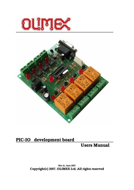
PIC-IO <strong>development</strong> <strong>board</strong>Users ManualRev.A, June 2007Copyright(c) 2007, OLIMEX Ltd, All rights reserved
INTRODUCTION:PIC-IO <strong>board</strong> was designed as simple platform which to allow control ofappliances <strong>and</strong> devices <strong>with</strong> PIC, the idea was to build something liketiny PLC controller which is possible to program in C or assemblerinstead of the weird PLC relay language.Let’s see what we have on <strong>board</strong>:Four High voltage/ High Current <strong>relays</strong> – <strong>with</strong> NO-NC-COM contactsavailable on terminal block. The relay switching current is rated:15A/125VAC, 10A/250VAC, 15A/24VDC. Note that these <strong>relays</strong> aregood for switching resistive loads, but if you have to commutateinductive loads the <strong>relays</strong> will wear off quickly due to the sparkingwhen disconnect the inductive loads (like motors).Each relay have status LED associated <strong>with</strong> it so you can easy seewhich relay is in ON <strong>and</strong> which in OFF state.O1 is connected to RA3 CMP1 <strong>and</strong> PIC CCP module can be used togenerate ON/OFF pulses.O2-O3-O4 are connected to RA2-RA1-RA0.Four <strong>opto</strong>-isolated inputs will allow to detect voltages in range +5-24VDC. Optocouplers are fast <strong>and</strong> switch On/Off for 10 uS, so quicksignals could be detected.I1 is connected to RA4 <strong>and</strong> is good for counting as this pin isconnected to PIC T0CKI.I2 is connected to RB0 which is INT <strong>and</strong> generates interrupts.I3 is connected to CCP1 <strong>and</strong> is good for pulse width measurement.I4 is connected to RB4.The inputs have status LEDs so easy could be seen which input havevoltage. Note that the <strong>opto</strong>couplers inverse the levels i.e. when on theinput have +5V the PIC pin will read “0” <strong>and</strong> vice versa.Status LED is connected to RB5.PIC-IO have RS232 connector, but the driver is made by tricky levelshifter which uses the other side RS232 negative levels to generatethe PIC-IO levels, so on the other side you must have real RS232driver (like PC) if you try to connect two PIC-IO <strong>board</strong>s by RS232 theconnect<strong>io</strong>n will fail as no one of the <strong>board</strong>s will generate the negativelevels.The on-<strong>board</strong> ICSP connector allow you to program the PIC on the<strong>board</strong> <strong>with</strong>out pulling it of the socket, by ICSP programmer like PIC-MCP, PIC-MCP-USB, PIC-PG1, PIC-PG2, PIC-PG3, PIC-PG4 or toprogram <strong>and</strong> debug it <strong>with</strong> PIC-ICD2, PIC-ICD2-POCKET or PIC-ICD2-TINY. IMPORTANT: all programmers provide power supply throughICSP connector during the programming PIC-IO should not be poweredvia the external power jack!The power supply circuit have protect<strong>io</strong>n d<strong>io</strong>de for reverse connect<strong>io</strong>n.The positive point is the internal pin of the power jack. The inputvoltage could be in range 12–14V DC.The oscillator circuit is made <strong>with</strong> 20 Mhz crystal oscillator, so youcan run your PIC at maximum performance.
The RESET is connected <strong>with</strong> 10K to +5V <strong>and</strong> allow safe use of PIC-ICD2 or PIC-MCP programming.
FEATURES:• ICSP/ICD connector for programming <strong>and</strong> debugging• RS232 interface• DIL18 socket• Quartz crystal 20Mhz• LED to RB5 through jumper• Four <strong>opto</strong>-isolated inputs <strong>with</strong> status LEDs• Four Relays 10A/250VAC <strong>with</strong> status LEDs• Power plug-in jack, accept AC <strong>and</strong> DC input• Four mounting holes 3,3 mm (0,13")• FR-4, 1.5 mm (0,062"), green soldermask, white silkscreen component print• Dimens<strong>io</strong>ns 100x80 mm (3,9x3,15")All <strong>board</strong>s produced by Olimex are ROHS compliant
HARDWARE:
SOFTWARE:DEMO1: PIC16F628-I/P CONTROL SOFTWAREThis is demo code, which allow control of the PIC-IO inputs/outputs via PC<strong>with</strong> Hyper terminal.Connect PIC-IO RS232 <strong>with</strong> cable to your PC <strong>and</strong> run Hyper terminal <strong>with</strong>these settings: 9600,8,N,1,NONE. When you apply power this will be seenon the Hyper terminal window:**************************** PIC-IO CONTROL ** (C) 2007, OLIMEX Ltd****************************>_To read the inputs in binary format type “r”, PIC-IO will respond <strong>with</strong>something like:%0000 if all inputs are 0 or%1111 if all inputs are 1 (i.e. +5V is applied)the inputs are <strong>with</strong> right less significant bit i.e. the order is: I4 I3 I2 I1To read the inputs in HEX format type “R”, PIC-IO will respond <strong>with</strong>something like:$0 if all inputs are 0 or$F if all inputs are 1To change the outputs type “w0101”, this will switch on relay 1 <strong>and</strong> relay 3<strong>and</strong> will switch off relay 2 <strong>and</strong> relay 4.If you want to use HEX value you can write “W5” for instance which willswitch on relay 4 <strong>and</strong> relay 1 <strong>and</strong> will switch off relay 2 <strong>and</strong> relay 3.Any other comm<strong>and</strong>s will not be recognized <strong>and</strong> PIC-IO will respond <strong>with</strong>“ERR”
ORDER CODE:PIC-PIO – assembled <strong>and</strong> tested (no kit, no soldering required)How to order?You can order to us directly or by any of our distributors.Check our web www.olimex.com/dev for more info.Revis<strong>io</strong>n history:REV.A - create June 2007
Disclaimer:© 2007 Olimex Ltd. All rights reserved. Olimex®, logo <strong>and</strong> combinat<strong>io</strong>ns thereof, are registered trademarks ofOlimex Ltd. Other terms <strong>and</strong> product names may be trademarks of others.The informat<strong>io</strong>n in this document is provided in connect<strong>io</strong>n <strong>with</strong> Olimex products. No license, express or impliedor otherwise, to any intellectual property right is granted by this document or in connect<strong>io</strong>n <strong>with</strong> the sale of Olimexproducts.Neither the whole nor any part of the informat<strong>io</strong>n contained in or the product described in this document may beadapted or reproduced in any material from except <strong>with</strong> the pr<strong>io</strong>r written permiss<strong>io</strong>n of the copyright holder.The product described in this document is subject to continuous <strong>development</strong> <strong>and</strong> improvements. All particulars ofthe product <strong>and</strong> its use contained in this document are given by OLIMEX in good faith. However all warrantiesimplied or expressed including but not limited to implied warranties of merchantability or fitness for purpose areexcluded.This document is intended only to assist the reader in the use of the product. OLIMEX Ltd. shall not be liable forany loss or damage arising from the use of any informat<strong>io</strong>n in this document or any error or omiss<strong>io</strong>n in suchinformat<strong>io</strong>n or any incorrect use of the product.