7130 Oil Burner Controls LMO14... LMO24... LMO44... - Romstal
7130 Oil Burner Controls LMO14... LMO24... LMO44... - Romstal
7130 Oil Burner Controls LMO14... LMO24... LMO44... - Romstal
- No tags were found...

Create successful ePaper yourself
Turn your PDF publications into a flip-book with our unique Google optimized e-Paper software.
Commissioning notes• When commissioning the plant or when doing maintenance work, make the followingsafety checks:Safety checka) <strong>Burner</strong> startup with flame detector darkenedb) <strong>Burner</strong> startup with flame detector exposedto extraneous lightc) <strong>Burner</strong> operation with simulated loss offlame; for that purpose, darken the flamedetector during operation and maintainthat stateAnticipated responseLockout at the end of «TSA»Lockout after no more than 40secondsRepetition followed by lockout atthe end of «TSA»Standards and certificatesConformity to EEC directives- Electromagnetic compatibility EMC (immunity)- Low-voltage directive2004/108/EC2006/95/ECISO 9001: 2000Cert. 00739ISO 14001: 2004Cert. 38233Type Identification code to EN 230:<strong>LMO14.</strong>..F M L L X N<strong>LMO24.</strong>..F M L L X N<strong>LMO44.</strong>..F M L L X N to WLEService notes• Use the KF8885 / KF8833 / KF8840 service adapters for short periods of time onlyLife cycle<strong>Burner</strong> controls has a designed lifetime* of 250,000 burner startup cycles which, undernormal operating conditions in heating mode, correspond to approx. 10 years of usage(starting from the production date given on the type field). This lifetime is based on theendurance tests specified in standard EN230 and the table containing the relevant testdocumentation as published by the European Association of Component Manufacturers(Afecor) (www.afecor.org).The designed lifetime is based on use of the burner controls according to the manufacturer’sData Sheet. After reaching the designed lifetime in terms of the number ofburner startup cycles, or the respective time of usage, the burner control is to be replacedby authorized personnel.* The designed lifetime is not the warranty time specified in the Terms of DeliveryDisposal notesThe unit contains electrical and electronic components and must not be disposed of togetherwith domestic waste.Local and currently valid legislation must be observed.3/13Building TechnologiesCC1N<strong>7130</strong>enHVAC Products 15.09.2008
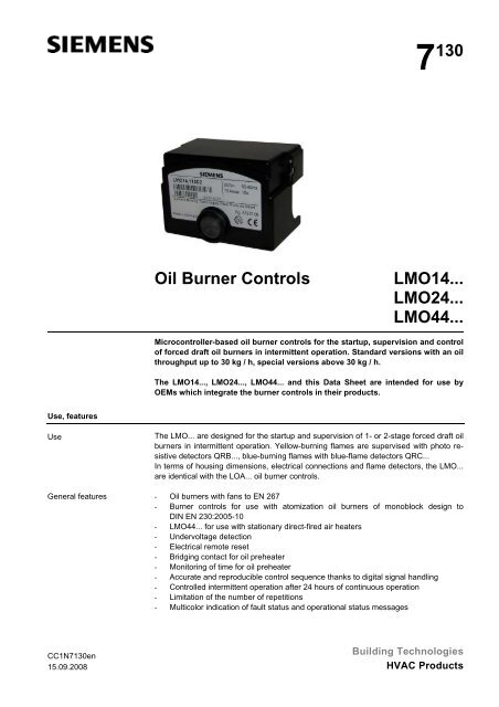
Technical dataGeneral unit dataMains voltage AC 230 V +10 % / -15 %AC 120 V +10 % / -15 %Mains frequency 50...60 Hz ±6 %External primary fuse (Si)6.3 A (slow)Power consumption12 VAPerm. mounting orientationOptionalWeightApprox. 200 gSafety classI (burner control with plug-in base)Degree of protectionIP40 (to be ensured through mounting)Perm. cable lengthsMax. 3 m at a line capacitance of 100 pF/mDetector cable laid separately10 mRemote reset laid separately20 mPerm. current at cosϕ ≥ 0.6 <strong>LMO14.</strong>.. <strong>LMO24.</strong>.. <strong>LMO44.</strong>..Terminal 1 Max. 5 A Max. 5 A Max. 5 ATerminals 3 and 8 Max. 3 A Max. 5 A Max. 5 ATerminals 4 and 5 Max. 1 A Max. 1 A Max. 1 ATerminal 6 Max. 1 A Max. 1 A Max. 2 ATerminal 10 Max. 1 A Max. 1 A Max. 1 AEnvironmentalconditionsStorage DIN EN 60721-3-1Climatic conditionsClass 1K3Mechanical conditionsClass 1M2Temperature range -20...+60 °CHumidity
Technical data (cont´d)Flame supervision withQRB... or QRC...Green LED for operationalstatus indicationDetector currentrequired(with flame)Perm. detectorcurrent(without flame)Possible detector currentwith flame(typically)QRB... ¹) Min. 45 µA Max. 5.5 µA Max. 100 µAQRC... ¹) Min. 70 µA Max. 5.5 µA Max. 100 µADetector current in operation:- Flame signal instable- Green LED flashingDetector current in operation:- Flame signal stable- Green LED steady onQRB... ¹) 45 µAQRC... ¹) 45 µA¹) The values given in the table above only apply under the following conditions:- Mains voltage depending on execution AC 120 V or AC 230 V- Ambient temperature 23 °CMeasuring circuitfor detector currentQRB...11 12 LMO...<strong>7130</strong>v01/0700blsw+QRB...µA DCQRC...11 12 1 LMO...<strong>7130</strong>v02/0700bl sw br+QRC1...µA DCLegendµA DC DC microammeterwith an internalresistance ofRi = max. 5 kΩbl Bluesw Blackbr BrownAs an alternative to detector current measurement, the diagnostic tool OCI400 / withPC software ACS400 / ACS410 can be used. In that case, the DC microammeter is notrequired.7/13Building TechnologiesCC1N<strong>7130</strong>enHVAC Products 15.09.2008
FunctionPreconditions forstartupUndervoltageTime supervisionoil preheaterControlled intermittentoperationControl sequence inthe event of fault• <strong>Burner</strong> control is reset• Reset button «EK1» or «EK2» not used• All contacts in the line are closed and there is demand for heat• No undervoltage• Flame detector is darkened and there is no extraneous light• Safety shutdown from the operating position takes place should mains voltage dropbelow about AC 165 V (UN = AC 230 V) or AC 75 V (UN = AC 120 V)• Restart is initiated when mains voltage exceeds about AC 175 V (UN = AC 230 V)or AC 95 V (UN = AC 120 V)If the oil preheater’s release contact does not close within 10 minutes, the burner controlwill initiate lockout.After no more than 24 hours of continuous operation, the burner control will initiateautomatic controlled shutdown followed by a restart.If lockout occurs, the outputs for the fuel valves, the burner motor and the ignition equipmentwill immediately be deactivated (
Operation, display, diagnosticsOperationEK<strong>7130</strong>z05/0700Lockout reset button «EK» is the key operating element for resettingthe burner control and for activating / deactivating the diagnostic functions.<strong>7130</strong>z06e/0700RedYellowGreenLEDThe multicolor signal lamp (LED) in the lockout reset button is the keyindicating element for both visual diagnostics and interface diagnostics.Both «EK» and LED are located under the transparent cover of the lockout reset button.There are 2 diagnostic choices:1. Visual diagnostics: Operational status indication or diagnostics of the cause offault.2. Interface diagnostics: With the help of the interface adapter OCI400 and PC softwareACS400 / ACS410 or flue gas analyzers of different makes.Visual diagnostics:In normal operation, the different operating states are indicated in the form of colorcodes according to the color code table given below.Operational statusindicationLegendDuring startup, status indication takes place according to the following table:Color code table for multicolor signal lamp (LED)Status Color code ColorWaiting time «tw», other waiting states ........................................ Off<strong>Oil</strong> preheater on •........................................ YellowIgnition phase, ignition controlled • • • • • • Flashing yellowOperation, flame o.k. ........................................ GreenOperation, flame not o.k. Flashing greenExtraneous light on burner startup Green-redUndervoltage • • • • • Yellow-redFault, alarm ....................................... RedError code output (refer to «Error code table») Flashing redInterface diagnostics Red flicker light...... Steady on Red Off • Yellow Green9/13Building TechnologiesCC1N<strong>7130</strong>enHVAC Products 15.09.2008
Operation, display, diagnostics (cont´d)Diagnostics of thecause of faultAfter lockout, the red fault signal lamp remains steady on. In that condition, the visualdiagnostics of the cause of fault according to the error code table can be activated bypressing the lockout reset button for more than 3 seconds. Pressing the reset buttonagain for at least 3 seconds, the interface diagnostics will be activated. Interface diagnosticsworks only if the AGK20… lockout reset button extension is not fitted. If, by accident,interface diagnostics has been activated, in which case the slightly red light ofthe signal lamp flickers, it can be deactivated by pressing again the lockout reset buttonfor at least 3 seconds. The instant of switching over is indicated by a yellow light pulse.The following sequence activates the diagnostics of the cause of fault:OCI400Lockout position Lockout position Lockout positionVisual diagnosticsInterface diagnosticsOnFlashingPC / analyzerEK> 3 sError code tablexxxxxxxxxxxxxxxxxxxxxxxxxxxxxxxxxxxxxxxxxxxxxxxxEK> 3 s<strong>7130</strong>z04e/0602EK< 3 sResetError code tableRed blink code of signal «AL» at Possible causelamp (LED)term. 102 blinks On No establishment of flame at the end of «TSA»- Faulty or soiled fuel valves- Faulty or soiled flame detector- Poor adjustment of burner, no fuel- Faulty ignition equipment3 blinks On Free4 blinks On Extraneous light on burner startup5 blinks On Free6 blinks On Free7 blinks On Too many losses of flame during operation (limitationof the number of repetitions)- Faulty or soiled fuel valves- Faulty or soiled flame detector- Poor adjustment of burner8 blinks On Time supervision oil preheater9 blinks On Free10 blinks Off Wiring fault or internal fault, output contacts, o-ther faultsDuring the time the cause of fault is diagnosed, the control outputs are deactivated burnerremains shut down.The diagnostics of the cause of fault is quit and the burner switched on again by resettingthe burner control. Press the lockout reset button for about 1 second (
LegendALBV...EK1EK2FSFSVK...kbrLEDMOWOHQRB...QRC...RSBSiWZAlarm deviceFuel valveLockout reset buttonRemote lockout reset buttonFlame signalFlame signal amplifierContacts of control relayCable link (required only when no oil preheater is used)3-color signal lamp<strong>Burner</strong> motorRelease contact of oil preheater<strong>Oil</strong> preheaterPhoto resistive flame detectorBlue-flame detectorbl = blue, br = brown, sw = blackControl thermostat or pressurestatSafety limit thermostatExternal primary fuseLimit thermostat or pressure switchIgnition transformerTSA Ignition safety timetwWaiting timet1Prepurge timet1´ Purge timet3Preignition timet3nPostignition timet4Interval from flame signal to release of «BV2»A´ Start of startup sequence with burners using an «OH»AStart of startup sequence with burners using no «OH»BTime of flame establishmentCOperating positionDControlled shutdown by «R»Control signalsRequired input signalsPerm. input signalsµC1 Microcontroller 1µC2 Microcontroller 212/13Building TechnologiesCC1N<strong>7130</strong>enHVAC Products 15.09.2008
DimensionsDimensions in mmLMO...225,253,9889141,6<strong>7130</strong>m05/090447,262,5<strong>7130</strong>m04/1004Plug-in base AGK11... / AGK13...9LMO... with extension oflockout reset buttonAGK20...7,44 LType reference Length «L» in mmAGK20.20 19AGK20.43 43AGK20.55 55© 2008 Siemens Building Technologies HVAC Products GmbHSubject to change!13/13Building TechnologiesCC1N<strong>7130</strong>enHVAC Products 15.09.2008