LM35 Precision Centigrade Temperature Sensors - 320Volt
LM35 Precision Centigrade Temperature Sensors - 320Volt
LM35 Precision Centigrade Temperature Sensors - 320Volt

You also want an ePaper? Increase the reach of your titles
YUMPU automatically turns print PDFs into web optimized ePapers that Google loves.
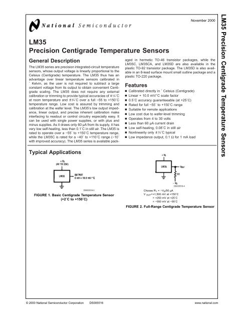
<strong>LM35</strong><strong>Precision</strong> <strong>Centigrade</strong> <strong>Temperature</strong> <strong>Sensors</strong>General DescriptionTypical ApplicationsThe <strong>LM35</strong> series are precision integrated-circuit temperaturesensors, whose output voltage is linearly proportional to theCelsius (<strong>Centigrade</strong>) temperature. The <strong>LM35</strong> thus has anadvantage over linear temperature sensors calibrated in˚ Kelvin, as the user is not required to subtract a largeconstant voltage from its output to obtain convenient <strong>Centigrade</strong>scaling. The <strong>LM35</strong> does not require any externalcalibration or trimming to provide typical accuracies of ± 1 ⁄4˚Cat room temperature and ± 3 ⁄4˚C over a full −55 to +150˚Ctemperature range. Low cost is assured by trimming andcalibration at the wafer level. The <strong>LM35</strong>’s low output impedance,linear output, and precise inherent calibration makeinterfacing to readout or control circuitry especially easy. Itcan be used with single power supplies, or with plus andminus supplies. As it draws only 60 µA from its supply, it hasvery low self-heating, less than 0.1˚C in still air. The <strong>LM35</strong> israted to operate over a −55˚ to +150˚C temperature range,while the <strong>LM35</strong>C is rated for a −40˚ to +110˚C range (−10˚with improved accuracy). The <strong>LM35</strong> series is available packagedin hermetic TO-46 transistor packages, while the<strong>LM35</strong>C, <strong>LM35</strong>CA, and <strong>LM35</strong>D are also available in theplastic TO-92 transistor package. The <strong>LM35</strong>D is also availablein an 8-lead surface mount small outline package and aplastic TO-220 package.Featuresn Calibrated directly in ˚ Celsius (<strong>Centigrade</strong>)n Linear + 10.0 mV/˚C scale factorn 0.5˚C accuracy guaranteeable (at +25˚C)n Rated for full −55˚ to +150˚C rangen Suitable for remote applicationsn Low cost due to wafer-level trimmingn Operates from 4 to 30 voltsn Less than 60 µA current drainn Low self-heating, 0.08˚C in still airn Nonlinearity only ± 1 ⁄4˚C typicaln Low impedance output, 0.1 Ω for 1 mA loadNovember 2000<strong>LM35</strong> <strong>Precision</strong> <strong>Centigrade</strong> <strong>Temperature</strong> <strong>Sensors</strong>DS005516-3FIGURE 1. Basic <strong>Centigrade</strong> <strong>Temperature</strong> Sensor(+2˚C to +150˚C)DS005516-4Choose R 1 =−V S /50 µAV OUT =+1,500 mV at +150˚C= +250 mV at +25˚C= −550 mV at −55˚CFIGURE 2. Full-Range <strong>Centigrade</strong> <strong>Temperature</strong> Sensor© 2000 National Semiconductor Corporation DS005516 www.national.com
<strong>LM35</strong>Connection DiagramsTO-46Metal Can Package*SO-8Small Outline Molded Package*Case is connected to negative pin (GND)DS005516-1Order Number <strong>LM35</strong>H, <strong>LM35</strong>AH, <strong>LM35</strong>CH, <strong>LM35</strong>CAH or<strong>LM35</strong>DHSee NS Package Number H03HN.C. = No ConnectionDS005516-21Top ViewOrder Number <strong>LM35</strong>DMSee NS Package Number M08ATO-92Plastic PackageTO-220Plastic Package*DS005516-2Order Number <strong>LM35</strong>CZ,<strong>LM35</strong>CAZ or <strong>LM35</strong>DZSee NS Package Number Z03ADS005516-24*Tab is connected to the negative pin (GND).Note: The <strong>LM35</strong>DT pinout is different than the discontinued <strong>LM35</strong>DP.Order Number <strong>LM35</strong>DTSee NS Package Number TA03Fwww.national.com 2
Absolute Maximum Ratings (Note 10)If Military/Aerospace specified devices are required,please contact the National Semiconductor Sales Office/Distributors for availability and specifications.Supply VoltageOutput VoltageOutput CurrentStorage Temp.;TO-46 Package,TO-92 Package,SO-8 Package,TO-220 Package,Lead Temp.:TO-46 Package,(Soldering, 10 seconds)Electrical Characteristics(Notes 1, 6)+35V to −0.2V+6V to −1.0V10 mA−60˚C to +180˚C−60˚C to +150˚C−65˚C to +150˚C−65˚C to +150˚C300˚CTO-92 and TO-220 Package,(Soldering, 10 seconds)260˚CSO Package (Note 12)Vapor Phase (60 seconds)215˚CInfrared (15 seconds)220˚CESD Susceptibility (Note 11)2500VSpecified Operating <strong>Temperature</strong> Range: T MIN to T MAX(Note 2)<strong>LM35</strong>, <strong>LM35</strong>A−55˚C to +150˚C<strong>LM35</strong>C, <strong>LM35</strong>CA−40˚C to +110˚C<strong>LM35</strong>D0˚C to +100˚C<strong>LM35</strong><strong>LM35</strong>A<strong>LM35</strong>CAParameter Conditions Tested Design Tested Design UnitsTypical Limit Limit Typical Limit Limit (Max.)(Note 4) (Note 5) (Note 4) (Note 5)Accuracy T A =+25˚C ±0.2 ±0.5 ±0.2 ±0.5 ˚C(Note 7) T A =−10˚C ±0.3 ±0.3 ±1.0 ˚CT A =T MAX±0.4 ±1.0 ±0.4 ±1.0 ˚CT A =T MIN±0.4 ±1.0 ±0.4 ±1.5 ˚CNonlinearity T MIN ≤T A ≤T MAX±0.18 ±0.35 ±0.15 ±0.3 ˚C(Note 8)Sensor Gain T MIN ≤T A ≤T MAX +10.0 +9.9, +10.0 +9.9, mV/˚C(Average Slope) +10.1 +10.1Load Regulation T A =+25˚C ±0.4 ±1.0 ±0.4 ±1.0 mV/mA(Note 3) 0≤I L ≤1mA T MIN ≤T A ≤T MAX±0.5 ±3.0 ±0.5 ±3.0 mV/mALine Regulation T A =+25˚C ±0.01 ±0.05 ±0.01 ±0.05 mV/V(Note 3) 4V≤V S ≤30V ±0.02 ±0.1 ±0.02 ±0.1 mV/VQuiescent Current V S =+5V, +25˚C 56 67 56 67 µA(Note 9) V S =+5V 105 131 91 114 µAV S =+30V, +25˚C 56.2 68 56.2 68 µAV S =+30V 105.5 133 91.5 116 µAChange of 4V≤V S ≤30V, +25˚C 0.2 1.0 0.2 1.0 µAQuiescent Current 4V≤V S ≤30V 0.5 2.0 0.5 2.0 µA(Note 3)<strong>Temperature</strong> +0.39 +0.5 +0.39 +0.5 µA/˚CCoefficient ofQuiescent CurrentMinimum <strong>Temperature</strong> In circuit of +1.5 +2.0 +1.5 +2.0 ˚Cfor Rated Accuracy Figure 1, I L =0Long Term Stability T J =T MAX , for ±0.08 ±0.08 ˚C1000 hours3www.national.com
<strong>LM35</strong>Electrical Characteristics(Notes 1, 6)<strong>LM35</strong><strong>LM35</strong>C, <strong>LM35</strong>DParameter Conditions Tested Design Tested Design UnitsTypical Limit Limit Typical Limit Limit (Max.)(Note 4) (Note 5) (Note 4) (Note 5)Accuracy, T A =+25˚C ±0.4 ±1.0 ±0.4 ±1.0 ˚C<strong>LM35</strong>, <strong>LM35</strong>C T A =−10˚C ±0.5 ±0.5 ±1.5 ˚C(Note 7) T A =T MAX±0.8 ±1.5 ±0.8 ±1.5 ˚CT A =T MIN±0.8 ±1.5 ±0.8 ±2.0 ˚CAccuracy, <strong>LM35</strong>D T A =+25˚C ±0.6 ±1.5 ˚C(Note 7)T A =T MAX±0.9 ±2.0 ˚CT A =T MIN±0.9 ±2.0 ˚CNonlinearity T MIN ≤T A ≤T MAX±0.3 ±0.5 ±0.2 ±0.5 ˚C(Note 8)Sensor Gain T MIN ≤T A ≤T MAX +10.0 +9.8, +10.0 +9.8, mV/˚C(Average Slope) +10.2 +10.2Load Regulation T A =+25˚C ±0.4 ±2.0 ±0.4 ±2.0 mV/mA(Note 3) 0≤I L ≤1mA T MIN ≤T A ≤T MAX±0.5 ±5.0 ±0.5 ±5.0 mV/mALine Regulation T A =+25˚C ±0.01 ±0.1 ±0.01 ±0.1 mV/V(Note 3) 4V≤V S ≤30V ±0.02 ±0.2 ±0.02 ±0.2 mV/VQuiescent Current V S =+5V, +25˚C 56 80 56 80 µA(Note 9) V S =+5V 105 158 91 138 µAV S =+30V, +25˚C 56.2 82 56.2 82 µAV S =+30V 105.5 161 91.5 141 µAChange of 4V≤V S ≤30V, +25˚C 0.2 2.0 0.2 2.0 µAQuiescent Current 4V≤V S ≤30V 0.5 3.0 0.5 3.0 µA(Note 3)<strong>Temperature</strong> +0.39 +0.7 +0.39 +0.7 µA/˚CCoefficient ofQuiescent CurrentMinimum <strong>Temperature</strong> In circuit of +1.5 +2.0 +1.5 +2.0 ˚Cfor Rated Accuracy Figure 1, I L =0Long Term Stability T J =T MAX , for ±0.08 ±0.08 ˚C1000 hoursNote 1: Unless otherwise noted, these specifications apply: −55˚C≤T J ≤+150˚C for the <strong>LM35</strong> and <strong>LM35</strong>A; −40˚≤T J ≤+110˚C for the <strong>LM35</strong>C and <strong>LM35</strong>CA; and0˚≤T J ≤+100˚C for the <strong>LM35</strong>D. V S =+5Vdc and I LOAD =50 µA, in the circuit of Figure 2. These specifications also apply from +2˚C to T MAX in the circuit of Figure 1.Specifications in boldface apply over the full rated temperature range.Note 2: Thermal resistance of the TO-46 package is 400˚C/W, junction to ambient, and 24˚C/W junction to case. Thermal resistance of the TO-92 package is180˚C/W junction to ambient. Thermal resistance of the small outline molded package is 220˚C/W junction to ambient. Thermal resistance of the TO-220 packageis 90˚C/W junction to ambient. For additional thermal resistance information see table in the Applications section.Note 3: Regulation is measured at constant junction temperature, using pulse testing with a low duty cycle. Changes in output due to heating effects can becomputed by multiplying the internal dissipation by the thermal resistance.Note 4: Tested Limits are guaranteed and 100% tested in production.Note 5: Design Limits are guaranteed (but not 100% production tested) over the indicated temperature and supply voltage ranges. These limits are not used tocalculate outgoing quality levels.Note 6: Specifications in boldface apply over the full rated temperature range.Note 7: Accuracy is defined as the error between the output voltage and 10mv/˚C times the device’s case temperature, at specified conditions of voltage, current,and temperature (expressed in ˚C).Note 8: Nonlinearity is defined as the deviation of the output-voltage-versus-temperature curve from the best-fit straight line, over the device’s rated temperaturerange.Note 9: Quiescent current is defined in the circuit of Figure 1.Note 10: Absolute Maximum Ratings indicate limits beyond which damage to the device may occur. DC and AC electrical specifications do not apply when operatingthe device beyond its rated operating conditions. See Note 1.Note 11: Human body model, 100 pF discharged through a 1.5 kΩ resistor.Note 12: See AN-450 “Surface Mounting Methods and Their Effect on Product Reliability” or the section titled “Surface Mount” found in a current NationalSemiconductor Linear Data Book for other methods of soldering surface mount devices.www.national.com 4
Typical Performance Characteristics<strong>LM35</strong>Thermal ResistanceJunction to AirThermal Time ConstantThermal Responsein Still AirDS005516-25DS005516-26DS005516-27Thermal Response inStirred Oil BathMinimum SupplyVoltage vs. <strong>Temperature</strong>Quiescent Currentvs. <strong>Temperature</strong>(In Circuit of Figure 1.)DS005516-28DS005516-29DS005516-30Quiescent Currentvs. <strong>Temperature</strong>(In Circuit of Figure 2.)Accuracy vs. <strong>Temperature</strong>(Guaranteed)Accuracy vs. <strong>Temperature</strong>(Guaranteed)DS005516-31DS005516-32DS005516-335www.national.com
<strong>LM35</strong>Typical Performance Characteristics (Continued)Noise VoltageStart-Up ResponseApplicationsDS005516-34The <strong>LM35</strong> can be applied easily in the same way as otherintegrated-circuit temperature sensors. It can be glued orcemented to a surface and its temperature will be withinabout 0.01˚C of the surface temperature.This presumes that the ambient air temperature is almost thesame as the surface temperature; if the air temperature weremuch higher or lower than the surface temperature, theactual temperature of the <strong>LM35</strong> die would be at an intermediatetemperature between the surface temperature and theair temperature. This is expecially true for the TO-92 plasticpackage, where the copper leads are the principal thermalpath to carry heat into the device, so its temperature mightbe closer to the air temperature than to the surface temperature.To minimize this problem, be sure that the wiring to the<strong>LM35</strong>, as it leaves the device, is held at the same temperatureas the surface of interest. The easiest way to do this isto cover up these wires with a bead of epoxy which willinsure that the leads and wires are all at the same temperatureas the surface, and that the <strong>LM35</strong> die’s temperature willnot be affected by the air temperature.The TO-46 metal package can also be soldered to a metalsurface or pipe without damage. Of course, in that case theV− terminal of the circuit will be grounded to that metal.Alternatively, the <strong>LM35</strong> can be mounted inside a sealed-endmetal tube, and can then be dipped into a bath or screwedinto a threaded hole in a tank. As with any IC, the <strong>LM35</strong> andaccompanying wiring and circuits must be kept insulated anddry, to avoid leakage and corrosion. This is especially true ifthe circuit may operate at cold temperatures where condensationcan occur. Printed-circuit coatings and varnishes suchas Humiseal and epoxy paints or dips are often used toinsure that moisture cannot corrode the <strong>LM35</strong> or its connections.These devices are sometimes soldered to a smalllight-weight heat fin, to decrease the thermal time constantand speed up the response in slowly-moving air. On theother hand, a small thermal mass may be added to thesensor, to give the steadiest reading despite small deviationsin the air temperature.<strong>Temperature</strong> Rise of <strong>LM35</strong> Due To Self-heating (Thermal Resistance,θ JA )TO-46, TO-46*, TO-92, TO-92**, SO-8 SO-8** TO-220no heatsinksmall heat fin no heatsinksmall heat fin no heatsinksmall heat fin no heatsinkStill air 400˚C/W 100˚C/W 180˚C/W 140˚C/W 220˚C/W 110˚C/W 90˚C/WMoving air 100˚C/W 40˚C/W 90˚C/W 70˚C/W 105˚C/W 90˚C/W 26˚C/WStill oil 100˚C/W 40˚C/W 90˚C/W 70˚C/WStirred oil 50˚C/W 30˚C/W 45˚C/W 40˚C/W(Clamped to metal,Infinite heat sink) (24˚C/W) (55˚C/W)*Wakefield type 201, or 1" disc of 0.020" sheet brass, soldered to case, or similar.**TO-92 and SO-8 packages glued and leads soldered to 1" square of 1/16" printed circuit board with 2 oz. foil or similar.DS005516-35www.national.com 6
Typical Applications<strong>LM35</strong>DS005516-19FIGURE 3. <strong>LM35</strong> with Decoupling from Capacitive LoadDS005516-6FIGURE 6. Two-Wire Remote <strong>Temperature</strong> Sensor(Output Referred to Ground)FIGURE 4. <strong>LM35</strong> with R-C DamperDS005516-20CAPACITIVE LOADSLike most micropower circuits, the <strong>LM35</strong> has a limited abilityto drive heavy capacitive loads. The <strong>LM35</strong> by itself is able todrive 50 pf without special precautions. If heavier loads areanticipated, it is easy to isolate or decouple the load with aresistor; see Figure 3. Or you can improve the tolerance ofcapacitance with a series R-C damper from output toground; see Figure 4.When the <strong>LM35</strong> is applied with a 200Ω load resistor asshown in Figure 5, Figure 6 or Figure 8 it is relatively immuneto wiring capacitance because the capacitance forms a bypassfrom ground to input, not on the output. However, aswith any linear circuit connected to wires in a hostile environment,its performance can be affected adversely by intenseelectromagnetic sources such as relays, radio transmitters,motors with arcing brushes, SCR transients, etc, asits wiring can act as a receiving antenna and its internaljunctions can act as rectifiers. For best results in such cases,a bypass capacitor from V IN to ground and a series R-Cdamper such as 75Ω in series with 0.2 or 1 µF from output toground are often useful. These are shown in Figure 13,Figure 14, and Figure 16.DS005516-7FIGURE 7. <strong>Temperature</strong> Sensor, Single Supply, −55˚ to+150˚CFIGURE 8. Two-Wire Remote <strong>Temperature</strong> Sensor(Output Referred to Ground)DS005516-8DS005516-5FIGURE 5. Two-Wire Remote <strong>Temperature</strong> Sensor(Grounded Sensor)DS005516-9FIGURE 9. 4-To-20 mA Current Source (0˚C to +100˚C)7www.national.com
<strong>LM35</strong>Typical Applications (Continued)DS005516-11FIGURE 11. <strong>Centigrade</strong> Thermometer (Analog Meter)DS005516-10FIGURE 10. Fahrenheit ThermometerDS005516-12FIGURE 12. Fahrenheit ThermometerExpanded ScaleThermometer(50˚ to 80˚ Fahrenheit, for Example Shown)DS005516-13FIGURE 13. <strong>Temperature</strong> To Digital Converter (Serial Output) (+128˚C Full Scale)DS005516-14FIGURE 14. <strong>Temperature</strong> To Digital Converter (Parallel TRI-STATE Outputs forStandard Data Bus to µP Interface) (128˚C Full Scale)www.national.com 8
Typical Applications (Continued)<strong>LM35</strong>*=1% or 2% film resistorTrim R B for V B =3.075VTrim R C for V C =1.955VTrim R A for V A =0.075V + 100mV/˚C x T ambientExample, V A =2.275V at 22˚CFIGURE 15. Bar-Graph <strong>Temperature</strong> Display (Dot Mode)DS005516-16DS005516-15FIGURE 16. <strong>LM35</strong> With Voltage-To-Frequency Converter And Isolated Output(2˚C to +150˚C; 20 Hz to 1500 Hz)9www.national.com
<strong>LM35</strong>Block DiagramDS005516-23www.national.com 10