DCI Specs - Digital Cinema Initiatives
DCI Specs - Digital Cinema Initiatives
DCI Specs - Digital Cinema Initiatives

Create successful ePaper yourself
Turn your PDF publications into a flip-book with our unique Google optimized e-Paper software.
<strong>Digital</strong> <strong>Cinema</strong> <strong>Initiatives</strong>, LLC<strong>Digital</strong> <strong>Cinema</strong> System SpecificationVersion 1.2March 07, 2008Approval March 07, 2008<strong>Digital</strong> <strong>Cinema</strong> <strong>Initiatives</strong>, LLC, Member Representatives CommitteeCopyright © 2005-2008<strong>Digital</strong> <strong>Cinema</strong> <strong>Initiatives</strong>, LLC<strong>DCI</strong> <strong>Digital</strong> <strong>Cinema</strong> System Specification v.1.2 Page 1
NOTICE<strong>Digital</strong> <strong>Cinema</strong> <strong>Initiatives</strong>, LLC (<strong>DCI</strong>) is the author and creator of this specification for the purposeof copyright and other laws in all countries throughout the world. The <strong>DCI</strong> copyright notice must beincluded in all reproductions, whether in whole or in part, and may not be deleted or attributed to others.<strong>DCI</strong> hereby grants to its members and their suppliers a limited license to reproduce this specification fortheir own use, provided it is not sold. Others should obtain permission to reproduce this specification from<strong>Digital</strong> <strong>Cinema</strong> <strong>Initiatives</strong>, LLC.This document is a specification developed and adopted by <strong>Digital</strong> <strong>Cinema</strong> <strong>Initiatives</strong>, LLC. Thisdocument may be revised by <strong>DCI</strong>. It is intended solely as a guide for companies interested in developingproducts, which can be compatible with other products, developed using this document. Each <strong>DCI</strong>member company shall decide independently the extent to which it will utilize, or require adherence to,these specifications. <strong>DCI</strong> shall not be liable for any exemplary, incidental, proximate or consequentialdamages or expenses arising from the use of this document. This document defines only one approach tocompatibility, and other approaches may be available to the industry.This document is an authorized and approved publication of <strong>DCI</strong>. Only <strong>DCI</strong> has the right andauthority to revise or change the material contained in this document, and any revisions by any partyother than <strong>DCI</strong> are unauthorized and prohibited.Compliance with this document may require use of one or more features covered by proprietaryrights (such as features which are the subject of a patent, patent application, copyright, mask work rightor trade secret right). By publication of this document, no position is taken by <strong>DCI</strong> with respect to thevalidity or infringement of any patent or other proprietary right. <strong>DCI</strong> hereby expressly disclaims any liabilityfor infringement of intellectual property rights of others by virtue of the use of this document. <strong>DCI</strong> has notand does not investigate any notices or allegations of infringement prompted by publication of any <strong>DCI</strong>document, nor does <strong>DCI</strong> undertake a duty to advise users or potential users of <strong>DCI</strong> documents of suchnotices or allegations. <strong>DCI</strong> hereby expressly advises all users or potential users of this document toinvestigate and analyze any potential infringement situation, seek the advice of intellectual propertycounsel, and, if indicated, obtain a license under any applicable intellectual property right or take thenecessary steps to avoid infringement of any intellectual property right. <strong>DCI</strong> expressly disclaims any intentto promote infringement of any intellectual property right by virtue of the evolution, adoption, or publicationof this document.<strong>DCI</strong> <strong>Digital</strong> <strong>Cinema</strong> System Specification v.1.2 Page 2
Table of Contents1. OVERVIEW 151.1. Introduction ...................................................................................................................151.2. Scope ............................................................................................................................. 151.3. Document Language..................................................................................................... 161.4. System Objectives ........................................................................................................ 172. SYSTEM OVERVIEW 192.1. Functional Framework.................................................................................................. 192.1.1. Major System Concepts....................................................................................... 222.1.1.1. <strong>Digital</strong> Source Master (DSM)......................................................................... 222.1.1.2. Composition................................................................................................... 222.1.1.3. <strong>Digital</strong> <strong>Cinema</strong> Distribution Master (DCDM) .................................................. 222.1.1.4. <strong>Digital</strong> <strong>Cinema</strong> Package (DCP) ..................................................................... 222.1.1.5. Hierarchical Image Structure ......................................................................... 232.1.1.6. File / Frame-Based System ........................................................................... 232.1.1.7. Store and Forward......................................................................................... 232.1.1.8. Reels ............................................................................................................. 242.1.1.9. Component Design........................................................................................ 242.1.1.10. Storage and Media Block .............................................................................. 243. DIGITAL CINEMA DISTRIBUTION MASTER 253.1. Overview ........................................................................................................................253.1.1. Introduction .......................................................................................................... 253.1.2. DCDM System Overview...................................................................................... 253.1.3. Major DCDM Concepts......................................................................................... 253.1.4. DCDM Fundamental Requirements .................................................................... 263.1.4.1. Common File Formats ................................................................................... 263.1.4.2. Frame Rates.................................................................................................. 263.1.4.3. Synchronization ............................................................................................. 263.2. Image Specification ...................................................................................................... 263.2.1. Image Concepts and Requirements ................................................................... 263.2.1.1. Introduction.................................................................................................... 263.2.1.2. Image Structure ............................................................................................. 263.2.1.3. Center of Image............................................................................................. 273.2.1.4. Colorimetry .................................................................................................... 273.2.1.5. Encoding Primaries ....................................................................................... 273.2.1.6. Transfer Function .......................................................................................... 283.2.1.7. Bit Depth........................................................................................................ 283.2.1.8. Aspect Ratio .................................................................................................. 283.2.2. DCDM Image File Format..................................................................................... 293.2.2.1. Introduction.................................................................................................... 293.2.2.2. File Mapping .................................................................................................. 293.2.2.3. Synchronization ............................................................................................. 29<strong>DCI</strong> <strong>Digital</strong> <strong>Cinema</strong> System Specification v.1.2 Page 3
3.2.2.4. Image Metadata Required Fields .................................................................. 293.3. Audio Specification....................................................................................................... 303.3.1. Audio Concepts and Requirements ................................................................... 303.3.2. Audio Characteristics .......................................................................................... 303.3.2.1. Introduction.................................................................................................... 303.3.2.2. Bit Depth........................................................................................................ 303.3.2.3. Sample Rate.................................................................................................. 303.3.2.4. Channel Count............................................................................................... 303.3.2.5. <strong>Digital</strong> Reference Level ................................................................................. 303.3.3. Channel Mapping ................................................................................................. 313.3.4. File Format............................................................................................................ 343.3.4.1. General.......................................................................................................... 343.3.4.2. Synchronization ............................................................................................. 343.4. Text Rendering .............................................................................................................. 343.4.1. Text Rendering Concepts and Requirements ................................................... 343.4.2. Subpicture............................................................................................................. 353.4.2.1. Introduction.................................................................................................... 353.4.2.2. File Format .................................................................................................... 353.4.2.3. Rendering Intent ............................................................................................ 353.4.2.4. Frame Rate and Timing................................................................................. 353.4.2.5. Synchronization ............................................................................................. 353.4.3. Timed Text Concepts and Requirements........................................................... 363.4.3.1. Introduction.................................................................................................... 363.4.3.2. File Format .................................................................................................... 363.4.3.3. Restart ........................................................................................................... 363.4.3.4. Default Font ................................................................................................... 363.4.3.5. Identification .................................................................................................. 363.4.3.6. Searchability .................................................................................................. 363.4.3.7. Multiple Captions ........................................................................................... 363.4.3.8. Synchronization ............................................................................................. 373.4.4. Show Control Concepts and Requirements ...................................................... 373.4.5. Show Controls...................................................................................................... 373.4.5.1. Introduction.................................................................................................... 374. COMPRESSION 394.1. Introduction ...................................................................................................................394.2. Compression Standard................................................................................................. 394.3. Decoder Specification .................................................................................................. 394.3.1. Definitions............................................................................................................. 394.3.2. Decoder Requirements........................................................................................ 394.4. Codestream Specification ............................................................................................ 405. PACKAGING 435.1. Introduction ...................................................................................................................435.2. Packaging System Overview ....................................................................................... 435.2.1. Functional Framework......................................................................................... 43<strong>DCI</strong> <strong>Digital</strong> <strong>Cinema</strong> System Specification v.1.2 Page 4
5.2.2. Packaging Fundamental Requirements ............................................................. 435.2.2.1. Introduction.................................................................................................... 435.2.2.2. Open Standard .............................................................................................. 435.2.2.3. Interoperable ................................................................................................. 445.2.2.4. Scalable......................................................................................................... 445.2.2.5. Supports Essential Business Functions ........................................................ 445.2.2.6. Secure ........................................................................................................... 445.2.2.7. Extensible ...................................................................................................... 445.2.2.8. Synchronization ............................................................................................. 445.2.2.9. Human Readable Metadata........................................................................... 445.2.2.10. Identity ........................................................................................................... 445.2.3. Packaging Concepts............................................................................................ 445.3. Composition .................................................................................................................. 475.3.1. Track File Concepts and Requirements............................................................. 475.3.1.1. Introduction.................................................................................................... 475.3.1.2. Format Information ........................................................................................ 485.3.1.3. Reel ............................................................................................................... 485.3.1.4. Track File Replacement................................................................................. 485.3.1.5. Synchronization ............................................................................................. 485.3.1.6. Splicing .......................................................................................................... 495.3.1.7. Key Epoch ..................................................................................................... 495.3.1.8. Security.......................................................................................................... 495.3.1.9. Integrity and Authentication ........................................................................... 495.3.1.10. Extensibility.................................................................................................... 495.3.1.11. Random Access and Restarts ....................................................................... 495.3.1.12. Simple Essence............................................................................................. 505.3.2. MXF Track File Encryption .................................................................................. 505.3.2.1. Introduction.................................................................................................... 505.3.2.2. Encrypted Track File Constraints .................................................................. 515.3.3. Image Track File ................................................................................................... 515.3.3.1. Introduction.................................................................................................... 515.3.3.2. Frame Boundaries ......................................................................................... 515.3.3.3. Compression ................................................................................................. 515.3.3.4. Metadata........................................................................................................ 515.3.4. Audio Track File ................................................................................................... 515.3.4.1. Introduction.................................................................................................... 515.3.4.2. Frame Boundaries ......................................................................................... 525.3.4.3. Data Packing Format..................................................................................... 525.3.4.4. Metadata........................................................................................................ 525.3.5. Subtitle Track File ................................................................................................ 525.3.5.1. Introduction.................................................................................................... 525.3.5.2. Frame Boundaries ......................................................................................... 525.3.5.3. Timed Text..................................................................................................... 525.3.5.4. Subpicture ..................................................................................................... 525.3.5.5. Metadata........................................................................................................ 525.3.6. Auxiliary Track Files and Extensibility............................................................... 535.4. Composition Playlists................................................................................................... 535.4.1. Introduction .......................................................................................................... 53<strong>DCI</strong> <strong>Digital</strong> <strong>Cinema</strong> System Specification v.1.2 Page 5
5.4.2. File Format............................................................................................................ 535.4.3. Human Readable Information ............................................................................. 535.4.3.1. General Information....................................................................................... 535.4.3.2. Image Track Information (list for each reel)................................................... 545.4.3.3. Audio Track Information (list for each reel).................................................... 545.4.3.4. Subtitle Track Information if Present (list for each reel)................................. 545.4.3.5. [Removed] ..................................................................................................... 545.4.3.6. <strong>Digital</strong> Signature ............................................................................................ 545.4.4. Security of the CPL .............................................................................................. 545.5. Distribution Package .................................................................................................... 555.5.1. Introduction .......................................................................................................... 555.5.2. Distribution Package............................................................................................ 555.5.2.1. General.......................................................................................................... 555.5.2.2. Packing for Transport .................................................................................... 555.5.2.3. Security.......................................................................................................... 555.5.3. Packing List .......................................................................................................... 555.5.3.1. File Format .................................................................................................... 555.5.3.2. Fields ............................................................................................................. 556. TRANSPORT 576.1. Introduction ...................................................................................................................576.2. Transport System Overview......................................................................................... 576.2.1. Transport Fundamental Requirements .............................................................. 576.2.1.1. Introduction.................................................................................................... 576.2.1.2. Security.......................................................................................................... 576.2.1.3. Robustness.................................................................................................... 576.2.2. Transport Fundamental Concepts...................................................................... 576.2.3. Ingest Interface..................................................................................................... 577. THEATER SYSTEMS 597.1. Introduction ...................................................................................................................597.2. Theater System Overview ............................................................................................ 597.2.1. Functional Framework......................................................................................... 597.2.2. Theater System Major Concepts......................................................................... 597.2.3. Theater System Fundamental Requirements .................................................... 597.2.3.1. Reliability ....................................................................................................... 607.2.3.2. Mean Time to Repair ..................................................................................... 607.2.3.3. Test Shows.................................................................................................... 607.2.3.4. Monitoring and Diagnostics ........................................................................... 607.2.3.5. Easy Assembly of Content ............................................................................ 607.2.3.6. Movement of Content .................................................................................... 607.2.3.7. Ease of Operation.......................................................................................... 607.2.3.8. Multiple Systems ........................................................................................... 607.2.3.9. Environment .................................................................................................. 617.2.3.10. Safety ............................................................................................................ 617.2.3.11. Storage Capacity Per Screen ........................................................................ 61<strong>DCI</strong> <strong>Digital</strong> <strong>Cinema</strong> System Specification v.1.2 Page 6
7.5.5.1. Introduction.................................................................................................... 737.5.5.2. Projection System Interfaces......................................................................... 737.5.6. Audio System ....................................................................................................... 747.5.6.1. Introduction.................................................................................................... 747.5.6.2. Audio System Interfaces................................................................................ 747.5.7. Screen Automation System................................................................................. 747.5.7.1. Introduction.................................................................................................... 747.5.7.2. Automation Interface ..................................................................................... 747.5.8. Screen Management System (SMS) ................................................................... 757.5.9. Multiplex Theater System Architecture.............................................................. 757.5.9.1. Introduction.................................................................................................... 757.5.9.2. Media Network............................................................................................... 757.5.9.3. Theater Management Network ...................................................................... 757.5.9.3.1. Introduction.............................................................................................. 757.5.9.3.2. Screen / Theater Management System (SMS/TMS) ............................... 767.5.9.3.3. Storage .................................................................................................... 767.5.9.3.4. Media Block ............................................................................................. 767.5.9.3.5. Projection System.................................................................................... 777.5.9.3.6. <strong>Cinema</strong> Audio Processor......................................................................... 778. PROJECTION 798.1. Introduction ...................................................................................................................798.2. Projection System Overview........................................................................................ 798.2.1. Functional Framework......................................................................................... 798.2.2. Projection Fundamental Requirements ............................................................. 798.2.2.1. Introduction.................................................................................................... 798.2.2.2. Interfaces....................................................................................................... 798.2.2.3. Alternative Content ........................................................................................ 808.2.2.4. Single Lens.................................................................................................... 808.2.2.5. Color Space Conversion................................................................................ 808.2.2.6. Pixel Count .................................................................................................... 808.2.2.7. Spatial Resolution Conversion ...................................................................... 808.2.2.8. Refresh Rate ................................................................................................. 808.2.2.9. Forensic Marking ........................................................................................... 808.2.2.10. Media Block ................................................................................................... 808.2.3. Projection Concepts ............................................................................................ 818.3. Projected Image and Viewing Environment for <strong>Digital</strong> <strong>Cinema</strong> Content ................. 818.3.1. Introduction .......................................................................................................... 818.3.2. Input ...................................................................................................................... 818.3.3. Environment ......................................................................................................... 818.3.3.1. Initial Conditions ............................................................................................ 818.3.3.2. Ambient Level................................................................................................ 818.3.3.3. Screen Characteristics .................................................................................. 828.3.4. Image Parameters ................................................................................................ 828.3.4.1. Introduction.................................................................................................... 828.3.4.2. Pixel Structure ............................................................................................... 828.3.4.3. Peak White Luminance.................................................................................. 82<strong>DCI</strong> <strong>Digital</strong> <strong>Cinema</strong> System Specification v.1.2 Page 8
8.3.4.4. Luminance Uniformity.................................................................................... 828.3.4.5. Calibration White Point .................................................................................. 828.3.4.6. Color Uniformity of White Field...................................................................... 838.3.4.7. Sequential Contrast ....................................................................................... 838.3.4.8. Intra-frame (Checkerboard) Contrast ............................................................ 848.3.4.9. Grayscale Tracking........................................................................................ 848.3.4.10. Contouring ..................................................................................................... 868.3.4.11. Transfer Function .......................................................................................... 868.3.4.12. Color Gamut .................................................................................................. 878.3.4.13. Color Accuracy .............................................................................................. 878.3.4.14. Temporal Artifacts ......................................................................................... 878.3.5. Projected Image Tolerances................................................................................ 878.4. Projector Interfaces ...................................................................................................... 888.4.1. Introduction .......................................................................................................... 888.4.2. Media Block Interface .......................................................................................... 888.4.3. Uncompressed Image Interface.......................................................................... 888.4.3.1. Introduction.................................................................................................... 888.4.3.2. Dual-Dual (Quad) Link HD-SDI ..................................................................... 888.4.3.3. Dual Link HD-SDI .......................................................................................... 888.4.3.4. 10 Gigabit Fiber ............................................................................................. 898.4.4. Graphics and Timed Text Interface .................................................................... 898.4.5. Control and Status Interface ............................................................................... 898.4.5.1. Control ........................................................................................................... 898.4.5.2. Status ............................................................................................................ 909. SECURITY 919.1. Introduction ...................................................................................................................919.2. Fundamental Security System Requirements............................................................ 929.2.1. Content Protection and Piracy Prevention ........................................................ 929.2.2. Single Inventory and Interoperability................................................................. 929.2.3. Reliability .............................................................................................................. 929.2.4. Support Forensics and Attack Detection........................................................... 939.2.5. Resist Threats....................................................................................................... 939.3. Security Architecture Overview................................................................................... 939.3.1. Definitions............................................................................................................. 939.3.2. Security Management Approach to Security..................................................... 949.3.3. Security Messaging and Security Entities ......................................................... 959.3.3.1. Security Messages ........................................................................................ 959.3.3.2. Security Entities............................................................................................. 969.4. Theater Systems Security ............................................................................................ 979.4.1. Theater System Security Architecture ............................................................... 979.4.1.1. Architecture Description and Comments ....................................................... 989.4.2. Theater System Security Devices..................................................................... 1019.4.2.1. Equipment Suites ........................................................................................ 1019.4.2.2. The Secure Processing Block (SPB)........................................................... 1019.4.2.3. Media Blocks (MBs)..................................................................................... 1029.4.2.4. Security Manager (SM)................................................................................ 102<strong>DCI</strong> <strong>Digital</strong> <strong>Cinema</strong> System Specification v.1.2 Page 9
9.4.2.5. Screen Management System (SMS) ........................................................... 1029.4.2.6. Projection Systems...................................................................................... 1039.4.3. Theater Security Operations ............................................................................. 1049.4.3.1. Transport Layer Security (TLS) Establishment and Secure Processing Block(SPB) Authentication ................................................................................... 1049.4.3.2. Pre-show Preparations ................................................................................ 1059.4.3.3. Show Playback ............................................................................................ 1079.4.3.4. Post Playback.............................................................................................. 1089.4.3.5. Functions of the Security Manager (SM) ..................................................... 1099.4.3.6. Functional Requirements for Secure Processing Block Systems................ 1129.4.3.6.1. Normative Requirements: Projector Secure Processing Block.............. 1139.4.3.6.2. Normative Requirements: Link Decryptor Block (LDB).......................... 1149.4.3.6.3. Normative Requirements: Image Media Block (IMB)............................. 1169.4.3.6.4. Normative Requirements: Audio Media Block ....................................... 1169.4.3.6.5. SPB Systems Implementation and Standards Options ......................... 1169.4.3.6.6. Permanently Married Implementations.................................................. 1179.4.3.7. Theater System Clocks and Trustable Date-Time....................................... 1179.4.4. Link Encryption .................................................................................................. 1189.4.4.1. Multiple Link Encryption Operation.............................................................. 1199.4.5. Intra-Theater Communications ......................................................................... 1209.4.5.1. Transport Layer Security Sessions, End Points and Intra-Theater Messaging1209.4.5.2. Intra-Theater Message Definitions .............................................................. 1209.4.5.2.1. Intra-theater Message Hierarchy ........................................................... 1219.4.5.2.2. Terms and Abbreviations....................................................................... 1219.4.5.2.3. General RRP Requirements.................................................................. 1219.4.5.2.4. Request-Response Pairs (RRP)............................................................ 1229.4.5.3. Intra-Theater Message Details .................................................................... 1239.4.5.3.1. Screen Management System to Security Manager Messages.............. 1239.4.5.3.2. Image Media Block SM to Remote SPB Messages............................... 1239.4.5.3.3. Intra-Theater Network Housekeeping Messages .................................. 1249.4.6. Forensics ............................................................................................................ 1259.4.6.1. Forensic Marking ......................................................................................... 1259.4.6.1.1. General Requirements........................................................................... 1269.4.6.1.2. Image/Picture Survivability Requirements ............................................. 1279.4.6.1.3. Audio Survivability Requirements.......................................................... 1289.4.6.2. Forensic Marking Operations ...................................................................... 1289.4.6.3. Logging Subsystem ..................................................................................... 1299.4.6.3.1. Logging Requirements........................................................................... 1309.4.6.3.2. Log Record and Report Format............................................................. 1319.4.6.3.3. Log Integrity Controls............................................................................. 1319.4.6.3.4. Security of Log Record Sequencing ...................................................... 1319.4.6.3.5. Log Upload Protocol over Theater Networks......................................... 1319.4.6.3.6. Log Filtering........................................................................................... 1329.4.6.3.7. Security Log Records ............................................................................ 1329.4.6.3.8. Log Record Information ......................................................................... 1329.4.6.3.9. FIPS 140-2 Audit Mechanism Requirements......................................... 1349.4.6.3.10. Logging Failures .................................................................................... 1349.5. Implementation Requirements................................................................................... 134<strong>DCI</strong> <strong>Digital</strong> <strong>Cinema</strong> System Specification v.1.2 Page 10
9.5.1. <strong>Digital</strong> Certificates.............................................................................................. 1349.5.2. Robustness and Physical Implementations .................................................... 1359.5.2.1. Device Perimeter Issues.............................................................................. 1359.5.2.2. Physical Security of Sensitive Data ............................................................. 1359.5.2.3. Repair and Renewal .................................................................................... 1369.5.2.4. Specific Requirements for Type 2 Secure Processing Blocks..................... 1379.5.2.5. FIPS 140-2 Requirements for Type 1 Secure Processing Blocks ............... 1389.5.2.6. Critical Security Parameters and D-<strong>Cinema</strong> Security Parameters .............. 1409.5.2.7. SPB Firmware Modifications ....................................................................... 1409.5.3. Screen Management System (SMS) ................................................................. 1419.5.4. Subtitle Processing............................................................................................ 1419.5.5. Compliance Testing and Certification.............................................................. 1419.5.6. Communications Robustness........................................................................... 1429.6. Security Features and Trust Management................................................................ 1429.6.1. <strong>Digital</strong> Rights Management ............................................................................... 1439.6.1.1. <strong>Digital</strong> Rights Management: Screen Management System ......................... 1439.6.1.2. <strong>Digital</strong> Rights Management: Security Manager (SM) .................................. 1449.6.1.3. <strong>Digital</strong> Rights Management: Security Entity (SE) Equipment ...................... 1449.6.2. “Trust” and the Trusted Device List (TDL) ...................................................... 1459.6.2.1. Trust Domains ............................................................................................. 1459.6.2.2. Authenticating Secure Processing Blocks & Linking Trust ThroughCertificates................................................................................................... 1469.6.2.3. Identity vs. “Trust”........................................................................................ 1469.6.2.4. Revocation and Renewal of Trust ............................................................... 1479.7. Essence Encryption and Cryptography.................................................................... 1479.7.1. Content Transport.............................................................................................. 1479.7.2. Image and Sound Encryption............................................................................ 1479.7.3. Subtitle Encryption ............................................................................................ 1479.7.4. Protection of Content Keys ............................................................................... 1479.7.5. Integrity Check Codes ....................................................................................... 1489.7.6. Key Generation and Derivation......................................................................... 1489.7.7. Numbers of Keys................................................................................................ 1489.8. <strong>Digital</strong> Certificate, Extra-Theater Messages (ETM), and Key Delivery Messages(KDM) Requirements................................................................................................... 14810. GLOSSARY OF TERMS 151<strong>DCI</strong> <strong>Digital</strong> <strong>Cinema</strong> System Specification v.1.2 Page 11
Table of FiguresFigure 1: System Overview Functional Encode Flow .................................................................20Figure 2: System Overview Functional Decode Flow .................................................................21Figure 3: Hierarchical Image Structure ......................................................................................23Figure 4: Suggested Auditorium Speaker Placement .................................................................33Figure 5: Example Composition Playlist .....................................................................................45Figure 6: Example Show Playlist ................................................................................................46Figure 7: Example Distribution Package.....................................................................................47Figure 8: Example Track File Structure .....................................................................................47Figure 9: Example of KLV Coding..............................................................................................48Figure 10: Single-Screen System Architecture ...........................................................................67Figure 11: Media Block Server Configuration .............................................................................70Figure 12: Media Block in Projector Configuration......................................................................71Figure 13: Multiplex Theater System Architecture ......................................................................78Figure 14: <strong>Digital</strong> <strong>Cinema</strong> Security Message Flow ....................................................................96Figure 15: <strong>Digital</strong> <strong>Cinema</strong> Auditorium Security Implementations..............................................100Figure 16: System Start-Up Overview .....................................................................................105Figure 17: Pre-Show Overview ................................................................................................106Figure 18: Show Playback Overview .......................................................................................108Figure 19: Post Playback Overview .........................................................................................109<strong>DCI</strong> <strong>Digital</strong> <strong>Cinema</strong> System Specification v.1.2 Page 12
Table of TablesTable 1: Image Structure ...........................................................................................................27Table 2: Chromaticity Coordinates of the Encoding Primaries ..................................................27Table 3: Example Image Aspect Ratios.....................................................................................28Table 4: Required Image Structure Information..........................................................................30Table 5: Eight Channel Mapping................................................................................................31Table 6: Six Channel Mapping...................................................................................................32Table 7: Codestream Structure..................................................................................................41Table 8: Examples of Theater Management System Events.....................................................65Table 9: Example of Storage Capacity for one 3-Hour Feature (12 bits @ 24 FPS) .................69Table 10: Examples of Screen Management System Events.....................................................75Table 11: Reference Image Parameters and Tolerances ..........................................................84Table 12: Black-to-White Gray Step-Scale Test Pattern Code Values, Luminance Values, andChromaticity Coordinates ..........................................................................................85Table 13: Black-to-Dark Gray Step-Scale Test Pattern Code Values, Luminance Values, andChromaticity Coordinates ..........................................................................................86Table 14: Color Accuracy Color Patch Code Values, Luminance Values, and ChromaticityCoordinates...............................................................................................................87Table 15: Intra-theater Message (ITM) Request-Response Pairs (RRP) ................................123Table 16: RRP State: TermTLS ...............................................................................................124Table 17: RRP State: Alert.......................................................................................................124Table 18: RRP State: Abort .....................................................................................................125Table 19: Security Log Event Types and Subtypes ..................................................................133Table 20: Summary of FIPS 140-2 Security Requirements .....................................................139Table 21: Examples of Security Manager Events ....................................................................144Table 22: Examples of Failure or Tampering of Security Equipment.......................................144Table 23: Factors Supporting Trust in a Security Device.........................................................145<strong>DCI</strong> <strong>Digital</strong> <strong>Cinema</strong> System Specification v.1.2 Page 13
THIS PAGE LEFT BLANK INTENTIONALLY<strong>DCI</strong> <strong>Digital</strong> <strong>Cinema</strong> System Specification v.1.2 Page 14
1.1. Introduction1. OVERVIEWA number of significant technology developments have occurred in the past few years that haveenabled the digital playback and display of feature films at a level of quality commensurate withthat of 35mm film release prints. These technology developments include the introduction of:high-resolution film scanners, digital image compression, high-speed data networking andstorage, and advanced digital projection. The combination of these digital technologies hasallowed many impressive demonstrations of what is now called “<strong>Digital</strong> <strong>Cinema</strong>” Thesedemonstrations, however, have not incorporated all of the components necessary for a broadbasedcommercially viable <strong>Digital</strong> <strong>Cinema</strong> system. These demonstrations have created a greatdeal of discussion and confusion around defining the quality levels, system specifications, andthe engineering standards necessary for implementing a comprehensive <strong>Digital</strong> <strong>Cinema</strong> system.<strong>Digital</strong> <strong>Cinema</strong> <strong>Initiatives</strong>, LLC (<strong>DCI</strong>) is the entity created by seven motion picture studios:Disney, Fox, Metro-Goldwyn-Mayer 1 , Paramount Pictures, Sony Pictures Entertainment,Universal Studios, and Warner Bros. Studios. The primary purpose of <strong>DCI</strong> is to establishuniform specifications for <strong>Digital</strong> <strong>Cinema</strong>. These <strong>DCI</strong> member companies believe that theintroduction of <strong>Digital</strong> <strong>Cinema</strong> has the potential for providing real benefits to theater audiences,theater owners, filmmakers and distributors. <strong>DCI</strong> was created with recognition that thesebenefits could not be fully realized without industry-wide specifications. All parties involved inthe practice of <strong>Digital</strong> <strong>Cinema</strong> must be confident that their products and services areinteroperable and compatible with the products and services of all industry participants. The <strong>DCI</strong>member companies further believe that <strong>Digital</strong> <strong>Cinema</strong> exhibition will significantly improve themovie-going experience for the public.1.2. ScopeThe document defines technical specifications and requirements for the mastering of,distribution of, and theatrical playback of <strong>Digital</strong> <strong>Cinema</strong> content. The details are in the followingsections:• <strong>Digital</strong> <strong>Cinema</strong> Distribution Master (DCDM): This section provides specifications forthe image, audio, subtitle (Timed Text and subpictures) <strong>Digital</strong> <strong>Cinema</strong> DistributionMasters. The DCDM-Image defines a common set of image structures for <strong>Digital</strong><strong>Cinema</strong> by specifying an image containers and colorimetry for a <strong>Digital</strong> <strong>Cinema</strong>Distribution Master (DCDM). The DCDM-Audio specifies the following characteristics: bitdepth, sample rate, minimum channel count, channel mapping and reference levels. TheDCDM-subtitles specifies the format of a <strong>Digital</strong> <strong>Cinema</strong> subtitle track file. A subtitle trackfile contains a set of instructions for placing rendered text or graphical overlays atprecise locations on distinct groups of motion picture frames. A subtitle track file is anintegral component of a <strong>Digital</strong> <strong>Cinema</strong> composition and may be present in bothmastering and distribution file sets.• Compression (Image): Specifies the <strong>DCI</strong> compliant JPEG 2000 codestream and JPEG2000 decoder.• Packaging: This section defines the requirements for packaging the DCDM (image,audio and subtitle) files using (where possible) existing Material eXchange Format(MXF) specifications and eXtensible Mark up Language (XML). The output of thisprocess is the <strong>Digital</strong> <strong>Cinema</strong> Package (DCP). This section also defines the1 Metro-Goldwyn-Mayer withdrew as a Member of <strong>DCI</strong> in May 2005, prior to the completion of this Specification<strong>DCI</strong> <strong>Digital</strong> <strong>Cinema</strong> System Specification v.1.2 Page 15
equirements for encrypting the essence (sound, picture and subtitles) of the DCP.• Transport: Defines the movement from distribution centers to theater locations usingphysical media, virtual private networks or satellite communications.• Theater Systems: Provides requirements for all equipment necessary for theatricalpresentation in a typical theater environment. This encompasses digital projectors,media blocks, storage systems, sound systems, the DCP files ingest, theaterautomation, Screen Management System (SMS) and Theater Management Systems(TMS).• Projection: This section defines the projector and its controlled environment, along withthe acceptable tolerances around critical image parameters for Mastering and generalExhibition applications. The goal is to provide a means for achieving consistent andrepeatable color image quality. Two levels of tolerances are specified: a tighter tolerancefor mastering rooms where critical color judgments are made, and a wider tolerance forsatisfactory reproduction in general public exhibition.• Security: The security chapter provides requirements and fundamental specifications forpersistent content protection and controlled access in an open security architecture.These objectives are achieved with high security in a multi-user environment via theapplication of well respected security and encryption standards in primarily three areas:1) content encryption, 2) security (key) management and 3) high integrity event loggingand reporting.1.3. Document LanguageThis document consists of normative text and, optional informative text. Normative text is textthat describes the elements of the design that are indispensable or contains the conformancelanguage keywords: “shall”, “should” or “may”. Informative text is text that is potentially helpful tothe user, but not indispensable and can be removed, changed or added editorially withoutaffecting interoperability. Informative text does not contain any conformance keywords. All textin the document is, by default, normative except: any section titled “Introduction”, any sectionexplicitly labeled as “Informative”, or individual paragraphs that start with the word “Note.”Normative references are those external documents referenced in normative text and areindispensable to the user. Informative, or bibliographic, references are those references madefrom informative text or are otherwise not indispensable to the user.The keywords “shall” and “shall not” indicate requirements that must be strictly followed in orderto conform to the document and from which no deviation is permitted.The keywords “should” and “should not” indicate that among several possibilities one isrecommended as particularly suitable, without mentioning or excluding others; or that a certaincourse of action is preferred but not necessarily required. In the negative form, a certainpossibility or course of action is deprecated but not prohibited.The keywords “may” and “need not” indicate a course of action permissible within the limits ofthe document.The keyword “reserved” indicates that a condition is not defined and shall have no meaning.However, it may be defined in the future. The keyword “forbidden” is the same as reserved,except that the condition shall never be defined in the future.A compliant implementation is one that includes all mandatory provisions (“shall”) and, ifimplemented, all recommended provisions (“should”) as described. A compliant implementationneed not implement optional provisions (“may”).<strong>DCI</strong> <strong>Digital</strong> <strong>Cinema</strong> System Specification v.1.2 Page 16
Requirements are indicated with the key phrases “is required to”, “is encouraged to” and “can”which represent “shall,” “should” and “may” (had the text been in a separate requirementsdocument). This is necessary in order to distinguish requirements from the specificationconformance language.Sentences with the following keywords are italics: shall, shall not, should not, is required, is notrequired, is not encouraged and is encouraged.The names of standards publications and protocols are placed in [bracketed text]. Internationaland industry standards contain provisions, which, through reference in this text, constituteprovisions of this specification. At the time of publication, the editions indicated were valid.These referenced standards are subject to revision, and parties to agreements based upon thisspecification are encouraged to investigate the possibility of applying the most recent editions ofthe referenced standards. Section 10 is a glossary of technical terms and acronyms usedthroughout this specification. The reader is encouraged to refer to the glossary for anyunfamiliar terms and acronyms.Trademarked names are the property of their respective owners.1.4. System ObjectivesAt the onset of writing a specification for a <strong>Digital</strong> <strong>Cinema</strong> system, <strong>DCI</strong> acknowledged certainfundamental requirements, which are:• The <strong>Digital</strong> <strong>Cinema</strong> system shall have the capability to present a theatrical experiencethat is better than what one could achieve now with a traditional 35mm Answer Print.• This system should be based around global standards, or <strong>DCI</strong> specifications, that areembraced around the world so that content can be distributed and played anywhere inthe world as can be done today with a 35mm film print. These standards should be openpublished industry standards that are widely accepted and codified by national andinternational standards bodies such as: ANSI, SMPTE, and ISO/IEC. To the extent that itis possible, the <strong>Digital</strong> <strong>Cinema</strong> system shall emulate theater operations and the theaterbusiness model, as it exists today.• The system specification, global standards and formats should be chosen so that thecapital equipment and operational costs are reasonable and exploit, as much aspossible, the economies of scale associated with equipment and technology in use inother industries.• The hardware and software used in the system should be easily upgraded as advancesin technology are made. Upgrades to the format shall be designed in a way so thatcontent may be distributed and compatibly played on both the latest <strong>DCI</strong>-complianthardware and software, as well as earlier adopted <strong>DCI</strong>-compliant equipmentinstallations.• The <strong>Digital</strong> <strong>Cinema</strong> system shall provide a reasonable path for upgrading to futuretechnologies. It shall be based upon a component architecture (e.g., Mastering,Compression, Encryption, Transport, Storage, Playback, Projection) that allows for thecomponents to be replaced or upgraded in the future without the replacement of thecomplete system. It is the intention of this <strong>Digital</strong> <strong>Cinema</strong> specification to allow foradvances in technology and the economics of technology advancement. It has beenrecognized that these advances may most likely affect the mastering and projection of<strong>Digital</strong> <strong>Cinema</strong> content. Therefore, this document will specify, for example, a resolutionand color space that may not be obtained in a present day mastering or projectionsystem. However, it is the intent that the rest of the <strong>Digital</strong> <strong>Cinema</strong> system be capable oftransporting and processing up to the technical limits of the specification.<strong>DCI</strong> <strong>Digital</strong> <strong>Cinema</strong> System Specification v.1.2 Page 17
• This document specifies a baseline for the implementation of a <strong>Digital</strong> <strong>Cinema</strong> system.The goal of backwards compatibility in this context is to allow, for example, new contentat higher resolution and color space to be played out on a projection system that meetsthe baseline implementation.• The <strong>Digital</strong> <strong>Cinema</strong> system shall also not preclude the capability for alternative contentpresentations.• The <strong>Digital</strong> <strong>Cinema</strong> system shall provide a reliability and availability that is equal to, orbetter than, current film presentation.• Protection of intellectual property is a critical aspect of the design of the system. Thissecurity system should be designed using a single common encryption format along withkeys to decrypt the content. The method should provide a means to keep the contentencrypted from the time it is encoded in post-production until it is projected on a theaterscreen. Only trusted entities, deployed in secure environments or implementing physicalprotection, will be given access to the decrypted content. Content will be decryptedcontingent upon usage rules agreed on by content owners, Distributors and Exhibitors.The system should also be renewable in case of a breach of security in any part of thesystem, and include forensic Marking of the content for providing traceable forensicevidence in the case of a theft of the content.<strong>DCI</strong> <strong>Digital</strong> <strong>Cinema</strong> System Specification v.1.2 Page 18
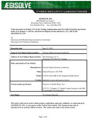
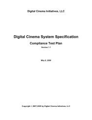
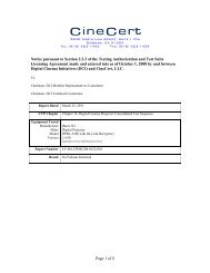
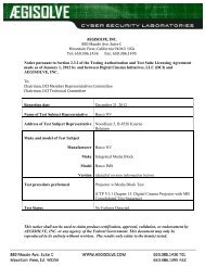
2.1. Functional Framework2. SYSTEM OVERVIEWFor the purpose of documenting the specific requirements and specifications for a <strong>Digital</strong><strong>Cinema</strong> system, it is helpful to divide the system into a set of components 2 , which are:• <strong>Digital</strong> <strong>Cinema</strong> Distribution Master (DCDM) – Contains system requirements regardingthe uncompressed, unencrypted file or set of files containing the content and itsassociated data.• Compression – Contains system requirements regarding the process that reducesredundancy in source essence data and its inverse, decompression,• Packaging – Contains system requirements for the process of encryption and decryptionof compressed image and audio essence, wrapping and unwrapping of compressed andencrypted files for distribution and playback.• Transport – Contains requirements related to the distribution of the packaged media.• Theater System – Contains system requirements for the equipment installed at a theaterfor control, scheduling, logging and diagnostics.• Projection – Contains system requirements regarding the performance characteristicsused to display the image on the screen.• Security – Contains system requirements that bear on the protection of contentintellectual property rights. Processes for key management, link encryption, ForensicMarking and logging are constituent elements of the security design.A functional framework of a <strong>Digital</strong> <strong>Cinema</strong> encoding and a decoding system are shown belowin Figure 1 and Figure 2.2 The specifications and performance requirements for each of these components will be described in the subsequentsections<strong>DCI</strong> <strong>Digital</strong> <strong>Cinema</strong> System Specification v.1.2 Page 19
<strong>DCI</strong> <strong>Digital</strong> <strong>Cinema</strong> System Specification v.1.2 Page 20Figure 1: System Overview Functional Encode Flow
<strong>DCI</strong> <strong>Digital</strong> <strong>Cinema</strong> System Specification v.1.2 Page 21Figure 2: System Overview Functional Decode Flow
2.1.1. Major System Concepts2.1.1.1. <strong>Digital</strong> Source Master (DSM)The <strong>Digital</strong> Source Master (DSM) is created in post-production and can be used toconvert into a <strong>Digital</strong> <strong>Cinema</strong> Distribution Master (DCDM). The DSM can also be used toconvert to a film duplication master, a home video master, and/or a master for archivalpurposes. It is not the intention of this document to, in any way, specify the DSM. This isleft to the discretion of the content provider. The content could come from a wide rangeof sources with a wide range of technical levels.2.1.1.2. CompositionWhen discussing <strong>Digital</strong> <strong>Cinema</strong> content, it was realized that other content besidesfeature films would make use of the same digital system. Therefore, a new term wascreated to refer to any content that would have similar requirements to feature filmcontent. The term “Composition” refers to all of the essence and metadata required for asingle presentation of a feature, or a trailer, or an advertisement, or a logo to create apresentation using a digital system. This term will be used throughout this document andis intended to refer to a single element such as one and only one feature, trailer,advertisement or logo.2.1.1.3. <strong>Digital</strong> <strong>Cinema</strong> Distribution Master (DCDM)This document specifies a DCDM for the purpose of exchanging the image, audio andsubtitles to encoding systems and to the <strong>Digital</strong> <strong>Cinema</strong> playback system. The DCDM isthe output of the <strong>Digital</strong> <strong>Cinema</strong> post-production process (not to be confused with thefeature post-production process, which creates the DSM) and is the image structure,audio structure, subtitle structure. These structures are mapped into data file formatsthat make up the DCDM. This master set of files can then be given a quality controlcheck to verify items like synchronization and that the composition is complete. Thisrequires the DCDM files to be played back directly to the final devices (e.g., projectorand sound system) in their native decrypted, uncompressed, unpackaged form.2.1.1.4. <strong>Digital</strong> <strong>Cinema</strong> Package (DCP)Once the DCDM is compressed, encrypted and packaged for distribution, it isconsidered to be the <strong>Digital</strong> <strong>Cinema</strong> Package or DCP. This term is used to distinguishthe package from the raw collection of files known as the DCDM. Shown below is atypical flow for <strong>Digital</strong> <strong>Cinema</strong>. When the DCP arrives at the theater, it is eventuallyunpackaged, decrypted and decompressed to create the DCDM*, where DCDM* imageis visually indistinguishable from the original DCDM image.DSM → DCDM → DCP → DCDM* → Image and SoundNote: Integrated projector and Media Blocks are strongly recommended. However in theexclusive case to accommodate a 2K, 48 FPS, 12 bit DCDM to use [SMPTE 372M DualLink HD-SDI] as an interface, it is acceptable, but not recommended, to allow 10 bit colorsub-sampling to create the DCDM* at the output of the Image Media Block decoder. Thisbit depth reduction and color subsampling is only allowed in the single combination of aDCDM at 2K, 48 FPS being transported over a link encrypted SMPTE 372M connection.<strong>DCI</strong> <strong>Digital</strong> <strong>Cinema</strong> System Specification v.1.2 Page 22
2.1.1.5. Hierarchical Image StructureThe DCDM shall use a hierarchical image structure that supports both 2K and 4Kresolution files (See Section Section 3.2.1 Image Concepts and Requirementsso thatstudios can choose to deliver either 2K or 4K masters and both 2K and 4K projectorscan be deployed and supported. The supported mastering and projecting combinationsare illustrated in Figure 3: Hierarchical Image StructureMedia Blocks (MB) for 2K projectors are required to be able to extract and display the2K-resolution component from the 2K/4K DCP file(s). Media Blocks for 4K projectors arerequired to be able to output and display the full 4K DCDM. In the case of a 2K DCDM,the output of the Media Block is a 2K image. It is the responsibility of the 4K projectors toup-sample the image.Figure 3: Hierarchical Image Structure2.1.1.6. File / Frame-Based SystemThis <strong>Digital</strong> <strong>Cinema</strong> system is built upon a data file-based design, i.e., all of the contentis made up of data stored in files. These files are organized around the image frames.The file is the most basic component of the system.2.1.1.7. Store and ForwardThis <strong>Digital</strong> <strong>Cinema</strong> system uses a store-and-forward method for distribution. This allowsthe files to be managed, processed and transported in non-real time. Non-real time couldbe interpreted as slower than real time, or faster than real time. After being transportedto the theater, the files are stored on a file server until playback. However, duringplayback and projection, the <strong>Digital</strong> <strong>Cinema</strong> content plays out in real time.<strong>DCI</strong> <strong>Digital</strong> <strong>Cinema</strong> System Specification v.1.2 Page 23
2.1.1.8. ReelsFeature films have been sub-divided for some time into discreet temporal units for filmsystems called reels. This concept and practice will continue in use for the <strong>Digital</strong><strong>Cinema</strong> system. In <strong>Digital</strong> <strong>Cinema</strong>, a reel represents a conceptual period of time havinga specific duration chosen by the content provider. <strong>Digital</strong> <strong>Cinema</strong> reels can then beelectronically spliced together to create a feature presentation.2.1.1.9. Component DesignFor the purpose of interoperability, the hardware and software used in the <strong>Digital</strong><strong>Cinema</strong> system shall be easily upgraded as advances in technology are made.Upgrades to the format shall be designed in a way so that content can be distributed andplayed on the latest hardware and software, as well as earlier <strong>DCI</strong>-compliant equipmentinstallations.The <strong>Digital</strong> <strong>Cinema</strong> system shall provide a reasonable path for upgrading to futuretechnologies. It shall be based upon a component architecture (e.g., Mastering,Compression, Encryption, Transport, Storage, Playback, Projection), that allows for thecomponents to be replaced or upgraded in the future without the replacement of thecomplete system. It is the intention of this <strong>Digital</strong> <strong>Cinema</strong> specification to allow foradvances in technology and the economics of technology advancement.2.1.1.10. Storage and Media BlockStorage and Media Block are components of the theater playback system. Storage is thefile server that holds the packaged content for eventual playback. The Media Block is thehardware device (or devices) that converts the packaged content into the streaming datathat ultimately turns into the pictures and sound in the theater. These two componentscan be physically contained together or they can be physically separate from each other.Media Blocks are secure entities and the specific nature of that security is defined inSection 9: SECURITY.<strong>DCI</strong> <strong>Digital</strong> <strong>Cinema</strong> System Specification v.1.2 Page 24
3. DIGITAL CINEMA DISTRIBUTION MASTER3.1. Overview3.1.1. IntroductionThe <strong>Digital</strong> <strong>Cinema</strong> Distribution Master, or DCDM, is a collection of data file formats, whosefunction is to provide an interchange standard for <strong>Digital</strong> <strong>Cinema</strong> presentations. It is arepresentation of images, audio and other information, whose goal is to provide a completeand standardized way to communicate movies (compositions) between studio, postproductionand exhibition. A specific instance of a DCDM is derived from a <strong>Digital</strong> SourceMaster (DSM) that is created as a result of a post-production assembly of the elements of amovie (composition). A DCDM can be transformed into a <strong>Digital</strong> <strong>Cinema</strong> Package fordistribution to exhibition sites (see Section 5: PACKAGING). Alternatively, it can be sentdirectly to a playback system for quality control tasks.3.1.2. DCDM System OverviewFor the purpose of documenting the specific requirements and specifications for the DCDM,it is helpful to divide the system into a set of components. The specifications andrequirements for each of these components will be described in the following sections:• Image – The image specification and file format• Audio – The audio specification and file format• Subtitleso Subpicture – The pre-rendered open text specification and file formato Timed Text – The Timed Text data specification and file format3.1.3. Major DCDM ConceptsThe <strong>Digital</strong> <strong>Cinema</strong> Distribution Master (DCDM) is the fundamental interchange element inthe system. Since digital mastering technology will continue to change and develop withtime, the DCDM is designed to accommodate growth. There are several areas that will beaffected by the progression of the mastering technology, such as color space, resolution,sampling frequencies, quantizing bit depths and interfaces.In the process of creating feature films, a <strong>Digital</strong> Source Master, or DSM, is produced. TheDSM creates many elements (e.g., Film Distribution Masters, DCDM, Home Video Mastersand Broadcast Masters). It is not the goal of this specification to define the DSM. Instead, itis recognized that the DSM can be made of any color space, resolution, sampling frequency,color component bit depths and many other metrics.If the content does not meet this DCDM specification, it is the content provider’sresponsibility to convert the DSM into the DCDM specification, defined in this section, beforeit can be used in the <strong>Digital</strong> <strong>Cinema</strong> system.A set of DCDM files (image, audio, subtitles, etc.) contains all of the content required toprovide a <strong>Digital</strong> <strong>Cinema</strong> presentation. The DCDM provides two functions, an interchangefile format, and a playback format that is directly sent from the Media Block to the projector(this is referred to as DCDM*). For use in interchange, the encoding process can beperformed in real time or non-real time. For use in playback, the DCDM* is logically requiredto playback in real time.<strong>DCI</strong> <strong>Digital</strong> <strong>Cinema</strong> System Specification v.1.2 Page 25
Metadata within the DCDM provides a method to synchronize image, audio and subtitles.This method is used to synchronize the tracks in order to maintain frame-based lip sync fromthe beginning to the end of a presentation. This is different from the requirement tosynchronize the system clocks of different pieces of equipment to run at consistentfrequencies. The first part addresses the packaging of the picture, sound and subtitles insuch a way as to establish and maintain a timing relationship between these tracks ofessence. The second part addresses the inter-operability of equipment in a theater systemand is therefore discussed in Section 7 THEATER SYSTEMS.3.1.4. DCDM Fundamental Requirements3.1.4.1. Common File FormatsThe DCDM is required to use a common standardized file format for each element(image, audio, subtitles, etc.). The DCDM image file format is required to be an MXFconformantfile, based on existing SMPTE standards. The DCDM audio file format isrequired to be based on Broadcast Wave.3.1.4.2. Frame RatesThe DCDM image structure is required to support a frame rate of 24.000 Hz. The DCDMimage structure can also support a frame rate of 48.000 Hz for 2K image content only.The frame rate of any individual DCDM master is required to remain constant. Metadatais carried in the image data file format to indicate the frame rate.3.1.4.3. SynchronizationFiles within the DCDM set are required to carry information to provide for frame-basedsynchronization between each file. At a minimum, they are required to include a “start offile” and a continuous frame count.3.2. Image Specification3.2.1. Image Concepts and Requirements3.2.1.1. IntroductionThis section defines a common interchange for <strong>Digital</strong> <strong>Cinema</strong> uncompressed imagestructures and files. This includes an image structure, aspect ratios, common colorspace, bit depth, transfer function, and the file format required to present contentproperly to a <strong>Digital</strong> <strong>Cinema</strong> projector.3.2.1.2. Image StructureThe DCDM shall provide an image structure that shall use equally sampled tristimuluscode values to represent each pixel. The maximum number of horizontal and verticalpixels shall be constrained to fit within one of the following image pixel arrays: Thenumber of active pixels (e.g., the pixels of the image structure that are intended to bedisplayed) shall extend to the maximum in either the horizontal or vertical direction of thedefined level of operation as shown in Table 1. For example, a 4K image file with a2.39:1 aspect ratio would require an image pixel array of 4096x1716, therefore filling thehorizontal resolution of the 4K container. The pixel orientation, as displayed on thescreen, shall be understood to flow from left to right and top to bottom. Also, the<strong>DCI</strong> <strong>Digital</strong> <strong>Cinema</strong> System Specification v.1.2 Page 26
horizontal and vertical pixel count shall begin with 0. For example, the top left pixel of thedisplayed image shall be denoted as (0, 0).LevelHorizontalPixelsVerticalPixelsPixelAspectRatioFrameRate1 4096 2160 1:1 24.002 2048 1080 1:1 48.003 2048 1080 1:1 24.00Table 1: Image Structure3.2.1.3. Center of ImageThe center of the image structure shall correspond to the center of its image active pixelarray. Horizontally, there will be an equal number of pixels to the left and to the right ofthe center point. Vertically, there will be an equal number of pixels above and below thecenter point. The center of the image structure will depend on the down stream mappingof the content (e.g., HDSDI or TIFF files). For 4K (4096x1716) image structure mappedto a TIFF file, the center is between horizontal pixels 2047 and 2048 (note: pixel countsbegin at (0,0)) and between vertical pixels 857 and 858. For 2K (2048x858) imagestructure mapped into an HDSDI stream, the center is between horizontal pixels 1023and 1024 and between vertical pixels 539 and 540.3.2.1.4. ColorimetryThe color encoding of the <strong>Digital</strong> <strong>Cinema</strong> Distribution Master (DCDM) embodies adevice-independent, X’Y’Z’ color space. Since the DCDM incorporates all of the creativecolor decisions and these decisions will be made on a calibrated projector in a controlledmastering room, it is by definition an output-referred image state as described in [CIEPublication 15:2004, Colorimetry, 3 rd Edition]. The picture is colorimetrically defined forits intended display on the cinema screen.3.2.1.5. Encoding PrimariesThe DCDM shall use the 1931 CIE system of colorimetry [CIE Publication 15:2004,Colorimetry, 3rd Edition] (x, y coordinates) to describe the color primaries X, Y, and Z asa gamut container (see Table 2).EncodingPrimariesx y u’ v’X 1.0000 0.0000 4.0000 0.0000Y 0.0000 1.0000 0.0000 0.6000Z 0.0000 0.0000 0.0000 0.0000Table 2: Chromaticity Coordinates 3 of the Encoding Primaries3 x, y, u’, v’ refers to the chromaticity coordinates defined by the CIE<strong>DCI</strong> <strong>Digital</strong> <strong>Cinema</strong> System Specification v.1.2 Page 27
3.2.1.6. Transfer FunctionThe CIE XYZ tristimulus values must be calculated with a normalizing constant that setsthe Y tristimulus value equal to the absolute luminance 4 in cd/m 2 . With this specificationof the color, the following equations define the encoding transfer function. 53.2.1.7. Bit DepthThe bit depth for each code value for a color component shall be 12 bits. This yields 36bits per pixel.3.2.1.8. Aspect RatioSome examples for the accommodation of images of various aspect ratios in thecontainers are shown in Table 3.Where:Ph = number of active horizontal pixels in imagePv = number of active vertical pixels in imageAR = the aspect ratio of the image (ratio of width to height, expressedas a decimal)Level Ph Pv AR PixelAspectRatio1 4096 1716 239 1:11 3996 2160 1.85 1:12 2048 858 2.39 1:12 1998 1080 1.85 1:1Table 3: Example Image Aspect Ratios4 The peak luminance as shown in the transfer function equation is 52.37 cd/m 2 . The extra headroom is reserved toaccommodate a range of white points including D 55 , D 61 and D 65 , while still supporting the reference white luminance of48 cd/m 2 as specified in SMPTE 196E for <strong>Digital</strong> <strong>Cinema</strong>-Screen Luminance Level, Chromaticity and Uniformity.5 The INT operator returns the value of 0 for fractional parts in the range of 0 to 0.4999… and +1 for fractional parts in therange 0.5 to 0.9999…, i.e., it rounds up fractions above 0.5.<strong>DCI</strong> <strong>Digital</strong> <strong>Cinema</strong> System Specification v.1.2 Page 28
3.2.2. DCDM Image File Format3.2.2.1. IntroductionThe DCDM image file format is mapped into TIFF.3.2.2.2. File MappingThe DCDM Image Structure shall be mapped into the TIFF Rev 6.0 File Format andfurther constrained as follows:• 16 bits each per X', Y', and Z' channel, stored in the nominal TIFF R, G and Bchannels.• The DCDM gamma-encoded X', Y' and Z' color channels are represented by12-bit unsigned integer code values. These 12 bits are placed into the mostsignificant bits of 16-bit words, with the remaining 4 bits filled with zeroes.• The image orientation shall place the first pixel in the upper left corner of theimage.• The DCDM picture file shall contain only the active pixels in the image. Inother words, it is not allowed to pad the picture to the full size of the DCDMcontainer.3.2.2.3. SynchronizationThe DCDM file format is required to contain metadata that allows for synchronization ofthe images with other content:• Each directory shall contain only one contiguous sequence of frames.• For assembled reels, a separate directory shall be used for each reel with thefollowing naming convention:oCompositionName.Reel_#• For inserts, the directory naming convention shall be:oFeatureName.Reel_#.Insert_#• Each reel shall contain sequentially numbered frames, using the following filenaming convention. All names when sorted alphabetically shall be insequential order (leading zeroes required). Therefore, the only thing thatchanges in the sequence is the frame numbers.ooCompositionName.Reel_#.FrameNumber.tifExample: Stealth.Reel_1.00001.tif3.2.2.4. Image Metadata Required FieldsImage information and parameters, required to successfully interchange the DCDMImage Structure, shall be provided to the mechanism that will ingest the DCDM.Each frame in the reel shall contain accurate and complete metadata, but it ispermissible to read and extract the reel-based metadata from the first frame of a reel touse as a metadata “slate” for the rest of the frames in the reel.<strong>DCI</strong> <strong>Digital</strong> <strong>Cinema</strong> System Specification v.1.2 Page 29
The information, as shown in Table 4 below, is the minimum required information tosuccessfully interchange files.Data Element NameData Element DefinitionActive Horizontal Pixels (Ph) Total number of active horizontal pixels in the image containerActive Vertical Pixels (Pv) Total number of active vertical pixels in the image containerFrame RateThe rate that images are to be projected, expressed in frames per secondFrame CountThe integer number of frames in a sequenceTable 4: Required Image Structure Information3.3. Audio Specification3.3.1. Audio Concepts and Requirements<strong>Digital</strong> <strong>Cinema</strong> audio requires standardized characteristics, channel mapping and a fileformat to successfully playback in a motion picture theater.3.3.2. Audio Characteristics3.3.2.1. IntroductionThe necessary characteristics for standardized audio are: bit depth, sample rate,reference level and channel count. These parameters are given below.3.3.2.2. Bit DepthThe bit depth shall be 24 bits per sample. DSM Audio Material having other bit depthsshall be justified to the most significant bit per [AES3-2003 Section 4.1.1].3.3.2.3. Sample RateIrrespective of the associated image frame rate, the audio sample rate shall be eitherforty-eight or ninety-six thousand samples per second per channel, commonly expressedas 48.000 or 96.000 kHz. At 24 FPS playback, there are exactly 2,000 audio samplesper frame for 48.000 kHz and exactly 4,000 audio samples per frame for 96.000 kHz. At48 FPS playback, there are exactly 1,000 audio samples per frame for 48.000 kHz andexactly 2,000 audio samples per frame for 96.000 kHz.A theater playback system shall have the capability of performing sample rateconversion as needed.3.3.2.4. Channel CountThe delivered digital audio, contained within the <strong>Digital</strong> <strong>Cinema</strong> Package (DCP), shallsupport a channel count of sixteen full-bandwidth channels.3.3.2.5. <strong>Digital</strong> Reference Level<strong>Digital</strong> inputs and outputs shall have a nominal reference level of -20 dBFS (decibelbelow full scale) and output 85 dBc (decibels referenced to the carrier) sound pressurelevel per channel measured with pink noise.<strong>DCI</strong> <strong>Digital</strong> <strong>Cinema</strong> System Specification v.1.2 Page 30
3.3.3. Channel MappingChannel mapping defines where the individual audio channels are assigned and the labelingof channels in a <strong>Digital</strong> <strong>Cinema</strong> audio system. This is done to aid in the identification and thelocation of channels, thus, enabling uniform expression and communication of source audiochannels to <strong>Digital</strong> <strong>Cinema</strong> playback loudspeakers. The general parameters for 8 and 6channel mapping are given in Table 5 and Table 6 for reference. Suggested speakerplacement for a <strong>Digital</strong> <strong>Cinema</strong> auditorium is shown in Figure 4.AES Pair#/Ch# Channel # Label / Name Description1/1 1 L/Left Far left screen loudspeaker1/2 2 R/Right Far right screen loudspeaker2/1 3 C/Center Center screen loudspeaker2/2 4 LFE/Screen Screen Low Frequency Effects subwoofer loudspeakers3/1 5 Ls/Left Surround Left wall surround loudspeakers3/2 6 Rs/Right Surround Right wall surround loudspeakers4/1 7 Lc/Left Center Mid left to center screen loudspeaker4/2 8 Rc/Right Center Mid right to center screen loudspeaker5/1 9 Unused5/2 10 Unused/User Defined6/1 11 Unused/User Defined6/2 12 Unused/User Defined7/1 13 Unused/User Defined7/2 14 Unused/User Defined8/1 15 Unused/User Defined8/2 16 Unused/User DefinedTable 5: Eight Channel Mapping<strong>DCI</strong> <strong>Digital</strong> <strong>Cinema</strong> System Specification v.1.2 Page 31
AES Pair#/Ch# Channel # Label / Name Description1/1 1 L/Left Far left screen loudspeaker1/2 2 R/Right Far right screen loudspeaker2/1 3 C/Center Center screen loudspeaker2/2 4 LFE/Screen Screen Low Frequency Effects subwooferl d k3/1 5 Ls/Left Surround Left wall surround loudspeakers3/2 6 Rs/Right Surround Right wall surround loudspeakers4/1 7 Unused4/2 8 Unused5/1 9 Unused5/2 10 Unused/User Defined6/1 11 Unused/User Defined6/2 12 Unused/User Defined7/1 13 Unused/User Defined7/2 14 Unused/User Defined8/1 15 Unused/User Defined8/2 16 Unused/User DefinedTable 6: Six Channel Mapping<strong>DCI</strong> <strong>Digital</strong> <strong>Cinema</strong> System Specification v.1.2 Page 32
Figure 4: Suggested Auditorium Speaker Placement<strong>DCI</strong> <strong>Digital</strong> <strong>Cinema</strong> System Specification v.1.2 Page 33
3.3.4. File Format3.3.4.1. GeneralThe audio file format shall comply with the Broadcast Wave file format (.wav), per [ITUTech 3285 version 1 (PCM WAVE coding)], is extended and constrained as furtherdescribed here.The audio file shall remain uncompressed throughout the <strong>Digital</strong> <strong>Cinema</strong> system. Thisshall include packaging, distribution and storage.3.3.4.2. SynchronizationThe Broadcast Wave (.wav) file is required to contain metadata that indicates the firstsample of audio data. The metadata is also required to contain a continuous frame countrelative to the image as well as the sample rate.3.4. Text Rendering3.4.1. Text Rendering Concepts and Requirements<strong>Digital</strong> <strong>Cinema</strong> has a subtitling system that can convey multiple languages. Along withsubtitling, there are text localizations, titling and captioning that may also be a part of thenew <strong>Digital</strong> <strong>Cinema</strong> experience. However, captioning and subtitling are identified as twoseparate systems having different roles in the presentation of content and may havedifferent methods of rendering.Traditionally, the audience for captioning is the deaf and hard of hearing (D/HOH). Thedelivery can be done in different ways. These include closed systems that are optional-tothe-viewerdelivery and are usually displayed on a personal device (such as a wirelessreceiver), or delivery to an obscured device that is viewable with an appliance (such as arear-wall display viewed through a mirror).Subtitling is generally associated with a foreign language translation for localizing a movie ina particular geographic territory. Subtitles are typically open or displayed on the screen aspart of the movie, without option. Subtitling and localizations are generally designed for aparticular look with creatively chosen fonts and drop shadows.With captioning, the source language (what is spoken in the movie) and the target language(what appears as captions) are most often, as in the case of English, the same. Forsubtitling, the source language and target language are different because the goal ofsubtitling is to translate the movie.Subtitles and captions, if supplied, may be one or more of the following:• Pre-composited into the <strong>Digital</strong> <strong>Cinema</strong> image files (burned-in)• Pre-rendered PNG bitmaps (subpicture), or• Documents containing text and attributes for:o Rendering in a specified font (Timed Text) and overlaid by the server, an inlineprocessor or the <strong>Digital</strong> <strong>Cinema</strong> projectorooLED displays driven by a captioning processor receiving data from the <strong>Digital</strong><strong>Cinema</strong> server, orSeparate projection systems driven by a captioning processor receiving data<strong>DCI</strong> <strong>Digital</strong> <strong>Cinema</strong> System Specification v.1.2 Page 34
from the <strong>Digital</strong> <strong>Cinema</strong> serverSection 3.4.2 Subpicture defines the subpicture specifications, while Section 3.4.3 TimedText Concepts and Requirements defines the specification for Timed Text streams, whichcan be used for either subtitles or captions or both. Burned-in subtitles are not addressedsince they are something that would occur in the mastering of the content and would beinherent in the image.3.4.2. Subpicture3.4.2.1. IntroductionA subpicture data stream is a multiple-image data stream intended for the transport ofvisual data supplemental to a motion picture. The data is designed for graphic overlaywith the main image of a <strong>Digital</strong> <strong>Cinema</strong> motion picture. It is designed only for an opendisplay and not for a closed display. It is envisioned that the subpicture data stream,when employed, will typically be used for the transport of subtitle data.3.4.2.2. File FormatSubpicture data is required to be encoded as a standardized, XML-based document.Such a standard is required to define both Timed Text and subpicture encoding methodsallowing mixed-media rendering. Subpicture frames are required to be encoded as[ISO/IEC 15948:2004] PNG files.3.4.2.3. Rendering IntentThe PNG file is required to be rendered with knowledge of color space and pixel matrixof the DCDM. The PNG file is required to be mastered at the same resolution as theDCDM.For example, a DCP containing a 4K master will require 4K PNG files and no otherresolution PNG files. When played on a 2K projector, it is the responsibility of the 2Kprojector to downsample the 4K PNG files such that they display with the correct sizewith respect to the image data. And, a DCP containing a 2K master will require 2K PNGfiles and no other resolution PNG files. When played on a 4K projector, it is theresponsibility of the 4K projector to upsample the 2K PNG files appropriately.3.4.2.4. Frame Rate and TimingThe XML navigation file specifies the temporal resolution of the subpicture file. A Framecount, Time In, Time Out, Fade Up Time and Fade Down Time, which correspond to theimage, shall be included. The subpicture frame rate shall be equal to the frame rate ofthe associated DCDM image file.3.4.2.5. SynchronizationThe equipment or system that encodes or decodes the subpicture file is required toensure that temporal transitions within the subpicture file are correctly synchronized withother associated DCDM files. The <strong>Digital</strong> <strong>Cinema</strong> equipment and subpicture file isrequired to re-synchronize after a restart of the system.<strong>DCI</strong> <strong>Digital</strong> <strong>Cinema</strong> System Specification v.1.2 Page 35
3.4.3. Timed Text Concepts and Requirements3.4.3.1. IntroductionTimed Text (e.g., captions and/or subtitles) is text information that may be presented atdefinite times during a <strong>Digital</strong> <strong>Cinema</strong> presentation.3.4.3.2. File FormatTimed Text data is required to be encoded as a standardized, XML-based document.Note: This provides for presentation via:• Overlay in main or secondary projector image (open), or• External display (closed)3.4.3.3. RestartThe <strong>Digital</strong> <strong>Cinema</strong> equipment and Timed Text file is required to re-synchronize after arestart of the system.3.4.3.4. Default FontFont files are required to be used to render Timed Text for subtitle applications. Fontfiles can be used to render Timed Text for caption applications. When used, font files arerequired to conform to [ISO/IEC 00000 OpenType 6 ]. Timed Text files are required to beaccompanied by all font files required for reproduction of the Timed Text.The Timed Text file format is required to support a default character set. It is requiredthat there be a default Unicode character set and a default font for that character set.In event that an external font file is missing or damaged, the subtitle rendering device isrequired to use a default font supplied by the manufacturer. The default character set isrequired to be a Unicode ISO Latin-1 character set. The default font is required toconform to [ISO/IEC 00000 OpenType] and support the ISO Latin-1 character set.3.4.3.5. IdentificationThe Timed Text format requires the cardinal language of the text to be identified.3.4.3.6. SearchabilityA pure text stream is encouraged to isolate content from rendering markup forsearchability.3.4.3.7. Multiple CaptionsThe Timed Text format shall allow the display of multiple captions simultaneously. Thereshall be a maximum number of 3 lines of text allowed for simultaneous display.Note: This allows for spatial representation for captions when two people are talkingsimultaneously.6 OpenType specification is a work-in-progress. Number will be added when completed.<strong>DCI</strong> <strong>Digital</strong> <strong>Cinema</strong> System Specification v.1.2 Page 36
3.4.3.8. SynchronizationThe equipment or system that encodes or decodes the Timed Text file is required toensure that temporal transitions within the data stream are correctly synchronized withother associated DCDM data streams.3.4.4. Show Control Concepts and RequirementsCurrent day control systems, usually called automation systems, orchestrate theater subsystemssuch as curtains, masking and lights. <strong>Digital</strong> <strong>Cinema</strong> control methods are expectedto differ significantly from those found in theaters today. Supervisory types of control will bemuch broader in application than in today’s systems, allowing interface to specializedcontrols for theatrical events.Many of these concepts and requirements are covered in Section 5 PACKAGING andSection:7 THEATER SYSTEMS. Some of the fundamental information pertaining toencoding is covered here, with the detailed information for its use covered in Section 7THEATER SYSTEMS3.4.5. Show Controls3.4.5.1. IntroductionMany of today’s automation controls are driven by a time-based event list such as thesystem's Show Playlist, and can be classified by their show control functions, as in thepartial list below.• First frame of content• First frame of intermission• First frame of end credits• First frame of end credits on black• Last frame of contentShow control events or cues are required for the theater system operator to pre-programthe timing of show control events. Such events or cues may indicate events such as thebeginning of the title, beginning of the intermission, beginning of the credits, and the endof the feature. The events or cues will normally be placed into the <strong>Digital</strong> <strong>Cinema</strong>Composition Playlist, as defined in Section:5 PACKAGING<strong>DCI</strong> <strong>Digital</strong> <strong>Cinema</strong> System Specification v.1.2 Page 37
THIS PAGE LEFT BLANK INTENTIONALLY<strong>DCI</strong> <strong>Digital</strong> <strong>Cinema</strong> System Specification v.1.2 Page 38
4.1. Introduction4. COMPRESSIONImage Compression for <strong>Digital</strong> <strong>Cinema</strong> uses data reduction techniques to decrease the size ofthe data for economical delivery and storage. The system uses perceptual coding techniques toachieve an image compression that is visually lossless. It is important to note that imagecompression is typically used to ensure meeting transmission bandwidth or media storagelimitations. This results in image quality being dependent on scene content and delivered bitrate. <strong>Digital</strong> <strong>Cinema</strong> image compression is much less dependent upon bandwidth or storagerequirements, thereby making bit rate dependent on desired image quality rather than thereverse.4.2. Compression StandardThe compression standard shall be JPEG 2000 (see [ISO/IEC 15444-1]).4.3. Decoder Specification4.3.1. Definitions• A 2K distribution – the resolution of the DCDM* 7 container is 2048x1080.• A 4K distribution – the resolution of the DCDM* 7 container is 4096x2160.• A 2K decoder outputs up to 2048x1080 resolution data.• A 4K decoder outputs up to 4096x2160 resolution data from a 4K compressed fileand outputs up to 2048x1080 resolution data from a 2K compressed file.• All decoders shall decode both 2K and 4K distributions. It is the responsibility of the4K projector to upres the 2K file. In the case of a 2K decoder and a 4K distribution,the 2K decoder need read only that data necessary to decode a 2K output from the4K distribution. The decoder (be it a 2K decoder or a 4K decoder) need not upsamplea 2K image to a 4K projector or down-sample a 4K image to a 2K projector.4.3.2. Decoder Requirements• Once deployed, the decoder, for any given projector, shall not be required to beupgraded.• The output of the decoder shall conform to Section 3.2 Image Specification. Theseimages are basically:o 4K = 4096x2160 at 24 FPSo 2K = 2048x1080 at 24 or 48 FPSo Color: 12 bit, X’Y’Z’• Enhanced parameter choices shall not be allowed in future distribution masters, ifthey break decodability in a deployed compliant decoder.7 The DCP arrives at the theater, it is unpackaged, decrypted and decompressed to create the DCDM*, where DCDM* isvisually indistinguishable from the original DCDM (where the original DCDM is the input to the <strong>Digital</strong> <strong>Cinema</strong>Mastering Process<strong>DCI</strong> <strong>Digital</strong> <strong>Cinema</strong> System Specification v.1.2 Page 39
• All decoders shall decode each color component at 12 bits per sample with equalcolor/component bandwidth. Decoders shall not subsample chroma.• A 4K decoder shall decode all data for every frame in a 4K distribution. A decodershall not discard data (including resolution levels or quality layers) to keep up withpeak decoding rates.• A 2K decoder shall decode 2K data for every frame in a 4K distribution and it shalldecode a 2K distribution. It may discard only the highest resolution level of a 4Kdistribution. It shall not discard other data such as further resolution levels or qualitylayers.• All decoders shall implement the 9/7 inverse wavelet transform with at least 16 bitfixed point precision.• All decoders shall implement the inverse Irreversible Color Transform (ICT) using atleast 16 bit fixed point precision.4.4. Codestream SpecificationAll codestreams shall fully conform with [ISO 15444-1:2004/PDAM 1 (soon to be Amendment1)], as more fully constrained as follows:• The capability parameter for a 2K distribution shall be Rsiz = 3, for a 4K distribution itshall be Rsiz = 4.• All image frames shall be untiled. More precisely, the entire image shall be encoded as asingle tile.• The image and tile origins shall both be at (0, 0).• There shall be no more than 5 wavelet transform levels for 2K content and no more than6 wavelet transform levels for 4K content. There shall be no less than one wavelettransform level for 4K content. Additionally, every color component of every frame of adistribution shall have the same number of wavelet transform levels.• Codeblocks shall be of size 32x32.• The codeblock coding style shall be SPcod, SPcoc = 0b00000000.• All precinct sizes at all resolutions shall be 256x256, except the lowest frequencysubband, which shall have a precinct size of 128x128.• There shall be no region of interest, i.e., Region of interest (RGN) marker segments aredisallowed.• Coding style Default (COD), Coding style Component (COC), Quantization Default(QCD), and Quantization Component (QCC) marker segments shall appear only in themain header.• Packed Packet headers, Main header (PPM) and Packed Packet headers, Tile-partheader (PPT) marker segments are forbidden.• The progression order for a 2K distribution shall be Component-Position-Resolution-Layer (CPRL). Progression Order Change (POC) marker segments are forbidden in 2Kdistributions.• For a 4K distribution, there shall be exactly one POC marker segment in the mainheader. Other POC marker segments are forbidden. The POC marker segment shallspecify exactly two progressions having the following parameters:<strong>DCI</strong> <strong>Digital</strong> <strong>Cinema</strong> System Specification v.1.2 Page 40
oooFirst progression:RSpoc = 0, CSpoc = 0, LYEpoc = L, REpoc = D, CEpoc = 3, Ppoc = 4Second progression:RSpoc = D, CSpoc = 0, LYEpoc = L, REpoc = D+1, CEpoc = 3, Ppoc = 4In the above, D is the number of wavelet transform levels and L is the number ofquality layers. The constant 3 specifies the number of color components, and theconstant 4 specifies CPRL progression.Note: This POC marker segment ensures that all 2K data precede all 4K data. Withineach portion (2K, 4K), all data for color component 0 precede all data for colorcomponent 1, which in turn precede all data for color component 2.• Each compressed frame of a 2K distribution shall have exactly 3 tile parts. Each tile partshall contain all data from one color component.• Each compressed frame of a 4K distribution shall have exactly 6 tile parts. Each of thefirst 3 tile parts shall contain all data necessary to decompress one 2K color component.Each of the next 3 tile parts shall contain all additional data necessary to decompressone 4K color component. The resulting compliant codestream structure is diagramed inTable 7. Assuming D wavelet transform levels (D+1 resolutions), the box labeled2K_i (i = 0, 1, 2) contains all JPEG 2000 packets for color component i, resolutions 0through D-1. The box labeled 4K_i (i = 0, 1, 2) contains all JPEG 2000 packets for colorcomponent i, resolution D.MainHeaderTile-partHeader2K_0Tile-partHeader2K_1Tile-partHeader2K_2Tile-partHeader4K_0Tile-partHeader4K_1Tile-partHeader4K_2Table 7: Codestream Structure• Tile-part Lengths, Main header (TLM) marker segments shall be required in all frames ofall distributions.Note: This facilitates extraction of color components and resolutions (2K vs. 4K).• Distribution masters shall have exactly one quality layer.• For a frame rate of 24 FPS, a 2K distribution shall have a maximum of 1,302,083 bytesper frame (aggregate of all three color components including headers). Additionally, itshall have a maximum of 1,041,666 bytes per color component per frame including allrelevant tile-part headers.• For a frame rate of 48 FPS, a 2K distribution shall have a maximum of 651,041 bytes perframe (aggregate of all three color components including headers). Additionally, it shallhave a maximum of 520,833 bytes per color component per frame including all relevanttile-part headers.• A 4K distribution shall have a maximum of 1,302,083 bytes per frame (aggregate of allthree color components including headers). Additionally, the 2K portion of each frameshall satisfy the 24 FPS 2K distribution requirements as stated above.Note: For information purposes only, this yields a maximum of 250 Mbits/sec total and amaximum of 200 Mbits/sec for the 2K portion of each color component<strong>DCI</strong> <strong>Digital</strong> <strong>Cinema</strong> System Specification v.1.2 Page 41
THIS PAGE LEFT BLANK INTENTIONALLY<strong>DCI</strong> <strong>Digital</strong> <strong>Cinema</strong> System Specification v.1.2 Page 42
5.1. Introduction5. PACKAGINGThe DCDM, as stated in the System Overview, is a collection of files, such as picture essencefiles and audio essence files. These files, as they stand by themselves, do not represent acomplete presentation. Synchronization tools, asset management tools, metadata, contentprotection and other information are required for a complete presentation to be understood andplayed back as it was intended. This is especially important when the files become compressedand/or encrypted and are no longer recognizable as image essence or audio essence in thisstate. Packaging is a way to organize and wrap this material in such a way as to make itsuitable for storage and transmission to its destination, where it can be stored and then easilyunwrapped for a coherent playback. In seeking a common interchange standard for <strong>Digital</strong><strong>Cinema</strong> between post-production and exhibition, it is understood that there may be multiplesources of content, distributed by more than one distributor, shown in a single show. This willrequire special consideration to achieve DCP interchange. Thus, an interchange packagingstructure is needed that operates across several domains. The section also provides a set ofrequirements for the Material eXchange Format (MXF) track file encryption. These requirementsare complementary to the requirements in Section 9.7 Essence Encryption and Cryptography.5.2. Packaging System Overview5.2.1. Functional FrameworkFor the purpose of documenting the specific requirements for a <strong>Digital</strong> <strong>Cinema</strong> Packagingsystem, it is helpful to divide the system into a set of components. The performancerequirements for each of these components will be described in the following sections:• Composition – A self-contained representation of a single complete <strong>Digital</strong> <strong>Cinema</strong>work, such as a motion picture, or a trailer, or an advertisement, etc.• Distribution Package – The physical files and the list describing the files andproviding a means for authentication as delivered in a Distribution Package (fromDistributor to Exhibitor).5.2.2. Packaging Fundamental Requirements5.2.2.1. Introduction<strong>Digital</strong> <strong>Cinema</strong> presents a challenge to create a versatile packaging system. Throughoutthis system, some basic requirements are needed and are stated below.5.2.2.2. Open StandardThe Packaging standard is required to be based upon an open worldwide standard. Thisformat is encouraged to be a license-free technology. It is required to be a completestandard that equipment receiving a compliant package can process and interpretunambiguously.<strong>DCI</strong> <strong>Digital</strong> <strong>Cinema</strong> System Specification v.1.2 Page 43
5.2.2.3. InteroperableThe Packaging format is required to have an open framework that accommodatescompressed, encrypted files as well as all other files used in <strong>Digital</strong> <strong>Cinema</strong>.5.2.2.4. ScalableThe Packaging format is required to accommodate any number of essence or metadatacomponents. There is no limit on the number of files included in the package or the sizeof the files.5.2.2.5. Supports Essential Business FunctionsThe Packaging format is required to support content structure as needed during booking,fulfillment, show preparation, booking updates, secure licensed playback and logging.5.2.2.6. SecureThe Packaging format is required to support integrity and security at two levels: (1) abasic level which can provide reasonable assurance of file integrity without reference tolicenses or a Security Manager (SM), and (2) an engagement-specific level representinga particular business-to-business relationship.5.2.2.7. ExtensibleThe Packaging format is required to allow for new <strong>Digital</strong> <strong>Cinema</strong> features(compositions) to be contained within the package.5.2.2.8. SynchronizationThe Packaging format is required to provide support for synchronization of the essenceand metadata elements.5.2.2.9. Human Readable MetadataHuman readable metadata is required to be in English (default) but can be provided inother languages as well.5.2.2.10. IdentityThe packaging format is required to support unique and durable identification of assetsand metadata using embedded unique identifiers. Throughout this document, theacronym “UUID“ shall mean a type 4 (pseudo-random) Universally Unique Identifier(UUID) as defined in IETF RFC 4122.5.2.3. Packaging ConceptsIt is common practice to divide a feature film into reels of between 10 and 20 minutes inlength for post-production, and distribution. These reels are then assembled, together withother content, to create the modern platters that are used in exhibition today. This conceptof reels is required to be supported with <strong>Digital</strong> <strong>Cinema</strong> content.The <strong>Digital</strong> <strong>Cinema</strong> Packaging System is built on a hierarchal structure. The most basicelement of the packaging system begins with track files. These are the smallest elements ofa package that can be managed or replaced as a distinct asset. A track file can containessence and/or metadata. Its duration is set to be convenient to the processes and systems<strong>DCI</strong> <strong>Digital</strong> <strong>Cinema</strong> System Specification v.1.2 Page 44
that utilize it. These can be image tracks, audio tracks, subtitle tracks or any other essenceand/or metadata tracks. A Composition Playlist specifies the sequence of track files thatcreate sequence conceptual reels into a composition. This is illustrated in Figure 5.Figure 5: Example Composition PlaylistA Composition Playlist is created in the <strong>Digital</strong> <strong>Cinema</strong> mastering process to assemble acomplete Composition. This Composition consists of all of the essence and metadatarequired for a single presentation of a feature, or a trailer, or an advertisement, or a logo. Asingle Composition Playlist contains all of the information on how the files are to be played,at the time of a presentation, along with the information required to synchronize the trackfiles. A Composition Playlist could consist of one reel or many reels. For encrypted essence,the Composition Playlist shall be digitally signed such that modifications to the CompositionPlaylist (and/or the associated composition) can be detected. There is a separateComposition Playlist for each version or language audio track of a motion picture/feature(composition). For example, a DCP of a feature film for the European market with French,Italian, German and Spanish audio tracks would contain four separate CompositionPlaylists, one for each sound track.At the exhibition site, the Theater Management System (TMS) or Screen ManagementSystem (SMS) assembles the Show Playlist. A Show Playlist is created from individualComposition Playlists. The Show Playlist can also be created either on-site or off-site andinterchanged as a file to one or more Screen Management Systems. One could havemultiple Playlists as well. Figure 6 is an example of a Show Playlist consisting of multipleComposition Playlists.<strong>DCI</strong> <strong>Digital</strong> <strong>Cinema</strong> System Specification v.1.2 Page 45
Figure 6: Example Show PlaylistThe final element in the Packaging system is a Packing List for the distribution package. ThePacking List contains information and identification about each of the individual files that willbe delivered in a <strong>Digital</strong> <strong>Cinema</strong> Package (DCP). This allows for asset management andvalidation, including cryptographic integrity checking, for the received DCP. A feature can besent in a single DCP or multiple DCPs and therefore could be listed in one or more PackingLists. The Packing List can be sent ahead of the DCP, for asset management purposes. Adiagram of a Packing List structure is shown in Figure 7.<strong>DCI</strong> <strong>Digital</strong> <strong>Cinema</strong> System Specification v.1.2 Page 46
Figure 7: Example Distribution Package5.3. Composition5.3.1. Track File Concepts and Requirements5.3.1.1. IntroductionThe Sound and Picture Track File is the fundamental element in the <strong>Digital</strong> <strong>Cinema</strong>packaging system. The Sound and Picture Track File structure and requirements aredefined by the essence or metadata that they contain. Each of these essence ormetadata containers could be image, sound, subtitle (Timed Text and/or subpicture) orcaption data. However, each track file follows the same basic file structure. A track fileconsists of three logical parts: the File Header, the File Body and the File Footer asshown in Figure 8.Figure 8: Example Track File StructureThe file structure is further broken down into logical data items as defined in [SMPTE336M Data Encoding Protocol using Key-Length-Value]. The KLV Coding Protocol iscomposed of Universal Label (UL) identification Key (UL Key), followed by a numeric<strong>DCI</strong> <strong>Digital</strong> <strong>Cinema</strong> System Specification v.1.2 Page 47
Length (Value Length), followed by the data Value as shown below in Figure 9. One ormore of these data items are combined to form the logical parts shown above.Figure 9: Example of KLV Coding5.3.1.2. Format InformationEach track file is required to be a self-contained element, such that its essence ormetadata can be understood and presented as it was packaged by a compliant decoder.The information is required to be located in the predetermined specified area. The TrackFile is required to contain the following minimum information:• Required metadata for unique asset identification• Required metadata for decompression (optional)• Required metadata for decryption (optional)The following information is required to be configured in a human readable format:• Essence physical format description (e.g., 4096 x 2160)• Essence title asset information (e.g., The_Perfect_Movie_English_R2)5.3.1.3. ReelA Reel is a conceptual period of time having a specific duration, as defined below:• Track Files are required to be associated with a particular Reel.• A Track File is required to not cross over a reel boundary that is a playableportion of a track file, between the mark in and mark out points.• Reels are required to be composed of one or more Essence Track Files (e.g.,Picture Only, Sound and Picture, Sound and Picture and Subtitle, etc.)• The minimum duration of a Track File is required to be an integer number offrames, such that the length is greater than or equal to one (1) second.5.3.1.4. Track File ReplacementA Track File is the smallest unit that can be managed or replaced as a discrete file in thefield.5.3.1.5. SynchronizationEach Track File is required to contain the following synchronization information:• Start of Essence Data (mark in)<strong>DCI</strong> <strong>Digital</strong> <strong>Cinema</strong> System Specification v.1.2 Page 48
• End of Essence Data (mark out)• Track File Frame Count• Frame Rate• Internal Synchronization5.3.1.6. SplicingTrack Files of the same essence type and playback devices are required to supportartifact-free splicing at any frame boundary, allowing the assembly of a continuous datastream from multiple Track Files. The playback device is required to perform sampleaccurate, artifact-free splicing of Sound Track Files, i.e., the playback device mustremove any direct current (DC) offset present at the splice point.5.3.1.7. Key EpochA Key Epoch is the period of time during which a given Decryption Key is effective. TheKey Epoch shall minimally be one Reel.5.3.1.8. SecurityEach Track File is required to provide for encryption and methods to authenticate thedata, if the content provider chooses to use such methods. In addition:• The essence container is required to allow encrypted data, while the rest ofthe Track File metadata is left unencrypted.• At any point in the delivery chain, it is required to be possible to detectwhether any accidental or intentional alteration has occurred.5.3.1.9. Integrity and AuthenticationEach Track File is required to provide a method for verification of file integrity that can beeasily determined at any step of the delivery process. In addition:• It is encouraged that missing or corrupted data be easily identified.• Track Files are encouraged to be subdivided into smaller segments, whichhave individual authenticity/error-check codes. This facilitates a decision as towhether the file is so corrupt it cannot be played, or whether it is safe toproceed with playback while requesting a replacement Track File.• Synchronization with other Track Files is encouraged to be verifiable.5.3.1.10. ExtensibilityThe Operational Pattern is required to accommodate future extensions within its originalscope.5.3.1.11. Random Access and RestartsThe Operational Pattern is required to support random access to the nearest integerminute. Random access to individual frames is neither required nor desired.A restart occurs as a result of a stop or pause in the system while executing aComposition Playlist. The system may be restarted at any frame prior to the frame at<strong>DCI</strong> <strong>Digital</strong> <strong>Cinema</strong> System Specification v.1.2 Page 49
which it was stopped or paused. It is required that a restart be logged by the SecurityManager, provided that the essence (either image, audio or subtitle) is encrypted.5.3.1.12. Simple EssenceA track file is required to contain essence of a single essence type (e.g., audio, image,subtitles). While a Track File can, for instance, contain all audio channels for a givenlanguage, additional languages are required to be stored in separate track file. TheComposition Playlist will select the correct Track Files to play a requested version of themovie (composition).5.3.2. MXF Track File Encryption5.3.2.1. IntroductionMXF Track File Encryption shall be compliant with SMPTE 429-6-2006 D-<strong>Cinema</strong>Packaging – MXF Track File Essence Encryption. The following requirements clarify theuse of SMPTE 429-6-2006 with this specification. For the purpose of this section, aframe is defined as an image frame time, for example 24 FPS or 48 FPS.• The encryption shall support KLV encoding as specified in [SMPTE 336M-2001Television – Data Encoding Protocol using Key-Length-Value].• The encrypted audio or image Track File shall be a valid MXF file.• KLV packets shall be encrypted using the Advanced Encryption Standard (AES)block cipher algorithm using a 128 bit key operating in Cipher Block Chaining(CBC) mode, as defined in [NIST Special Publication 800-38A]. See NationalInstitute of Standards and Technology [FIPS PUB 197] (November 26, 2001).• Each reel shall use a single cryptographic key for all frames within the sound orpicture Track File.• The encryption method shall support random access to any frame of essencewithin the sound or picture Track File.• The integrity of each frame of sound and picture essence shall be verifiable usingthe HMAC-SHA1 algorithm. The optional Message Integrity Code (MIC) elementof SMPTE 429-6-2006 shall be present.• There shall be a method for verifying that all frames within a sound and picturetrack are played in correct sequence. The optional TrackFileID andSequenceNumber elements of SMPTE 429-6-2006 shall be present.• The Track File encryption method shall allow for the common header data withineach frame of essence to be plain text. In other words, the encryption of eachframe of essence shall have a programmable offset of “n” bytes such thatcommon header data is left as plaintext.• There shall be a method for verifying that the correct cryptographic key is usedand the essence is being decrypted correctly.• A reference decryption model shall be specified.• Track File encryption shall not require encryption of all frames within a file.• Track File encryption shall be independent of the nature of the underlyingessence and associated metadata.<strong>DCI</strong> <strong>Digital</strong> <strong>Cinema</strong> System Specification v.1.2 Page 50
• No information shall be lost in the Track File encryption process.5.3.2.2. Encrypted Track File ConstraintsMXF Track File Encryption shall be compliant with SMPTE 429-6-2006 D-<strong>Cinema</strong> Packaging –MXF Track File Essence Encryption.5.3.3. Image Track File5.3.3.1. IntroductionAn Image Track File contains the image essence data and its associated metadata.Each Image Track File contains compressed image data and, optionally, may beencrypted. The following are requirements for an Image Track File.5.3.3.2. Frame BoundariesThe Image Track File is required to begin and end with complete frames that allow forsplicing. Frames are defined to be image frames such as 24 FPS (1/24 sec) or 48 FPS(1/48 sec). The image data within the Track File shall be wrapped using KLV on animage frame boundary.5.3.3.3. CompressionThe Track File is required to support Constant Bit Rate (CBR) compression and VariableBit Rate (VBR) compression, within the constraints of the specified code stream for thereference decoder (see Section 4 COMPRESSION).5.3.3.4. MetadataThe following metadata is required to be furnished with the Image Track File:• Unique ID• Unique ID of corresponding plaintext track if encrypted• Track type (i.e., image)• Active Horizontal Pixels (Ph)• Active Vertical Pixels (Pv)• Aspect Ratio• Frame Rate• Frame count number (duration)5.3.4. Audio Track File5.3.4.1. IntroductionAn Audio Track File contains the audio essence data and its associated metadata. Thefollowing are requirements for an Audio Track File.<strong>DCI</strong> <strong>Digital</strong> <strong>Cinema</strong> System Specification v.1.2 Page 51
5.3.4.2. Frame BoundariesThe Audio Track File is required to begin and end with complete frames that areassociated with its Image Track File to allow for a clean transition between reels. Theaudio data within the Track File shall be wrapped using KLV on an image frameboundary.5.3.4.3. Data Packing FormatThe Audio Track File is required to support uncompressed audio data.5.3.4.4. MetadataThe following metadata is required to be furnished with the Audio Track File:• Unique ID• Unique ID of corresponding plaintext track encrypted• Track type (i.e., audio)• Audio Sampling Frequency• Quantization bits (sample size)• Channel Count• Channel Mapping Labels• Data Packing Format• Frame Rate• Audio Frame count number (duration)5.3.5. Subtitle Track File5.3.5.1. IntroductionA Subtitle Track File contains, for example, the Subtitling essence data and itsassociated metadata. Each Subtitle Track File may contain any combination of text, fontreferences, and image references.5.3.5.2. Frame BoundariesThe Subtitle Track File is required to have the same duration as the playable region of itsassociated Image Track File.5.3.5.3. Timed TextAny Timed Text element is required to use an Open Type font.5.3.5.4. SubpictureSubpicture elements are required to use the PNG file format.5.3.5.5. MetadataThe following metadata is required to be furnished with the subpicture Track File:<strong>DCI</strong> <strong>Digital</strong> <strong>Cinema</strong> System Specification v.1.2 Page 52
• Unique identification• Track Type (i.e., Timed Text, subpicture)• Total Width In Pixels of the Image Track File (PNG files only)• Total Height In Pixels of the Image Track File (PNG files only)• Aspect Ratio (PNG files only)• Frame Rate• Position• Timing (Temporal)5.3.6. Auxiliary Track Files and ExtensibilityIt may be necessary to package auxiliary data or nonstandard essence for a specific usecase. In these cases the extension shall not interfere with the proper handling of the DCP byan otherwise compliant system. As a best practice, extensions should adhere to therequirements given in this section and to any extension requirements or guidelinespresented in the relevant standards documentation.5.4. Composition Playlists5.4.1. IntroductionComposition Playlists (CPL) are textual lists that define how elements of <strong>Digital</strong> <strong>Cinema</strong>Compositions are played back in a presentation. The content owner creates theComposition Playlist in a post-production environment. For encrypted essence, theComposition Playlist shall be digitally signed such that modifications to the CompositionPlaylist (and/or the associated composition) can be detected.5.4.2. File FormatThe Composition Playlist is required to use the secure (digitally signed) text-based XML fileformat.5.4.3. Human Readable InformationThe Composition Playlist is required to contain the following human readable information inEnglish (default) but can be provided in other languages as well.5.4.3.1. General Information• A Composition Playlist is required to be identified by ISAN [ISO 15706] orUMID [SMPTE 330M-2004 Television – Unique Material Identifier (UMID)].• Content Title in human readable text• Content Kind (e.g., Feature, Trailer, Logo, Advertisement)• Content Version• Language• Country<strong>DCI</strong> <strong>Digital</strong> <strong>Cinema</strong> System Specification v.1.2 Page 53
• Rating• Aspect Ratio• Image Format• Audio Format5.4.3.2. Image Track Information (list for each reel)Any given Image Track File shall have one or more Entry Points within a givencomposition playlist.• UUID• File Authentication Code• Entry Point (number of frames offset into the Track File)• Duration5.4.3.3. Audio Track Information (list for each reel)Any given Audio Track File shall have one or more Entry Points within a givencomposition playlist.• UUID• File Authentication Code• Entry Point (number of frames offset into the Track File)• Duration5.4.3.4. Subtitle Track Information if Present (list for each reel)<strong>Digital</strong>ly Certified Any given Subtitle Track File shall have one or more Entry Pointswithin a given composition playlist.• UUID• File Authentication Code• Entry Point (number of frames offset into the Track File)• Duration5.4.3.5. [Removed][This item left blank intentionally.]5.4.3.6. <strong>Digital</strong> Signature• Encrypted hash (message digest)• Signer identification5.4.4. Security of the CPLFor encrypted essence, the Composition Playlist shall be digitally signed such thatmodifications to the Composition Playlist (and/or the associated composition) can be<strong>DCI</strong> <strong>Digital</strong> <strong>Cinema</strong> System Specification v.1.2 Page 54
detected. In support of this, the CPL assets "KeyID" and "Hash" elements shall be present inthe CPL track file asset structure.5.5. Distribution Package5.5.1. IntroductionThe Distribution Package has two major components. One is the Package itself, whichincludes all of the Track Files and the other is the Packing List. These are all of the elementsrequired for a complete delivery to the theater <strong>Digital</strong> <strong>Cinema</strong> system. It is technicallypossible to include engagement-specific licenses and keying information in a Package in theform of opaque metadata, but this is not recommended for general usage.A Distribution Package can contain a complete feature composition or a set of compositions.Alternatively, it can carry as little as a single file to update one reel’s subtitle or sound track.5.5.2. Distribution Package5.5.2.1. GeneralThe Distribution Package is required to contain a Packing List and one or more <strong>Digital</strong><strong>Cinema</strong> Track Files.5.5.2.2. Packing for TransportThe distribution method is required to allow a DCP to be transported via physical media,satellite or network.5.5.2.3. SecurityThe distribution method is required to provide digital signatures to allow the recipient toverify integrity of the Packing List and the enclosed files. In particular, where the DCPcontains encrypted essence files, the Packing List shall be digitally signed.Preparation of Packing Lists is a distribution fulfillment or transport function. Therefore,the digital signatures come from these entities, not the content-owner who mastered thefiles. Packing List security functions do not verify the authenticity of the content, only theintent of the delivery agent. Content authenticity is verified through signed CompositionPlaylists and validated Key Delivery Messages.5.5.3. Packing List5.5.3.1. File FormatThe Packing List is required to use XML data format with XML signature (digitalsignature). It should be in English (default) but can be provided in other languages aswell.5.5.3.2. FieldsThe following data fields are required to be included in the Packing List for each file inthe Package:• UUID<strong>DCI</strong> <strong>Digital</strong> <strong>Cinema</strong> System Specification v.1.2 Page 55
• Annotation Text parameter (optional), if present, is a free-form, humanreadable annotation associated with the asset. It is meant strictly as adisplayable guidance for the user.• File Integrity check (hash) for each file in the distribution package• Size of the file in bytes• Type (e.g., Packing List, Playlist, Track File, opaque security data)• Original File NameThe following fields are required to be included in the digital signature section of thePacking List:• Signer parameter uniquely identifies the entity, and hence public key thatdigitally signs the Packing List.• Signature parameter contains a digital signature authenticating the PackingList.<strong>DCI</strong> <strong>Digital</strong> <strong>Cinema</strong> System Specification v.1.2 Page 56
6.1. Introduction6. TRANSPORTTransport refers to the movement of the packaged <strong>Digital</strong> <strong>Cinema</strong> content. This can beaccomplished in many ways, such as physical media, Virtual Private Network (VPN), or satellite.This section will describe any requirements for the transport of packaged content.6.2. Transport System Overview6.2.1. Transport Fundamental Requirements6.2.1.1. Introduction<strong>Digital</strong> <strong>Cinema</strong> presents unique opportunities for the transport of theatrical content.Some basic requirements are stated below.6.2.1.2. SecurityThe content owner’s encryption is required to not be removed during transport.6.2.1.3. RobustnessThe files are required to retain all of the data of the original files upon completion oftransport of the <strong>Digital</strong> <strong>Cinema</strong> content.6.2.2. Transport Fundamental ConceptsThe transport of <strong>Digital</strong> <strong>Cinema</strong> content can be accomplished in many different ways. TheDistributors will select the method that is both economical and technically robust to ship theircontent to the theaters. This can include the use of physical media or through transmission(e.g., satellite, fiber, copper). Any selected method is required to provide for a secureenvironment for the content as well as no corruption of the data. Segmenting of thepackaged content can occur to accommodate fixed media or bandwidth constraints.6.2.3. Ingest InterfaceIndependent of the transport method, the output interface of the transport system is requiredto be ingested into the <strong>Digital</strong> <strong>Cinema</strong> Storage in the theater.The ingest interface shall comply with either Clause 34 or Clause 44 of IEEE 802.3-2005 foreither 1000 Mb/s or 10 Gb/s operation, respectively.<strong>DCI</strong> <strong>Digital</strong> <strong>Cinema</strong> System Specification v.1.2 Page 57
THIS PAGE LEFT BLANK INTENTIONALLY<strong>DCI</strong> <strong>Digital</strong> <strong>Cinema</strong> System Specification v.1.2 Page 58
7.1. Introduction7. THEATER SYSTEMSTheater Systems for <strong>Digital</strong> <strong>Cinema</strong> incorporates all of the equipment required to make atheatrical presentation within an auditorium located within a Theater complex. Thisencompasses projectors, Media Blocks, Security Managers, storage, sound systems, DCPingest, theater automation, Screen Management System (SMS) and Theater ManagementSystem (TMS). The Screen Management System (SMS) provides the theater manager a userinterface for local control of the auditorium such as start, stop, select a Show Playlist and edit aShow Playlist. At a higher level is the Theater Management System (TMS). The TMS cancontrol, supervise and report status on all of the equipment in the Theater as well as perform allthe duties of the SMS. This section will define the requirements and interconnectivity of a TMSand multiple SMSs within a theater complex.7.2. Theater System Overview7.2.1. Functional FrameworkFor the purpose of documenting the specific requirements and specifications for a <strong>Digital</strong><strong>Cinema</strong> Theater System, it is helpful to divide the system into a set of components. Thespecifications and performance requirements for each of these components will bedescribed in the following sections:• Screen and Theater Management Systems – The human interface for the <strong>Digital</strong><strong>Cinema</strong> System• Theater Systems Architecture – The equipment and interconnect within theTheatero Single Screen Architectureo Multiplex Architecture7.2.2. Theater System Major ConceptsTheater Systems can have a wide range of responsibilities. They are required to provide atheatrical presentation in a timely manner along with controlling the environment in which itis presented. To simplify this complex system, each major component of a <strong>Digital</strong> <strong>Cinema</strong>Theater System is reviewed and shown how they interconnect. The human interface of thesingle screen system is the Screen Management System (SMS). It is required that there beone SMS for each auditorium. The Screen Management System (SMS) provides userinterface to control (start, stop, pause, load playlist, etc.) a single auditorium. The TheaterManagement System (TMS) allows a theater manager to control many or all auditoriumswithin a theater complex from a central location This is the interface that allows for control,show programming, troubleshooting, asset management and status of the <strong>Digital</strong> <strong>Cinema</strong>equipment. There are many different scenarios for the implementation of the SMS and theTMS.7.2.3. Theater System Fundamental Requirements<strong>Digital</strong> <strong>Cinema</strong> Theater Systems have some basic requirements that are stated below.<strong>DCI</strong> <strong>Digital</strong> <strong>Cinema</strong> System Specification v.1.2 Page 59
7.2.3.1. ReliabilityA key part of the <strong>Digital</strong> <strong>Cinema</strong> system is reliability. In the realm of <strong>Digital</strong> <strong>Cinema</strong>, thepresentation should not be interrupted, except in the event of a catastrophic failure of the<strong>Digital</strong> <strong>Cinema</strong> system (e.g., loss of power) or a natural disaster. There will be caseswhere equipment will fail (such as happens now with traditional 35mm film equipment).However, the time between failures, and the speed at which it is repaired, is encouragedto be no worse than those for traditional 35mm film equipment.Each individual theater system is required to have a Mean Time Between Failure(MTBF) of at least 10,000 hours.7.2.3.2. Mean Time to RepairA failed or malfunctioning unit/component is required to be capable of being diagnosedand replaced within 2 hours, exclusive of the time needed to order and to deliver thereplacement component(s). Design of a system is required to allow repair of any failedunit/component within two hours.7.2.3.3. Test ShowsThe system is required to allow the content to be played back for validation andverification prior to exhibition.7.2.3.4. Monitoring and DiagnosticsThe system is required to provide monitoring and diagnostic checks and provide forstatus, monitoring, alignment and calibration. This can be done locally or through remotecontrol.7.2.3.5. Easy Assembly of ContentThe system is required to provide a graphical user interface (GUI) interface for theassembly of content with relative ease in a timely matter.7.2.3.6. Movement of ContentThe system is required to provide for intra-theater movement of content within amultiplex facility. Emergency moves (e.g., equipment failure) between auditoriums arerequired to allow playback to start within 15 minutes or less after the start of themovement.7.2.3.7. Ease of OperationThe <strong>Digital</strong> <strong>Cinema</strong> Theater System is encouraged to require only a reasonable level ofcomputer operation knowledge or training for the basic operation of the system. Thecomputer-based user interfaces are required to be simple and intuitive.7.2.3.8. Multiple SystemsThere can be one Theater Management System communicating to one or more ScreenManagement Systems.<strong>DCI</strong> <strong>Digital</strong> <strong>Cinema</strong> System Specification v.1.2 Page 60
7.2.3.9. EnvironmentThe theater is required to provide an adequate environment for the equipment, with anoperating temperature range of 10-35°C and operating Humidity of 10% to 85% Non-Condensing.7.2.3.10. SafetyAll equipment is required to comply with applicable safety regulations.7.2.3.11. Storage Capacity Per ScreenThe central and/or local storage system is required to have the capacity to hold at least 1TByte of usable storage per screen, where a TByte equals 1,000,000,000,000 bytes.7.2.3.12. Persistent SecurityTheater systems equipment is required to implement all the security requirements asspecified in Section 9 SECURITY. These requirements enable the necessary functionsand features for a reliable and persistent environment to protect content and SecurityData, and support the required forensic processes that stakeholders require.7.2.3.13. Power FailureIn the case of a power interruption, the <strong>Digital</strong> <strong>Cinema</strong> Theater System is required to berestored into a stable stop/idle condition.7.2.3.14. Local ControlEvery auditorium is required to provide the means of local control by the ScreenManagement System (SMS) at each projection booth.7.3. Show Playlist7.3.1. IntroductionThe Show Playlist is the list that the Exhibitor assembles to complete a presentation in thetheater. The Show Playlist has the following requirements.7.3.2. File FormatThe Show Playlist is required to use XML file format.7.3.3. Human Readable Information7.3.3.1. General Information• UUID• Program Types (e.g., feature, trailer, logo, advertisement)• Show Playlist Title• Version• Language<strong>DCI</strong> <strong>Digital</strong> <strong>Cinema</strong> System Specification v.1.2 Page 61
• Country• Rating• Aspect Ratio• Image Format• Audio Format7.3.3.2. Sequence of Composition Playlists• UUID• Composition and/or Event Playlist Filename• Show Timeline Count In Point• Show Timeline Count Out Point7.3.4. Editing Show PlaylistThe Show Playlist is designed to be edited in the field. The requirements for editing arelisted below:• Shall support adding or deleting of a reference of a Composition Playlist to a ShowPlaylist• Shall support altering of the sequence of a reference to a Composition Playlist withina Show Playlist• Shall allow for show cue programming and automation• Shall provide programming synchronized to a local clock (timeline)7.4. Theater Management Systems7.4.1. Operation7.4.1.1. IntroductionThe Screen Management System (SMS) is required to allow the theater staff to functionsimilar to traditional theater operations. The workflow does not need to radically changeto support <strong>Digital</strong> <strong>Cinema</strong> presentations. <strong>Digital</strong> <strong>Cinema</strong> content will arrive at the theatervia fixed media, or through other means of transport, and will be loaded into central orlocal storage. The staff will then assemble a Show Playlist using a computer GraphicalUser Interface. This Show Playlist could include advertisements, logos, previews and amain feature. The staff will then direct the show to the screen and let the SMS begin theshow by local or remote control.The Screen Management System provides a user interface to control (start, stop, pause,load playlist, etc.) a single auditorium. The Theater Management System (TMS) allows atheater manager to control many or all auditoriums within a theater complex from acentral location.At the beginning of this section, fundamental requirements were listed that would allowtheaters to operate as they have been for some time. This section will elaborate onsome of these and other requirements, as they affect the SMS and TMS.<strong>DCI</strong> <strong>Digital</strong> <strong>Cinema</strong> System Specification v.1.2 Page 62
7.4.1.2. Local ControlEach auditorium in a theater complex is required to allow for local control at each screenvia the SMS. This will provide for at a minimum:• Show Start• Show Stop• Show Pause• Show Restart• Show programming (single screen installation)7.4.1.3. User AccountsThe SMS and TMS are required to support multiple levels of user accounts. Thefollowing is an example of multiple accounts: Projection, Show Manager, Super-user,and Administrator with password-protected appropriate log-ons.A. Projection – Required to be able to perform the following functions• Browse and activate current shows• Play content, including starting and stopping playback• Assemble showsB. Show Manager – Required to have access to the following functions• All projection functions• Assemble or Delete Shows to/from storage• Import/Delete Content to/from storageC. Super-user – Required to have access to the following functions• All Show Manager functions• User Management• Theater System SetupD. Administrator – Required to have access to the following functions• All Super-user functions• System Setup• Security Setup7.4.1.4. Receipt of ContentContent can be received by physical media or via a network. The theater systems arerequired to allow multiple motion pictures and related content to be delivered to a theaterin a timely matter. The theater systems are also required to provide a method to verifythat the data is complete and whether or not it has not been corrupted.7.4.1.5. Movement of ContentThe SMS and TMS are required to allow an authorized user to search for content andprovide a method for the movement and deletion of content, within a screen or multiplex<strong>DCI</strong> <strong>Digital</strong> <strong>Cinema</strong> System Specification v.1.2 Page 63
facility, while the system is in operation. As an example, this would include simultaneouscontent load-in and playback. This movement could consist of many different examplesof operation such as:• Downloading content while playback of presentations are in progress• Movement of content from a central storage to local storage while othercontent is in playback• Deleting content while other content is in playbackI. The SMS or TMS is required to warn and not allow deletion if the content isin use or part of a current Show Playlist.II.The SMS or TMS is required to provide a deletion process that removes allof the content, key information, and playlists associated with thecomposition.7.4.1.6. Assembly of ContentAn electronic method is required to assemble trailers, feature presentations and othercontent in the creation of shows. At a minimum, a standard method is required toelectronically identify the content to the SMS, TMS and the Security Manager (SM) toallow the show to be assembled and played back. This method of identification isembedded within the packaging format as metadata. (See Section: 5 PACKAGING)Operationally, the SMS and TMS are required to provide the user with a method ofcreating a Show Playlist. This method provides for the following:• A method of building shows is required to allow only authorized personal tobuild, save and transport the Show Playlist.• A method is required to use the validity/expiry method, so that one can checkthat one has the security devices and keying parameters required forplayback.• A method is required to make it possible for a Show Playlist to be providedvia an external source.• A method is required to provide a means for inserting a black screen andsilence between content. The Media Block is required to be able to transitionmodes without displaying a roll or similar artifacts during a transition betweenclips in a playlist or between playlists.• Show Playlists can consist of both encrypted and non-encrypted content.• The Show Playlist can be communicated in whole to the Media Block,whereupon it is then stored and subsequently executed within the MediaBlock (Content Data Pull Model).• The Show Playlist can be executed within the SMS and communicated to theStorage and Media Block one command at a time (Content Data PushModel).• A method is required to provide for the insertion of cues. These cues allowthe automation system to perform its tasks at event boundaries, such as startof feature and start of end credits.<strong>DCI</strong> <strong>Digital</strong> <strong>Cinema</strong> System Specification v.1.2 Page 64
7.4.1.7. Automation ProgrammingThe Automation System is required to communicate events to and from the screenequipment. These can be light dimmers, curtains, or other systems within an auditorium.These events or cues are programmed within the TMS or the SMS, and initiated byeither the SMS or the Automation depending on which unit is master and which is slave.All of the event types are pre-programmed to have certain effects on the system. Theseevents, at a minimum, are required to be recognized by all systems and are listed below:• First Frame of Content• First Frame of Intermission• Last Frame of Intermission• First Frame of End Credits• First Frame of End Credits on Black• Last Frame of Content7.4.1.8. Playback of ContentThe system is required to provide a method to:• Have full content play functionality (e.g., make playlists active, stop, start,start play) at any reel break point in a playlist.• Handle power interrupted while playing content. When the system is nextstarted, it is required to inform the user that playback was abnormallyinterrupted during the last play, and offer the user the ability to restartplayback at a point prior to the failure (see Section 5.3.1.11 Random Accessand Restarts). The system should also log such events.• Have no interruptions during playback (glitch-free).• Adjust the delay of audio ±5 image frames in 10 msec increments of allpresentation content to the image.7.4.2. Theater Management System EventsThe following table depicts situations and events related to the Theater ManagementSystem (TMS). These events do not affect the security system and are known only to theTheater Management System. In addition, the Theater Management System has the abilityto have pre-showtime knowledge of events in the security system by directing the ScreenManagement System to query the Security Manager.Item, Observation or IssueLog data collected from auditoriumsEquipment installation and locationsAuditorium schedulingApproachTMS controls and can check collection statusTMS knows about and controls installationsTMS knows scheduling informationTable 8: Examples of Theater Management System EventsThe examples in Table 8 are outside of the knowledge or control of the security system. TheTheater Management System may have the capacity to execute such functions or makerecords of various activities under its control. Under a private agreement between the<strong>DCI</strong> <strong>Digital</strong> <strong>Cinema</strong> System Specification v.1.2 Page 65
Exhibitor and the Distributor, data collected by the Theater Management System could bemade available.7.5. Theater Systems Architectures7.5.1. IntroductionA <strong>Digital</strong> <strong>Cinema</strong> Theater System includes several component systems: ingest, storage,Media Block, security, projection, audio system, Theater Management System, ScreenManagement System and automation. An example of a single screen installation is shown inFigure 10.7.5.2. Ingest7.5.2.1. IntroductionIngest is the process of receiving content and security information at the theater level.These are the devices that connect to and from the outside world. The following is anexample list of such devices split into two groups. The first group has to do with contentwhile the second group is for security and control.Content:• Satellite receiver(s) (with cache or local storage)• Terrestrial fiber network(s) (with cache or local storage)• Fixed media interface(s)Security and Control:• Security Management Interface – Standardized Extra-Theater Message(ETM) and logging report communications interface.• Once a complete DCP has been ingested, the TMS or SMS is encouraged toverify that a KDM is available and displays the time window for showing thecontent. A TMS or SMS show schedule can display conflicts between theKDM and the scheduled showings.• The TMS or SMS is encouraged to alert the user when a KDM will expirewithin 48 hours.<strong>DCI</strong> <strong>Digital</strong> <strong>Cinema</strong> System Specification v.1.2 Page 66
<strong>DCI</strong> <strong>Digital</strong> <strong>Cinema</strong> System Specification v.1.2 Page 67Figure 10: Single-Screen System Architecture
7.5.2.2. Ingest InterfacesExcept for security messaging, the interfaces to the outside world can use any methodor physical connection. Inside the theater structure, the architecture is encouraged tobreak down into two types of interfaces, one for the content and one for control/statusand key exchange.• The content ingest interface is required to be Gigabit Ethernet [IEEE802.3ab(copper)] or [IEEE802.3z (fiber)] interface.• Theater facilities are required to provide a dial-up modem with a connectionthat will be available 24/7 for security communications (all ETM and log datareporting). It is theater management’s decision as to whether this connectionis dedicated. However it will be recognized that for some operationalsituations (e.g., receiving new KDMs), it may be important to have priorityaccess to this connection for security communications. Additional alternativemeans of security communication can be implemented by agreementbetween the parties.7.5.2.3. FirewallsTheater networks are required to protect the security system from the threat of externaland internal network-born attacks by the installation of appropriate firewalls. Becausethere will be many variations in network designs, it is impossible to define specificsolutions as part of this specification. Exhibition operators are encouraged to solicitcompetent network security engineering assistance as part of their facility networkdesign efforts.7.5.3. Storage7.5.3.1. IntroductionContent storage can be arranged into two basic configurations or a combination of thetwo. One is known as local storage and the other is central storage. Local storage is aconfiguration where the storage is located at each screen. Central storage is aconfiguration that has all of the storage of content in a central location for all of thescreens in a multiplex. There can also be combinations of central and local storage.7.5.3.2. Storage ReliabilityThe most important aspect of the storage system is reliability. There are a number ofRAID configurations that will provide storage redundancy and therefore storagereliability. The storage system is required to provide redundancy such that should asingle hard disc drive fail, the system will continue to play with no visible or audibleinterruptions or artifacts.7.5.3.3. Central StorageCentral Storage implies that packaged content for a multiplex may be stored in onelocation. Central Storage may allow for multicasting of the content.If only Central Storage architecture is used, careful planning is required to be done toensure that it does not have a single point of failure, including the network. In this type of<strong>DCI</strong> <strong>Digital</strong> <strong>Cinema</strong> System Specification v.1.2 Page 68
implementation, the Central Storage is required to also provide the capability to sustainthe peak bit rate of all screens being fed simultaneously, along with ingest.7.5.3.4. Local StorageLocal storage implies a single storage system for each screen. Local storage is requiredto be able to sustain the bit rate required for the playback of all content for that screen.7.5.3.5. Combined Central and Local Storage.A combination of central and local storage for a multiplex can be the best solution. Thecentral storage can be used for ingest of material and redundancy of content, while thelocal storage is encouraged to hold just the content required for the immediatepresentation(s).7.5.3.6. BandwidthThe storage system is required to provide enough output to support a continuous streamof 307 Mbits/sec for compressed image, uncompressed audio (16 channels, 24 bitsample, 96 kHz) and subtitle data to allow for non interrupted <strong>Digital</strong> <strong>Cinema</strong> playback.7.5.3.7. CapacityExcluding storage necessary for redundancy, the storage system is required to providefor, at a minimum, the storage of three features (including pre-show content) per screen(one feature currently showing and a second or upcoming feature). Shown in Table 9below, are some example storage requirements. The numbers are based on:• One three-hour feature• 20 minutes of pre-show material at the same resolution• 16 channels of uncompressed audio at 48 kHz at 24 (AES3) bits• 3,000 sub pictures in PNG file format• 3,000 Timed Text linesAverage Bit 3 Hour 3 Hour 20 min. Sub Timed 3 HourRate Image Audio pre-show Picture Text Total(Mbits/sec) (GBytes) (GBytes) (Gbytes) (GBytes) (GBytes) (GBytes)250 337.500 2.074 37.500 0.300 0.001 377.374200 270.000 2.074 30.000 0.300 0.001 302.374125 168.750 2.074 18.750 0.400 0.001 189.974100 135.000 2.074 15.000 0.600 0.001 152.67480 108.000 2.074 12.000 0.800 0.001 122.874Table 9: Example of Storage Capacity for one 3-Hour Feature (12 bits @ 24 FPS)Image size: Calculated by: {Average or max bit rate (Mbits/sec) * hours * 60min/hour * 60 sec/min} / {8 bits/byte *1000} the results is inGBytesAudio size: Calculated by: {32 (AES bits) * 48,000 samples/sec *16(channels) * hours * 60 min/hour * 60 sec/min / 8 (bits/byte) =sizeorCalculated by: {32 (AES bits) * 96,000 samples/sec *16<strong>DCI</strong> <strong>Digital</strong> <strong>Cinema</strong> System Specification v.1.2 Page 69
(channels) * hours * 60 min/hour * 60 sec/min / 8 (bits/byte) =sizeSub Picture size: Calculated by: 100,000 (bytes/png file @ level 1) * 3,000(subtitles/feature) = sizeTimed Text size:7.5.3.8. Storage SecurityCalculated by estimate of 1 MBytes per featureIt is required that image and audio essence on storage devices retains the original AESencryption, if present during ingest. It is required that decrypted plaintext (image oraudio) essence is never stored on the storage system.7.5.4. Media Block7.5.4.1. IntroductionAnother key component in the playback chain is the Media Block. One or more MediaBlocks are responsible for converting the packaged, compressed and encrypted datainto raw image, sound and subtitles.Depending upon implementation, both security and non-security functions take placewithin Media Blocks. Security functions of Media Blocks (those functions which processplain text essence or Security Data such as decryption keys) may take place only withinphysically secure perimeters called Secure Processing Blocks (SPB). The more generalfunctions of the Media Block and variations on implementation are described here. Notall such functions are required to be within an SPB. Detailed security requirements ofMedia Blocks are discussed in Section 9.4 Theater Systems Security.The Media Block can be implemented in a server configuration, as shown in Figure 11.This is where the storage and the Media Block are closely coupled. In this configuration,the content data is then pushed to the final playback device. In this configuration, LinkEncryption is required to protect the uncompressed content.Figure 11: Media Block Server Configuration 8The Media Block can also be implemented as a component within the projection system.This provides the option of not requiring Link Encryption. In this configuration, the Media8 The double-lined boxes of Figure 11 and Figure 12 show those processing functions required to take place withinphysically secure SPB type 1 perimeters<strong>DCI</strong> <strong>Digital</strong> <strong>Cinema</strong> System Specification v.1.2 Page 70
Block may use a push or pull method to process essence data from storage, as shown inFigure 12.Figure 12: Media Block in Projector Configuration 8Note: Due to the dynamic nature of security technology, <strong>DCI</strong> reserves the right, at somefuture time, to update requirements and may require changes to <strong>Digital</strong> <strong>Cinema</strong> systemsas situations warrant.7.5.4.2. Media Block Functional Requirements7.5.4.2.1. SynchronizationThe Media Block is the device that converts, in real time, the packaged content datafrom storage into data for playback to downstream devices. The Media Block isrequired to playback the image, audio and other timed dependant content in amanner that presents a synchronized performance to the audience.7.5.4.2.2. Security FunctionsThe main function of the Media Block is to provide a secure environment withinwhich to perform content essence decryption. In support of this, the Media Blockshall contain the Security Manager, image, audio and subtitle processing and theassociated forensic markers. Link Encryption shall be applied to image essence if theMedia Block is not contained within the projection system.All Media Blocks are required to provide logging functions per the requirements ofSection 9.4.6.3.1 Logging Requirements..7.5.4.2.3. Image Link Encryption and Decryptor BlockIf the Image Media Block is not physically located in the same secure container asthe projector, then the Image Media Block is required to provide link encryption to theprojection system to protect image essence per Section 9.4.4 Link Encryption. At theprojector, a Link Decryptor Block is required to decrypt the image essence. The LinkDecryptor Block is required to provide SPB type 1 physical protection for linkdecryption, the associated security keys and logging functions.<strong>DCI</strong> <strong>Digital</strong> <strong>Cinema</strong> System Specification v.1.2 Page 71
7.5.4.2.4. UnpackagingAny packaged content that comes from storage is required to contain all of thecontent data required for the presentation and file integrity. The first job of the MediaBlock is to arrange the track files into their appropriate modules and to provide atimely supply of data to the next process. The content can arrive completelyunpacked or partially unpacked depending upon the system’s storage method.7.5.4.2.5. Alpha Channel OverlayAn alpha channel overlay module, to key subtitles or open captions into the MainImage, can be located in the projector or in the Media Block.7.5.4.2.6. Subpicture RendererThe subpicture renderer, a module that converts the subpicture file into the DCDM*image file with an alpha channel overlay, can be located in the projector or the MediaBlock.7.5.4.2.7. Timed Text RendererThe Timed Text renderer, a module that converts Timed Text data into the image filewith an alpha channel overlay, can be located in the projector or the Media Block.7.5.4.3. Media Block InterfacesThe Media Block is required to interface on three levels with the rest of the system. Onelevel deals with the packaged <strong>Digital</strong> <strong>Cinema</strong> content. The next level is the raw essenceoutput for the projector, the audio processor and any special devices for the automationsystem. The third level is the control and status of the Media Block playback system.These interfaces are noted below.• Packaged Data – The packaged content requires a standard data interfacethat could handle bandwidths up to 307 Mbits/sec for the composition data.This may be a Gigabit or 1000Base-T Ethernet [IEEE 802.3ab (copper)] or[IEEE 802.3z (fiber)] interface.• Uncompressed Essence – The raw essence data requires a real time datainterface with extremely high bandwidths. The interface will depend on thephysical location of the Media Block and the type of essence that theinterface carries.A. Main Image – This streaming data interface is required to handle datarates up to 10 Gbits/sec. (See Section 8 PROJECTION for details.)B. Subpicture – This streaming data interface is required to handle datarates up to 20 Mbits/sec. This can be accomplished by the use of astandard 100Base-T Ethernet [IEEE 802.3] interface.C. Timed Text – This could be a streaming data interface depending on thebuffer capability of the projector. It is expected that this interface can alsouse a standard 100Base-T Ethernet [IEEE 802.3] interface that canhandle data rates up to 500 Kbits/sec. It is encouraged that there be atleast two of these interfaces from the Media Block, one to feed theprojector and the other to feed off-screen devices.<strong>DCI</strong> <strong>Digital</strong> <strong>Cinema</strong> System Specification v.1.2 Page 72
D. Audio – This interface is required to stream multiple digital audiochannels to the <strong>Cinema</strong> Audio Processor. This is required to be in anAES3 format. For worst-case audio bandwidth, 37 Mbits/sec is required(16 channels * 24 bit sample * 96 kHz = 37 Mbits/sec).• Security Messaging – The Media Block is required to communicatestandardized security messages (see Section 9.4.5. Intra-TheaterCommunications) via a standard 100Base-T Ethernet [IEEE 802.3] interface tothe projector and remote Secure Processing Blocks. This communications facilityis referred to as the intra-auditorium security network and it may physically bepart of other/existing auditorium networks, which carry other types of traffic (e.g.,command, control and status). However, it is distinguished in that securitymessaging is required to utilize Transport Layer Security (TLS) at all times. SeeSection 9.4.5 Intra-Theater Communications for security messagingrequirements.7.5.5. Projection System7.5.5.1. IntroductionThe Projection System is required to change digital image data into the light thatappears on the screen. The projection system is required to support many interfaces anddifferent <strong>Digital</strong> <strong>Cinema</strong> system architectures. One of these architectures includes theMedia Block (described above) installed in the projector. In this type of architecture, all ofthe content is ported through a single data interface. When the Media Block is externalto the Projector, Link Encryption is required. The corresponding Link Decryption Block isrequired at the projector interface.Alternative content can come from an external interface, even when the Media Block ispresent inside the projector.7.5.5.2. Projection System InterfacesThe Projection System not only provides the main image on the screen, it can providesubtitles, open captioning, and still pictures. This requires extra interfaces from theMedia Block, if the Media Block is not installed in the projector. These interfaces arenoted below. (For the complete interface specification refer to Section 8 PROJECTION.)• Subpicture – The subpicture (bit mapped image data with alpha channel)information will need either a separate interface into the projector, or the MediaBlock is required to overlay the subpicture with the main image and send itthrough the main image interface. A subpicture interface is required to be a100Base-T Ethernet [IEEE 802.3] interface with enough sustained bandwidth tosupport subpictures at up to 24 FPS for 4K content and 24 FPS or 48 FPS for 2Kcontent.• Timed Text – Information can also enter into the projector through a data port orbe rendered and overlaid in the Media Block. The interface is required to be a100Base-T Ethernet [IEEE 802.3] interface.• Control and Status – The projection system is required to also provide a100Base-T Ethernet [IEEE 802.3] data interface that can receive controlinformation and send status to the Media Block and SMS.<strong>DCI</strong> <strong>Digital</strong> <strong>Cinema</strong> System Specification v.1.2 Page 73
7.5.6. Audio System7.5.6.1. IntroductionThe Audio System delivers the sound of the theatrical presentation to the audience. It isresponsible for receiving the uncompressed digital audio from the Media Block,converting it to analog and directing it to the proper speakers for translation to acousticenergy. The system is required to provide the capability for 16 channels of audioplayback. The presentation is required to provide, at a minimum, a 5.1 audio format,(Left, Center, Right, Low Frequency Effects, Left Surround and Right Surround). Anaudio format of 7.1 can also be provided. The undefined channels can include a HearingImpaired and/or a Visually Impaired channels as well.The <strong>Cinema</strong> Audio Processor can provide the digital audio conversion and the channelmapping. Its other duties can include playing the intermission program or music (oftencalled non-sync) and allowing for monitoring in the projection booth.7.5.6.2. Audio System InterfacesThe Audio System requires several interfaces. The main interface deals with the digitalaudio and the other interfaces deal with status and control. These interfaces are notedbelow.• <strong>Digital</strong> Audio – The digital audio is delivered from the Media Block to the<strong>Cinema</strong> Audio Processor. This is a real time digital audio link that has thecapacity for delivering 16 channels of digital audio at 24-bit 48 kHz or 96 kHz.This link is required to follow [AES3-2003] recommended practice for serialtransmission format for two-channel linearly represented digital audio data.• Control and Status – The <strong>Cinema</strong> Audio Processor is encouraged to alsoprovide a 100Base-T Ethernet [IEEE 802.3] interface that can receive controlinformation and send status to Automation and/or SMS depending on theexisting Automation in the theater.7.5.7. Screen Automation System7.5.7.1. IntroductionA Screen Automation System can interface with life safety, motor controlled curtains,motor controlled masking, the dimmers for the lighting, existing 35mm film projectors andpossibly to other devices such as the <strong>Cinema</strong> Audio Processor, and/or special effectsdevices. One of the challenges of <strong>Digital</strong> <strong>Cinema</strong> is to interface with the many differentAutomation devices installed presently in the theaters.7.5.7.2. Automation InterfaceThe automation interface is a variable that is different depending on the manufacturer ofthe installed system. This could range from contact closures to proprietary interfaces.The Theater System is required to translate <strong>Digital</strong> <strong>Cinema</strong> cues into something that theautomation system understands, and reciprocally, is required to translate the automationinformation into something the SMS understands.<strong>DCI</strong> <strong>Digital</strong> <strong>Cinema</strong> System Specification v.1.2 Page 74
7.5.8. Screen Management System (SMS)Each auditorium is required to have a single dedicated Screen Management System (SMS).The Screen Management System provides a user interface to theater management for localcontrol of the auditorium, such as start, stop, select a Show Playlist and edit a Show Playlist.In addition to control, the Screen Management System can monitor and run diagnostics onequipment within the auditorium and provide such status information to the exhibitor. TheScreen Management System is required to operate in one of two modes, local or remote.The following table depicts situations and events related to the Screen ManagementSystem.Item, Observation or IssueCorrupted Movie ReceivedValid Composition Playlist ReceivedMovie prepped for playback is modifiedPlayback time associations of Trailers-Movie<strong>DCI</strong> <strong>Digital</strong> <strong>Cinema</strong> System Specification v.1.2 Page 75ApproachSMS can validate received DCPSMS can validate received CPLSMS can check prepped movie against CPLSMS knows show playlists and execution statisticsTable 10: Examples of Screen Management System EventsThe examples in Table 10 are outside of the knowledge or control of the security system.Under a private agreement between the exhibitor and the distributor, the ScreenManagement System may be required to execute functions or make records of suchactivities under its control.7.5.9. Multiplex Theater System Architecture7.5.9.1. IntroductionMany Theater Systems will be part of a larger multi-screen facility. A single TMS for<strong>Digital</strong> <strong>Cinema</strong> operations is expected to support all multiplex configurations.Figure 13: Multiplex Theater System Architecture below demonstrates an examplearchitecture of one of these systems from an interface prospective. This section willconsider the requirements and interfaces of a large networked system. There are twomain interface components of this larger system. The first is the Media Network and thesecond is the Theater Management Network.7.5.9.2. Media NetworkThe Media Network is a high bandwidth, switched interface, made up of mediainterfaces, Disc Arrays and Media Blocks. The Media Network is required to supportsustained rate of 307 Mbits/sec for compressed image (250 Mbits/sec), audio (37.87Mbits/sec - 16 channels, 24 bit sample, 96 KHz) and subtitle data (subpicture 20MBits/sec) for each screen. Additional data bandwidth is needed for ingesting newcontent and control/monitoring.7.5.9.3. Theater Management Network7.5.9.3.1. IntroductionNot all multi-screen complexes will have Theater Management Networks. Whenpresent, the Theater Management Network is a low bandwidth, shared interface,
made up of Theater System devices and an Ethernet distribution system. This isrequired to be accomplished using 100Base-T Ethernet [IEEE 802.3]. This network isrequired to support all of the control, configuration, security, software upgrades,testing and status of the Theater Systems.The Theater Management Network can be sub-divided into two main categories ofcommunications:• Operational communications – The sending of commands and data to theTheater System devices and receiving status back form those devices.TCP/IP is required to be the protocol to send commands and configuration.SNMP/UDP/IP (Simple Network Management Protocol over User DatagramProtocol over Internet Protocol) can be used for status of the equipment.• Security communications – This messaging supports pre-playback, playbackand post playback operations and thus interfaces with the securitysubsystem(s). Such communications may take place over the same networksas above. However, security communications are required to employTransport Layer Security (TLS) per the security requirements of Section 9SECURITYThe following is a list of devices and examples of typical communications:7.5.9.3.2. Screen / Theater Management System (SMS/TMS)• Playback – Commands and Status, Material IDs, Asset Management• Configuration – Installation Values, Audio Channel Mappings, AutomationBehavior, Equipment Behaviors, Equipment Diagnostics• Security – Playability queries, SM Time adjusting, delivery of KeyManagement messages• Software/Firmware Upgrade – Software Upgrade Mode/Status, FirmwareUpgrade Mode/Status messages to Security Managers (SMs), collection oflog reports from Security Managers (SMs)• Faults – Equipment ID, Timestamp, Errors• Reports – Equipment Histories, User Logs, Security Events7.5.9.3.3. Storage• Playback – Commands And Status, Material IDs, Asset Management• Configuration – Installation Values, Equipment Behaviors, EquipmentDiagnostics• Software/Firmware Upgrade – Software Upgrade Mode/Status, FirmwareUpgrade Mode/Status• Faults – Equipment ID, Timestamp, Errors, Disk Error Logs• Reports – Equipment History7.5.9.3.4. Media Block• Playback – Commands And Status• Configuration – Installation Values, Audio Channel Mappings, Automation<strong>DCI</strong> <strong>Digital</strong> <strong>Cinema</strong> System Specification v.1.2 Page 76
Behavior, Equipment Behaviors, Equipment Diagnostics• Security – Contains Exhibition Security Manager performing Authentication,Key Exchange, Key Management• Software/Firmware Upgrade – Software Upgrade Mode/Status, FirmwareUpgrade Mode/Status• Faults – Equipment ID, Timestamp, Errors• Reports – Equipment History, Security Events, Playback7.5.9.3.5. Projection System• Playback – Commands And Status• Configuration – Installation Values, Equipment Behavior, EquipmentDiagnostics• Security – Link Encryption Key Exchange with SM, log record delivery to SM• Software/Firmware Upgrade – Software Upgrade Mode/Status, FirmwareUpgrade Mode/Status• Faults – Equipment ID, Timestamp, Errors• Reports – Equipment History, Security Events7.5.9.3.6. <strong>Cinema</strong> Audio Processor• Playback – Commands And Status• Configuration – Installation Values, Audio Channel Mappings, EquipmentBehavior, Equipment Diagnostics• Software/Firmware Upgrade – Software Upgrade Mode/Status, FirmwareUpgrade Mode/Status• Faults – Equipment ID, Timestamp, Errors• Reports – Equipment History<strong>DCI</strong> <strong>Digital</strong> <strong>Cinema</strong> System Specification v.1.2 Page 77
<strong>DCI</strong> <strong>Digital</strong> <strong>Cinema</strong> System Specification v.1.2 Page 78Figure 13: Multiplex Theater System Architecture
8. PROJECTION8.1. IntroductionThe Projection System is an essential part of the <strong>Digital</strong> <strong>Cinema</strong> System. Its job is to changedigital image data into light that appears on the screen. This section is broken into parts to helpdefine the requirements, interfaces and performance specifications. Bearing in mind that a coregoal is to have the mastering room image seen by the public, it is intended that the projectionsystem should faithfully replicate the DCDM as is described in Section 3 DIGITAL CINEMADISTRIBUTION MASTER.8.2. Projection System Overview8.2.1. Functional FrameworkFor the purpose of documenting the specific requirements and standards for a <strong>Digital</strong><strong>Cinema</strong> Projection system, it is helpful to divide the system into a set of components. Thespecifications and performance requirements for each of these components will bedescribed in the following sections:• Colorimetry – The method for color conversion (see Section: 3.2.1.4 Colorimetry.)• Performance Parameters – Performance specifications and requirements• Interfaces – The physical connections to and from the projector (see Section 8.4Projector Interfaces)8.2.2. Projection Fundamental Requirements8.2.2.1. Introduction<strong>Digital</strong> <strong>Cinema</strong> presents a challenge to create a versatile projection system. Throughoutthis system, some basic requirements are needed and are stated below.8.2.2.2. InterfacesThe projector is required to have the following interfaces:• For control and status, 100Base-T Ethernet [IEEE 802.3] interface.The projector can have:• Graphics and/or Text Interface (could be the same as Control andDiagnostics, e.g., Ethernet Interface)The projector is required to have either an:• Uncompressed image interface (with Link Encryption), or a• Media Block Interface (if the Media Block is installed in the projector)The projector is required to not have any test, utility or output interface that providesunencrypted content in the clear.<strong>DCI</strong> <strong>Digital</strong> <strong>Cinema</strong> System Specification v.1.2 Page 79
8.2.2.3. Alternative ContentThe projector is required to not preclude the ability to present alternative content. Theprojector can also provide an auxiliary content input.8.2.2.4. Single LensThe projection system is required to provide either a single lens solution or anunattended changeover if more than one lens is required.8.2.2.5. Color Space ConversionThe projection system is required to convert the incoming DCDM* color space to itsnative color space.8.2.2.6. Pixel CountThe sampling structure of the displayed picture array (pixel count of the projector) isrequired to be equal to or greater than that of the specified image containers (either4096 x 2160 or 2048 x 1080).8.2.2.7. Spatial Resolution ConversionThe projector is required to display either a native resolution of 4096x2160 or2048x1080. If the projector's native resolution is 4096x2160, and the incoming spatialresolution of the content is 2048x1080, then the projection system is required to performthe up-conversion of 2048x1080 content to 4096x2160. All spatial conversions arerequired to be done at an exact ratio of 2:1 in each axis, i.e., a projector with a horizontalpixel count of slightly higher than the image container is required to not convert theprojected image beyond the image container to fill the array, nor is an image to beconverted to something less than the 4096x2160 or 2048x1080 image container size.Should electronic image resizing or scaling be used to support a constant heightprojection or constant width projection theater environment, then it is required that theimage resizing or scaling does not introduce visible image artifacts. It is intended that theprojector project the full horizontal pixel count or the full vertical pixel count of the imagecontainer.8.2.2.8. Refresh RateIf the incoming frame rate is not the projection system native refresh rate, then theprojector is required to convert it to its native refresh rate.8.2.2.9. Forensic MarkingA Forensic Mark is required to be inserted in real time into the content at the earliestpoint after decryption and prior to the content data being present on any data busoutside the Media Block (see Section 9.4.6.1 Forensic Marking).8.2.2.10. Media BlockIn the preferred implementation, the projector is required to provide an area for a MediaBlock to be installed. If the Media Block is installed external to the projector, then a linkencrypted interface is required to ensure that no <strong>Digital</strong> <strong>Cinema</strong> content is in the clear.<strong>DCI</strong> <strong>Digital</strong> <strong>Cinema</strong> System Specification v.1.2 Page 80
8.2.3. Projection ConceptsThe <strong>Digital</strong> <strong>Cinema</strong> projector is one of the principal elements in the system. It is perceivedthat projector technology will continue to change and develop with time. There are severalitems affecting the projection system: color space, resolution, brightness, contrast andinterfaces. The projector is required to convert from the incoming X’Y’Z’ color space to itsnative color space. The projector is required to support more than one spatial resolution andframe rate.A Reference Projector is used in the mastering process for creating the <strong>Digital</strong> <strong>Cinema</strong>Distribution Master (DCDM), with the target performance parameters and tolerancesincluded in this chapter described below. Test patterns and measurement procedures aredefined for measuring these performance parameters. It also describes a controlledenvironment for the mastering of projected images. The goal is to provide a means forachieving consistent and repeatable color quality.8.3. Projected Image and Viewing Environment for <strong>Digital</strong> <strong>Cinema</strong>Content8.3.1. IntroductionThis section provides requirements defining the reference input to a <strong>Digital</strong> <strong>Cinema</strong>projector, the viewing environment, and output display characteristics for mastering andtheatrical environments. These requirements are provided to ensure a single inventorydistribution will be input compatible with any brand projector and that the projector output willbe predictable, based on the standard format input. Nominal reference points plustolerances are provided.8.3.2. InputThe projector is required to support the image structures, aspect ratios, file formats, andframe rates as specified in Section: 3.2 Image Specification. The projector can support otherimage structures, aspect ratios, file formats, and frame rates as determined by the individualmanufacturer.8.3.3. Environment8.3.3.1. Initial ConditionsThe projector is required to be turned on (including the lamp house) and allowed tothermally stabilize for 20 to 30 minutes prior to all measurements except Ambient Level.The room lights in screening room are required to be turned off, with the exception of theminimal lighting provided for working or safety reasons. For a theatrical environmentroom, the room lights are required to be normal theatrical lighting environment.The projector is required to be set to calibrated mode 9 , such that incoming code valuesare interpreted in accordance with Section 3.2 Image Specification.8.3.3.2. Ambient LevelStray light on the screen is required to be minimized. The use of black non-reflectivesurfaces with recessed lighting is encouraged.9 In this mode, a pure primary input code value will not generally result in projection of a pure optical primary.<strong>DCI</strong> <strong>Digital</strong> <strong>Cinema</strong> System Specification v.1.2 Page 81
With the projector turned off or with the lamp-house doused, measure the luminance offthe center of the screen. The ambient light level of a mastering environment reflected bythe screen is required to be less than 0.01 cd/m 2 (.0029 ft-L).For theatrical environments, the ambient light level reflected by the screen isencouraged to be less than 0.03 cd/m 2 (.01 ft-L). Safety regulations and the placementof exit lights or access lights can result in a higher ambient light level. But, it is noted thatthis will reduce the contrast of the projected image.8.3.3.3. Screen CharacteristicsThe screen is required to be non-specular and equally reflective over the entire visiblespectrum. The screen is required to have variable black masking, adjustable to tightlyframe the projected image. This is required to minimally include 1.85:1 or 2.39:1 imageformats. Masking for other formats is optional.8.3.4. Image Parameters8.3.4.1. IntroductionAll image parameters are required to be measured off of the screen from the center ofthe normal seating area in an exhibition theater. The nominal (reference) parametersand the tolerances for review rooms and theaters are summarized in Table 11:Reference Image Parameters and Tolerances.8.3.4.2. Pixel StructureFor the exhibition theater, the sampling structure of the displayed image is required to becompliant with the image and aspect ratio specifications in 3.2 Image Specification.The device structure (mesh) of the projector picture array is required to be invisible atthe reference viewing distance.8.3.4.3. Peak White LuminanceUsing the white field test pattern (X’=3794, Y’=3960, Z’=3890), adjust the peak whiteluminance, as measured at screen center, to 48 cd/m 2 (14 ft-L), with the measurementmade at the reference viewing position.8.3.4.4. Luminance UniformityUsing the white field test pattern (X’=3794, Y’=3960, Z’=3890), align the lamp house tominimize luminance fall-off from center to corners. The measured luminance of thecorners and sides in a 3 x 3 grid shall be at least 75% of the center, as measured fromthe reference viewing position.Follow manufacturer’s recommendations for digital uniformity correction (if applicable).Measure center to corner uniformity as described in [SMPTE 196E].8.3.4.5. Calibration White PointUsing the white field test pattern (X’=3794, Y’=3960, Z’=3890), measure the white pointchromaticity coordinates of the center of the screen with a spectroradiometer.<strong>DCI</strong> <strong>Digital</strong> <strong>Cinema</strong> System Specification v.1.2 Page 82
8.3.4.6. Color Uniformity of White FieldUsing the white field test pattern (X’=3794, Y’=3960, Z’=3890), measure the chromaticitycoordinates of the center points of a 3 x 3 grid with a spectroradiometer.8.3.4.7. Sequential ContrastThe sequential contrast ratio is computed by dividing the white luminance (of a peakwhite field) by the black luminance (of a black field). The nominal (reference) value isrequired to have a minimum sequential contrast of 2000:1. The tolerances for masteringand exhibition are shown in Table 11: Reference Image Parameters and Tolerances. Inorder to eliminate unwanted detail or discoloration in near blacks, it is critical thatMastering Projectors have an equal or higher sequential contrast than all exhibitionprojectors.Note that this is a measurement of the sequential contrast of the system. It includes theprojector and the ambient light on the screen.<strong>DCI</strong> <strong>Digital</strong> <strong>Cinema</strong> System Specification v.1.2 Page 83
Image ParametersNominal(Projected Image)Tolerances(ReviewRooms)Tolerances(Theatrical)Pixel Count 2048 x 1080 or 4096 x 2160 N/A N/ALuminanceUniformity, cornersand sidesCalibrated WhiteLuminance, centerCalibrated WhiteChromaticity, centerfrom code values[3794 3960 3890]Color Uniformity ofWhite Field, corners85%of center48 cd/m²(14 fL)80% to 90%of center±2.4 cd/m²(± 0.7 fL)70% to 90%of center±10.2 cd/m²(± 3.0 fL)x=.3140, y=.3510 ±.002 x, y ±.006 x, yMatches center±.008 x, yRelative tocenter±.010 x, yRelative tocenterSequential Contrast 2000:1 minimum 1500:1 minimum 1200:1 minimumIntra-frame Contrast 150:1 minimum 100:1 mininum 100:1 mininumGrayscale TrackingContouringNo visible color shadingContinuous, smooth ramp, withno visible stepsTransfer Function Gamma 2.6Color GamutColor AccuracyMinimum Color Gamut enclosedby white point, black point 11 andRed: 0.680 x, 0.320 y, 10.1 YGreen: 0.265 x, 0.690 y, 34.6 YBlue: 0.150 x, 0.060 y, 3.31 YColorimetricMatchNo visible colorshading(same)± 2% 10Per component(same)No visible colorshading(same)± 5% 11Per component(same)+/- 4 delta E 12 +/- 4 delta E 12Table 11: Reference Image Parameters and Tolerances8.3.4.8. Intra-frame (Checkerboard) ContrastWith the spot meter placed at the reference viewing position, measure the luminancelevels of each of the patches in the checkerboard test pattern. Intra-frame contrast iscomputed by summing the luminance of the white patches and dividing by the sum ofthe luminance of the black patches. Infra-frame contrast is reduced by many factorsincluding projection lens flare, port glass flare, ambient light spilling on the screen andback-reflections from the room itself. Note that this measurement is made with theprojector in situ, with the screening room or theater in full operating mode.8.3.4.9. Grayscale TrackingUsing the black-to-white gray step-scale test pattern described in Table 12: Black-to-White Gray Step-Scale Test Pattern Code Values, Luminance Values, and ChromaticityCoordinates, the entire step-scale should appear neutral without any visible color non-10 Least squares fit of slope of a log/log plot of measured luminance vs. input code value, using a range from peak whiteluminance down to 5% of peak white.11 The luminance of the black point is limited by the sequential contrast ratio of the projector plus the ambient light fallingon the screen.12 Delta E is color error, defined as the geometric sum of delta u’ and delta v’ (square root of sum of squares).<strong>DCI</strong> <strong>Digital</strong> <strong>Cinema</strong> System Specification v.1.2 Page 84
uniformity or non- monotonic luminance steps in the test pattern. The black-to-white graystep-scale test pattern shall be centered on the screen and occupy a rectangle sized20% of the screen height by 80% of the screen width. The background shall be definedby code values [1565 1633 1604], which define a luminance of 4.80 cd/m 2 andchromaticity coordinates x = 0.3140 y= 0.3510. Each step shall be 8% of the screenwidth and shall be defined by the code values in Table 12: Black-to-White Gray Step-Scale Test Pattern Code Values, Luminance Values, and Chromaticity CoordinatesInput Code ValuesOutput ChromaticityCoordinatesX’ Y’ Z’ x y Y1 379 396 389 0.3140 0.3510 0.122 759 792 778 0.3140 0.3510 0.733 1138 1188 1167 0.3140 0.3510 2.104 1518 1584 1556 0.3140 0.3510 4.435 1897 1980 1945 0.3140 0.3510 7.926 2276 2376 2334 0.3140 0.3510 12.727 2656 2772 2723 0.3140 0.3510 18.998 3035 3168 3112 0.3140 0.3510 26.879 3415 3564 3501 0.3140 0.3510 36.5010 3794 3960 3890 0.3140 0.3510 48.00StepNumberOutputLuminanceTable 12: Black-to-White Gray Step-Scale Test Pattern Code Values, LuminanceValues, and Chromaticity CoordinatesUsing the second black-to-dark gray step-scale test pattern described in Table 13:Black-to-Dark Gray Step-Scale Test Pattern Code Values, Luminance Values, andChromaticity Coordinates, the entire step-scale should appear neutral without any visiblecolor non-uniformity or non- monotonic luminance steps in the test pattern. The black-todarkgray step-scale test pattern shall be centered on the screen and occupy a rectanglesized 20% of the screen height by 80% of the screen width. The background shall bedefined by code values [122 128 125], which define a luminance of 0.0064 cd/m 2 andchromaticity coordinates x = 0.3140 y= 0.3510. Each step shall be 8% of the screenwidth and shall be defined by the code values in Table 13: Black-to-Dark Gray Step-Scale Test Pattern Code Values, Luminance Values, and Chromaticity Coordinates<strong>DCI</strong> <strong>Digital</strong> <strong>Cinema</strong> System Specification v.1.2 Page 85
Input Code Values Output Chromaticity OutputStepCoordinates LuminanceNumberX’ Y’ Z’ x y Y1 122 128 125 0.3140 0.3510 0.00642 245 255 251 0.3140 0.3510 0.03863 367 383 376 0.3140 0.3510 0.11074 490 511 502 0.3140 0.3510 0.23395 612 639 627 0.3140 0.3510 0.41786 734 766 753 0.3140 0.3510 0.67127 857 894 878 0.3140 0.3510 1.00228 979 1022 1004 0.3140 0.3510 1.41829 1101 1150 1129 0.3140 0.3510 1.926310 1224 1277 1255 0.3140 0.3510 2.5333Table 13: Black-to-Dark Gray Step-Scale Test Pattern Code Values, LuminanceValues, and Chromaticity Coordinates8.3.4.10. ContouringContouring is the appearance of steps or bands where only a continuous or smoothgradient should be seen. Because contouring is a function of many variables, it isimportant to look at a series of test patterns with shallow gradations to simulate naturallyoccurring gradations in images. Examples include horizons, particularly at sunset orsunrise, and the natural falloff around high intensity spotlights, particularly if diffused byatmosphere or lens filtration. These test pattern ramps should be placed on abackground equal to the minimum value in the ramp, so that the eye is adapted formaximum sensitivity.Each image shall be viewed under normal viewing distance and operating condition, andshall not exhibit any contouring (step in luminance), or color deviation from the neutralgray.8.3.4.11. Transfer FunctionThe encoding transfer function is defined in terms of output-referred CIE XYZ tristimulusvalues. The inverse equations are:Note: In practice, luminance at the bottom end of the transfer function is skewed byambient light input and finite projector sequential contrast. Linearity of the photometer iscritical for a useful measurement here.Note: If the data is transported over [SMPTE 372M Link 1.5 Gb/s <strong>Digital</strong> Interface for1920 × 1080 and 2048 × 1080 Picture Formats], code values 0-15 and 4080-4095 are<strong>DCI</strong> <strong>Digital</strong> <strong>Cinema</strong> System Specification v.1.2 Page 86
eserved (illegal) code values and these code values will be clipped. For example, codevalues 0 thru 15 will be forced to 15 and code values 4080 thru 4095 will be forced to4080.8.3.4.12. Color GamutIn an additive display, the color gamut is defined by the chromaticity coordinates andluminance values of the three primaries, the white point, and the black point. A projectormay have a larger gamut by placing the primaries anywhere where this minimum gamutis enclosed within the gamut of the projector.8.3.4.13. Color AccuracyWithin the minimum color gamut, all colors shall be accurately reproduced within thetolerances shown in Table 14: Color Accuracy Color Patch Code Values, LuminanceValues, and Chromaticity Coordinates gives a set of colors that can be used to verifythe color accuracy.Input Code Values Output Chromaticity OutputStepCoordinates LuminanceNumberX’ Y’ Z’ x y Y, cd/m²Red-1 2901 2171 100 0.6800 0.3200 10.06Green-1 2417 3493 1222 0.2650 0.6900 34.64Blue-1 2014 1416 3816 0.1500 0.0600 3.31Cyan-1 2911 3618 3890 0.2048 0.3602 37.94Magenta-1 3289 2421 3814 0.3424 0.1544 13.36Yellow-1 3494 3853 1221 0.4248 0.5476 44.69Red-2 2738 2171 1233 0.5980 0.3269 10.06Green-2 2767 3493 2325 0.2884 0.5282 34.64Blue-2 1800 1416 3203 0.1664 0.0891 3.31Cyan-2 3085 3590 3756 0.2409 0.3572 37.19Magenta-2 3062 2421 3497 0.3382 0.1838 13.36Yellow-2 3461 3777 2065 0.3973 0.4989 42.46Table 14: Color Accuracy Color Patch Code Values, Luminance Values, andChromaticity Coordinates 138.3.4.14. Temporal ArtifactsTemporal artifacts, such as flicker and lag on moving highlights, can significantly impairthe quality of a projected image. Although it is difficult to measure and quantify theseparameters, the goal shall be to minimize the visibility of flicker and lag, such that theydo not distract from the presentation.8.3.5. Projected Image TolerancesThe reference image parameters and tolerances for the projected image in mastering roomsand exhibition theaters, as measured off the screen and including the room ambient light,are summarized in Table 11: Reference Image Parameters and Tolerances. Where thenominal parameters are specified as minimums, these parameters shall not be constrainedfrom future improvements as the technology improves.13 The accuracy with which these colors (in the above tables) shall be displayed is shown Table 11: Reference ImageParameters and Tolerances<strong>DCI</strong> <strong>Digital</strong> <strong>Cinema</strong> System Specification v.1.2 Page 87
8.4. Projector Interfaces8.4.1. IntroductionProjection systems will likely have many input/output interfaces to support the varioussignals that are required to send and receive data between projector, Media Block (MB) andScreen Management System (SMS). Any security aspect of the use of these interfaces isdescribed under Section 9 SECURITY.8.4.2. Media Block InterfaceThe preferred implementation of a <strong>Digital</strong> <strong>Cinema</strong> system would locate the Media Block inthe projector. At a minimum, the Media Block is required to decrypt, decompress andforensically mark the image and provide this to the internal projector interface. The SecurityManager is required to be notified in the event of tampering or removal of any Media Block.If the Media Block is external to the projector, then a secure interface, utilizing LinkEncryption, is required between the Media Block and the projector.8.4.3. Uncompressed Image Interface8.4.3.1. IntroductionFor the mastering environments, an uncompressed image interface is required. Sincemastering environments are considered trusted environments, it is not required thatthese interfaces support link encryption.For theatrical environments, the preferred solution is for the Media Block to be locatedinside the projector. The Forensic Mark is required to be inserted at the point of theinternal interface between the Media Block and the projector. In the case where theMedia Block is external to the projector, it is required that the projector uncompressedinterface provide a robust Link Decryption. In this case, the Forensic Mark is required tobe inserted within the Media Block at the output of decoding and prior to Link Encryption(See Section 9.4.4 Link Encryption).8.4.3.2. Dual-Dual (Quad) Link HD-SDIFor mastering environments, the interface can be a dual-Dual Link HD-SDI [SMPTE372M Link 1.5 Gb/s <strong>Digital</strong> Interface for 1920x1080 and 2048x1080 Picture Formats].When used in theatrical environments, it is required that the dual-Dual Link HD-SDI[SMPTE 372M Link 1.5 Gb/s <strong>Digital</strong> Interface for 1920x1080 and 2048x1080 PictureFormats] be encrypted. The encryption specification is required to be an openinternational standard. The encryption is required to use AES with a 128-bit key. (SeeSection 9.4.4.1 Link Encryption )Note: dual-Dual Link HD-SDI is to accommodate 2K 48 FPS, 12-bit.8.4.3.3. Dual Link HD-SDIThe interface can be Dual Link HD-SDI [SMPTE 372M Link 1.5 Gb/s <strong>Digital</strong> Interface for1920x1080 and 2048x1080 Picture Formats]. However, this interface is only compliant ifprovisions are made for 2K 48 FPS support (see Section 2.1.1.4 <strong>Digital</strong> <strong>Cinema</strong>Package (DCP)).<strong>DCI</strong> <strong>Digital</strong> <strong>Cinema</strong> System Specification v.1.2 Page 88
When used in theatrical environments, it is required that the Dual Link HD-SDI beencrypted. The encryption specification is required to be an open international standard.The encryption is required to use AES with a 128 bit key. (See Section 9.4.4 LinkEncryption)8.4.3.4. 10 Gigabit FiberFor mastering environments, 10 Gigabit fiber, also known as [IEEE 802.3ae], may beadapted for a point-to-point interface. The goal for this interface would be to use thesame physical layer and adopt a protocol for streaming image data. Listed below aresome of the requirements:• Dual SC Fiber Connector (back haul status/handshake)• Multi Mode• Point-to-point• Matrix Switch and/or Patchable• Up to 100 meter runs• Physical Interface established (Layer 1)• Electrical Interface established (Layer 1)• 10 Gbit/sec link bandwidth to accommodate up to DCDM in real-time8.4.4. Graphics and Timed Text InterfaceTimed Text and subpicture interfaces are required to use a 100Base-T Ethernet [IEEE802.3] interface. This may be the same interface that is used for control and status.8.4.5. Control and Status InterfaceThese signals allow the SMS, TMS, the projector and the theater automation system tocommunicate. The physical implementation is required to be 100Base-T Ethernet [IEEE802.3]. The protocol used is required to be the same as the Theater Management Network.(See Section 7 THEATER SYSTEMS)8.4.5.1. ControlThe following is an example list of control messages that can be sent to the projector:• Local / Remote• Power On / Off• Douser On / Off• Input Select• Test Signal On / Off• Test Signal Selection• User Memory Recall 1 to n• Zoom In / Out• Focus + / -<strong>DCI</strong> <strong>Digital</strong> <strong>Cinema</strong> System Specification v.1.2 Page 89
• Lens Shift Up / Down• Lamp Mode Full, Half• Lamp Hours Reset• Keystone + / -8.4.5.2. StatusThe following is an example list of status messages that can be sent from the projector:• Projector On / Off• Projector Standby Mode• Projector Cool Down Mode• Douser On / Off• Lamp off due to Power Management• Temperature Readings• Temperature Warning• Temperature Sensor Failure• Temperature Shut down• Current Input selection• Input Signal Status• Test Signal On / Off• Test Signal Selection• Lamp Hours Total• Lamp Hours Bulb Life• Lamp Mode• Image Format – Aspect Ratio• Power Failure<strong>DCI</strong> <strong>Digital</strong> <strong>Cinema</strong> System Specification v.1.2 Page 90
9.1. Introduction9. SECURITYThis section defines the requirements for <strong>Digital</strong> <strong>Cinema</strong> security. Though security is an end-toendprocess, these specifications are focused on the exhibition environment. The high levelbusiness requirements for security are:• Enable the decryption and playback of feature films, based upon business rules agreedupon by Exhibition and Distribution.• Provide persistent security protection against unauthorized access, copying, editing, orplayback of feature films.• Provide records of security-related events.The high level technical requirements for security are:• Meet the above business requirements.• Define an open security architecture.• Provide a minimum set of standards around which the exhibition security infrastructurecan be implemented by multiple equipment suppliers.Security is provided primarily through the application of encryption technology and themanagement of content key access. When content is transported and received in an encryptedfashion, it is necessary to establish standardized methods of delivering and utilizing decryptionkeys to unlock the content. This is known as key management. Associated with key exchange isDRM (<strong>Digital</strong> Rights Management), which establishes the rules for using content. Themanagement of DRM is known as security management. DRM requirements include logging ofcontent access and other security event information.In the security architecture defined herein, security management functions are entrusted to aSecurity Manager (SM), a logically separable and functionally unique component of thearchitecture. The security system is referred to as the infrastructure that provides securityfeatures, and the Security Manager is at the heart of this infrastructure. At exhibition, each<strong>Digital</strong> <strong>Cinema</strong> auditorium shall have its own dedicated security system, which is comprised ofmultiple subsystems under the supervision of the Security Manager. The security systemarchitecture is defined to provide open and standardized security operation and enableinteroperability between an exhibition SM and the rest of the exhibition security infrastructure.Section 9 SECURITY is organized as follows:• Fundamental Security Requirements (Section 9.2)– System-level goals, whichsecurity implementations are required to meet.• Security Architecture Overview (Section 9.3)– Definitions and description of the basicsecurity architecture, security messaging, and role of the Security Manager.• Theater Systems Security (Section 9.4)– Security and equipment functions, behaviorrequirements and security operations at exhibition.• Implementation Requirements (Section 9.5)– Requirements for equipmentimplementation, physical and logical robustness and certification.• Security Features and Trust Management (Section 9.6) – The requirements andimplementation of security policy and trust infrastructures.<strong>DCI</strong> <strong>Digital</strong> <strong>Cinema</strong> System Specification v.1.2 Page 91
• Essence Encryption and Cryptography (Section 9.7)– Cryptographic requirements foressence encryption and related cryptography.• <strong>Digital</strong> Certificates, Extra-Theater Message and Key Delivery MessageRequirements (Section 9.8.) – Detailed requirements for <strong>Digital</strong> Certificates, Extra-Theater Message and Key Delivery Message.The following acronyms are introduced and used extensively in Section 9SMKDMETMITMTDLFMSESPBRRPSecurity ManagerKey Delivery MessageExtra-Theater MessageIntra-Theater MessageTrusted Device ListForensic Marking (Marker)Security EntitySecurity Processing BlockRequest-Response Pairs9.2. Fundamental Security System RequirementsThis section describes the goals for the security system. Cryptographic security requirescommunications connectivity between Distribution and Exhibition, above what is required for35mm film. However, at no time do security requirements mandate continuous on-lineconnectivity to an exhibition facility.Note: Due to the dynamic nature of security technology, <strong>DCI</strong> reserves the right, at some futuretime, to update requirements and may require changes to <strong>Digital</strong> <strong>Cinema</strong> systems as situationswarrant.9.2.1. Content Protection and Piracy PreventionThe security system shall provide a means for the securing of content against unauthorizedaccess, copying, editing, and playback. Protection shall be standardized primarily throughthe application of encryption technology, management of content key access and robustlogging.9.2.2. Single Inventory and InteroperabilityThe security system shall support a single inventory <strong>Digital</strong> <strong>Cinema</strong> Package (DCP)delivered to every compliant theater installation. The security system architecture shallsupport file interoperability for both the <strong>Digital</strong> <strong>Cinema</strong> Package (DCP) and the Key DeliveryMessage (KDM). The security system architecture shall require system inoperabilitybetween Security Manager (SM) and Screen Management System (SMS).9.2.3. ReliabilityThe security system shall recognize that the show must go on” except in extremecircumstances. The model shall support intelligent means to locate failures expeditiously,and support field replaceable security devices.<strong>DCI</strong> <strong>Digital</strong> <strong>Cinema</strong> System Specification v.1.2 Page 92
9.2.4. Support Forensics and Attack Detection• The security system shall produce records of the access to secured content atauthorized facilities.• The security system shall support techniques to expose security attacks in processprior to an actual loss.• The security system shall support techniques (e.g., Forensic Marking) to implantevidence of origin of the content for use in tracing unauthorized copies of the contentto the source.• The security system shall support the interface(s) and operation of anti-camcorderdevices. This may include, but is not limited to, the ability to log the results of an anticamcorder(detection of a camcorder event) or a non-functional anti-camcorder-ingsystem.9.2.5. Resist ThreatsThe security system shall support prevention and detection of the following threats:• Content theft (piracy) – as noted above• Unauthorized exhibition (e.g., at wrong facility)• Manipulation of content (e.g., editing)• Un-logged usage of content• Denial of Service9.3. Security Architecture OverviewThis section describes the architectural elements and fundamental operation of the <strong>Digital</strong><strong>Cinema</strong> security system.9.3.1. Definitions• Content – The digital representation of a visual, audio or subtitled program. Contentexists in several forms (encrypted/plaintext, compressed/uncompressed, etc) atvarious stages of the process in the <strong>Digital</strong> <strong>Cinema</strong> system.• <strong>Digital</strong> <strong>Cinema</strong> Package (DCP) – The standardized form of content intended fordelivery to theatrical exhibition facilities. DCP content components are selectivelyencrypted by the Rights Owner.• Equipment Suite (Suite) – A set of security devices (including one SecurityManager) that collectively support playback for a single auditorium.• Extra-Theater Message (ETM) – One-way information packet that passes into orout of, the exhibition facility. The ETM is a generic message container.• Forensic Mark – The generic term used in this specification for any or all of thefollowing: watermarking, fingerprinting, and/or forensic watermarking functions usedat the time of playback.• Intra-Theater Message (ITM) – The data packet that passes between securitydevices assigned to a single auditorium. ITM(s) operate on two-way channels.• Key Delivery Message (KDM) – The Extra Theater Message (ETM) for delivering<strong>DCI</strong> <strong>Digital</strong> <strong>Cinema</strong> System Specification v.1.2 Page 93
content keys and Trusted Device List (TDL) to exhibition locations.• Log Data – The data produced and stored as a result of security system activity.• Media Block (MB) – A type of security device that performs media decryption.• Rights Owner – The generic term used to describe the party having authority overcontent to negotiate terms of engagements (e.g., a studio or distributor).• Screen Management System (SMS) – A (non-secure) Security Entity (SE) thatdirects security functions for a single auditorium on behalf of exhibition management.• Security Data – The keys and associated parameters required for access to content,and managed by Security Managers.• Security Entity (SE) – A logical processing device which executes a distinct securityprocess or function. SEs are not distinguished from other theater equipment by beingphysically secure, but by the specific security function that they perform (see Section9.3.3 Security Messaging and Security Entities).• Security Interface – A standardized point of interoperability for security messaging.• Security Management – The process of securely distributing, storing and utilizingSecurity Data in order to access content.• Security Manager (SM) – A conceptual device Security Entity (SE) that controlsSecurity Data according to a defined policy. Wherever this term is used, it shall beunderstood that an SM is installed in each auditorium, and each reference is to anauditorium SM.• Stakeholder – A party involved in a business agreement relating to distribution andexhibition of specific Content.• Trusted Device List (TDL) – A list of specified security devices which are approvedto participate in playback of a particular composition at the exhibition facility.9.3.2. Security Management Approach to SecurityThe security architecture described herein distinguishes security management from contentmanagement. Once content is encrypted, it is “purpose neutral and safe” and can beallowed to take any path desired at any time to any destination. Thus, content management(physical distribution) can be implemented along lines that are oriented towards businessneeds, commercial cost effectiveness, and convenience. “Purpose neutral and safe” meansonce content is encrypted, its purpose has been neutralized (as to the content type,information contained, etc.) and it is safe (one does not care where it goes, how it gets thereor who has access to it).Access to encrypted content is controlled by the security management function. That is,content access is enabled or denied through control of Security Data. This function isentrusted to a Security Manager (SM), a logically separable and functionally uniquecomponent of the architecture. At exhibition, the SM controls Security Data, andconsequently, access to content.In the theater, <strong>Digital</strong> <strong>Cinema</strong> systems will have an SM assigned to eachauditorium/projector. For each playback, each SM will require, and be delivered, one ormore unique keys to unlock encrypted content files. All distributors will share this SM.Each key is delivered in a Key Delivery Message (KDM) with a specified play period. That isdefined as the time window when the key is authorized to unlock the content. There is astart time/date and a stop time/date associated with each key. The authorized window for<strong>DCI</strong> <strong>Digital</strong> <strong>Cinema</strong> System Specification v.1.2 Page 94
each key will be part of the normal engagement negotiation between Exhibition andDistribution. The Security Manager will authenticate the identity and integrity of theauditorium security equipment for each showing, and thereafter enable the use of theappropriate keys during the authorized play window.9.3.3. Security Messaging and Security EntitiesThe security system described herein implements a standardized open architecture in whichequipment used at exhibition facilities can be sourced from multiple, competing suppliers. Inorder to achieve interoperable security operation, the security system design for Exhibition,specifies a standard message set for interoperable communications between standardizedsecurity devices.9.3.3.1. Security MessagesThere are two classes of messages in the architecture:• Extra-theater Messages (ETM) – These are self-contained one-waymessages that move Security Data and information outside or within thetheater. These specifications have defined a fundamental message structurefor a generic ETM, the requirements for which are normative and given inSection 9.8• Intra-theater Message (ITM) – Messages that move security informationwithin the auditorium over a real-time two-way channel. Requirements for theITM infrastructure are given in Section 9.4.5 Intra-Theater Communications.Figure 14: shows typical locations of SM functions 14 , ETM 15 and ITM messageinterfaces. ETM message types are labeled with a black 1 and ITM messages with ared 2.14 There may be various types of SM functions. These specifications are focused on the auditorium SM and its securitymanagement roles. SM functional and behavioral requirements are specified in Section 9.4.3 Theater Security Operations15 The KDM is a type of ETM, and its creation location may vary. The KDM is normatively specified in Section 9.8<strong>DCI</strong> <strong>Digital</strong> <strong>Cinema</strong> System Specification v.1.2 Page 95
Figure 14: <strong>Digital</strong> <strong>Cinema</strong> Security Message Flow9.3.3.2. Security EntitiesSecurity Entities (SE) are characterized by executing in a narrowly defined securityfunction, and having a role defined for them in a digital certificate with which they areassociated. The seven defined SE(s) are as follows (these are developed more fully inSection 9.4 Theater Systems Security).1. Screen Management System (SMS) – The SMS is not a secure device andtherefore is not trusted to handle Security Data (keys). The SMS is trusted tosend/receive commands to/from the auditorium SM, such as those required toprepare an equipment suite for playback.2. Security Manager (SM) – Responsible for Security Data (keys) and <strong>Digital</strong> RightsManagement within a defined sphere of control (see Section 9.6.2 “Trust” andthe Trusted Device List (TDL))3. Media Decryptor (MD) – Transforms encrypted (image, sound, etc.) content to itsoriginal plaintext form4. Link Encryptor (LE) – Encrypts content transmission over links between physicaldevices in exhibition5. Link Decryptor (LD) – Decrypts content encrypted by a Link Encryptor (LE)6. Forensic Marker (FM) – Inserts markings (data indicating time, date and locationof playback) in both image and audio essence in realtime at time of playback(i.e., a fingerprint or watermark inserter)7. Secure Processing Block (SPB) – A Security Entity (SE) whose security functionis to provide physical protection to other SEs contained within it. A Media Block isan example of a SPB. These specifications define two types of SPB physical<strong>DCI</strong> <strong>Digital</strong> <strong>Cinema</strong> System Specification v.1.2 Page 96
protection perimeters (see Section: 9.4.2.2 The Secure Processing Block(SPB)).Security Entity Notes:• The term Security Entity should not be confused with secure entity. The termsecure entity is not normatively defined or used in these specifications, as theSPB function serves this purpose, and is normatively defined.• The Link Encryptor and Link Decryptor Security Entities exist only when LinkEncryption is used.• The SMS is not a secure device, and is sometimes viewed as part of themedia server, or as part of the TMS. These security specifications focus onthe SMS as the auditorium controlling device, independently of its scope ortotality of other functions it may provide (see Section: 9.4.2.5 ScreenManagement System (SMS)).9.4. Theater Systems Security9.4.1. Theater System Security ArchitectureThe Theater System is comprised of those components, at an Exhibition location, that arerequired by the security system to support playback of a show. Once in possession of thecomplete DCP and its associated KDMs, the theater security system can independentlyenable playback of the composition.Theater System Security requirements are:1. Each auditorium shall have one authenticating Media Block, containing an auditoriumSM that Rights Owners will share. The authenticating MB shall be the Image MediaBlock (IMB).2. The auditorium SM shall have knowledge of the projector it enables, by being able toauthenticate that the projector has been certified to meet content protectionrequirements. Authentication shall be assured via a projector certificate, which shallbe associated with the projector’s SPB type 2 (see Section 9.5.1 <strong>Digital</strong> Certificatesand 9.5.2 Section Robustness and Physical Implementations).3. Every IMB shall include image, audio and subtitle decryption capability.4. Every IMB shall include image and audio Forensic Marking (FM) capability.5. If Link Encryption (LE) exists, the Link Decryptor (LD) Block shall be authenticated tothe IMB SM. Forensic Marking within an LD Block shall be optional.6. Image Media Blocks and Link Decryptor Blocks shall be of the SPB type 1 (seeSection 9.4.2.2. The Secure Processing Block (SPB)), and shall be field replaceable,but non-field serviceable. 167. Secure Processing Block (SPB) devices (and the SEs contained within them) shallhave normative security and operational behavior requirements specified. SecurityManagers shall monitor the functioning of all SPB/SE devices and invoke controls toprevent use of improperly operating security equipment. To the extent possible, allsecurity devices shall be designed with self-test capability to announce and logfailures and take themselves out of service.16“Non-field serviceable” means not serviceable by other than the equipment vendor or his authorized and supervisedservice repair depot (see Section 9.5.2.3 Repair and Renewal)<strong>DCI</strong> <strong>Digital</strong> <strong>Cinema</strong> System Specification v.1.2 Page 97
Figure 15 presents the two fundamental auditorium security system architectures, with andwithout Link Encryption, and the security message types ETM and ITM. This diagram doesnot attempt to detail functions that are unrelated to security (e.g., decoding), but doesanticipate such functions by noting where plain text content exists.Though not shown in Figure 15: <strong>Digital</strong> <strong>Cinema</strong> Auditorium Security Implementations, but asindicated in the requirements above, every auditorium shall support image, audio, andsubtitle decryption 17 , and image and audio Forensic Marking.9.4.1.1. Architecture Description and CommentsThe security architecture descriptions and requirements revolve around twoembodiments: the SPB and the SE. As defined in Section 9.3.3 Security Messaging andSecurity Entities, SEs are logical devices that perform specific security functions. Theyare logical because these specifications do not dictate how SEs are actually designed,and more than one type of SE may be implemented within a single circuit.All functional Security Entities (SEs) (except the SMS) shall be contained within SPBs,which provide physical protection for the Security Entities (SEs). The SPB is itself aliteral SE Type – its security function is physical protection. The Security Entities (SEs)and SPB type 1 and type 2 containers are depicted in Figure 15: <strong>Digital</strong> <strong>Cinema</strong>Auditorium Security Implementations. This figure shows that there are only threepermitted physical protection scenarios:• No physical protection required – Screen Management System (SMS)• SPB type 1 protection required – Image Media Blocks and Link Decryptor Blocks• SPB type 2 protection required – Content essence entering the projector from anIMB or LD Block.These requirements are more fully defined in the SM and SPB functional requirementsbelow (see Section 9.5 Implementation Requirements).Note: The security network is shown (in red) in Figure 15: <strong>Digital</strong> <strong>Cinema</strong> AuditoriumSecurity Implementations. This is described below as operating under Transport LayerSecurity (TLS), a readily available and well known protocol standard for providingprotection between application layer processes that must communicate betweendevices, in this case between auditorium devices (Secure Processing Blocks) performingsecurity functions. 18As part of TLS session establishment, each party to the session presents its digitalcertificate to the other. In this fashion, the IMB Security Manager identifies the otherSPBs in the auditorium, and mutual authentication is accomplished (see Section 9.4.3.1Transport Layer Security (TLS) Establishment and Secure Processing Block (SPB)Authentication and Section 9.4.5.1 Transport Layer Security Sessions, End Points andIntra-Theater Messaging). Although the SM may establish secure TLS communicationswith an SPB, it will not “trust” (approve) that SPB for content playback functions until theidentity of such SPB appears on the appropriate Trusted Device List (TDL) for theparticular composition (see Section 9.6.2 “Trust” and the Trusted Device List (TDL)).17 Subtitle encryption is directed primarily against interception during transport, and cryptographic protection within thetheater is not required. For example, plaintext subtitle content may be transmitted from a server device to a projection unit.It is preferred, but not required, that subtitle content be maintained in encrypted form except during playback.18 Transport Layer Security (TLS) can be viewed as an extension of the SPB physical protection container, but forcommunications, a “steel pipe” that surrounds the wire between devices. Thus, these specifications define both physicaland logical protection mechanisms for all security and playback processes.<strong>DCI</strong> <strong>Digital</strong> <strong>Cinema</strong> System Specification v.1.2 Page 98
The playback processes begins and ends with the SMS, under the control of Exhibition.Thus, the SMS is viewed as the initiator of security functions, and the window into theexhibition security system. Protection over cryptographic processes begins by requiringthe SMS to communicate, in a secure fashion (i.e., under TLS), with the SecurityManagers (SM) under its control. The security system takes advantage of these securecommand and control features to protect itself, as well as the exhibition operator, fromseveral forms of attacks, including SMS imposters and Denial of Service.While it is true that the security system places no physical protection requirements onthe SMS, the extent to which the SMS is vulnerable to being tampered with, or itsfunctions subverted, is a result of exhibition implementation and policy (e.g., who getsaccess to the SMS, how it is physically protected by room locks, operator access). Thesecurity system requires the SMS and SMS operator to identity itself to the SecurityManager. The extent to which this information is reliable is subject to issues outside thescope of the security system and this specification. But the security system structure andstandards requirements are appropriately specified to enable policies to regiment theseaspects according to any particular security needs, without needing to change orenhance SE device operations or features.<strong>DCI</strong> <strong>Digital</strong> <strong>Cinema</strong> System Specification v.1.2 Page 99
<strong>DCI</strong> <strong>Digital</strong> <strong>Cinema</strong> System Specification v.1.2 Page 100Figure 15: <strong>Digital</strong> <strong>Cinema</strong> Auditorium Security Implementations
9.4.2. Theater System Security DevicesAlthough SEs are not distinctly visible outside of the SPB that contains them, SEs existlogically, and their normative behavior is specified in conjunction with the requirementsdefined below for SPB systems (see Section 9.4.3.5 Functions of the Security Manager(SM) and Section 9.4.3.6 Functional Requirements for Secure Processing Block Systems).This is accomplished using a traditional Applications Programming Interface (API) approach,where the focus of the interoperability point is the SPB (logical) interface, and associatedmessaging and operational behavior at the interface.9.4.2.1. Equipment SuitesSeveral SPBs may be grouped to support an auditorium. Security requirements do notdefine an auditorium per se, but instead refer to a collection of equipment in the displaychain as an equipment suite. A playback of a show will be associated with an equipmentsuite, and that suite must be set up (prepared) by the requisite IMB SM ahead of theshow for each playback (see Section 9.4.3.6.3 Normative Requirements: Image MediaBlock (IMB))This takes place for each showing by command of the SMS.The installation and configuration of equipment that comprises suites is an exhibitionmanagement function.9.4.2.2. The Secure Processing Block (SPB)The SPB is defined as a container that has a specified physical perimeter, within whichone or more SE and/or other plaintext processing functions are placed (e.g., decryptor,decoder, Forensic Marker). The SPB exists to enclose SEs and other devices in thecontent path, impede attacks on those SEs, and to protect signal paths between theSEs.There are two normatively defined SPB types:• Secure Processing Block type 1 – An SPB type 1 provides the highest levelof physical and logical protection. Image Media Blocks and Link DecryptorBlocks shall be contained within a type 1 SPB. (These are shown as doublelinedboxes filled with diagonal lines in Figure 15: <strong>Digital</strong> <strong>Cinema</strong> AuditoriumSecurity Implementations)• Secure Processing Block type 2 – An SPB type 2 provides a lesserperimeter of protection, for content or security information that does notrequire the full SPB type 1 protection. SPB type 2 protection shall be providedby projectors as shown as the dotted line around the SPB type 1 devices asshown in Figure 16.Secure Processing Blocks (SPBs) shall provide security perimeters that meet minimumsecurity requirements as defined in Section 9.5.2 Robustness and PhysicalImplementations. Both SPB types are considered a Security Entity (SE), and shall carrya digital certificate with their SPB role, such that they may be authenticated to the SM(see Section 9.5.1 <strong>Digital</strong> Certificates and Section 9.8 <strong>Digital</strong> Certificate, Extra-TheaterMessages (ETM), and Key Delivery Messages (KDM) Requirements).<strong>DCI</strong> <strong>Digital</strong> <strong>Cinema</strong> System Specification v.1.2 Page 101
9.4.2.3. Media Blocks (MBs)The term Media Block 19 (MB) has been used by the <strong>Digital</strong> <strong>Cinema</strong> industry in a numberof ways. In this Section 9 SECURITY, it has a very narrow scope: An MB is an SPB thatperforms essence decryption, i.e., it contains at least one MD. Other SE functions mayalso be present within a MB SPB, as described below:• Image Media Block (IMB) – The Image Media Block (IMB) is a type of SecureProcessing Block (SPB) that shall contain a Security Manager (SM), Image,Audio and Subtitle Media Decryptors (MD), image decoder, Image and AudioForensic Marking (FM) and optionally Link Encryptor (LE) functions. The IMB SMis responsible for security for a single auditorium, and it authenticates other SPBsthat are required to participate in showings. Other such SPBs are referred to asremote or external SPBs.• Remote Media Block – A remote Media Block is a remote SPB that containsother types of MDs, such as those used for audio or subtitles, but does notcontain an SM. Remote Media Blocks shall not be used in <strong>DCI</strong> compliantsystems.9.4.2.4. Security Manager (SM)The SM controls Security Data and content access in a manner consistent with thepolicies agreed upon by the Stakeholders who rely upon it. There is one SM for eachauditorium, and it shall be contained within the IMB. The Rights Owners (Distribution)shall share this SM for their security needs.Security Manager functions shall conform to the requirements as given in Section 9.4.3.5Functions of the Security Manager (SM) and Section 9.6.1 <strong>Digital</strong> Rights Management.The Security Manager is a self-contained system with an embedded processor and realtimeoperating system. SM functions shall not be implemented outside of the secureenvironment of the Image Media Block (IMB) SPB.The Security Manager is a self-contained processor running a real-time operatingsystem. The operating environment shall be limited to the FIPS 140-2 limited operationalenvironment category (Section 9.5.2.5 FIPS 140-2 Requirements for Type 1 SecureProcessing Blocks), meaning that the SM’s operation shall not be modifiable in the field.The only security communication with systems (processors) external to the SM’s SPBshall be by Transport Layer Security (TLS) over a network interface per Section 9.4.5.1Transport Layer Security Sessions, End Points and Intra-Theater Messaging. Thepreferred real time operating system would use the National Security Agency (NSA)kernel and would be specifically designed for secure operations.. The Security Managersoftware shall use all appropriate security features of the operating system.Security Manager software changes and upgrade requirements are given in Section9.5.2.7 SPB Firmware Modifications.9.4.2.5. Screen Management System (SMS)Theater management controls auditorium security operations through the ScreenManagement System (SMS). Because the SMS interacts and communicates directly19 In Section 7 THEATER SYSTEMS Media Blocks are also discussed. The terminology used there is not strictly securityfocused, because other important equipment requirements such as storage and server functions are discussed. Dependingupon a particular design, server functions may well be part of what is in a MB, when viewed in its entirety. Since othersuch functions are invisible to security, they need not be discussed within the security arena, and are not addressed in thissecurity chapter.<strong>DCI</strong> <strong>Digital</strong> <strong>Cinema</strong> System Specification v.1.2 Page 102
with the security system, it is also considered to be part of the Security Entity (SE) 20 . TheSM responds to the directives that Theater Management System (TMS) issues via theSMS. For purposes of simplicity, and subject to the TMS constraint below, thisspecification uses the term SMS to mean either/both Theater Management System(TMS) or Screen Management System (SMS). From the security system perspective,SMS functions are those associated with “category 1” Intra-Theater Messages of Table15: Intra-theater Message (ITM) Request-Response Pairs (RRP).SMS Requirements:• The SMS shall carry a <strong>DCI</strong> compliant digital certificate (see Section 9.5.1) toidentify the SMS entity to the SM. The SMS certificate shall indicate only theSMS role unless the SMS is contained within a SPB meeting the protectionrequirements for any other designated roles.• The SMS digital certificate may be permanent to the SMS, or “operatorcertificates” may be assigned to designated personnel (e.g., using a dongle,smart card, etc.) for association with the SMS.• In the event that Exhibition command and control designs include the TMS as adevice that interfaces with the SMs, such a TMS shall be viewed by the securitysystem as an SMS, and it shall carry a digital certificate and follow all other SMSbehavior, Transport Layer Security (TLS) and Intra-Theater Message (ITM)communications requirements.• Identification of the SMS operator for purposes of the “AuthorityID” field (seeSection 9.4.5.2.4) shall be by:• Certificate thumbprint, where “operator certificates” are used, or• Username/password or the like, as specified by exhibition management.SM interaction with the SMS 21 is normatively defined (see Section 9.4.3.5 Functions ofthe Security Manager (SM)). These include the requirements that:• The SM provides log records identifying the SMS for which it operates, as wellas the AuthorityID field. In the case where “operator certificates” are used, thisinformation is the same (i.e., the digital certificate thumbprint).9.4.2.6. Projection SystemsFrom the security perspective, a projection system consists of the projector type 2Secure Processing Block (SPB) and its “companion” SPB, which will be either the LinkDecryptor Block (LDB) or Image Media Block (IMB). A critical security issue is assuringthat the clear text image output of the LDB or IMB goes to a legitimate projection device.Therefore Section 9.4.3.6.1 Normative Requirements: Projector Secure ProcessingBlock defines a “marriage” process with the companion SPB. The marriage, inconjunction with the Trusted Device List (TDL) and TLS-based authentication of thecompanion and projector SPBs, addresses the legitimate projector security issue.The purpose of the marriage is to have a human authority figure supervise theinstallation of a projection system to assure the physical connection of the two SPBs,20 The Screen Management System (SMS) is part of the Security Entity (SE) but is not a secure device.21 SMS-to-SM Intra-Theater Message (ITM) commands (see Section 9.4.5.3.1 Screen Management System to SecurityManager Messages)include means to carry SMS operator identification via the “AuthorityID” field. The specificoperational policies used at exhibition that surround operator identification, empowerment or enforcement are outside thescope of this specification.<strong>DCI</strong> <strong>Digital</strong> <strong>Cinema</strong> System Specification v.1.2 Page 103
which TLS-based authentication alone cannot do. At the time of installation the authorityfigure can provide visual inspection of the projector to assure it has not been tamperedwith.Once a projector is installed, the state of marriage is permanent (and monitored) until theauthority figure decides to separate the two SPBs (for whatever reason). In addition, thisspecification establishes logging requirements surrounding projector installation andmaintenance functions that record security-critical event information.It is mandatory that a projection system installation includes the marriage function perSection 9.4.3.6 Functional Requirements for Secure Processing Block Systems (notingthe permanently married exception provided for in that section). The marriage processshall require the supervision of a human authority figure, who shall examine projectorsas part of the marriage process to assure the associated SPB has not been tamperedwith.9.4.3. Theater Security OperationsThis section describes how equipment conforming to the security system is used in normaltheater operations. The show, expressed in a Show Playlist, consists of exhibition-arrangedsequences of compositions, any of which may be encrypted. One or more Rights Ownersmay supply Key Delivery Message(s) (KDMs) to provide all the content keys required for theShow Playlist.With respect to security, theater operations break down into four categories:1. Secure communications establishment and Secure Processing Block (SPB) deviceauthentication2. Pre-show preparations3. Playback4. Post playbackThe SMS is generally responsible for initiating activity within each category, except the last.9.4.3.1. Transport Layer Security (TLS) Establishment and SecureProcessing Block (SPB) AuthenticationExhibition has the liberty to power their equipment up and down as desired. However,the Security Managers (SM) must authenticate the equipment within their respectivesuites, and establish secure Transport Layer Security (TLS) sessions with each remoteSPB with each power-on.Note that the establishment of each TLS session enables the SM to authenticate theother party (SPB or SMS) to the session and provides for secure ITM communicationswithin the auditorium. The SM does not “trust” such party for security functions related tocontent playback, unless the identity of the party appears on the Trusted Device List(TDL) delivered in the Key Delivery Message (KDM) for that particular CompositionPlaylist (CPL) (see Section 9.4.3.5 Functions of the Security Manager (SM) and Section9.8 <strong>Digital</strong> Certificate, Extra-Theater Messages (ETM), and Key Delivery Messages(KDM) Requirements). Thus, device authentication and secure communications occursindependently of “trust”; the former being an exhibition equipment/infrastructure securityissue, the latter being specific to a Rights Owner and a composition. Where content isnot encrypted and no KDM/TDL exists, the SM does not invoke trust control.<strong>DCI</strong> <strong>Digital</strong> <strong>Cinema</strong> System Specification v.1.2 Page 104
The flow chart in Figure 16: System Start-Up Overview, is an example of how a systemstart-up may occur. This flow chart is informative. There are other designs that may havedifferent steps or different sequences that will accomplish the same result and meet therequirements of this specification.Figure 16: System Start-Up Overview9.4.3.2. Pre-show PreparationsPre-show preparations include tasks to be performed (well) in advance of show time toensure adequate lead-time to resolve any issues that might impact the compositionshowing. These preparations do not prepare an auditorium for a showing, but aredesigned to provide assurance that all prerequisites for a specific showing have beensatisfied.• Composition Playlist (CPL) check(s) – Composition Playlists (CPL) shallbe validated by the Security Manager participating in the respectivecomposition playback.• Composition decryption preparations – Each encrypted composition willhave associated with it a Key Delivery Message (KDM), carrying time windowconstraints, decryption keys, and a Trusted Device List (TDL). The SMS,<strong>DCI</strong> <strong>Digital</strong> <strong>Cinema</strong> System Specification v.1.2 Page 105
working with the security infrastructure, shall verify that the content keysrequired for playback are available and valid for scheduled exhibitions, andthe suite equipment to be used for playback is on the TDL.• Show playback preparations – Exhibitors will assemble Show Playlistsspecific to each exhibition event, containing various compositions (includingadvertising, trailers, movies, etc.). Because the final Show Playlists mayinvolve many content keys and/or consist of content from different RightsOwners, show preparations should ensure the auditorium SM has confirmedpossession of all necessary Key Delivery Message(s) (KDMs) for the ShowPlaylist. In addition, FM devices may require configuration (keying) by theSM.The flow chart in Figure 17: Pre-Show Overview, is an example of how a system mayprepare to execute a Show Playlist. This flow chart is informative. There are otherdesigns that may have different steps or different sequences that will accomplish thesame result and meet the requirements of this specification.Figure 17: Pre-Show Overview<strong>DCI</strong> <strong>Digital</strong> <strong>Cinema</strong> System Specification v.1.2 Page 106
9.4.3.3. Show PlaybackShow playback processes include auditorium preparations for the playback of a specificShow Playlist, and the actual run-time security functions that include content decryptionat the Media Decryptor(s), link encryption/decryption, forensic marking, and recording oflog data.• Equipment suite preparations – The SM shall prepare the suite forplayback prior to each composition showing. This shall include validation ofthe authenticity and "trust status" of the suite SPBs, and delivery of allnecessary keys per Section 9.4.3.5 Functions of the Security Manager (SM).SMs shall obtain trust status by confirming that the SPBs are listed in the TDLdelivered as part of each KDM required for the entire Show Playlist. Differentcompositions may have different requirements and the system shall checkthe SPBs against the TDL for each composition independently.Informative note: In the case of a fully integrated auditorium suite architecture(i.e., Auditorium 1 of Figure 15: <strong>Digital</strong> <strong>Cinema</strong> Auditorium SecurityImplementations), there are no remote SPBs and the KDM's TDL may beempty.• Streaming media decryption – Playback of a show consists of aconcatenation of compositions that require serial or (separately) paralleldecryption. One or more Media Decryptors (e.g., for image, audio or subtitle)may be involved.• Link Encryption (LE) and Link Decryption (LD) – If Link Encryption isused, the SM shall support keying of LE and LD Security Entities.• Forensic Marking – Each MB shall apply Forensic Marking to image andaudio data during playback.• Log data recording – The SEs shall capture and transfer log records ofplayback events to the Image Media Block (IMB) SMs as specified in Section9.4.6.3 Logging Subsystem.The flow chart in Figure 18: Show Playback Overview, is an example of how a systemmay execute a Show Playlist. This flow chart is informative. There are other designs thatmay have different steps or different sequences that will accomplish the same result andmeet the requirements of this specification.<strong>DCI</strong> <strong>Digital</strong> <strong>Cinema</strong> System Specification v.1.2 Page 107
Figure 18: Show Playback Overview9.4.3.4. Post PlaybackPost playback activity primarily includes cleansing SPBs of sensitive data and collectionof log data.• Media Decryptor and Link Decryptor content key zeroing – MDs and LDsshall honor a validity duration period supplied with the keys provided by theSM, after which playback keys shall be purged 22 from the respective SE.• Collection of log data – The Image Media Block SM shall be responsible forcollection of all playback event log data from SPBs within the playback suite itsupports per Section 9.4.6.3 Logging Subsystem.• Purge Suite – The SMS shall be able to invoke a process that cleanses asuite of specific KDM content keys and suite preparations. This would beused as a last minute decision to change auditoriums, and/or to recover SPBmemory storage, for example.There are no end of engagement requirements placed on the security system. Exhibitionmay cleanse Screen Management System (SMS) or Theater Management System22 As used above and elsewhere in these specifications, the term purge shall mean the data is permanently erased oroverwritten such that it is unusable and irrecoverable (also known as “zeroization” in FIPS 140-2).<strong>DCI</strong> <strong>Digital</strong> <strong>Cinema</strong> System Specification v.1.2 Page 108
(TMS) devices, content storage devices, Key Delivery Message(s) (KDMs), etc.according to their own operational needs. Defined security system behavior placescontrols on Security Data, keys, etc. such that security interests are maintained.The flow chart in Figure 19: Post Playback Overview, is an example of those items asystem performs following a completed Show Playlist. This flow chart is informative.There are other designs that may have different steps or different sequences that willaccomplish the same result and meet the requirements of the specification.Figure 19: Post Playback Overview9.4.3.5. Functions of the Security Manager (SM)Auditorium Security Managers (SMs) are responsible for overseeing the security aspectsof the auditorium they are assigned to (installed in). Each SM operates independentlyfrom other SMs in responding to the auditorium’s Screen Management System (SMS) toenable playback of content. The required SM functions are described below.In listing these functions the approach is that of a reference model for SM behavior,meaning that these specifications do not define required implementation methods. Astandards-compliant implementation must, however, have the same input/outputbehavior as the reference model.Security Manager (SM) Functions:1. Receive, store, decrypt and validate signatures on Key Delivery Message(s)(KDMs) per the validity checks of Section 6.1.2 of the KDM specification(SMPTE430-1: D-<strong>Cinema</strong> Operations - Key Delivery Message) that are targetedat the SM. Constrain use of KDM content keys per item 9 below to the SM'sconfirmation that one of the certificates in the signer chain of the associatedComposition Play List (CPL) has a thumbprint that matches theContentAuthenticator element of the KDM, per Section 5.2.4 of said KDMspecification.2. Security Manager (SM) KDM usage policy is specified as follows:<strong>DCI</strong> <strong>Digital</strong> <strong>Cinema</strong> System Specification v.1.2 Page 109
a. Playout shall be fully supported by a single KDM, inclusive of all requiredessence keys and playout time window (i.e., a playout shall not occur thatrequires the combination of two or more KDMs).b. For any given composition, playout shall be enabled for any start time that iswithin the KDM's time window.c. To avoid end of engagement issues, a show time’s playout may extendbeyond the end of the KDM's playout time window, if started within the KDMplayout time window, by a maximum of six (6) hours.d. Excepting the requirements of item 2c above, the SM shall delete any KDMand associated keys for which the playback time window has expired(passed).3. Reject ETM messages that are not recognized as <strong>DCI</strong> compliant standardizedmessages.4. Validate Composition Playlists (CPL), and log results as a prerequisite topreparing the suite for the associated composition playback. For encryptedcontent, validation shall be by cross checking that the associated KDM'sContentAuthenticator element matches a certificate thumbprint of one of thecertificates in the CPL's signer chain (see item 1 above), and that such certificateindicate only a “Content Signer” (CS) role per Section 5.3.4, “Naming and Roles”of the certificate specification (SMPTE430-2 D-<strong>Cinema</strong> Operation - <strong>Digital</strong>Certificate).5. Process essence (i.e., Track File frame) integrity pack metadata for image andsound during show runtime. Log information necessary to detect deviations(including restarts) from the actual playback sequence from the Track File ID andreel sequence specified in the CPL as follows:a. Image – Process integrity pack information, with the exception that the framehash (HMAC) check is encouraged but optional.b. Audio – Process integrity pack information, including the hash (HMAC).6. [This item left blank intentionally.]7. Perform remote Secure Processing Block (SPB) and Screen ManagementSystem (SMS) authentication through Transport Layer Security (TLS) sessionestablishment, and maintain the certificate lists so collected.a. Associate certificate lists with TDLs delivered in KDMs per Section 5.2.5 ofthe KDM specification (SMPTE430-1: D-<strong>Cinema</strong> Operations - Key DeliveryMessage) to support the identification of security devices that are trusted/nottrusted.b. Maintain TLS sessions open for not more than 24 hours between completerestarts (i.e., forces periodic fresh TLS keys).8. Support TLS-protected ITM standards per Section 9.4.5.2 Intra-TheaterMessage Definitions. ITM functions shall include:a. Maintain TLS sessions with suite SPBs (including the SMS),b. Querying/receiving status of other SPBs external to the SM’s Media Block,c. ITM usage and operational behavior means with respect to item 8a and item8b, sufficient to detect any equipment substitutions,<strong>DCI</strong> <strong>Digital</strong> <strong>Cinema</strong> System Specification v.1.2 Page 110
d. Reporting status on CPL playability, suite readiness and other SM and SPBconditions to the SMS,e. Movement of security (or security related) information (e.g., content keys andLE keys, logging data, secure time).9. Prepare and issue content keys to Media Decryptor (MD) and Forensic Marking(FM) SEs as may require keying per the CPL. Constrain use of keys to:a. Confirmation (via QuerySPB command) that TLS connections are operativewith remote SPBs, and that the QuerySPB Response "general response"element indicator is "0" (RRP successful).b. Usage validity periods of six (6) hours for remote SPBs (in line with the rule ofitem 2c above).c. Authenticated and trusted Secure Processing Blocks (SPBs (per item 7above). The system shall check the SPBs against the TDL for eachcomposition independently.d. Media Decryptors (e.g., image, sound, subtitle, link encryption) in SPBs thatmeet status requirements of item 14 below.e. Specific MDs matching the key type IDs as designated by the KDM, perSection 5.2.8 of the KDM specification (SMPTE430-1: D-<strong>Cinema</strong> Operations -Key Delivery Message).f. Receipt by the SM of a valid CPL for the composition being prepared forplayback per item 4 above.10. Support Link Encryption (LE) keying (if link encryption is used) by:a. Generating unpredictable keys per Section 9.7.6 Key Generation andDerivation and having a usage validity period on a per-showing basis (i.e.,each playout of an encrypted composition requires a new LE key.) which isgenerated per item 11 below.b. Transferring LE keys only to an authenticated and trusted (per item 7 above)Link Decryptor Security Entity (SE) function.c. Support link encryption operational processes for combinations of clear andencrypted content according to Section 9.4.4 Link Encryption.11. Perform suite playback preparations per items 9 and 10 above for each showing,within 30 minutes prior to show time. Though item 9 above establishes keyvalidity periods of six hours, security equipment integrity checks and suite rekeyingshall be executed within 30 minutes prior to each show time.12. Maintain secure time for a specific auditorium, including SPB timesynchronization requirements per Section 9.4.3.7 Theater System Clocks andTrustable Date-Time.13. Execute log duties for the assigned auditorium per Section 9.4.6.3 LoggingSubsystem.14 Execute Forensic Marking (FM) control operations per Section 9.4.6.2 ForensicMarking Operations15. During all normal operating conditions (including during playback), continuouslymonitor and log integrity status of remote SPBs so as to preclude delivery ofkeys/content to, or playback on, compromised or improperly operating securityequipment. To support this requirement the QuerySPB command (see Section<strong>DCI</strong> <strong>Digital</strong> <strong>Cinema</strong> System Specification v.1.2 Page 111
9.4.5. Intra-Theater Communications) shall be issued to each remote SPB atleast every 30 seconds whenever TLS sessions are open. Receipt of aQuerySPB response indicating a "security alert" condition shall be indicative of afaulty SPB, and shall prevent or terminate playback per the DRM requirements ofSection 9.6.1. <strong>Digital</strong> Rights Management. Once a show has started, failure of aTLS link shall not cause termination of a show (i.e., QuerySPB commands willnot successfully execute, but the show should continue to play if possible).16. Support suite playback enablement (authentication followed by keying) such thatno more than one of each type of SE is enabled (i.e., one LD Block, one ImageMD, one Audio MD), except for content owner-approved special auditoriumsituations employing the use of multiple Link Encryption operations. SMs shallsupport the authentication and keying of multiple Link Encryption operation perthe requirements of Section 9.4.4.1 Multiple Link Encryption Operation.17. The SM shall be “playout aware”, meaning it shall have real-time knowledge ofthe occurrence of playout start and end periods. Secure Processing Blockbehavior and suite implementations shall permit the SM to prevent or terminateplayback upon the occurrence of a suite SPB substitution or addition since theprevious suite authentication and/or ITM status query. The SMs shall respond tosuch a change by immediately purging all content and link encryption keys,terminating and re-establishing: a) TLS sessions (and re-authenticating thesuite), and b) suite playability conditions (KDM prerequisites, SPB queries andkey loads). Perform the security equipment integrity checks and suite re-keyingper item 11 above prior to the next playback.18. Perform and log all the above functions under the operational (not security)control of the particular SMS designated by the exhibition operator per Section9.4.2.5 Screen Management System (SMS).9.4.3.6. Functional Requirements for Secure Processing Block SystemsEach type 1 Secure Processing Block (SPB) can be considered an SPB system, since itoperates as a collection of SEs. Similarly, the projector also has its associated type 2SPB, which does not contain SEs, but fulfills security functions as described below.(Secure Processing Block types are defined in Section 9.4.2.2 The Secure ProcessingBlock (SPB).) In order to facilitate a composition playback, SPBs constituting the suitemust work in a coordinated fashion under control of the suite’s SM, contained within theImage Media Block (IMB).Functional requirements of the SM are defined in Section 9.4.3.5 Functions of theSecurity Manager (SM). This section defines the functions and operational requirementsfor the following SPB systems:<strong>DCI</strong> <strong>Digital</strong> <strong>Cinema</strong> System Specification v.1.2 Page 112
• Projector Secure Processing Block (SPB)• Link Decryptor Block (LDB) Secure Processing Block (SPB)• Image Media Block (IMB) Secure Processing Block (SPB)In addition to the specific requirements given for SPB systems in this section, all SPBsystems shall meet the behavior requirements of Section 9.6.1 <strong>Digital</strong> RightsManagement.9.4.3.6.1. Normative Requirements: Projector Secure Processing BlockFrom a security perspective, a projection system consists of the projector SecureProcessing Blocks (SPB) type 2 and its companion SPB, which will be either the LinkDecryptor Block (LDB) or Image Media Block (IMB).The following are the normative requirements for the projector Secure ProcessingBlock (SPB):1. The projector’s companion SPB (Link Decryptor Block or Image Media Block)shall be physically inside of, or otherwise mechanically connected to, theprojector Secure Processing Block (SPB).2. The projector and Link Decryptor Block (LDB) Secure Processing Blocks(SPBs) shall be authenticated to the SM. However, authentication does notensure that the two SPBs are mechanically connected to each other orensure that an IMB/projector system is mechanically connected. Therefore,an electronic marriage shall take place upon installation of an IMB or LDBprojector pair. This physical/electrical connection shall be battery-backed andmonitored 24/7 by the companion SPB and, if broken, shall require a reinstallation(re-marriage) process.Breaking the marriage shall not zero the projector SPB long term identitykeys (RSA private), see item 7 below.3. Projector maintenance may involve a marriage (or re-marriage) event, oraccess to the projector SPB or both. To support projector maintenance, theprojector SPB may be serviceable, but access is security-sensitive becauseof the possibility of tampering during service access.Once a projector is installed, projector SPB access door “open”, access door“close”, “marriage” and “marriage break” events shall be logged, and the“AuthID” token (see Section 9.4.6.3.8 Log Record Information) shall indicatethe responsible exhibition party that executed (or supervised) the event(s).Once a projector is installed, all relevant projector SPB events of Section9.4.6.3 Logging Subsystem shall be logged 24/7 under both powered and unpoweredconditions.Playback shall not be permitted and shall terminate if the projectorcompanionSPB marriage is broken, or a projector SPB access door is openTo avoid the complexity of retaining its own log records (and the associatedneed for a clock and battery-backed persistence), the projector SPB may relyupon its companion type 1 SPB by sending projector SPB log event dataacross the marriage electrical interface to the companion SPB. It isencouraged but not mandatory that projector SPB logs be recorded while aprojector is not installed (i.e., not connected to its companion SPB).<strong>DCI</strong> <strong>Digital</strong> <strong>Cinema</strong> System Specification v.1.2 Page 113
4. Projector SPB designs shall not allow physical access to signals runningbetween the companion SPB and the projector SPB without breaking themarriage, in which case a re-installation shall be required and tampering willbe observed by the authorized installer (see Section 9.5.2.4 SpecificRequirements for Type 2 Secure Processing Blocks).5. The projector SPB shall accept the decrypted streaming image signal fromeither the Image Media Block (IMB) or Link Decryptor Block (LDB) SPB andprocess accordingly.6. The projector SPB shall provide at least a type 2 image signal path andtamper/access protection container. The physical requirements for a type 2SPB are given in Section 9.5.2.4 Specific Requirements for Type 2 SecureProcessing Blocks.7. The projector SPB shall include a secure silicon host device (see Section9.5.2 Robustness and Physical Implementations) to support an identity keypair (private key), and appropriate intelligence for support of the following:• Authentication per implementation options in Section 9.4.3.6.5 SPBSystems Implementation and Standards Options• Electronic marriage and SPB “open” signal• SPB access door opening event detection• Secure silicon device operational status (e.g., keys zeroed, etc.)9.4.3.6.2. Normative Requirements: Link Decryptor Block (LDB)The following requirements are normative where Link Encryption is used:1. As part of the installation (mechanical connection to projector and electricalinitiation), perform electrical and logical marriage with the projector SPB.Electrical connection integrity between the Link Decryptor Block and theprojector SPB shall be monitored 24/7. Should the integrity of the connectionbe broken, log the event and require a re-installation process beforebecoming active again.Breaking of the LDB/projector SPB marriage shall not zero the LDB SPBlong-term identity keys (RSA private keys).2. Perform content link decryption, and pass the decrypted streaming image tothe appropriate circuitry inside the projector SPB.3. Respond to the Security Manager’s (SM’s) initiatives in establishing aTransport Layer Security (TLS) session and Link Decryptor Blockauthentication. Maintain this session until commanded to terminate.4. Link Decryptor Blocks (LDBs) shall not establish security communicationswith more than one SM at a time.5. The LDB shall contain a UTC time reference clock which is battery backedand operative for time stamping log events under powered and un-poweredconditions. The LDB shall communicate time information with the SM usingstandardized Intra-Theater Messaging.6. Respond to SM “status” queries, and other Intra-theater Messages (ITMs)and SM commands as necessary to support SM behavior requirements.<strong>DCI</strong> <strong>Digital</strong> <strong>Cinema</strong> System Specification v.1.2 Page 114
7. Accept and store link decryption keys, and associated parameters, providedby the SM. The LDB shall have the capacity to store at least 16key/parameter sets.8. Purge LD keys upon expiration of the SM designated validity period, SM“purge” command, Link Decryptor Block SPB tamper detection, break ofprojector LDB SPB electrical connection, or change in TLS networkparameters suggestive of an attack or equipment substitution.9. Record security event data for logging under both powered and un-poweredconditions. Assemble logged information into standardized log records perSection 9.4.6.3 Logging Subsystem. If the LDB provides logging support forthe projector SPB via a marriage connection per Section 9.4.3.6.1 Item 3,then the LDB shall provide such logging support 24/7 under both poweredand un-powered conditions.10. Monitor Link Decryptor Block SPB physical security protection integrity 24/7.In the event of intrusion or other tamper detection, terminate all activity, logthe event, and zero all Critical Security Parameters (see Section 9.5.2.6Critical Security Parameters and D-<strong>Cinema</strong> Security Parameters).9.4.3.6.2.1. Normative Requirements for LD/LE SPB DevicesThe following requirements are normative where a special purpose SPB thatperforms link decryption followed by link encryption is used (see Section 9.4.4.1):1. Within the LD/LE Device's type 1 SPB perimeter, perform link decryptionfollowed by link encryption at the image essence input and output ports.2. Respond to the Security Manager's (SM's) initiatives in establishing aTransport Layer Security (TLS) session and SPB device authentication.Maintain this session until commanded to terminate.3. LD/LE SPB Devices shall not establish security communications with morethan one SM at a time.4. LD/LE SPB Devices shall contain a UTC time reference clock that isbattery backed and operative for time stamping log events under poweredand un-powered conditions. The SPB shall communicate time informationwith the SM using standardized Intra-Theater Messaging.5. Respond to SM "status” queries, and other Intra-Theater Messages (ITMs)and SM commands as necessary to support SM behavior requirements.6. Accept and store LD/LE keys, and associated parameters, provided by theSM. The SPB shall have the capacity to store at least 16 key/parametersets.7. Purge LD/LE keys upon expiration of the SM designated validity period,SM "purge” command, SPB tamper detection, or change in TLS networkparameters suggestive of an attack or equipment substitution.8. Record security event data for logging under both powered and unpoweredconditions. Sign and assemble logged information intostandardized log records per Section 9.4.6.3.9. Monitor LD/LE SPB Device physical security protection integrity 24/7. Inthe event of intrusion or other tamper detection, terminate all activity, log<strong>DCI</strong> <strong>Digital</strong> <strong>Cinema</strong> System Specification v.1.2 Page 115
the event, and zero all Critical Security Parameters (see Section 9.5.2.6).Do not purge log records.9.4.3.6.3. Normative Requirements: Image Media Block (IMB)The following are normative requirements for the Image Media Block:1. Perform all SM functions as defined under Section 9.4.3.5 Functions of theSecurity Manager (SM).2. Monitor IMB SPB physical security protection integrity 24/7. In the event ofintrusion or other tamper detection, terminate all activity, log the event, andzero all Critical Security Parameters (see Section 9.5.2.6). If communicationwith the SMS is available, issue an alert message. Do not purge log records.3. The existence of the marriage configuration (i.e., when the IMB and projectorare integrated per Section 9.4.3.6.1. Normative Requirements: ProjectorSecure Processing Block) shall indicate to the Security Manager that linkencryption is not needed. When connected directly to the projector SPB (i.e.,no link encryption used), as part of the installation (mechanical connection tothe projector and electrical initiation), perform electrical and logical marriagewith the projector Secure Processing Block (SPB). Electrical connectionintegrity shall be monitored 24/7, and should the integrity of the connection bebroken, log the event and require a re-installation process before becomingactive again. Breaking of the IMB/projector Secure Processing Block (SPB)marriage shall not zero the IMB Secure Processing Block (SPB) long-termidentity keys (RSA private keys).4. Perform Media Decryption for image, audio and subtitle essence.5. Perform Forensic Marking for image and audio essence.6. After image decryption and Forensic Marking (and other non-security plaintext functions as appropriate by design), pass the image signal to theprojector SPB or Link Decryptor Block, as appropriate..7. Record security event data for logging under both powered and un-poweredconditions. Sign and assemble logged information into standardized logrecords per Section 9.4.6.3 Logging Subsystem. If the IMB provides loggingsupport for the projector SPB via a marriage connection per Section 9.4.3.6.1Item 3, then the IMB shall provide such logging support 24/7 under bothpowered and un-powered conditions.9.4.3.6.4. Normative Requirements: Audio Media BlockPer Section 9.4.2.3 Media Blocks (MBs), audio decryption shall be performed withinthe Image Media Block (IMB).9.4.3.6.5. SPB Systems Implementation and Standards OptionsThe following are considerations for implementation details, and standardization.• For the projector system, authentication of the projector SPB to the SM neednot require TLS sessions between the SM and both the Projector and LinkDecryptor Block SPBs. It may be simpler to have the LDB proxy for a directSM TLS connection with the projector SPB. This option enables the projectorSPB to avoid having its own, separate TLS session with the SM, but shall notsubstitute for the requirement for both the LDB and projector certificates to be<strong>DCI</strong> <strong>Digital</strong> <strong>Cinema</strong> System Specification v.1.2 Page 116
securely delivered to the SM, and for these two certificates to be on the TDLthat is examined by the SM. An option that can avoid this dual certificaterequirement is given in the next bullet. In this case, authentication and signalintegrity processes shall provide equal protection as in a dual TLS sessioncase. It is encouraged that a single approach be standardized.• The projector/LDB SPB marriage could create a new secret cryptographicidentity, which is changed at each installation event. Such an identity wouldbe used for authorization of the combined, married device and used in theTDL as a singular identification, rather than identifying both LDB andprojector in the TDL independently. In this case, authentication and signalintegrity processes shall provide equal protection as in a dual TLS sessioncase. It is encouraged that a single approach be standardized.• Communication of the "projector SPB open" event signal should preferablyinvolve a cryptographic secret so that hardware spoofing at the IMB or LDBinterface (e.g., extender board attack) is thwarted.9.4.3.6.6. Permanently Married ImplementationsThis section assumes that the LDB and IMB are implemented as field replaceableSPB modules. It is not mandatory, however, that they be implemented in this fashion.It is allowed, for example, for the LDB to be permanently married to a projector, andnot field replaceable. In such a case where the projector and its companion SPB(LDB or IMB) are not field separable, there is no marriage event, and thus no reasonto monitor whether the marriage connection is broken. This relieves the companionSPB from marriage monitoring duties, but does not change the requirement for IMBor LDB equivalent SPB functions, and the projector SPB, to meet the respective SPBtype 1 and type 2 physical and logical protection requirements of Section 9.5Implementation Requirements, and the normative requirements as specified above,except as the latter requirements relate to marriage event and connectionmonitoring.In the case where the Projector and companion SPB are inseparable, a single <strong>Digital</strong><strong>Cinema</strong> Certificate shall represent both the Projector and its companion SPB (ImageMedia Block or Link Decryptor Block). (See also Section 9.5.1 <strong>Digital</strong> Certificates.)Implementations that do not meet the marriage functions, per the normativerequirements of this section, shall not permit field replacement of the IMB or LDBsecurity function as appropriate according to which function is the companion SPB tothe projector, and shall require the projector SPB and companion SPB system to bereplaced in the event of an SPB failure.A deviation from these requirements shall be considered non-compliant and a“Security Function Failure” (see Section 9.5.5 Compliance Testing and Certification).9.4.3.7. Theater System Clocks and Trustable Date-TimeNote: Nothing in this section shall require that the user interfaces of the SMS or TMSuse UTC. It is envisioned that these will use local time.To ensure playback times and event log time stamps are time-accurate, means mustexist to distribute and maintain proper security system time. Time shall mean UTC(Coordinated Universal Time). See ASN.1 standard syntax for transferring time and datedata “GeneralizedTime” and “UTCTime”.• All security transactions conferring date-time information (e.g., KDM time<strong>DCI</strong> <strong>Digital</strong> <strong>Cinema</strong> System Specification v.1.2 Page 117
window) shall be UTC.Security Managers shall each be responsible for maintaining secure and trusted time forthe auditorium to which they are assigned (installed). The security system clockrequirements are:• The Image Media Block (IMB) SM shall be responsible for establishing andmaintaining time for the auditorium equipment suite it supervises.• Each Image Media Block (IMB) SM clock shall be set by the SM vendor towithin one second of UTC using a reference time standard (such as WWV).The clock shall be tamper-proof and thereafter may not be offset from UTC orotherwise reset. 23• In order to maintain synchronism between auditoriums, Exhibition shall beable to adjust a Security Manager’s clock offset a maximum of +/- six minuteswithin any calendar year. Time adjustments shall be logged events.• Remote SPBs type 1 shall have internal UTC time clocks, and maintain timeawareness24/7 under both powered and un-powered conditions. TheSecurity Manager shall track the time difference between remote SPB clocksand its internal clock by issuance of the "GetTime" standardized securitymessage of Table 15 "Intra-Theater Message Request-Response Pairs" atleast once per day.• The IMB Security Manager (SM) clock shall have the following capabilities:• Resolution to one second• Stability to be accurate +/- 30 seconds/month• Date-Time range at least 20 years• Battery life of at least 5 years• Battery can be changed without losing track of proper time• Proper time stamping of log events shall not be interrupted during a clockbattery change process.• Remote SPB clocks shall meet the same capabilities as the SM clock, exceptthe stability requirements are +/- 60 seconds per month. Exhibition shall beable to adjust a remote SPB's clock a maximum of +/- fifteen minutes withinany calendar year. Time adjustments shall be logged events.9.4.4. Link EncryptionLink Encryption shall be used at all times (i.e., for encrypted and clear text content) whereimage content is carried on interconnecting cables, which are exposed (i.e., outside of anSPB) downstream from image media decryption. The Security Manager shall enforce linkencryption operations per the requirements of this section in all applications except wherethe Image Media Block and the projector are married per Section 9.4.3.6.3. NormativeRequirements: Image Media Block, Item 3.Where Link Encryption is used (i.e., Auditorium 2 Figure 15: <strong>Digital</strong> <strong>Cinema</strong> AuditoriumSecurity Implementations), the Image Media Block (IMB) SM shall provide link encryptionkeys for use with the Link Encryptor (LE) and Link Decryptor (LD) Security Entities (SE)located within the IMB and Link Decryptor Block (LDB) SPBs respectively. Authentication of23 A limited-magnitude adjustable time offset to this clock is described in the subsequent point.<strong>DCI</strong> <strong>Digital</strong> <strong>Cinema</strong> System Specification v.1.2 Page 118
the LDB by the IMB SM (see Security Manager and LDB requirements of Section 9.4.3.5Functions of the Security Manager (SM) and Section 9.4.3.6.2.1 Normative Requirementsfor LD/LE SPB Devices) shall be performed to ensure that link keys are provided only tolegitimate devices which appear on the KDM Trusted Device List (see Section 9.6.2 “Trust”and the Trusted Device List (TDL)). Link Encryption keys shall be delivered to the LDB usingthe appropriate category 2 standardized security messages of Table 15 Intra-TheaterMessages Request-Response Pairs.In the case of playback of clear text content (as indicated by the CPL), no KDM is required,and in such a case no TDL will exist. Recognizing that combinations of clear text andencrypted content must be accommodated, the following rules define normative LinkEncryption functionality:• In any instance where content is not encrypted and no KDM for this content exists,the SM shall automatically assume “trust” in the LDB and projector SPBs forpurposes of keying the LDB and enabling playback for (only) that CPL. All loggingprocesses shall take place normally, recognizing that some logging events (e.g., nologging of content key use) will not be recorded.• In instances where combinations of encrypted and non-encrypted content constitutea Show Playlist, the SM shall require the LDB and projector to appear on the TDLprior to enabling keying Link Encryption functions and enabling playback for any CPLhaving encrypted content.It is encouraged that the industry standardizes the content encryption processing employedfor Link Encryption. However these specifications only dictate that such protection shallselect one of the TDES [FIPS (46-3) and ANSI standard X9.32] or AES algorithm applied ina NIST approved fashion. Link Encryption keys shall be 112 bits in length for TDES or 128bits in length for AES, and such keys shall be generated according to the requirements ofSection 9.7.6 Key Generation and DerivationIt is mandatory that a fresh Link Encryption key be used for each movie showing (i.e., eachplayout of an encrypted composition requires a new LE key.) Multiple Link Encryption keysmay be used for showings, and in such cases, it is encouraged that different LE keys bedistinguished by (used according to) the CPL (where different Composition Playlistsconstitute a showing). In the case where multiple LE keys are used, it will be necessary forthe industry to standardize on a single technique to identify which LE key is to be used forwhich portion(s) of any given showing.9.4.4.1. Multiple Link Encryption OperationContent owners may approve the use of multiple Link Encryption stages within a singleauditorium for accommodating special auditorium situations. Special auditoriumsituations are recognized as changes to Auditorium 2 of Figure 15: <strong>Digital</strong> <strong>Cinema</strong>Auditorium Security Implementations, such as: (i) the insertion of a single imageprocessor between Image Media Block and a LDB/projection system; (ii) the use ofmultiple LDB/projection systems with a single server/IMB.Multiple Link Encryption operation shall follow all normal (single) Link Encryptionrequirements of this section, with the following additional requirements:a. SM behavior shall be designed to identify a special auditorium situation duringthe auditorium security network TLS session establishment. The digital certificateexchange with remote SPBs will return the associated certificate roles for eachSPB in the auditorium (i.e., LD/LE SPB device or more than a singleLDB/projector).<strong>DCI</strong> <strong>Digital</strong> <strong>Cinema</strong> System Specification v.1.2 Page 119
. The SM shall independently authenticate each remote SPB using a dedicatedTLS session.c. SMs shall enable multiple Link Encryption operation only when the SM receives aKDM whose TDL contains only the identities of the remote SPBs identified duringTLS authentication. This matching is an indication to the SM that the multipleLink Encryption operation has been approved by the content owner.d. The image processor (LD/LE) device shall be protected by a type 1 SPB. ThisSPB shall meet the requirements of Section 9.4.3.6.2.1 Normative Requirementsfor LD/LE SPB Devices.e. The SM shall independently key each remote SPB for Link Encryption operationusing standardized Intra-Theater security Messaging per Section 9.4.5.f. The SM shall not support the use of more than one image processor SPB for anyLDB/projector system.g. The two Link Encryption stages of the image processor configuration may usethe same LE key(s). The SM shall key the multiple LDB/projector configurationusing different LE keys for each LDB/projector system.9.4.5. Intra-Theater CommunicationsThis Section discusses requirements for communications necessary to support securityfunctions in each auditorium. Depending upon facility communications network designs,there may be both intra-auditorium as well as theater-wide networks and these may bephysically one network. The security system requires and addresses only the intraauditoriumnetwork, over which Intra-Theater (security) Messages (ITM) are employed.Intra-Theater Message(s) (ITMs) are described for communications between the SMS andSM, and between the SM and remote Secure Processing Blocks (SPBs). Note that,depending upon SPB designs, the numbers of SPBs used, and the mix of Security Entities(SEs) within them may vary.9.4.5.1. Transport Layer Security Sessions, End Points and Intra-TheaterMessagingThe Transport Layer Security (TLS) standard has been selected to provide protection forITMs within the theater. As part of establishing TLS communications sessions, bothparties, to the connection, present their digital certificates to achieve mutualauthentication. The authentication shall utilize digital certificates as defined in Section9.8, which facilitate a cryptographic process that identifies the SMS and each SPBdevice to the SM.The SM and SMS shall both conduct their intra-theater security messaging under TLSprotection (IETF RFC 2246).All TLS end points shall be within the physical protection perimeter of the associatedSPB. No SPB requirements are placed on the SMS.9.4.5.2. Intra-Theater Message DefinitionsThis section identifies the set of Intra-Theater Message Request Response Pairs(RRPs) to be standardized. These are required to support interoperability andnormative operational and security behavior of SPB systems.<strong>DCI</strong> <strong>Digital</strong> <strong>Cinema</strong> System Specification v.1.2 Page 120
9.4.5.2.1. Intra-theater Message HierarchyThe following hierarchy for Intra-Theater Messaging (ITM) is defined:• Transactions – Describe the interactions between exhibition components(Security Entities) and the system state changes that occur as a result of thetransaction.• Request/Response Pairs (RRP) – Describes a single interaction between theSEs. At least one RRP is required to implement a transaction.• Messages – A data structure that passes between SEs. An RRP consists of arequest message and a resultant response message.A transaction consists of sequences of RRPs, and RRPs are pairings of messages.A transaction is an interaction, or series of interactions (RRPs) that change the statein one or more participating SEs in a consistent manner. Transactions need not bestandardized. In assembling transactions, the sequences of RRPs used may varyaccording to the equipment vendor or facility configuration. Transactions shall be“idempotent” (such a transaction may be repeated without changing its outcome).Thus, if the initiator of a transaction does not receive evidence of satisfactorycompletion, it may safely initiate the transaction again without fear of unexpectedconsequences.RRP standards do not apply inside of Secure Processing Blocks (SPBs), howeverRRP concepts are developed assuming that a Security Entity (SE) will exist logicallywithin a SPB, even if not distinctly in hardware. The SPB is allowed to proxy for anySE (within it) in the support of security messaging.9.4.5.2.2. Terms and AbbreviationsThe following abbreviations and terms are used in this ITM section:• Requester = initiator of an RRP• Responder = answers the RRP• UDP & TCP = IP protocols for delivering blocks of bytes (UDP) or stream ofbytes (TCP)9.4.5.2.3. General RRP Requirements1. Only the SMS or SM shall set up Transport Layer Security (TLS) sessions.TLS session establishment between SMS and SM may be initiated by eitherparty. Except where noted, only the SMS or SM shall initiate RRPs.2. Security Managers (SMs) shall not communicate with SPBs other than thosein its suite, and SPBs shall not communicate with SMs other than the oneassigned to their suite.3. During normal operations, Secure Processing Blocks (SPBs) shall maintaintheir TLS communications sessions with the SM open and active at all times.4. Absence of a response after an RRP is directed to a SPB over an active TLSsession represents a network failure or SPB fault condition. Playback shallcontinue under network failure conditions to the extent possible.5. Unless otherwise noted, an RRP response is allowed to be busy or anunsupported message type, and such a response shall not be an error event.<strong>DCI</strong> <strong>Digital</strong> <strong>Cinema</strong> System Specification v.1.2 Page 121
6. No broadcast RRP commands shall be used or required.7. Except where noted, non-TLS security communications shall not be allowed,and production <strong>Digital</strong> <strong>Cinema</strong> security equipment shall have no provisionsfor performing security functions in a TLS “bypass” mode.8. RRP protocols shall be synchronous: Each pairing shall be opened andclosed before a new RRP is opened between any two devices. Nestedtransactions (in which one end point must communicate with another endpoint while the first waits) are allowed.9. Standardized security messages (Category 2 messages of Table 15) shalluse, and have exclusive use of, well-known port 1173 (which has beenreserved for SMPTE digital cinema use by the Internet Assigned NumbersAuthority [IANA]). Operational messages (Category 1 messages of Table 15)shall not use well-known port 1173, but shall operate under TLS.10. Equipment suppliers may implement proprietary ITM, however such ITM shallnot communicate over well-known port 1173 (i.e., any non-standardized ITMshall use a different port).11. Equipment suppliers shall define and describe their respective securitydesigns surrounding the use of well-known port 1173 per the requirements ofFIPS 140-2 per Section 9.5.2.5 FIPS 140-2 Requirements for Type 1 SecureProcessing Blocks.9.4.5.2.4. Request-Response Pairs (RRP)Table 15: Intra-theater Message (ITM) Request-Response Pairs (RRP) lists"standardized security messages" (category 2) and suggested "operationalmessages" (category 1). The following establishes the implementationrequirements for these message types:• Standardized Security Messages - Standardized security messages shallbe compliant to SMPTE 430-6-2007 D-<strong>Cinema</strong> Operations - AuditoriumSecurity Messages, and shall consist only of messages listed as category 2messages of Table 15: Intra-theater Message (ITM) Request-ResponsePairs (RRP). These messages are used between the Image Media Block andremote SPBs, with the IMB as the Requestor (RRP initiator). The securitydata and related information that is the subject of these messages shall becommunicated only via standardized security messages.• Operational Messages - The implementation of operational messages is notnormatively specified. However, to support log event recording (see 9.4.6.3Logging Subsystem), it shall be mandatory that Security Managersfunctionally support Table 15: Intra-theater Message (ITM) Request-Response Pairs (RRP) category 1 operational messages. This means thatthe SM must be capable of performing the function, whether via ITMcommand, or other control means. The functional approach shall specify an"AuthorityID", which is intended to indicate the SMS operator, per Section9.4.2.5 Screen Management System (SMS).The term "Auditorium Security Messages" (ASMs) in SMPTE 430-6-2007corresponds to the term "standardized security messages" in this specification.The combination of the terms "standardized security messages" and "operationalmessages" are referred to in this specification as Intra-Theater Messages (ITMs).<strong>DCI</strong> <strong>Digital</strong> <strong>Cinema</strong> System Specification v.1.2 Page 122
Message Category1. SMS to SMStartSuiteStopSuiteCPLValidateKDMValidateTimeAdj2. IMB SM to SPBBadRequestGetTimeGetEventListGetEventIDQuerySPBLEKeyLoadLEKeyQueryIDLEKeyQueryAllLEKeyPurgeIDLEKeyPurgeAllFunctionSuggested operational messages Commands SM toestablish TLS sessions with remote SPBsCommands SM to terminate TLS sessions with remote SPBsRequests that the SM perform a CPL validation checkRequests that the SM perform a KDM validation checkAdjusts time at SM (within annual limits)Standardized security messagesSpecial "Response"indicating failure to process a "Request"Requests a snapshot of a remote SPBs absolute (UTC) timeRequests a list of logged event IDs for a specified time windowRequests the return of a specified logged event by IDInterrogates a remote SPB as to health and statusDelivers one or more LE keys to a Link Decryptor Block (LDB)Interrogates the LDB for the presence of a specified LE keyRequests a report of all active LE keys by key IDCommands the LDB to purge a specified LE keyCommands the LDB to purge all active LE keysTable 15: Intra-theater Message (ITM) Request-Response Pairs (RRP)9.4.5.3. Intra-Theater Message DetailsThis section provides particular requirements for specific messages.9.4.5.3.1. Screen Management System to Security Manager Messages[This section left blank intentionally.]9.4.5.3.2. Image Media Block SM to Remote SPB MessagesImage Media Block to remote SPB messages are category 2 Intra-TheaterMessages of Table 15. Standardized security messages are defined in SMPTE 430-6-2007 D-<strong>Cinema</strong> Operations - Auditorium Security Messages. The followingrequirements are in addition to those in SMPTE 430-6-2007:• SPB security devices shall be designed to meet the round trip latencyrequirements suggested in SMPTE 430-6-2007.• A remote SPB shall respond to the QuerySPB command (i.e., the“ResponderBusy” general response element code “3” is not permitted). Tomeet this requirement, vendors are encouraged to assure that adequatemessage processing periods exist between this and other RRP commandtypes.• The following QuerySPB “security alert” conditions are defined, and shall bereported per status code “2” of this command’s response:1. SPB perimeter open (e.g., service access door).2. Marriage broken event detected (see Section 9.4.3.6.1. NormativeRequirements: Projector Secure Processing Block).3. Conditions that require replacement of the SPB (i.e., equipmenttampering or failure) per Section 9.6.1.3. <strong>Digital</strong> Rights Management:Security Entity (SE) Equipment.• The LEKeyLoad command “expire time” shall be 6 hours per Section 9.4.3.5.<strong>DCI</strong> <strong>Digital</strong> <strong>Cinema</strong> System Specification v.1.2 Page 123
Functions of the Security Manager (SM), Item 9.b.9.4.5.3.3. Intra-Theater Network Housekeeping Messages9.4.5.3.3.1. TermTLSThis command, TermTLS, generates an RRP from SM to Secure ProcessingBlock (SPB) commanding termination of the Transport Layer Security (TLS)session. The RRP is executed under TLS, after which the SPB zeros all TLSsession parameters.RRP Requester RespondentSuccessful TLS session terminated TLS session terminated; resources freedUnsuccessful Error eventTable 16: RRP State: TermTLSNotes:• Transport Layer Security (TLS) layer termination process closes the underlyingTCP/IP connection.9.4.5.3.3.2. AlertThis command, Alert, is a Non-TLS UDP/IP RRP from an Secure ProcessingBlock (SPB) to an SM, or from Security Manager to Screen ManagementSystem, issued in the event of a security alarm under circumstances when (forwhatever reason) a Transport Layer Security (TLS) session and normal RRPresponses are not available to deliver the alarm.The need for this command may arise from the failure of a device, power, ornetwork. Recognizing that UDP/IP does not guarantee reliable delivery, therequester should send the command at least three times. If there is no response,a network problem should be assumed. The responder should respondidentically to each request it receives.RRP Requester RespondentSuccessful SE receives response and knowsSM received requestSM is aware of alert, (but unaware ifresponse received)Unsuccessful SE is unaware whether SM is awareof error conditionSM may or may not be aware ofrequestUnsuccessfulafter repeatsFollow error proceduresSM may or may not be aware ofrequestTable 17: RRP State: AlertNotes:• If the need for this RRP is caused by a network problem, lower level TCPcommunications may have knowledge about the error conditions. These need tobe woven into the ITM problem discovery/recovery process.• Conditions/protections for the issuance of this command must include:• Protection of the network from being jammed if the problem is with the SPB.• SPBs TLS recovery expectations, and behavior if recovery doesn’t happen.• Behavior of SPBs prior to being communicated to (e.g., power-up).<strong>DCI</strong> <strong>Digital</strong> <strong>Cinema</strong> System Specification v.1.2 Page 124
• This RRP can be used by the SMS to direct an SM to initiate a TLS (re)connect,though this may be done also at the TCP layer.9.4.5.3.3.3. AbortThis command, Abort, terminates an open RRP that is: 1) instigated by theoriginal recipient’s lack of response, or 2) forced by the original recipient.The Abort command interrupts an open RRP by interjecting the abort before theoriginal recipient responds. The recipient of any RRP can issue this commandresponse in place of the originally requested response. No parameters are sentin either the request or response.RRP Requester RespondentSuccessful SM (or SMS) no longer is waiting forRRP(id) responseSE (or SM) aborts its RRP(id)response ambitionsUnsuccessful Error event<strong>DCI</strong> <strong>Digital</strong> <strong>Cinema</strong> System Specification v.1.2 Page 125Table 18: RRP State: AbortNotes:• It shall not be permitted for an SE to abort a QuerySPB RRP.• The responder must respond to the Abort request, even if the original RRP(id)response happens to have been sent (race condition is OK).9.4.6. ForensicsForensics do not prevent content theft or other compromises, but rather, it provides methodsfor their detection and investigation. Forensic features deter attackers who are aware thattheir actions would be logged and/or reported in considerable detail.Forensic features fall into two classes: Forensic Marking (FM) and logging. Forensic Markingembeds tracking information into content itself, to be carried into subsequent legitimate orstolen copies. Logging creates records of both normal and abnormal events in theDistribution and Exhibition process. During a content theft investigation, both FM andlogging information may be combined to establish the details of the security compromise.Industry terminology for watermarking and Forensic Marking is not consistent. For thesesecurity specification purposes, stakeholders have agreed to use the term Forensic Markingfor all content marks.9.4.6.1. Forensic MarkingThese specifications require that image and audio Forensic Marking (FM) capability beincluded in each Image Media Block.The security system identifies content markingdevices (e.g., Forensic Marking embedders) as the “FM” Security Entity (SE) type. Tosupport FM processes, standardized Intra-Theater Messaging (ITM) may be used whereneeded for communications between such SEs and Security Managers (SMs). Suchcommunications and associated FM behavior is outside of this specification. Howeverthe requirements of ITM Section 9.4.5 Intra-Theater Communications shall be mandatorywhere such theater messaging employs the intra-auditorium security network. ForensicMarking does not require interoperability between detection systems, as the detectionoperation is usually performed “off line” as part of a security investigation.Multiple solutions may be qualified and will allow Media Block solutions providers toselect the solution of their choice. Candidate providers should meet with individualstudios to discuss RAND and technical suitability of their approach.
Note: <strong>DCI</strong> reserves the right, at some future time, to require a specific Forensic Markinginsertion solution for <strong>Digital</strong> <strong>Cinema</strong> systems.At a minimum, Forensic Marking systems are required to meet the following:9.4.6.1.1. General Requirements• The Forensic Marking data payload is required to be a minimum of 35 bitsand must contain the following information:o Time stamp every 15 minutes (four per hour), 24 hours per day, 366days/year the stamp will repeat annually. There are 35,136 timestamps needed, therefore allocate a 16 bit unsigned number (65,536).o Location (serial number) information, allocated 19 bits (524,000possible locations/serial numbers)• All 35-bits are required to be included in each five minute segment.• Forensic Marking insertion is required to be a real-time (i.e., show playbacktime), in-line process performed in the associated media block, and isrequired to have a reasonable computational process.• Recovery can take up to a 30-minute content sample for positiveidentification.• Support of a single distribution inventory is required.• Terms and conditions of use are required to be reasonable and nondiscriminatory(RAND).• Detection can be performed by the vendor or the Rights Owner at the RightsOwner’s premises.• <strong>DCI</strong> will entertain development of a generic Forensic Mark inserterarchitecture. Any FM technology utilizing pre-processing is required to use ageneric inserter architecture that meets the criteria outlined below.Additionally, a full understanding of the intellectual property terms andconditions will need to be reached.oStandardized Metadata Format – Any pre-processing solution isrequired to be able to utilize a single, industry standardized metadatatransport format and a generic inserter solution.oooTitle (Composition) Single Inventory – For each composition, thesystem is required to support the use of a single image or audio FMtechnology that generates one set of metadata. This metadata isrequired to be compatible with all deployed compliant genericinserters. At the distributor’s discretion, multiple sets of metadata canbe used to mark the same composition.Generic Inserter Compatibility – For the initial generic inserterdeployment, the generic inserter in final product form is required to beopenly demonstrated and independently tested to demonstratecompatibility with a minimum of three independent metadata-basedforensic marking solutions.Forensic Mark and Generic Inserter Backwards Compatibility – Afterinitial deployment, any subsequent metadata-based FM solutions or<strong>DCI</strong> <strong>Digital</strong> <strong>Cinema</strong> System Specification v.1.2 Page 126
generic inserters are required to function correctly with all deployedcompliant systems.o Forensic Mark Pre-Processing Speed – The Forensic Markprocessing steps needed to generate and insert metadata arerequired to be real time or faster and are required to occur in a singlepass.• As a matter of implementation, recognizing business and post-productionconstraints, it is encouraged that a generic inserter implementation minimizesthe metadata payload needed to provide forensic mark data to the genericinserter. A reasonable target would be less than two percent of thecompressed image and sound data payload.• Forensic Marking shall be permanently associated with the Image MediaBlock that contains it. To enforce this association, the following requirementsare mandatory:ooooEach instance of a Forensic Marking application shall be assigned aunique Forensic Marking Identification (FMID).Forensic Marking shall be manufactured such that the FMID cannotbe changed or reprogrammed by any means whatsoever withoutviolation of the IMB's SPB-1 perimeter.Manufacturers of Image Media Blocks shall maintain and makeavailable an accurate, timely database associating each FMID with itsassociated IMB serial number and IMB digital certificate.Forensic Marking licensors shall insure the uniqueness of FMIDs.9.4.6.1.2. Image/Picture Survivability Requirements• Image Forensic Marking is required to be visually transparent to the criticalviewer in butterfly tests for motion image content.• Is required to survive video processing attacks, such as digital-to-analogdigitalconversions (including multiple D-A/A-D conversions), re-sampling andre-quantization (including dithering and recompression) and common signalenhancements to image contrast and color.• Is required to survive attacks, including resizing, letterboxing, aperturecontrol, low-pass filtering and anti-aliasing, brick wall filtering, digital videonoise reduction filtering, frame-swapping, compression, scaling, cropping,overwriting, the addition of noise and other transformations.• Is required to survive collusion, the combining of multiple videos in theattempt to make a different fingerprint or to remove it.• Is required to survive format conversion, the changing of frequencies andspatial resolution among, for example, NTSC, PAL and SECAM, into anotherand vice versa.• Is required to survive horizontal and vertical shifting.• Is required to survive arbitrary scaling (aspect ratio is not necessarilyconstant).<strong>DCI</strong> <strong>Digital</strong> <strong>Cinema</strong> System Specification v.1.2 Page 127
• Is required to survive camcorder capture and low bit rate compression (e.g.500 Kbps H264, 1.1 Mbps MPEG-1).9.4.6.1.3. Audio Survivability Requirements• Audio Forensic Mark is required be inaudible in critical listening A/B tests.• The embedded signal is required to survive multiple <strong>Digital</strong>/Analog andAnalog/<strong>Digital</strong> conversions.• Is required to survive radio frequency or infrared transmissions within thetheater.• Is required to survive any combination of captured channels.• Is required to survive resampling and down conversion of channels.• Is required to survive time compression/expansion with pitch shift and pitchpreserved.• Is required to survive linear speed changes within 10% and pitch-invarianttime scaling within 4%.• Is required to survive data reduction coding.• Is required to survive nonlinear amplitude compression.• Is required to survive additive or multiplicative noise.• Is required to survive frequency response distortion such as equalization.• Is required to survive addition of echo.• Is required to survive band-pass filtering.• Is required to survive flutter and wow.• Is required to survive overdubbing.9.4.6.2. Forensic Marking OperationsThere may be differing circumstances surrounding the desire by a Rights Owner toforensically mark content. To accommodate these variations, it is necessary to be ableto independently control the activation of both the audio and the image Forensic Marking(FM). The following rules shall be normative for Forensic Marking operations:1. The SM shall be solely responsible for control of FM marking processes (i.e.,“on/off”) for the auditorium it is installed in, and, subject to item 2 below,command and control of this function shall be only via the KDM indicator per item3 below.2. Forensic Marking shall not be applied to non-encrypted audio or image content. Ifportions of a composition are encrypted and other portions are not, FM shall notbe applied to those Track Files that are not encrypted.3. Forensic Marking shall otherwise be applied to all encrypted content, except asfollows:a. The “no FM mark” state shall be commanded by the'ForensicMarkFlagList' element of the KDM.<strong>DCI</strong> <strong>Digital</strong> <strong>Cinema</strong> System Specification v.1.2 Page 128
. When the KDM ‘ForensicMarkFlagList’ indicates the “no FM mark”command, the FM device(s) shall enter a full bypass mode, and notimpose any mark onto the content essence for the associated encryptedDCP.4. “No FM mark” states shall be capable of being independently commanded foraudio or image compositions.5. When commanded, the “no FM mark” state shall apply to the entire encryptedDCP. The “no FM mark” state shall not apply to any other DCP, even if the otherDCP is part of the same showing (i.e., same Show Playlist).6. [This item left blank intentionally.]7. SM control of the Forensic Marking “no FM mark” state in remote SPBs shall becommunicated via a Table 15 category 2 standardized security Intra-TheaterMessage (see Section 9.4.5. Intra-Theater Communications).8. The SM and FM Security Entities shall log the presence or absence of audio andimage Forensic Marking for each encrypted DCP.9. If audio Forensic Marking is enabled, all sixteen audio channels shall beforensically marked.9.4.6.3. Logging SubsystemIn the Exhibition environment, the preparations for and execution of a movie showingcreates information that has security and forensic implications. The capturing andstorage of such information is the responsibility of the logging subsystem. In order torealize a “control lightly/audit tightly” end-to-end security environment, the securitysystem includes a secure logging subsystem.Cryptographic technology as applied to essence and key delivery, together with agreedupon usage rules provides the “control lightly” characteristics. The function of a loggingsubsystem is to respond to the “audit tightly” requirement. Logging is therefore observedas a critical component of security, and secure logging information and surroundingprocesses are subject to the same fundamental cryptographic requirements as the frontend control components: cryptographic protection of critical functions and datacomponents related to integrity, data loss, confidentiality and movement.This section sets the logging subsystem requirements for security log data recording andreporting. The log information data formats and structures to be used in conjunction withthese requirements are defined in two SMPTE standards:• SMPTE 430-4-2008 D-<strong>Cinema</strong> Operations - Log Record Format Specification forD-<strong>Cinema</strong>• SMPTE 430-5-2008 D-<strong>Cinema</strong> Operations - Security Log Event Class andConstraints for D-<strong>Cinema</strong>SMPTE 430-4-2008 defines the general format for log classes for digital cinema. SMPTE430-5-2008 defines the specific requirements for the security log class. All logrequirements and terminology of this section are with respect to the SMPTE 430-5-2008security events class constraints specification.Definitions related to logging:• Log Event – Any event that has security implications or forensic value. Such anevent results in the recording of log data.<strong>DCI</strong> <strong>Digital</strong> <strong>Cinema</strong> System Specification v.1.2 Page 129
• Log Data – Security event information that is recorded and stored within theSecurity Entity (SE), where such an event took place or was observed.• Log Record – Standardized XML structure representing a discrete logged event.• Log Report – Standardized XML structure containing one or more log recordsspanning a continuous sequence in time. The log record content in a report isintended to be organized by class, and may be filtered prior to delivery accordingto specified criteria (Rights Owner, CPL, etc.).Following the above definitions, a basic logging process is described:• Surrounding a showing will be a number of security events that result in loggeddata. Discrete logged event data shall be placed in an XML structure called arecord.• A number of records are collected in sequence and by class to make up logreports.• A complete (unfiltered) report is useful for transferring entire sets of log data forarchiving or post-processing outside of the security system.• A “filtered” report is useful for responding to a request for log data according tospecified bounds (e.g., report the SE key usage records for CPL(id) for specificdate(s) and time(s)).• Reports may be delivered via the theater network using log messages (IntratheaterMessages), or simply transferred to a physical device (e.g., USBremovable flash memory).9.4.6.3.1. Logging Requirements1. Logging subsystem implementations shall not affect the ability of Exhibition tooperate their projection systems in a standalone fashion.2. Security Entities (SE) shall have normative requirements for the specific logdata to be recorded for each record (see see Section 9.4.6.3.7 Security LogRecords and Section 9.4.6.3.8 Log Record Information).3. Log records and reports shall be protected from undetected alteration(integrity and authentication) or deletion (continuity).4. Log records and reports shall be non-repudiable and traceable back to thesource SE device (i.e., where the logged event took place).5. Log records and reports shall carry proof of authenticity, which does not relyon the trustworthiness of the systems and channels they pass through.Systems or devices which communicate, handle or store log messages (orrecords) need not be trusted or secure.6. The content of log records shall be protected from exposure to parties otherthan the intended recipient (see Section 9.4.6.3.6 Log Filtering).7. Each Rights Owner shall be able to cryptographically confirm the integrity andcontinuity of log records and their log data independently of other RightsOwners (see Section 9.4.6.3.6 Log Filtering).8. Image Media Block SMs shall collect log information from all remote SecureProcessing Blocks in the suite it enables at the earliest equipment idle timebetween scheduled showings. To assure timely collection, TLS sessions shall<strong>DCI</strong> <strong>Digital</strong> <strong>Cinema</strong> System Specification v.1.2 Page 130
not be terminated prior to collection of all remote SPB log data, and in noevent shall more than 24 hours pass between the recording of log data by aremote SPB and the collection of such data by the IMB Security Manager.9. The Image Media Block shall internally store at least twelve (12) months oftypical log data accumulation for the auditorium in which it is installed,including log data collected from the associated remote SPBs.10. Remote Secure Processing Blocks (SPBs) shall have sufficient securestorage to hold log data to accommodate at least two days worth of typicaloperation.11. Log records stored in SPBs shall be stored in non-volatile memory and not bepurgeable. Data shall be over-written beginning with the oldest data as newlog data is accumulated. In no event shall remote SPB log records beoverwritten prior to them being collected by the SM.12. An SE shall author its own log records, or utilize the services of a proxy withinthe same secure SPB.13. SEs or their SPB proxy shall have an asymmetric identity key pair and <strong>Digital</strong><strong>Cinema</strong> certificate for signing log records.14. SEs or their proxy shall time stamp log records, with date/time synchronizedwith the auditorium SM’s secure clock. The accuracy of the time stamprelative to the actual event shall not exceed one (1) second. Accuracy shallmean the latency between the occurrence of the event and the indicated timestamp.15. SEs or their proxy shall sequence log records with a secure and persistentcounter.16. An Image Media Block Security Manager (SM) shall associate (identify) allsuite log records with the SMS under which it operates.17. Any use of a proxy in the above, shall produce log records compliant to theserequirements.9.4.6.3.2. Log Record and Report FormatLog record and report formats shall be compliant with SMPTE 430-5-2008 D-<strong>Cinema</strong>Operations – Security Log Event Class and Constraints for D-<strong>Cinema</strong>.9.4.6.3.3. Log Integrity ControlsLog integrity controls shall be compliant with SMPTE 430-5-2008 D-<strong>Cinema</strong>Operations - Security Log Event Class and Constraints for D-<strong>Cinema</strong>.9.4.6.3.4. Security of Log Record SequencingLog record sequencing shall be compliant with SMPTE 430-5-2008 D-<strong>Cinema</strong>Operations - Security Log Event Class and Constraints for D-<strong>Cinema</strong>.9.4.6.3.5. Log Upload Protocol over Theater NetworksAuditorium suites using Link Encryption shall transfer log records from remoteSecure Processing Blocks (SPB) to that auditorium's Image Media Block (IMB) SM<strong>DCI</strong> <strong>Digital</strong> <strong>Cinema</strong> System Specification v.1.2 Page 131
using the GetEventList and GetEventID standardized security messages of Table 15"Intra-Theater Message Request-Response Pairs"Per Section 9.4.3.7 Theater System Clocks and Trustable Date-Time, the SecurityManager collects UTC time-stamped reports from remote SPBs via the GetTimestandardized security message. The SM shall use the GetTime information tocalculate the difference between true time (the SM's time) and time in the remoteSPB, and remove the difference in reporting remote SPB event data. The reporting(export) of log information from the IMB shall be by XML structure that is compliantwith SMPTE 430-5-2008 D-<strong>Cinema</strong> Operations - Security Log Event Class andConstraints for D-<strong>Cinema</strong>.9.4.6.3.6. Log FilteringLog record and/or report filtering processes shall be compliant with SMPTE 430-5-2008 D-<strong>Cinema</strong> Operations - Security Log Event Class and Constraints for D-<strong>Cinema</strong>.For distribution of log information, it may be necessary to filter log content so that logrecords or reports can be generated that supply log record content selectively to theappropriate recipients. The location(s) where log data filtering takes place (e.g., inthe Image Media Block (IMB) or in external theater-controlled devices or processes)is an implementation decision.9.4.6.3.7. Security Log RecordsLog records for the "security class" shall be compliant with SMPTE 430-5-2008 D-<strong>Cinema</strong> Operations - Security Log Event Class and Constraints for D-<strong>Cinema</strong>.9.4.6.3.8. Log Record InformationThe logging subsystem shall follow the requirements for specific log data to be recordedas defined in SMPTE 430-5-2008 D-<strong>Cinema</strong> Operations - Security Log Event Class andConstraints for D-<strong>Cinema</strong>. SMPTE 430-5-2008 defines the following data types for the"Security Class" category of log information:EventType - Identifies a log record as being associated with one of a Playout,Validation, Key, ASM or Operations event.EventSubType - Specifies what information is to be logged for each Event Sub Typerecord.Each Secure Processing Block (SPB) type shall log the Event Sub Type records asshown in Table 19: Security Log Event Types and Subtypes.<strong>DCI</strong> <strong>Digital</strong> <strong>Cinema</strong> System Specification v.1.2 Page 132
Playout Event Sub TypesFrameSequencePlayedCPLStartCPLEndPlayoutCompleteValidation Event Sub TypesCPLCheckKey Event Sub TypesKDMKeysReceivedKDMDeletedIMB LDB LD/LE SPB Proj. SPBXXXXXXXASM Event Sub TypesLinkOpened X X X X 24LinkClosed X X X X 24LinkException X X X X 24LogTransfer X X X X 25KeyTransfer X X XOperations Event Sub TypesSPBOpenXSPBCloseXSPBMarriage X 26 X XSPBDivorce X 26 X XSPBShutdown X X X XSPBStartup X X X XSPBClockAdjust 27 X X X XSPBSoftware X X X XSPBSecurityAlert X X X XTable 19: Security Log Event Types and SubtypesIn addition to the requirements specified in SMPTE 430-5-2008, the following shallbe normative for <strong>DCI</strong> compliance:• SPBs shall log each of the "Exception" events identified in the EventSubTypeRecord descriptions for the applicable Event Sub Type records per Table 33.The SPB shall record the appropriate Exception record(s) as specified in theSMPTE 430-5-2008 EventSubType definitions.• The SPBSecurityAlert Operations EventSubType shall be recorded forconditions that require replacement of the SPB (i.e., equipment tampering or24 Applicable if the Projector SPB has its own TLS session with the IMB.25 Applicable if the Projector SPB records its own log records, and transfers them over TLS26 Applicable when no Link Encryption is used.27 Applicable if the SPB has a clock that is adjustable.<strong>DCI</strong> <strong>Digital</strong> <strong>Cinema</strong> System Specification v.1.2 Page 133
failure) per Section 9.6.1.3 <strong>Digital</strong> Rights Management: Security EntityEquipment.• The AuthID token for the Playout Event Sub Type events shall carry the valueindicated by the SMS AuthorityID per Section 9.4.2.5 Screen ManagementSystem. Per section 9.4.2.6 Projection Systems, the AuthID token for theOperations Event Sub Type events shall indicate the identity of the authorityfigure responsible for the event.9.4.6.3.9. FIPS 140-2 Audit Mechanism RequirementsFIPS 140-2 requirements (see Section 9.5.2.5 FIPS 140-2 Requirements for Type 1Secure Processing Blocks) require audit (logging) mechanisms for certain modifiableoperating system environments for cryptographic modules. These specificationsrestrict the SPB operating environment to non-modifiable modes of implementation.Thus there are no additional FIPS 140-2 related logging requirements for Exhibitionsecurity devices for normal <strong>Digital</strong> <strong>Cinema</strong> operations.Logging requirements for SPB firmware code changes shall be implemented perSection 9.5.2.7 SPB Firmware Modifications.These device-change log records shallbe accessible using the log record specifications as given in this section.9.4.6.3.10. Logging FailuresThe secure logging subsystem is required to be operable as a prerequisite toplayback. Security Managers (SMs) shall not enable for playback (i.e., key) any suitefor which it has not collected log records from Secure Processing Blocks (SPBs) perSection 9.4.6.3.1 Logging Requirements item (8), or if there is any indication that anext playback will not record and report log records as required. Behavior of securitydevices (SPB or SE) shall be specified and designed to immediately terminateoperation, and require replacement, upon any failure of its secure logging operation.Resident log records, in failed SPBs and SEs shall not be purgeable except byauthorized repair centers, which are capable of securely recovering such log records.9.5. Implementation Requirements9.5.1. <strong>Digital</strong> Certificates<strong>Digital</strong> Certificates are the means by which the Security Manager identifies other securitydevices, and is also used in establishing Transport Layer Security (TLS) connections. EachSecure Processing Block (SPB) shall:a) Carry exactly one <strong>Digital</strong> <strong>Cinema</strong> certificate, andb) SEs contained within an SPB shall share this one certificate (with their rolesappropriately noted as stated; see Section 5.3.4 Naming and Roles in SMPTE430-2 D-<strong>Cinema</strong> Operation - <strong>Digital</strong> Certificate)The make, model, device UUID and serial number of each certificated device shall becarried in the appropriate fields of the assigned certificate. This information shall also beplaced on the exterior of each device in a manner that is easily read by a human.<strong>Digital</strong> <strong>Cinema</strong> certificates shall use the X.509, Version 3 ITU standard (see [ITU-TRecommendation X.509 (1997 E): Information Technology – Open Systems Interconnection– The Directory: Authentication Framework, June 1997, and RFC3280]). This certificate<strong>DCI</strong> <strong>Digital</strong> <strong>Cinema</strong> System Specification v.1.2 Page 134
standard for <strong>Digital</strong> <strong>Cinema</strong> applications has been constrained in order to reduce thecomplexity and ambiguity that can occur in systems that use X.509 certificates.Detailed requirements for <strong>Digital</strong> <strong>Cinema</strong> <strong>Digital</strong> Certificates are given in Section 9.8.9.5.2. Robustness and Physical ImplementationsThis security system protects <strong>Digital</strong> <strong>Cinema</strong> content during transport and storage throughthe use of secret keys. Key secrecy is maintained in normal operations by cryptographictechniques dependent upon other secret keys. The physical protection afforded secret keys,and the content itself once decrypted, determine the robustness of the securityimplementation.Robustness is required for all modes of operation, both normal and abnormal. Robustness isa function of the quality of the implementation of security devices, Exhibition operationalprocedures, and the security system itself.9.5.2.1. Device Perimeter IssuesSecurity equipment design must provide physical perimeters around secrets notcryptographically protected. Secure Processing Block (SPB) security perimeterrequirements shall meet the following characteristics:• Tamper evident – Penetration of the security perimeter results in permanentalterations to the equipment that are apparent upon inspection. This is theleast robust perimeter, since it only reveals an attack after-the-fact, anddepends on a specific inspection activity.o SPB type 1 and SPB type 2 shall be tamper evident.• Tamper resistant – The security perimeter is difficult to penetratesuccessfully. Compromise of effective tamper resistant designs requires theattacker to use extreme care and/or expensive tooling to expose secretswithout physically destroying them and the surrounding perimeter(s).o SPB type 1 shall be tamper resistant, and SPB type 2 secure silicon shallbe tamper resistant.• Tamper detecting and responsive – The security perimeter and/or accessopenings are actively monitored. Penetration of the security perimetertriggers erasure of the protected secrets.o SPB type 1 shall be tamper responsive, and SPB type 2 secure siliconshall be tamper responsive.oSPB type 1 shall be permitted to have maintenance access doors orpanels, provided that their designs and tamper protections do not permitaccess (penetration) other than as specified in Section 9.5.2.3 Repair andRenewal.9.5.2.2. Physical Security of Sensitive DataSensitive data critical to the security of the Secure Processing Block (SPB) or SE (e.g.,private keys, LE/LD or content keys) is generically referred to as a Critical SecurityParameter (see Section 9.5.2.6 Critical Security Parameters and D-<strong>Cinema</strong> SecurityParameters). The security system defines levels of protection appropriate to each type ofCSP as well as plain text content. The levels of protection are described as follows:<strong>DCI</strong> <strong>Digital</strong> <strong>Cinema</strong> System Specification v.1.2 Page 135
• Secure Silicon –Sensitive data can only be compromised by a physicalattack on a secure Integrated Circuit storing the data.a. Secure integrated circuits used for <strong>Digital</strong> <strong>Cinema</strong> security applicationsshall be of the type designed to resist physical and logical attacks, andshall ensure that a physical attack destroys CSPs prior to exposure.Devices meeting the “secure silicon” level of protection shall only berequired to meet FIPS 140-2 level 3 row (area) five: "physical securityrequirements.”b. Secure silicon level protection shall be used within both SPB type 1 andSPB type 2, with such protection continuously provided (including ifpowered down) for all SE and Secure Processing Block (SPB) privatekeys and content image keys.c. Image keys may be stored outside of the secure silicon that performedKDM decryption, provided that such storage meets the requirements ofSection 9.7.4 Protection of Content Keys. Device private keys, whetherencrypted or not, shall not exist outside of the secure silicon device.• Secure Processing Block (SPB) Hardware Module – Sensitive data willonly be exposed by penetration of a physical barrier, which surrounds theelectronics.a. All Secure Processing Block (SPB) module designs shall implementhardware module perimeter protection that prevents access to internalcircuitry and detects opening of the module perimeter. Further protectionof keys and clear text content should use techniques such as buryingsensitive traces, applying tamper resistant integrated circuit coverings,and tamper responsive circuitry. Detailed SPB type 1 and SPB type 2physical protection requirements are defined below in Section 9.5.2.4Specific Requirements for Type 2 Secure Processing Blocks and Section9.5.2.5 FIPS 140-2 Requirements for Type 1 Secure Processing Blocks.b. Other than the SMS, no Security Entity (SE) shall exist outside theprotection of a SPB type 1.• Software – Protection implemented in software can be compromised throughmodifications to the software, inspection of memory, or monitoring of bussignals.a. Software protection methods shall not be used to protect Critical SecurityParameter or content essence.9.5.2.3. Repair and RenewalThe following address restrictions on repair and renewal of Secure Processing Blocks(SPBs) and associated cryptographic parameters:• Type 1 SPBs may be field replaceable (as an entire SPB module) byExhibition, but shall not be field serviceable (e.g., SPB type 1 maintenanceaccess doors shall not be open-able in the field).• The secure silicon device, contained within a SPB type 2, shall not be fieldserviceable, but may be field replaceable. It shall not be accessible duringnormal SPB type 2 operation or non-security-related servicing.• Repair and renewal processes for an SPB type 1 and SPB type 2 shall be<strong>DCI</strong> <strong>Digital</strong> <strong>Cinema</strong> System Specification v.1.2 Page 136
performed under the supervision of the security equipment vendor.Maintenance of the SPB type 2 (projector) is permitted for non-securitycomponents accessible via maintenance openings.• All type 1 SPBs shall be issued a new private/public key pair and certificateupon any repair or renewal process that requires opening of the SPBperimeter. (Note that Section 9.7.6 precludes maintaining records of privatekey information.)Repair and renewal is limited to failed devices, or devices which have lost or zeroed theirsecrets (e.g., private keys or digital certificates). Such maintenance does not effect thedevice’s FIPS 140-2 certification or compliance, as long as Section 9.5.2.5 FIPS 140-2Requirements for Type 1 Secure Processing Blocks requirements are met.Requirements for firmware changes to SPBs are given in Section 9.5.2.7 SPB FirmwareModifications.9.5.2.4. Specific Requirements for Type 2 Secure Processing BlocksThe SPB type 2 container has been defined specifically for protection of image essenceexiting either a Link Decryptor Block or Image Media Block (companion SPBs to theprojector SPB) and entering the projector. The purpose of this SPB is to protect theimage essence signal as far as practical, recognizing that “all the way to light” productionis probably not possible. It is also preferable not to impose formal FIPS 140-2requirements on this SPB, as the security and signal flow functions are relatively simple.This SPB is anticipated to surround two fundamental functional environments:1. A security environment consisting of a secure silicon chip, input/output signals tothe chip and projector SPB perimeter open detection signals and circuits.2. A projector image signal processing environment, that prepares the image signalfor light production.The latter environment may require field maintenance, and therefore the projector SPBis allowed to have access doors available to Exhibition personnel. The logicalrelationship and electrical connectivity between the companion and projector SPB wasdefined in Section 9.4.3.6 Functional Requirements for Secure Processing BlockSystems. In addition to these and the requirements of Section 9.5.2.1 Device PerimeterIssues and Section 9.5.2.2 Physical Security of Sensitive Data additional projector SPBrequirements are as follows:• Table 20: Summary of FIPS 140-2 Security Requirements, FIPS 140-2 level3 requirements shall be followed for area (row) number 2, with TransportLayer Security (TLS) security as defined in these specifications providinginput/output logical separation protection if TLS is used for projectorauthentication. The operational environment of the secure chip shall follow Nr6 of the Limited Operational Environment of Table 20: Summary of FIPS140-2 Security Requirements (also see Section 9.5.2.7 SPB FirmwareModifications).• The projector SPB silicon chip and associated input/output signals shall notbe accessible via the SPB’s maintenance door or other openings (i.e., thereshall be a partition that separates the chip and signals from the maintenanceaccessible areas).• The physical environment surrounding the connected (married) companionand projector SPBs shall be designed such that access to the projector SPB<strong>DCI</strong> <strong>Digital</strong> <strong>Cinema</strong> System Specification v.1.2 Page 137
secure silicon chip, input/output signals to the chip, and signals goingbetween the SPBs is not possible without causing permanent and easilyvisible damage to either or both of the SPBs.• Projector SPB access doors or panels shall be lockable using pick-resistantmechanical locks employing physical or logical keys, or shall be protectedwith tamper-evident seals (e.g., evidence tape or holographic seals). Inaddition, protection from external probing of security-sensitive signals (i.e.,image essence and the silicon chip input/output signals) shall be provided byassuring barriers exist to prevent access to such signals via ventilation holesor other openings.The FIPS references of only this section establish technical and robustness thresholdsfor selected aspects of projector SPB implementations. The requirements to follow FIPS140-2 guidelines do not require FIPS certification or strict FIPS 140-2 documentation orevaluation criteria be undertaken.In summary, a tamper detecting/responding secure silicon chip provides protection forCSPs. Protection for image essence (and the silicon chip) is provided by the projector’sSPB’ physical perimeter. An SPB type 2 intrusion detection/response is minimallyprovided by the access door open detection, and Exhibition visual inspection is reliedupon to detect physical abuse that might allow compromise of, or access to, decryptedimage essence.9.5.2.5. FIPS 140-2 Requirements for Type 1 Secure Processing BlocksRobustness requirements for <strong>Digital</strong> <strong>Cinema</strong> Secure Processing Blocks (SPBs) shallfollow the guidelines of the Federal Information Processing Standards [FIPS PUB 140-2] 28 . A summary of these requirements is shown in the table below.FIPS 140-2 specifies eleven areas for evaluation against a rating, which shall beperformed by US government recognized independent laboratories.All SPB type 1 shall meet and be certified for the requirements of FIPS 140-2 Level 3 inall areas except those subject to the following exceptions or additional notes (the Nrindicators refer to the table items by row):• Nr 2 – Logical data port separation requirements shall be supported by theuse of Transport Layer Security (TLS) protection on well known port 1173 asdefined in Section 9.4.5.2.3 General RRP Requirements.• Nr 6 – The software operating environment of Secure Processing Blocks(SPBs) shall be restricted to the Limited Operational Environment. Thiseliminates the requirements for Common Criteria (CC) and EvaluationAssurance Level (EAL) testing, and any additional FIPS140-2-specificlogging/audit processes other than those specified in Section 9.5.2.7 SPBFirmware Modifications for firmware modifications.• Nr 7 – Section 9.7 Essence Encryption and Cryptography of these <strong>Digital</strong><strong>Cinema</strong> requirements shall supersede any conflicts with Nr 7.• Nr 8 – Secure Processing Blocks (SPBs) shall only be required to meetSecurity Level 2 business use A FCC class requirements.28 Readers unfamiliar with [FIPS PUB 140-2] will need to refer to the standards text to fully understand the table andexceptions.<strong>DCI</strong> <strong>Digital</strong> <strong>Cinema</strong> System Specification v.1.2 Page 138
• Nr 10 – Design Assurance requirements may meet Security Level 2requirements.• Nr 1 and Nr 11 – Vendor-specified Security Policy specifications shall be inalignment with and fully support the requirements of this <strong>Digital</strong> <strong>Cinema</strong>specification, in addition to vendor-specific policies.Nr Section Security Level 1 Security Level 2 Security Level 3 Security Level 41 CryptographicModuleSpecification2 CryptographicModule PortsAnd Interfaces3 Roles, ServicesAndAuthentication4 Finite StateModel5 PhysicalSecurity6 OperationalEnvironment7 CryptographicKeyManagementSpecification of cryptographic module, cryptographic boundary, Approved algorithms,and Approved modes of operation. Description of cryptographic module, including allhardware, software, and firmware components. Statement of module security policy.Required and optional interfaces.Specification of all interfaces and of allinput and output data paths.Logical separationof required andoptional roles andservices.Role-based oridentity-basedoperatorauthentication.Data ports for unprotected criticalsecurity parameters logically separatedfrom other data ports.Identity-based operator authentication.Specification of finite state model. Required states and optional states. State transitiondiagram and specification of state transitions.Production grade Locks or tamper Tamper detection Tamper detect &equipment. evidence.and response for response. EFPSingle operator.Executable code.Approved integritytechnique.Referenced PPsevaluated at EAL2with discretionaryaccess controlmechanisms andauditing.covers and doors.Referenced PPsplus trusted pathevaluated at EAL3plus security policymodeling.and EFT.Referenced PPsplus trusted pathevaluated atEAL4.Key management mechanisms: random number and key generation, keyestablishment, key distribution, key entry/output, key storage, & key zeroization.Secret and private keys established usingmanual methods may be entered oroutput in plaintext form.8 EMI/EMC 47 CFR FCC Part 15. Subpart B, Class A(Business use). Applicable FCCrequirements (for radio).9 Self-Tests Power-up tests: cryptographic algorithmtests, software/firmware integrity tests,10 DesignAssurance-- Mitigation ofOther Attackscritical functions tests. Conditional tests.Configuration CM system.management Secure distribution.(CM). Secure Functionalinstallation and specification.generation. Designand policycorrespondence.Guidancedocuments.Secret and private keys establishedusing manual methods shall be enteredor output encrypted or with splitknowledge procedures.47 CFR FCC Part 15. Subpart B, ClassB (Home use).Statistical RNGtests. Callable ondemandHigh-levellanguageimplementation.Statistical RNGtests performed atpower-up.Formal model.Detailedexplanations(informal proofs).Pre/postconditions.Specification of mitigation of attacks for which no testable requirements are currentlyavailable.Table 20: Summary of FIPS 140-2 Security Requirements 29Table 20 does not reflect the most current FIPS 140-2 table, and shall be considered informative(refer to FIPS 140-2 publications for the most current version of this table).29 From Section 4 of [FIPS PUB 140-2]<strong>DCI</strong> <strong>Digital</strong> <strong>Cinema</strong> System Specification v.1.2 Page 139
FIPS 140-2 level 3 devices provide physical and logical protection of their parametersand functions 24/7 and shall be able to respond to attacks under both powered and unpoweredconditions. This means that if a type 1 SPB requires a power source toaccomplish tamper detection and response, it must zeroize its Critical SecurityParameters (CSPs) prior to any situation arising where such power source may not beavailable. By way of example, if a type 1 SPB is in storage and relying upon a battery fortamper detection and response, it must self-destruct prior to a battery depletion conditionwhich would not support proper tamper detection and/or response.”9.5.2.6. Critical Security Parameters and D-<strong>Cinema</strong> Security ParametersA requirement of FIPS-140-2 is to list the Critical Security Parameters (CSP) that areimportant for the security of <strong>Digital</strong> <strong>Cinema</strong> cryptographic module(s) (Secure ProcessingBlock) and its functions. The following CSPs shall receive Secure Processing Block(SPB) type 1 protection, whenever they exist outside of their originally encrypted state.1. Device Private Keys – RSA private key that devices use to prove their identity andfacilitate secure Transport Layer Security (TLS) communications.2. Content Encryption Keys – KDM AES keys that protect content.3. Content Integrity Keys – HMAC-SHA-1 keys that protect the integrity of compressedcontent (integrity pack check parameters).4. Control Message Encryption and Integrity Keys – AES, HMAC-SHA-1/SHA-256keys/parameters that protect the privacy and/or integrity of Composition Play Lists,Track File Lists, Key Delivery Messages and other ETMs.5. Link Encryption Keys – Keys that protect the privacy and integrity of uncompressedcontent for link encryption.6. Transport Layer Security (TLS) secrets – These are transient keys/parameters usedor generated in support of TLS and Intra-Theater Messaging (ITM). (TLS secretsassociated with the SMS end point of the SMS-SM TLS connection are notconsidered CSPs.)The following items are not considered FIPS 140-2 CSPs, but are considered D-<strong>Cinema</strong>Security Parameters, and shall at all times be protected by a type 1 SPB perimeter(except where log data is extracted per Section 9.4.6.3).1. Watermarking or Fingerprinting command and control – Any of the parameters orkeys used in a particular Forensic Marking process.2. Logged Data – All log event data and associated parameters constituting a logrecord or report.9.5.2.7. SPB Firmware ModificationsThe Limited Operational Environment operating system requirement of FIPS 140-2Section 9.5.2.5 FIPS 140-2 Requirements for Type 1 Secure Processing Blocks restrictsSPBs type 1 and the secure silicon chip of SPB type 2 from having their operatingsystem or firmware modified in the field. The following defines the requirements formaking firmware 30 changes to these security devices. FIPS 140-2 constrained devicesshall:30 The term firmware shall mean all operating system, software, firmware or ROM based code within the SPB type 1 SPBtype 2 silicon chip.<strong>DCI</strong> <strong>Digital</strong> <strong>Cinema</strong> System Specification v.1.2 Page 140
• Be designed such that their firmware cannot be modified without the knowledgeand permission of the original manufacturer.• Require a <strong>Digital</strong> <strong>Cinema</strong> compliant certificate that authenticates and confirmsthe identity of the authority figure responsible for making a firmware change, andshall include time/date and version number information associated with anyfirmware change, in addition to the authority figure.• Not undergo firmware changes without informing potentially affected informationbases that support <strong>Digital</strong> <strong>Cinema</strong> equipment operations (e.g., databases usedby stakeholders for facility lists, KDM and TDL creation), and the owner of thedevice.• Log the firmware change event by meeting FIPS 140-2 Operational Environment(row 6 of Table 20: Summary of FIPS 140-2 Security Requirements)audit/recording requirements of the Operating System Requirements subsectionSecurity Level 3, except that Common Criteria (CC) and Evaluation AssuranceLevel (EAL) certification mandates shall not be required. The requirements forFIPS Level 3 audit/recording are encouraged but shall be optional.• Enable the extraction of the above firmware change related log records usingstandard log record messages per Section 9.4.6.3 Logging Subsystem. For thedelivery of these log records, it shall be mandatory that the records be signed..• Follow FIPS 140-2 certification body change notification requirements regardingmodifications to security devices. Undergo re-certification if required.9.5.3. Screen Management System (SMS)There are no physical constraints or requirements imposed on the SMS by the securitysystem (i.e., no SPB requirements); however, the SMS implementation shall not otherwiseweaken or effect the security operations of other Security Entities or SPBs.9.5.4. Subtitle ProcessingSubtitle encryption is directed primarily against interception during transport, andcryptographic protection within the theater is not required. Thus there are no protectionrequirements imposed on subtitle post-decryption processes, other than its implementationshall not weaken or otherwise effect the security operations of other Security Entities orSPBs.As an alternative to encryption of subtitle essence, the Composition Playlist (CPL)SubtitleTrackFileAssetType “Hash” element may be used to validate the integrity of receivedsubtitle content that has not been encrypted. The optional subtitle hash element, if used,shall be present and in the same signed CPL used for the image and audio. This integritycheck could be performed by the Security Manager, but may also be performed externally tothe IMB by, for example, the SMS.9.5.5. Compliance Testing and CertificationCompliance Testing is the process of qualifying Secure Processing Blocks (SPBs) and theirSecurity Entities for use in <strong>Digital</strong> <strong>Cinema</strong> systems. All SPBs shall be subject to qualifyingcriteria in the following areas:• Compliance to Intra-Theater Messaging (ITM) specifications – The SPB and internallogical SEs shall interpret and respond to the standard ITM message set according<strong>DCI</strong> <strong>Digital</strong> <strong>Cinema</strong> System Specification v.1.2 Page 141
to the appropriate Section 9.4.5.2.4 Request-Response Pairs (RRP) category asspecified herein.• Image Media Blocks shall support compliance with standardized Extra-TheaterMessaging (ETM) specifications, in addition to the above compliance requirement forITMs.• The SM and Secure Processing Block systems shall meet the functionalrequirements as specified in Sections 9.4.3.5 Functions of the Security Manager(SM) and 9.4.3.6 Functional Requirements for Secure Processing Block Systems,respectively.• Compliance to SPB physical and logical requirements – Each SPB shall beevaluated against physical and logical requirements based on the SPB type perSection 9.5.2 Robustness and Physical Implementations, including FIPS 140-2requirements as applicable.Device vendors shall issue <strong>Digital</strong> <strong>Cinema</strong> certificates only to devices that comply with thisspecification. Such issuance enables the devices to become certified.A device that does not meet all of the above criteria shall not be installed in a <strong>DCI</strong> compliant<strong>Digital</strong> <strong>Cinema</strong> system. A device that does not continue to meet all the above criteria shallbe declared a Security Function Failure, and shall be taken out of service until repaired.9.5.6. Communications RobustnessThe following are required for the exhibition of content and security communications, andcommunications networks:• Theater networks shall protect security system(s) from the threat of external andinternal network-borne attacks by the use of appropriate firewalls. At a minimum,each auditorium shall have such firewall protection for any communicationsinterface(s) connecting to the intra-auditorium security network. In particular, suchfirewall protection shall prevent (filter) communications to or from any well-knownport 1173, other than directly between security equipment within a single auditorium.• <strong>Digital</strong> <strong>Cinema</strong> security messages and content shall not be carried over a wirelessnetwork, but shall be carried over wire or optical cables.• The portions of the network used to carry any security messages or content shall belogically or physically separated from any wireless network device. At a minimum, aproperly configured firewall shall separate the wired network that carries securitymessages or content from any wireless network operated at the same facility.• The network cabling or cabling trough should not be publicly accessible on thepremises.9.6. Security Features and Trust ManagementThis section describes the standardized <strong>Digital</strong> <strong>Cinema</strong> security operational features, and how“trust” is communicated and enforced to ensure security features are reliably executed. Asecurity policy is what results once the variables that develop, from the overall security systemdesign and implementation, are constrained according to desired operational characteristics. Anopen architecture security system should not dictate any specific policy, but enable stakeholdersto agree on one more policies that support business needs. Once policy has been decided, itcan be described operationally as the security feature set.<strong>DCI</strong> <strong>Digital</strong> <strong>Cinema</strong> System Specification v.1.2 Page 142
9.6.1. <strong>Digital</strong> Rights ManagementThis section identifies various features and functions that describe the operation of thesecurity system. For each auditorium equipment suite, the security system consists of threetypes of components involved in <strong>Digital</strong> Rights Management (DRM):1) The Screen Management System (SMS)2) The Security Manager (SM)3) The associated security equipment (e.g., Media Block, Link Decryption Block)The last two components have access to, and process, <strong>Digital</strong> <strong>Cinema</strong> security information(secrets), such as content keys or plain text content. They are the primary subject of thesesecurity specifications. The Screen Management System does not have access to suchsecrets. But because the Screen Management System initiates security-related activity, it isconsidered a participant in security events.The basic business philosophy is to “control lightly, audit tightly.” Per this philosophy, amovie will fail to playback only under four circumstances:1) Wrong location ) (see Table 21: Examples of Security Manager Events)2) Wrong date and time (outside the engagement window) (see Table 21: Examples ofSecurity Manager Events)3) Unauthorized device (equipment is not accepted by the content owner) (see Table21: Examples of Security Manager Events)4) Failure of, or tampering, with security equipment (see Table 22: Examples of Failureor Tampering of Security Equipment)Compliance to security system logging requirements ensures that all events having securityimplications will generate associated log records that are stored in the Image Media Block.These log records can be accessed by the exhibitor’s Screen Management System, andreports can be provided to appropriate distributors under contractual obligations.All three types of security system components (Screen Management System, SecurityManager, security equipment) have defined roles and responsibilities (e.g., to perform theirsecurity functions and generate log records), and overall security depends upon their properoperation. The descriptions below detail the three types of security system components.Included in the Security Manager and security equipment description are tables showingpossible security system operational scenarios and how the system responds to a particularissue.The tables are also designed to be informative to parties interested in understandingbusiness issues in relation to the <strong>Digital</strong> <strong>Cinema</strong> security system. It shows that the securitysystem’s reach is limited to only those areas necessary for ensuring persistent protection ofcontent and security data (keys), enabling content to play within a designated time window,and the provisioning of reliable log data (see Table 21: Examples of Security ManagerEvents and Table 22: Examples of Failure or Tampering of Security Equipment).9.6.1.1. <strong>Digital</strong> Rights Management: Screen Management SystemThe Screen Management System is responsible for managing Exhibition functions suchas showtime movie playback, and is under the control of the Exhibitor. The ScreenManagement System manages playback functions via the Security Manager, howeverthe Security Manager is at all times in control of and responsible for security functionsand events. The full compliment of Exhibition operational events therefore consists of<strong>DCI</strong> <strong>Digital</strong> <strong>Cinema</strong> System Specification v.1.2 Page 143
those under the control of the Security Manager and those under the control of theScreen Management System.9.6.1.2. <strong>Digital</strong> Rights Management: Security Manager (SM)The Security Manager is the executor of <strong>Digital</strong> Rights Management for each auditorium.It controls content keys and the delivery of such keys to the appropriate securityequipment to enable playback of encrypted content.Each Security Manager (and the Image Media Block it is part of) is assigned to a singleprojector. Keys are considered active for the business defined play period. Subject tosecurity equipment authentication, proper operation, and integrity checks (see Section9.4.3 Theater Security Operations), the Security Manager exercises no control overplayback, other than content key delivery during the valid play period. Under privatebusiness negotiations, a Distributor may provide keys for selected or all SecurityManagers (i.e., projectors) in a complex.Item, Observation or IssueAuthorized auditoriumEngagement Play-out WindowOnly known & trusted devices are enabledModified Movie FileApproachKDM (keys) is sent to authorized auditorium SMKDM contains designated key use time/date windowSM authenticates equipment prior to key deliveryAt playback, SM checks and logs movie against CPLTable 21: Examples of Security Manager EventsThe above table depicts events related to the Security Manager and the system’sbehavior. A film will not play-out if there is a failure in any of the items in rows 1, 2 and 3due to wrong location (row 1), wrong date/time (row 2), or the attempted use of anunauthorized device (row 3). In the event of modification in a movie file (row 4), the fileshould be replaced, but there are no Security System controls preventing an Exhibitorfrom playing-out a modified file. This event, like all security events, will be logged.9.6.1.3. <strong>Digital</strong> Rights Management: Security Entity (SE) EquipmentSecurity Entity equipment must perform to specified standards and function as designed.The Security Manager will continuously test for proper Security Entity identification(authentication), operation and physical integrity (tampering). Content playback isrestricted to passing all security tests at all times.Item, Observation or IssueSecurity equipment tampering or failureAuditorium (intra-suite) Security Network<strong>DCI</strong> <strong>Digital</strong> <strong>Cinema</strong> System Specification v.1.2 Page 144ApproachA tampered or failed device is non-functional untilreplacedNetwork must be operative to initiate playbackTable 22: Examples of Failure or Tampering of Security EquipmentThe above table depicts tampering or failure of security equipment. Security equipmentthat has been tampered with or is malfunctioning (row 1) shall not continue operationand must be replaced before playback can commence (or continue). An example ofmalfunctioning security equipment is a Media Block that no longer performs one of itssecurity functions (e.g., decryption, Forensic Marking, logging). If the auditorium securitynetwork is inoperative (row 2), playback cannot start. However, the security system willnot cause playback to stop upon failure of the network during a show.
9.6.2. “Trust” and the Trusted Device List (TDL)In a “trust” relationship, it is said “A trusts B regarding X”. More specifically, the relying partyA believes that B will behave in certain predictable ways under a certain range of conditions.This behavior-based definition can apply both to business relationships and to the moreformalized regime of standardized security devices. And in fact, a useful <strong>Digital</strong> <strong>Cinema</strong> trustsystem must bridge the former to the latter.When a Distributor trusts a piece of equipment, his level of confidence in its behavior isbased on several factors such as those in Table 23FactorRoot of Trust1 Robust equipment design Manufacturer and certification organization2 Reliable manufacturing process Manufacturer3 Properly installed Installer and organization operating device4 Properly maintained (e.g., required firmware orsecurity updates)5 Properly managed (configured, inspected andoperated in accordance with expectations duringoperational life)Organization operating device,manufacturer and certification organizationOrganization operating device6 Has not been tampered with before or after installation Organization operating device, certificationorganizationTable 23: Factors Supporting Trust in a Security DeviceProtecting the content keys under a full range of potential situations can be a complex task,representing a set of behaviors involving rules and policy that meet the requirements ofthese specifications and (optionally) the particular business relationship. To simplify trustissues for the <strong>Digital</strong> <strong>Cinema</strong> environment, the TDL approach to equipment trustcommunications has been defined. In this approach, Rights Owners will indicate theirapproval of specific trusted equipment to be used in conjunction with an engagement byplacing the identification of trusted equipment (Secure Processing Blocks and projectors)into the Key Delivery Messages (KDMs) that are sent to Security Managers. SecurityManagers will trust and accept devices so listed for all security functions subject to thedevice’s certificate declared roles (see Section 9.5.1 <strong>Digital</strong> CertificatesThe content of TDLs (e.g., facility-wide, auditorium-specific, inclusive of spares) shall beaccording to business party agreement, and is out of scope of these specifications.9.6.2.1. Trust DomainsThe SM Security Domain is represented by the collection of security devices associatedwith a single SM that work together to perform a security function. In this system, the SMSecurity Domain and its Trust Domain 31 are equal, and in the theater these domains area single auditorium equipment suite. Multiple trust domains are typically used (chained)together to achieve overall security management objectives (e.g., distributing contentkeys from post-production to Distribution and Exhibition via multiple KDMs).The SM functions as an anchor for a given Trust Domain. For convenience, thisspecification uses descriptors such as Distributor SM, Auditorium SM, etc., but it will berecognized that the security system does not mandate any particular topology for31 Trust Domain areas also exist for post-production and distribution, but are out of scope.<strong>DCI</strong> <strong>Digital</strong> <strong>Cinema</strong> System Specification v.1.2 Page 145
Security Managers (SMs) other than requiring that the Image Media Block contain aSecurity Manager.The security system must be sufficiently flexible to support complex groupings andrelationships between the Rights Owners, Distributors and Exhibitors. Trust Domainsrepresent the essence of these relationships. The required flexibility is achieved throughtrust communications that supports the existence of simultaneous multiple overlappingdomains, as opposed to force-fitting them into a single domain. In practice, this isimplemented via the <strong>Digital</strong> Certificate chains and TDL that is part of the KDM. <strong>Digital</strong>Certificate chaining and TDL management is out of scope of these standards.9.6.2.2. Authenticating Secure Processing Blocks & Linking TrustThrough CertificatesA <strong>Digital</strong> <strong>Cinema</strong> Certificate is a declaration by a trusted organization, such as amanufacturer, that the security device is a particular make and model and is certified(i.e., found compliant to this specification) to perform identified DC roles (e.g., performImage or Sound Decryption or provide SPB physical protection functions). The certificateis cryptographically bound to the security device it represents, in such a way that theauthenticity of the device is easy to verify. The Certificate is also cryptographically boundto the entity that issued it. This latter binding can be authenticated by knowing andtrusting another certificate, that of the certificate issuing entity, called the issuingauthority or Certificate Authority. Certificates of issuing authorities are called rootcertificates.The design of the certificate includes a technique called chaining, which is an elegantand cryptographically strong method of linking certificates back to the root certificateowned by its issuing authority. Thus, where required an entity can authenticate endentity leaf certificates by knowing just the (set of) root certificates it needs.The use of certificates to authenticate Secure Processing Blocks (SPB) or SecurityEntities (SEs) prevents the theft of content by substituting a rogue device for a legitimateSecure Processing Block (SPB) or Security Entity (SE) The security system requires(only) Image Media Block Security Managers to perform authentication functions,permitting the SM to safely extend trust to encompass those SPBs and SEs, thusforming its trust domain.9.6.2.3. Identity vs. “Trust”In the theater, the SM uses certificates for two primary functions: 1) authenticating aSecure Processing Block’s (SPB’s) identity and roles, and 2) establishing the secureTransport Layer Security (TLS) session for Intra-Theater Messaging communicationswith that Secure Processing Block (SPB). These two functions are performedsimultaneously when the SM and Secure Processing Block (SPB) set up their TransportLayer Security (TLS) session, during which, the Secure Processing Block (SPB)presents its certificate chain to the SM. This process opens secure communicationsbetween security devices in each auditorium suite, and allows the SM to identify suiteequipment.However, decisions that the SM makes regarding its “trust” in accepting the remoteSecure Processing Blocks (SPBs) as capable of playing content (receiving content keys,etc.) is independent of the above identity/authentication process. Trust decisions aremade on a Rights Owner by Rights Owner basis, and communicated via the TDL in theKDM (see Section 9.4.3.1 Transport Layer Security (TLS) Establishment and Secure<strong>DCI</strong> <strong>Digital</strong> <strong>Cinema</strong> System Specification v.1.2 Page 146
Processing Block (SPB) Authentication and Section 9.4.3.5 Functions of the SecurityManager (SM)).9.6.2.4. Revocation and Renewal of TrustThe use of TDLs in the KDM allows a simple and effective way for Distributors tocommunicate trust in exhibition equipment to the responsible Security Managers.However, the source (database) of equipment lists, from which TDL information isderived must be managed with respect to revocation and renewal issues per Table 23:Factors Supporting Trust in a Security Device, above.In routine operation, trusted equipment remains trusted indefinitely. However there maybe situations in which trust in a security device needs to be terminated or restored.Controlling change in trust relationships is an important aspect of trust management.Database references for TDL creation must be managed with respect to trust issues.However, these are outside the scope of this specification.9.7. Essence Encryption and CryptographyThe security system employs widely used and rigorously tested ciphers for use in <strong>Digital</strong><strong>Cinema</strong>. The following are requirements pertaining to <strong>Digital</strong> <strong>Cinema</strong> applications for ciphersand associated security parameters.9.7.1. Content TransportContent security is transport agnostic, and can be accomplished by either electronic orphysical means. Other than as authorized and intended by Rights Owners (e.g., to supportDistribution practices or requirements), content shall only be decrypted at playback time atthe exhibition site under the policy of the SM.9.7.2. Image and Sound EncryptionThe AES cipher, operating in CBC mode with a 128 bit key, shall be used for <strong>Digital</strong> <strong>Cinema</strong>content encryption. See [FIPS-197 “Advanced Encryption Standard (AES)” November 26,2001. FIPS-197] and Section 5.3.2 MXF Track File Encryption, for MXF track file encryptiondetails.The content Rights Owner shall determine which, if any, of the essence types in thecomposition are encrypted for distribution.9.7.3. Subtitle EncryptionThe Subtitle List element shall be encrypted using xmlenc-core. The AES-128 CBCsymmetric cipher shall be used. The cryptographic key shall be identified using a uniqueKeyID value and delivered using the Key Delivery Message (see Section 9.8.).Subtitle encryption is directed primarily against interception during transport, andcryptographic protection within the theater is not required. For example, plaintext subtitlecontent may be transmitted from a server device to a projection unit. It is preferred, but notrequired, that subtitle content be maintained in encrypted form, except during playback.9.7.4. Protection of Content KeysThe RSA Public Key Cipher (with 2048-bit key) shall be used to protect keys for distribution.This is accomplished by the requirements of the Key Delivery Message.<strong>DCI</strong> <strong>Digital</strong> <strong>Cinema</strong> System Specification v.1.2 Page 147
The above RSA asymmetric protection, AES (with 128-bit keys) or TDES (with 112-bit key)symmetric ciphers, may be used to protect the storage of keys once decrypted from theKDM within a Media Block (e.g., where off-secure-chip memory is used for key cachingwithin a Media Decryptor, for example).9.7.5. Integrity Check CodesData integrity signatures (hash values) shall be generated/calculated according to thePKCS-1 <strong>Digital</strong> Signature Standard, as specified in [IETF RFC 3447 (RSA and SHA-256)].All signatures shall use SHA-256. <strong>Digital</strong> Certificates in X.509v3 format as constrainedaccording to Section 9.8., shall be used to authenticate signatures. Signature elementdefinitions and other signature details are available in the specification for each signed datastructure.Cryptographic data integrity checksums shall be ensured according to the HMAC-SHA-1algorithm, as specified in [FIPS PUB 198a “The Keyed-Hash Message AuthenticationCode.”]9.7.6. Key Generation and DerivationAsymmetric keys (RSA keys) shall be generated as specified in [IETF RFC 3447].Symmetric key generation shall be per ANSI X9.31.A vendor that pre-loads an RSA private key into a device (e.g., secure silicon per Section9.5.2.2 Physical Security of Sensitive Data) shall ensure that these pre-loaded keys areunique to each device made by that vendor. The vendor shall not keep any record of thepreloaded private keys, though they can keep records of the matching public keys. RSAkeys shall be 2048 bits in length, and may be generated from two or three prime numbers,each of which must be at least 680 bits long. The mechanism used to generate RSA keypairs must have at least 128-bits of entropy (unpredictability).A vendor that pre-loads an AES or TDES symmetric key into a device shall generate eachkey with a high quality random number generator with at least 128 bits of entropy (112 bitsfor TDES). The vendor may not keep any records of these symmetric keys.9.7.7. Numbers of KeysNo more than 256 keys should be used to encrypt the essence of a single composition (i.e.,Composition Playlist). To support multiple shows, Media Decryptors should be capable ofsecurely caching at least 512 keys. The Show Playlists may be comprised of multiplecompositions.9.8. <strong>Digital</strong> Certificate, Extra-Theater Messages (ETM), and KeyDelivery Messages (KDM) RequirementsThe following Society of Motion Picture and Television Engineers (SMPTE) published standardsshall be utilized:1. SMPTE430-1: D-<strong>Cinema</strong> Operations- Key Delivery Message (SMPTE3383B),2. SMPTE430-2: D-<strong>Cinema</strong> Operation- <strong>Digital</strong> Certificate (SMPTE3384B), and3. SMPTE430-3: D-<strong>Cinema</strong> Operations- Generic Extra-Theater Message Format(SMPTE3385B).Note: Portions of the SMPTE standards are incomplete with respect to many behaviorrequirements, the subjects of which are typically addressed by SMPTE as "Informative notes."<strong>DCI</strong> <strong>Digital</strong> <strong>Cinema</strong> System Specification v.1.2 Page 148
Other sections of this <strong>DCI</strong> Specification identify normative requirements that shall takeprecedence over SMPTE "Informative notes."<strong>DCI</strong> <strong>Digital</strong> <strong>Cinema</strong> System Specification v.1.2 Page 149
THIS PAGE LEFT BLANK INTENTIONALLY<strong>DCI</strong> <strong>Digital</strong> <strong>Cinema</strong> System Specification v.1.2 Page 150
10. GLOSSARY OF TERMSAESAESAES3ANSIAnswer PrintAPIBERBroadcast WaveBurned-InCaptionsCBCCBRCentral StorageChunkCIEClosedCOCCODCompositionContainer LevelCPLAcronym for Advanced Encryption StandardAcronym for Audio Engineering SocietyAudio Engineering Society - Recommended Practice for <strong>Digital</strong> AudioEngineering Serial transmission format for two-channel linearly representeddigital audio dataAcronym for American National Standards InstituteA color-corrected film print made directly from the cut film negative. It is alsothe culmination of the creative color timing process, where final creativeapproval is granted before the film is duplicated for releaseAcronym for Application Programming InterfaceAcronym for Basic Encoding Rules<strong>Digital</strong> Audio file format developed and standardized by the EBU (EuropeanBroadcast Union, a standardization organization)Where visual data that is normally supplemental to a motion picture isirrevocably added to the motion-picture image by compositing the data withthe underlying imageText that is a representation, often in the same language, of dialog andaudio events occurring during scenes of a motion picture. (Generallyassociated with a dialog and audio event translation for the deaf and hard ofhearing.)Acronym for Cipher Block Chaining modeAcronym for Constant Bit Rate for image compressionA central location where the packaged <strong>Digital</strong> <strong>Cinema</strong> content is stored for amultiple screen installationA section of a PNG file. Each chunk has a type indicated by its chunk typename. Most types of chunks also include some data. The format andmeaning of the data within the chunk are determined by the name.Acronym for International Commission on Illumination (CommissionInternationale de l’Eclairage)Referring to visual data that is supplemental to a motion picture beingdisplayed off-screenAcronym for Coding style Component – see JPEG 2000 specification[ISO/IEC 15444-1]Acronym for Coding style Default – see JPEG 2000 specification [ISO/IEC15444-1]A motion picture, or a trailer, or an advertisement, etc. Composition consistsof a metadata Composition Playlist along with the essence and othermetadata track files that define the work.Metadata that indicates the size of the image/structure container and theframe rate of the images – this does not indicate the image structure orresolutionAcronym for Composition Playlist, the definitive Playlist for specifying how aComposition is played and what track files are required<strong>DCI</strong> <strong>Digital</strong> <strong>Cinema</strong> System Specification v.1.2 Page 151
CPRL Acronym for Component Position Resolution Layer – see JPEG 2000specification [ISO/IEC 15444-1]CSPD/HOHDCDMDCDM*<strong>DCI</strong>DCPDERDESDistribution PackageDMDRMDSMe.g.End CreditsEssenceETMEvent PlaylistFingerprintFIPSFMFMIDForensic MarkingFPSAcronym for Critical Security ParameterAcronym for Deaf and Hard Of HearingAcronym for <strong>Digital</strong> <strong>Cinema</strong> Distribution Master. A master set of files thathave not been compressed, encrypted, or packaged for <strong>Digital</strong> <strong>Cinema</strong>distribution. The DCDM contains essentially all of the elements required toprovide a <strong>Digital</strong> <strong>Cinema</strong> (DC) presentation.Acronym for <strong>Digital</strong> <strong>Cinema</strong> Distribution Master*. When the DCP isunpackaged, decrypted and decompressed, it is referred to as the DCDM*.The DCDM* is visually indistinguishable from the original DCDM.Acronym for <strong>Digital</strong> <strong>Cinema</strong> <strong>Initiatives</strong>, LLCAcronym for a <strong>Digital</strong> <strong>Cinema</strong> Package, the set of files that are the result ofthe encoding, encryption and packaging processAcronym for Distinguished Encoding RulesAcronym for Data Encryption Standard. DES was adopted as a federalstandard in 1976 [FIPS (46-3)] and [ANSI standard X9.32]The collection of files delivered by the distributor to the exhibitor. ADistribution Package may contain pieces of a Composition or severalcompositions, a complete Composition, replacement/update files, etc.Acronym for Descriptive MetadataAcronym for <strong>Digital</strong> Rights ManagementAcronym for <strong>Digital</strong> Source Master, a digital master created in postproductionfrom which different versions and duplication masters may becreated.Abbreviation for the Latin phrase exempli gratia, meaning “for example”A credit sequence generally shown at the end of a motion pictureImage, audio, subtitles, or any content that is presented to a human being ina presentationAcronym for Extra-Theater MessageA playlist of Compositions, describing an assembly of Compositions insequence. An Event Playlist is typically created by a content distributor andtransferred to exhibition.Dynamic playback or distribution watermarkAcronym for Federal Information Processing StandardsAcronym for Forensic MarkingAcronym for Forensic Marking Identification. The FMID is a unique fixedidentifier of the specific instance of the Forensic Marking application.Data embedded in essence to provide forensic tracking information in theevent of content theft. Such marking can be visible or non-visible, audible ornon-audible.Acronym for Frames Per Second<strong>DCI</strong> <strong>Digital</strong> <strong>Cinema</strong> System Specification v.1.2 Page 152
Generic ForensicMark InserterGPIOGUIHMACHVSHzIANAi.e.In this architecture, metadata is first created at authoring that contains:1) locations within the title where forensic marking may be inserted, and 2)commands that set the type of steganographic marking to be used toencode the actual forensic information. In the theater, at the time ofplayback, the metadata is used to instruct the inserter in the Media Blockhow, where, and when the required information will be hidden within thesound and/or picture.Acronym for General Purpose Input or OutputAcronym for Graphical User InterfaceAcronym for Hashing Message Authentication CodesAcronym for the Human Visual SystemAbbreviation for Hertz, a unit of frequency expressed in cycles per secondAcronym for Internet Assigned Numbers AuthorityAbbreviation for the Latin phrase id est, meaning “that is”ICT Acronym for Irreversible Color Transformation – see JPEG 2000specification [ISO/IEC 15444-1]IECIETFIMBIPISANISOITMJPEGKDMKEKKeyKey EpochkHzKLVLDLDBLELEDLocal StorageLocalizationsAcronym for International Electrotechnical CommissionAcronym for Internet Engineering Task ForceAcronym for Image Media BlockAcronym for Intellectual PropertyAcronym for International Standards Audiovisual NumberAcronym for International Organization for StandardizationAcronym for Intra-Theater MessageAcronym for Joint Photographic Experts Group, the international body thatdeveloped the JPEG 2000 standardAcronym for Key Delivery MessageAcronym for Key-Encrypting KeyElectronic data used to allow data encryption and decryptionThe period of time during which a given decryption key is valid. The keyepoch defines a minimum practical time period for use of encrypted trackfiles.Acronym for kilo Hertz, one thousand cycles per second, a measure offrequencyAcronym for Key Length Value – used by the MXF to parse binary dataAcronym for Link DecryptionAcronym for Link Decryption BlockAcronym for Link EncryptionAcronym for Light Emitting DiodeA storage device that is associated with an individual playback deviceText on screen representing either non-source language dialog orinformation pertinent to the story such as time and place. This is specificallythe text that is absent in text-less masters. This text is localized or translatedfor various markets either through subtitles or entire image replacement.<strong>DCI</strong> <strong>Digital</strong> <strong>Cinema</strong> System Specification v.1.2 Page 153
LTCMain TitlesMBMDMEMetadataMTBFMXFNISTNSANTSCOAEPOpenOperational PatternPacking ListPALPerceptual CodingPlaylistPNGPOCAcronym for Linear Time CodeA credit sequence generally shown near the beginning of a motion pictureAcronym for Media BlockAcronym for Media Decryptor, the device located in the Media Block thatdecrypts the compressed content.Acronym for Media EncryptorData about data or data describing other data. Information that is consideredancillary to or otherwise directly complementary to essence. Information thatis useful or of value when associated with the essence being provided.Acronym for Mean Time Between FailureAcronym for Material eXchange FormatAcronym for National Institute of Standards and TechnologyAcronym for National Security AgencyAcronym for National Television System Committee, which developed theNTSC television broadcasting standardAcronym for Optimal Asymmetric Encryption PaddingReferring to visual data that is supplemental to a motion picture beingdisplayed on-screenAn MXF construct to define file structuresA list describing the files and providing a means for authentication of the filesas delivered in a packageAcronym for Phase Alternation by Line, a television broadcasting standard.Exploiting limitations in the HVS for data compressionConceptually, the format and structure of the various lists used to define theplayback of content in <strong>Digital</strong> <strong>Cinema</strong>Acronym for Portable Network Graphics, an extensible file format for thelossless, portable, well-compressed storage of raster images defined by thePNG Development Group.Acronym for Progression Order Change – see JPEG 2000 specification[ISO/IEC 15444-1]PPM Acronym for Packed Packet headers, Main header – see JPEG 2000specification [ISO/IEC 15444-1]PPT Acronym for Packed Packet headers, Title-part header – see JPEG 2000specification [ISO/IEC 15444-1]QCCQCDRAIDRANDReelAcronym for Quantization Component – see JPEG 2000 specification[ISO/IEC 15444-1]Acronym for Quantization Default – see JPEG 2000 specification [ISO/IEC15444-1]Acronym for Redundant Array of Inexpensive DisksAcronym for reasonable and nondiscriminatoryA conceptual period of time having a specific duration. A Reel is associatedwith track files. From a temporal view, the files making up a Reel are inparallel and are to be synchronized in their playback.<strong>DCI</strong> <strong>Digital</strong> <strong>Cinema</strong> System Specification v.1.2 Page 154
RenewableReplaceableRFCRGNROROMRRPSESECAMSecurity ManagerA software component is renewable if it can be remotely, smoothly andpossibly automatically upgraded or replaced without significantly disturbingsystem operations. A system shutdown and normal restart is acceptable,provided that after the restart, the system can be operated as before.A component is said to be replaceable if it can be upgraded or replacedwithout significantly disturbing system operations. A system shutdown andrestart is acceptable, provided that after the replacement, the system can beoperated as before.Acronym for Request For CommentsAcronym for Region of Interest – see JPEG 2000 specification [ISO/IEC15444-1]Acronym for Rights OwnerAcronym for Read Only MemoryAcronym for Request Response PairsAcronym for Security Entity, not to be confused with secure entityAcronym for System Electronique Couleur Avec Memoire, a televisionbroadcasting standardThe controlling device of the security system in either the encoding,distribution or the theater playback processSHA1 Acronym for Secure Hashing Algorithm 1ShowShow PlaylistSMSMDSMPTESMSSNMP/UDP/IPSPBSPLSPLSubpictureSubtitleTCP/IPTDES or 3DESThe presentation that the audience sees and hears in the theater auditoriumA Playlist of Composition Playlists and Event Playlists, describing asequence that occurs at a particular screen. A Show Playlist is typicallycreated by exhibition and transferred to the equipment controlling aparticular screen.Acronym for Security ManagerAcronym for Subtitle Media BlockAcronym for Society of Motion Picture and Television EngineersAcronym for Screen Management SystemAcronym for Simple Network Management Protocol Over User DatagramProtocol Over Internet ProtocolAcronym for Secure Processing BlockAcronym for Show PlaylistAcronym for Sound Pressure LevelA multiple-image file format for the transport of visual data supplemental to amotion picture that is intended only for graphic overlay with the main imageoutput of a digital projectorText that is a representation, in a different language, of dialog occurringduring scenes of a motion picture. Generally associated with dialogtranslation for localization of a motion picture in a particular territory.Acronym for Transmission Control Protocol / Internet ProtocolAcronym for Triple Data Encryption Standard. TDES or 3DES was adoptedas a federal standard in 1998 [FIPS (46-3)] and [ANSI standard X9.32]<strong>DCI</strong> <strong>Digital</strong> <strong>Cinema</strong> System Specification v.1.2 Page 155
TDLTimed TextTLMTLSTMSTrack FileUDPULUnicodeurnUSBUTCUUIDVisually LosslessVPNVBRW3CWWVXMLX’Y’Z’Acronym for Trusted Device List. TDL correctly refers to the list within aKDM that enumerates those devices under the control of an auditorium'sSecurity Manager (SM) that are trusted by the issuer of the KDM. TDL issometimes incorrectly used to refer to those items within a database thatenumerate the various subsystems of a given auditorium's installation.Render text data onto a graphics overlay with the main image output of adigital projectorTile-part Length, Main Header– see JPEG 2000 Specification [ISO/IEC15444-1]Acronym for Transport Layer SecurityAcronym for Theater Management SystemThe smallest element of a package that can be managed or replaced as adistinct asset. A track file may contain essence and/or metadata, and itsduration matches an associated Reel.Acronym for User Datagram ProtocolAcronym for Universal Label used in MXFThe Universal Multiple-Octet Coded Character set, the [ISO/IEC10646:2003] standard that defines a single code for representation,interchange, processing, storage, entry and presentation of the written formof the world’s major languagesAcronym for uniform resource nameAcronym for Universal Serial Bus, standardized serial communicationsconnection found on computersAcronym for Universal Coordinated TimeAcronym for Universal Unique IDentifierAn image compression method is considered visually lossless when theprocessed image is indistinguishable from the unprocessed image undernormal theatrical viewing conditions.Acronym for Virtual Private Network.Acronym for Variable Bit RateAcronym for The World Wide Web Consortium, the organization responsiblefor the development of Internet protocolsCallsign of NIST’s shortwave radio station in Fort Collins, Colorado. WWV’smain function is the continuous dissemination of official United Statesgovernment time signalsAcronym for eXtensible Markup LanguageTristimulus values defined by CIE in 1931 to represent colors. Primeindicates gamma corrected coordinates.<strong>DCI</strong> <strong>Digital</strong> <strong>Cinema</strong> System Specification v.1.2 Page 156