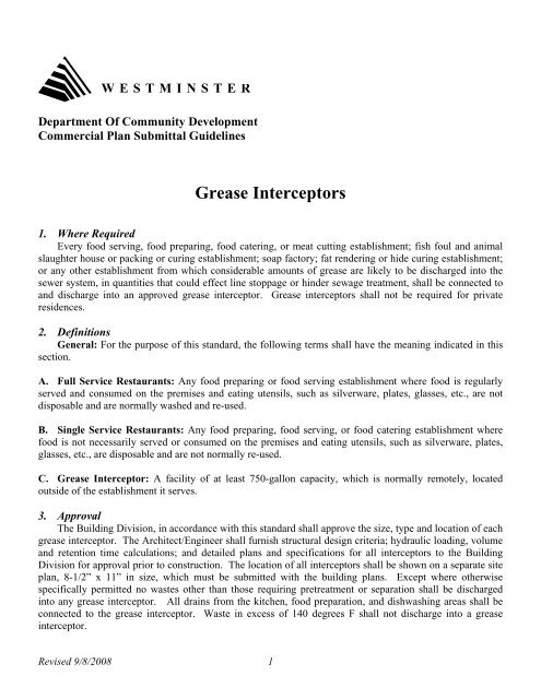
Grease Interceptors
Grease Interceptors
Grease Interceptors

You also want an ePaper? Increase the reach of your titles
YUMPU automatically turns print PDFs into web optimized ePapers that Google loves.
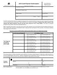
8. <strong>Grease</strong> TrapsA. General: When, in judgment of the Chief Building Official, it would be impractical or unnecessary toinstall a full-size grease interceptor outside the building due to the nature or relative size of a foodestablishment, the installation of an in-line grease trap may be approved. Expense shall not be consideredsufficient reason to waive the requirements for full-size grease interceptors.B. Approval: Complete plans indicating the size and rating of the unit, pipe sizing, venting, location of theunit, and location of flow control devices shall be submitted to the Building Division for approval prior toconstruction.C. Design: Each grease trap shall be so installed and connected that it will be readily accessible forcleaning and inspection at all times. <strong>Grease</strong> traps shall be constructed of durable materials satisfactory to theBuilding Official and shall have a full size gas tight cover, which can be readily removed. Each grease trapshall have a water seal of not less than 2” in depth or the diameter of its outlet, whichever is greater. Nosingle in-line grease trap shall serve more than two separate fixtures. <strong>Grease</strong> traps shall be installed andvented in accordance with the International Plumbing Code.D. Sizing: The minimum size of grease traps shall be based on the maximum rate of flow of all fixturesdischarging into the grease trap multiplied by a retention factor of 1.5 minutes. Table A on page 4establishes the maximum rate of flow, in G.P.M. for various pieces of kitchen equipment and plumbingfixtures which may require connection to the grease trap. No grease trap shall be installed with an approvedrate of flow less than 20 gallons per minute or a retention capacity of less than 40 lbs. Unless specificallyrequired or permitted by the Building Division, no garbage disposal or dishwasher shall be connected to ordischarged into any grease trap.Revised 9/8/2008 3
Table ATYPE OF FIXTUREFloor Drains:- discharging into interceptorsfor grease, oil, solids, etc.- discharging into non-vehiclewash sand & oil interceptors- discharging into vehicle washsand & oil interceptorsSinks:- commercial bar sinks- restaurant kitchen sinks(single compartment)- restaurant kitchen sinks(three compartment)- restaurant hand sinks- service sinks (mop sinks)Dishwashers:- up to 50 gal. capacity- over 50 gal. capacityGarbage Disposals:TRAP & TRAP ARM SIZE2”3”2”3” or 4”3” or 4”1-1/2”1-1/2”1-1/2”1-1/2”2”---RATE OF FLOW IN G.P.M.15202045601520401520204035Receptors:- the size and discharge rating of each indirect waste receptor shall be based on the total rated dischargecapacity of all fixtures, equipment, or appliances discharging therein.Note:The discharge capacity of fixtures or devices not shown in Table A shall be actual rated discharge capacity ofthe fixture or device.Revised 9/8/2008 4
TYPICAL GREASE INTERCEPTORWATER CAPACITY 300-3500 GALLONS2” min. VentsPipe Diameter Plus 2”PLAN VIEW2” min. VentsMay join 12” min. above gradeClean- out to gradeSECTIONGeneral Notes:1. These details are only intended to show conceptual / standard requirements for grease interceptors and are not intended to beused for construction. Design criteria and detailed construction drawings, stamped and signed by a Colorado RegisteredArchitect or Engineer, must be submitted to the Building Division for approval.2. All pipe and fittings must be approved soil pipe, 3” minimum in diameter, unless noted otherwise.3. Walls, bottom, and top of interceptor must be reinforced throughout with additional reinforcement around access openings asspecified by architect or engineer. All reinforcement shall have 1-1/2” min. cover to face of concrete.4. The architect or engineer must specify the thickness of walls, bottom, and top slab.5. Outlet pipe invert must be 2” lower than inlet.6. The Utilities Department must approve bolt down covers.7. Support brackets and clean-out plugs must be brass.8. Vent pipes may be joined 12” above grade minimum.Revised 9/8/2008 5