The Hydrographic product family - Kongsberg Maritime
The Hydrographic product family - Kongsberg Maritime
The Hydrographic product family - Kongsberg Maritime

You also want an ePaper? Increase the reach of your titles
YUMPU automatically turns print PDFs into web optimized ePapers that Google loves.
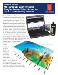
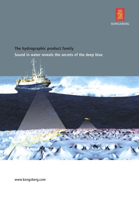
<strong>The</strong> hydrographic <strong>product</strong> <strong>family</strong><br />
Sound in water reveals the secrets of the deep blue<br />
www.kongsberg.com
<strong>The</strong> Hydrography <strong>family</strong>:<br />
Multibeam echo sounders<br />
Wide-swath systems<br />
Singlebeam echo sounders<br />
Our mission<br />
Maximizing performance<br />
by providing <strong>The</strong> Full Picture<br />
We shall earn the respect and recognition for our dedication to provide innovative and reliable marine electronics that ensure optimal operation at<br />
sea. By utlilising and integrating our technology, experience and competencies in positioning, hydroacoustics, communication, control, navigation,<br />
simulation, and automation, we aim to give our customers <strong>The</strong> Full Picture. <strong>The</strong> Full Picture yields professional solutions and global services that<br />
make a difference enabling you to stay ahead of the competition.<br />
Our philosophy<br />
Sidescan sonars<br />
Imaging Sonars<br />
Sub bottom profilers<br />
Synthetic Aperture Sonar<br />
Integrated solutions<br />
Our success depends on the success of our customers. Actively listening to our customers and truly understanding their needs, and then translating<br />
these needs into successful <strong>product</strong>s and solutions is central to achieving our goal. Our people are the key to our success and we empower them to<br />
achieve. Working together in a global network of knowledge, guided by our values, engenders innovation and world class performance. Every day<br />
we have to think a little differently, because every client is unique.<br />
We aspire to translate the imagination and dedication of our staff into successful technologies and solutions. Our commitment is to add value to<br />
your operations by providing you with <strong>The</strong> Full Picture.
In the forefront of technology<br />
<strong>Kongsberg</strong> <strong>Maritime</strong> is the major supplier of high quality marine electronics in<br />
the world, with <strong>product</strong>s ranging from underwater sensor systems to complex<br />
ship and process control systems for commercial vessels and oil rigs as well as<br />
autonomous underwater vehicles, sonars and instrumentation systems for<br />
fisheries, naval and scientific research vessels. <strong>The</strong> <strong>product</strong>s are designed,<br />
tested and produced to be reliable over a long time in the tough marine<br />
environment.<br />
<strong>Hydrographic</strong> survey ships and launches<br />
With the task of collecting accurate information about the seabed,<br />
hydrographic survey vessels must be equipped with instrumentation that is<br />
efficient, accurate, and reliable.<br />
<strong>The</strong> <strong>Kongsberg</strong> survey instrumentation solutions are adaptable to the<br />
different user requirements, through a broad range of sonars and echosounders.<br />
Real time data processing and visualization software gives the<br />
surveyors immediate information about the progress of work and the quality<br />
of the data that is being collected.<br />
Invisible sound makes everything visible<br />
Acoustic sound transmission represents the basic techniques for underwater<br />
navigation, telemetry, echosounders and sonar technology. Common for all is<br />
the use of underwater pressure wave signals that propagate with a speed of<br />
1500m/s through the water. When the pressure wave hits the sea bottom or<br />
another object, a reflected signal is transmitted back and detected. <strong>The</strong><br />
reflected signal contains information characterizing the reflected object. <strong>The</strong><br />
sea is far from an ideal transmission medium, with acoustic noise and multipath<br />
interference as some of the major concerns. With more than fifty years<br />
in the business, we have learned to master sound in water to reveal the<br />
secrets of the deep blue.<br />
Some images are courtesy of CHS and NOAA.<br />
3
Multibeam echo sounders (MBES) collect<br />
bathymetric soundings in a swath<br />
perpendicular to the ship track by<br />
electronically forming a series of transmit<br />
and receive beams in the transducer<br />
hardware which measure the depth to the<br />
sea floor in discrete angular increments or<br />
sectors across the swath (Hughes-Clarke,<br />
J.E., Mayer, L.A., and Wells, D.E., 1996).<br />
Singlebeam echo sounder<br />
Multibeam echo sounder<br />
Images: © J.E. Hughes Clarke, OMG/UNB<br />
4<br />
MULTIBEAM ECHO SOUNDERS<br />
<strong>Kongsberg</strong> <strong>Maritime</strong> has been a supplier of echo sounders for more than 60 years and<br />
of multibeam echosounders since 1986 and is recognized as the world’s leading<br />
supplier of Multibeam Echosounders for use in all water depths.<br />
Since the first multibeam system KM has been recognized as a dependable supplier of<br />
multibeam systems and a respectable numbers of systems have been delivered<br />
through out the years. All systems have quickly earned reputations for being reliable<br />
and with outstanding performances.<br />
All systems in our <strong>product</strong> range use digital techniques throughout the processing<br />
chain and have sophisticated bottom detection algorithms.<br />
What is a multibeam system?<br />
Multibeam bathymetry is based on the fact that more beams are better than one.<br />
<strong>The</strong>y map the seafloor by generating several hundred beams over a crosstrack profile<br />
for each ping, and each beam generates at least one depth sounding.<br />
While the platform sails forward the seafloor is covered with a dense pattern of<br />
soundings producing high-resolution bathymetry data and geo-referenced high<br />
resolution seabed imagery throughout the survey area and thus providing 100%<br />
coverage of the seafloor. Different models are offered for different water depth<br />
requirements and several versions of each model are available with different resolution<br />
capabilities.<br />
A typical multibeam system consist of four units, a transmit transducer, a receive<br />
transducer, a transceiver unit and an operator unit.<br />
<strong>The</strong> transmit transducer is long in the alongship direction and short in the athwart<br />
ship direction; enable the system to generate a swath of sound which is wide in<br />
athwart ship and narrow in the alongship direction. <strong>The</strong> receiver is wide in athwart<br />
ship direction and narrow in the alongship, enabling the system to receive the wide<br />
swath produced by the transmitter, but still have narrow beams in the along track<br />
direction.<br />
<strong>The</strong> sound generated by the transmit array, is reflected by the sea the seafloor at<br />
different angles and is received by the receiver transducer at slightly different times.<br />
All the signals are then processed by the transceiver unit, converted into depth values<br />
and plotted as a bathymetric map on the operator unit.<br />
Singlebeam echo sounder<br />
Images: © J.E. Hughes Clarke, OMG/UNB<br />
Multibeam echo sounder
Common features for all multibeam systems<br />
Listed below are common features which are incorporated in all our multibeam<br />
systems*. Many of these features are essential to be able to ensure a dense coverage of<br />
the seafloor to fulfill requirements set by IHO S-441) and LINZ2) even in foul weather<br />
condition.<br />
Sector transmission and stabilization<br />
Our multibeam systems apply sound velocity correction in real time. <strong>The</strong> basic algorithm<br />
performs a ray tracing process through the water column for each beam using an<br />
'intersection of cones' technique that is unique to the <strong>Kongsberg</strong> multibeam systems.<br />
It also computes the steered beam angles based on the surface sound speed – at the<br />
transducer. <strong>The</strong> result of this procedure will be a depth solution datagram that contains<br />
along-track, across-track, and reduced depth values for each beam.<br />
Sector transmission and stabilization<br />
Today most systems only do compensation of the data due to vessel roll and pitch<br />
movements. It is however essential also to do stabilization to give a smooth, dense<br />
coverage of the seafloor without any gaps or holes in the data, which might lead to loss<br />
of objects or seabed features. Stabilization of the system means that both the<br />
transmitter and the receiver beams are electronically steered according to the vessels<br />
movement. In foul weather conditions the spacing between soundings as well as the<br />
acoustic footprints can be set nearly constant over the swath in order to provide a<br />
uniform and high detection and mapping performance.<br />
Sector transmission means dividing the transmitter sector into smaller sections with<br />
different frequencies, which can be individually electronically steered.<br />
In shallow waters the systems generate up to 4 transmit sectors, while in deeper waters<br />
up to 8 transmit sectors are being utilized (system dependent). This enables several<br />
essential key-features; such as a very effective stabilizing for pitch and yaw-movements,<br />
use of multiple focal points when focusing on transmission, increased range<br />
performance and suppression of multi-bounce signals i.e. second surface return and<br />
other multiple echoes.<br />
Yaw and pitch stabilization are performed by tilting the different transmit sectors,<br />
while roll stabilization is done by the receiver beams.<br />
Vessel motions will not be any problem for the systems when applying active<br />
electronic stabilization.<br />
* Yaw stabilization and FM chirp, not available on EM 3002<br />
1) IHO, International <strong>Hydrographic</strong> Organization<br />
2) LINZ, Land Information New Zealand<br />
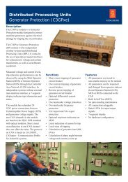
Without Yaw Stabilization.<br />
With Yaw Stabilization.<br />
© J.E. Hughes Clarke, OMG/UNB<br />
5
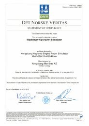
6<br />
High density signal processing:<br />
Standard mode - 256 soundings<br />
High density signal processing:<br />
High density mode - 400 soundings<br />
Images: © J.E. Hughes Clarke, OMG/UNB<br />
High density signal processing and beam focusing<br />
<strong>The</strong> horizontal resolution is much improved compared to previous models, due to the<br />
introduction of focused beams for both transmission and reception and the new high<br />
density signal processing technique.<br />
Near-field focusing is essential for retaining angular resolution. On reception this is<br />
done dynamically (focal point is shifted as function of time/range) and on transmit<br />
each sector will have independent focal points.<br />
Dual Swath<br />
In dual swath mode the system generates two transmit swath per ping. <strong>The</strong> result will<br />
be twice the number of soundings per ping giving a denser profile of the seabed even<br />
with a very narrow transmitter or when surveying at high speed.<br />
<strong>The</strong> main reason for using dual swath is to fulfill IHO special order requirement at<br />
ship speed of 8 knots with a 0.5 degree transmitter. Note that the dual swath is<br />
available in all configurations, enabling the survey speed to be increased and still<br />
maintaining the same dense alongship profile compared to half the speed without<br />
dual swath.<br />
With the high density mode the crosstrack resolution is improved, by reducing the<br />
footprint size to less than 25%. This can also be seen as synthetic sharpening of the<br />
beams and is a great achievement giving a nearly constant crosstrack physical size of<br />
sounding spot over the complete swath.<br />
Maintaining all beams in the swath<br />
In some applications or due to weather condition the user might want to reduce the<br />
swath width. If so, the systems will not cut-off the outer beams, but will maintain all<br />
beams in the new coverage sector set by the operator. Hence, both the resolution and<br />
the ping rate will increase. This is a unique feature for all systems from <strong>Kongsberg</strong> and<br />
very useful when surveying a wreck or feature on the seabed. <strong>The</strong> operator may also<br />
select a maximum coverage to ease the line planning in sloping terrain. <strong>The</strong> system will<br />
then run in an automatic mode and maintain all beams within the selected coverage.<br />
<strong>The</strong> full number of beams are maintained when the swath width<br />
is reduced.<br />
Backscatter draped as surface over the bathymetry
Extended coverage by use of chirp technology<br />
<strong>The</strong> use of new frequency independent hardware makes it possible to generate other<br />
signals than continuous wave (CW) pulses, like frequency modulated chirp (FM)<br />
waveforms for extended range performance and with pulse compression on reception.<br />
<strong>The</strong> use of FM gains approximately 15dB in signal-to-noise-ratio compared to CW.<br />
Seabed imagery and water column data<br />
In addition to the sounding data all systems produce high resolution backscatter data<br />
and water column data. Both can be logged simultaneously with bathymetric data.<br />
Multibeam Backscatter Data is equivalent to Sidescan Imagery.<br />
Backscatter draped as surface over the bathymetry<br />
EM 302 image: Plumes located in water depths between 1200 and 1900 meters and observed<br />
to rise to about 500 meters making their heights between 700 - 1400 meters.<br />
Images courtesy of NOAA Office Marine and Aviation Operations.<br />
Functionality to limit mammal harassment<br />
Our medium and low frequency system can be set in a flexible soft start mode as a<br />
possible means of inducing marine mammals to leave the area of high intensity sound.<br />
7
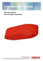
GeoSwath Plus data Plymouth.<br />
UK, data collected for nautical charting<br />
GeoSwath Plus data<br />
Glomma River in Norway.<br />
Data courtesy of NGU<br />
8<br />
Wide swath bathymetry system<br />
<strong>Kongsberg</strong> <strong>Maritime</strong> acquired GeoAcoustics in 2008. <strong>The</strong> company was already then<br />
well established and produced proven sidescan systems, sub-bottom profilers and wide<br />
swath bathymetry systems.<br />
What is a wide swath system?<br />
A wide swath bathymetry system is also called by several other names, “phase<br />
measuring bathymetric sonar system”, “interferometric multibeam” or “bathymetric sidescan<br />
system”.<br />
Swath bathymetry systems use two different technologies to obtain the bathymetry<br />
across the swath. A multibeam uses a beam forming technology while a wide swath<br />
system uses phase comparison techniques or interferometry. However, both systems<br />
produce the same result; a dense bathymetry map of the seafloor with additional<br />
information on backscatter strength of the seafloor.<br />
Data from the GeoSwath Plus has been accepted as meeting strictest IHO standards,<br />
and been included in UKHO Nautical Charts.<br />
<strong>The</strong> relative phase delay between the receive staves is decoded to give the angle of<br />
return of the sonar signal and the range. Each sonar ping provides a range series of<br />
angles to the seafloor. Two questions are often raised with the phase measurement<br />
technique: the issue of simultaneous returns from two features at different angles and<br />
the lower data density under the transducers. <strong>The</strong> keys to overcoming these are the<br />
short pulse length, rapid phase measurements and very low noise electronics used in the<br />
GeoSwath Sonar.<br />
A port and starboard ping together give the seafloor profile under the vessel and a<br />
series of pings taken as the vessel moves along the survey track gives the swath of<br />
soundings.<br />
Multi-element receive array measuring phase differences. In the GeoSwath Plus case the<br />
primary array consists of two transducers mounted to a “V” plate. Each transducer<br />
contains multiple ceramic staves:<br />
Bottom stave is transmitter, multiple receive elements.
Phase measuring systems are very <strong>product</strong>ive in the shallow water<br />
environment, where they cover a wide area with a single swath and<br />
simultaneously acquire true geo-referenced side scan data.<br />
GeoSwath Plus data 3D view – Simultaneous acquisition of wide swath bathymetry and geo-referenced side scan data.<br />
9
10<br />
SYSTEMS FOR ALL SURVEY APPLICATIONS<br />
For shallow water surveys, inspection, ROV and<br />
AUV applications<br />
Good knowledge of shallow water bathymetry is vital to a wide range of marine activities.<br />
Surveys for navigation channels, ports and harbors, lake and dam management,<br />
environmental mapping, marine archaeology, marine construction, cable landfalls and<br />
hydrodynamic modeling all rely on accurate and detailed information on the water depth.<br />
Such surveys are mainly in waters less than 50m deep, with many in the zone from 20m<br />
water depth to the shoreline.<br />
High resolution, complete coverage, high accuracy, and detection of all significant<br />
features are particularly important in these circumstances.<br />
Recently published survey specifications emphasize these points, and pay particular<br />
attention to the shallow water.<br />
Examples of this includes the International <strong>Hydrographic</strong> Organization (IHO) Special<br />
Publication S-44 Edition 5, the LINZ specification and the United States Army Core of<br />
Engineers (USACE) <strong>Hydrographic</strong> Surveying Standards.<br />
A sonar system for shallow water surveys must also be able to operate on shallow draft<br />
vessels, be easy to deploy and use, and reduce the time to produce a deliverable chart.<br />
EM 2040 – From shallow to very high resolution inspection surveys<br />
<strong>The</strong> EM 2040 is the latest generation of multibeam models and is developed to give the<br />
user the outmost performance through a very high resolution and a flexible design. It has<br />
been developed to meet the strictest requirements in the survey industry and is a true<br />
“all-in-one” tool with its wideband operation. <strong>The</strong> bandwidth used by the system is more<br />
than 75kHz with three sectors. With dual swath six sectors are used.<br />
<strong>The</strong> system is the ideal tool for any operation from shallow water surveys to very high<br />
resolution inspections, onboard survey launches or any vessels of opportunities, hull or<br />
over the bow installation to ROV and AUV applications.<br />
<strong>The</strong> system has an operating range from 0.5 to 450m relative to the transducer with a<br />
maximum swath width of 750m or 140 degrees for a single system. A dual system will<br />
have a coverage of up to 800m or 200 degrees, which is 10 times the water depth.<br />
<strong>The</strong> system can be delivered with<br />
different transducer sizes for different<br />
resolutions.<br />
A single system consists of one<br />
transmitter and one receiver, while a<br />
dual system consist of one transmitter<br />
and two receivers.<br />
<strong>The</strong> transducers are depth rated to<br />
6000m as standard.
EM 3002 – From shallow to high resolution surveys<br />
<strong>The</strong> EM 3002 is a well proven multibeam for shallow water and for high resolution<br />
surveys. <strong>The</strong> operating range is from 0.5m to more than 250m, with a maximum<br />
coverage of 200m (dual system). Due to its small sonar heads it is ideal for permanent or<br />
portable deployment on launches or any vessels of opportunity either in hull or over the<br />
bow, but also for installation on ROV and AUV. <strong>The</strong> system can be delivered either with<br />
one sonar head or with two for increased coverage to more than 200m or almost to the<br />
water surface. Two different sonar heads are available, 500m and 1500m depth rated.<br />
�������<br />
�����<br />
��������<br />
��������<br />
������������������<br />
�������������������<br />
��������������������������������<br />
�������<br />
�����<br />
�������������������<br />
��������������������<br />
���������������������<br />
���������������<br />
�����������������������<br />
��� ��� ��� ����� ������� �<br />
����� � ���<br />
�� ������ ��<br />
������� � �<br />
����� ��������<br />
��<br />
Breakwater. Courtesy of Port of Bridgetown, Barbados<br />
���������������<br />
�����������<br />
������������������<br />
����<br />
�������������������<br />
�����������������������<br />
���������������������������������<br />
��������<br />
���������� �����������������<br />
����������<br />
���������<br />
HMAS Brisbane. Courtesy of MSQ, Australia<br />
11
12<br />
GeoSwath Plus set-up.<br />
GeoSwath Plus – For shallow surveys with wide swath requirements<br />
GeoAcoustics GeoSwath Plus is the market leader in the phase measuring bathymetric<br />
sonar technology and is a well proven system.<br />
<strong>The</strong> system simultaneously acquires swath bathymetry and true side scan data with a<br />
swath coverage of up to 12 times the water depth. This makes the GeoSwath Plus a very<br />
<strong>product</strong>ive survey tool for the shallow water environment producing bathymetry data<br />
shown to match IHO S-44 special order accuracy.<br />
Three different frequency versions are available, 125, 250 and 500kHz with depth<br />
performances of 200, 100 and 50m respectively to match the survey requirements.<br />
<strong>The</strong> system can be deployed on dedicated survey vessels as well as vessels of opportunity<br />
in versatile over-the-side, bow, moon pool or hull mount arrangements.<br />
<strong>The</strong> standard system comprises the rugged but light weight sonar head and a dedicated<br />
deck unit including a PC running the GeoSwath Plus software package that offers all<br />
features from data acquisition to the <strong>product</strong>ion of the final bathymetry and side scan<br />
data <strong>product</strong>s. Alternatively interfaces to all major hydrographic survey software suites<br />
are available.<br />
A compact version, GeoSwath Plus Compact, has been<br />
designed for small boat or even jet-ski operations.<br />
<strong>The</strong> deck unit components are housed in a rugged<br />
splash proof box that links to a laptop computer from<br />
which the system is operated. It uses 24 V power and<br />
only draws 40 W.<br />
Payload modules of the GeoSwath Plus with depth ratings of<br />
up to 4000m are readily integrated into any AUV or ROV.<br />
With data coverage of up to 12 times the vehicle’s fly height<br />
and its low power consumption it offers survey efficiency for<br />
all military and civil survey applications.<br />
GeoSwath Plus AUV version, installed on an REMUS-100 AUV.
Medium to deep water applications<br />
EM 710 – for medium water depths<br />
<strong>The</strong> EM 710 is a well proven and flexible multibeam for high resolution surveys from<br />
shallow to medium water depths. <strong>The</strong> operating range is from 2m to more than 2000m,<br />
with a maximum swath width of 2000m. It comes with a choice of different beamwidths,<br />
and several versions are offered with different range performances.<br />
<strong>The</strong> EM 710 is well suited for surveys requiring performance according to IHO S-44 special<br />
order and order 1. <strong>The</strong> versions with the highest resolution are suited for detection of<br />
objects on the seafloor according to the LINZ and IHO special order requirements.<br />
All features like stabilization for pitch, roll and yaw, but also high density signal processing<br />
and equidistant pattern are necessary for reliable object detection, and thus a standard for<br />
all systems.<br />
A portable model is available for the 2x2 degrees option with a smaller transceiver cabinet.<br />
Ice reinforced versions of the transducers are available for operation in ice conditions.<br />
EM 710 sandwaves at Trial Island (Vancouver Island, British Columbia, Canada)<br />
2 or 4<br />
EM 710 image of MV Hoegh Aigrette<br />
at 25-42m depth.<br />
Courtesy of UK <strong>Maritime</strong> and Coastguard Agency. Data<br />
acquisition, processing and visualisation by Fugro OSAE.<br />
POWER Operator<br />
Station<br />
5, 10 or 20<br />
Receive transducer array<br />
Transceiver<br />
Unit<br />
Interfaces (serial and<br />
Ethernet):<br />
Sound Speed probe<br />
Tide<br />
Single beam echo<br />
sounder depths<br />
Serial interfaces:<br />
Positioning systems<br />
Attitude (roll, pitch and heave)<br />
Heading<br />
Clock<br />
Special interfaces:<br />
Trigger input/output<br />
Clock synchronization<br />
Supply voltage:<br />
115 or 230 Vac 50/60 Hz<br />
(Cd021601a)<br />
Transmit transducer array<br />
Remote Control<br />
(Optional)<br />
13
14<br />
EM 302 – Swath coverage at 6553m<br />
EM 710 image of Portland-Weymouth Bay 8-40m depth, 4 x 8 km area.<br />
Courtesy of UK <strong>Maritime</strong> and Coastguard Agency. Data acquisition, processing and visualisation by Fugro OSAE.<br />
EM 302 – ocean basins<br />
<strong>The</strong> EM 302 is a well proven multibeam for surveys starting at depths of 10m to beyond<br />
the continental rises, including the shallower ocean basins, down to 7000m. <strong>The</strong><br />
maximum achievable swath width is about 8km. Small transducers and compact<br />
electronics makes the installation easy and the system accuracy is well within the IHO<br />
standards. <strong>The</strong> system is offered with different array sizes and beam widths.<br />
To protect the transducers a special ice-window can be delivered. <strong>The</strong> ice-window is<br />
withstanding a pressure of 26 tons per 10 x 10 inches, and is delivered with a certificate.<br />
<strong>The</strong> system can be easily integrated with a sub-bottom profiler, the SBP 300, by adding<br />
an extra transmit transducer.<br />
Optional: Preamplifier & SBP<br />
SBP 300<br />
Transceiver<br />
Unit<br />
SBP 300<br />
Tx/Rx<br />
Junction Box<br />
(CD021927)<br />
Preamplifier<br />
Unit<br />
Preamplifier<br />
Unit<br />
SBP 300<br />
Transmit transducer array<br />
EM 302 system layout<br />
Remote On / Off<br />
Internal<br />
Ethernet<br />
Receive transducer array<br />
PEOW<br />
R<br />
Operator<br />
Station<br />
Ethernet<br />
Interfaces:<br />
Positioning systems<br />
Attitude (roll, pitch and heave), velocity<br />
Heading<br />
Clock<br />
Trigger input/output<br />
Clock synchronization<br />
TX Junction<br />
Box no.1<br />
Transmit transducer<br />
for 1, 2 and 4 degree<br />
Interfaces:<br />
Sound Speed Sensor<br />
Tide<br />
Center depth output<br />
Ethernet and serial lines<br />
(data i/o)<br />
TX Junction<br />
Box no.2<br />
Transmit transducer<br />
for 0.5 degree
EM 302 bathymetry differentiated sand ripples as small as 15-30cm in 100m of water.<br />
Data Courtesy of NOAA, Okeanos Explorer.<br />
EM 302 survey by Okeanos Explorer, depth range 120-845m.<br />
Data Courtesy of NOAA.<br />
15
Internal<br />
Ethernet<br />
16<br />
Transceiver<br />
Unit<br />
EM 122<br />
POWER Operator PC<br />
Interfaces:<br />
Positioning systems<br />
Attitude (roll, pitch and heave)<br />
Heading<br />
Clock<br />
Trigger input/output<br />
Clock synchronization<br />
Preamplifier<br />
Unit<br />
Receive transducer array<br />
EM 122 system layout<br />
Interfaces:<br />
Sound Speed Sensor<br />
Tide<br />
Center depth output<br />
Ethernet and serial lines (data i/o)<br />
Ethernet<br />
Remote Control<br />
TX Junction<br />
Box no.1<br />
TX Junction<br />
Box no.2<br />
Transmit transducer array<br />
EM 122 – full ocean depth<br />
<strong>The</strong> EM 122 is a well proven multibeam for full ocean depth surveys, suited for detailed<br />
seafloor mapping from less than 50 meters up to 11000 in the ocean. Up to 30-35km<br />
swath width is achievable and from customer acceptance tests it has been proven that<br />
the system can achieve coverage of more than 40 km under favorable conditions. <strong>The</strong><br />
system accuracy is well within the IHO standards.<br />
To protect the transducers a special ice-window can be delivered. <strong>The</strong> ice-window is<br />
withstanding a pressure of 26 tons per 10 x 10 inches, and is delivered with a certificate.<br />
<strong>The</strong> system can be easily integrated with a sub-bottom profiler, the SBP 120, by adding<br />
an extra transmit transducer.<br />
EM 122 swath coverage at 10788m water depth.<br />
Data courtesy of U.S. Naval Oceanographic Office (NAVOCEANO).<br />
EM 122 survey of the Gakkel Ridge by the Swedish Icebreaker ODEN, depth 4000m.<br />
Data courtesy of Stockholm University.
Technical specifications for multibeam systems<br />
System EM 2040 EM 2040 EM 3002S EM 3002D EM 710 EM 302 EM 122<br />
with Dual RX<br />
Operating frequency 200 to 400 200 to 400 300 300 70 to 100 30 12<br />
(kHz)<br />
Range (m) 0.5 to 500 0.5 to 500 0.5 to 250 0.5 to 250 3 to 2000 10 to 7000 50 to 11000<br />
Maximum coverage >700m >800m 300m >300m 2500m >8km >30km<br />
(cold sea, gravel) 140dg 200 dg 130 dg 200 dg 140 dg 150dg 150dg<br />
5.5x water depth 10x water depth 4x water depth 10x water depth 5.5x water depth 5.5x water depth 6x water depth<br />
Beamwidths TX:0.5, 1 TX:0.5, 1 TX: 1.5 TX: 1.5 TX: 0.5, 1, 2 TX: 0.5, 1, 2, 4 TX: 0.5, 1, 2<br />
(degrees) RX: 1 RX: 1 RX: 1.5 RX: 1.5 RX: 1, 2 RX: 1, 2, 4 RX: 1, 2, 4<br />
(at 300kHz) (at 300kHz) (at 100kHz)<br />
System accuracy >2cm >2cm ~ 5-10 cm ~ 5- 10 cm 0.2 % x 0.2 % x 0.2 % x<br />
water depth water depth water depth<br />
Maximum number of Up to 800 Up to 1600 254 508 Up to 800 Up to 864 Up to 864<br />
soundings per ping<br />
Pulse form CW & FM CW & FM CW CW CW & FM CW & FM CW & FM<br />
Pulse length 25us-12ms 25us-12ms 50us-400us 150us-400us 150us-120ms 0.7ms - 200ms 2ms - 100ms<br />
Max pingrate (Hz) 50 50 40 40 >30 >10 >5<br />
Transducer depth rating 6000m 6000m 500m, 1500m 500m, 1500m 250m NA NA<br />
Ice protection N/A N/A N/A N/A Yes Yes Yes<br />
Technical specifications for wide swath systems<br />
System GeoSwath Plus GeoSwath Plus GeoSwath Plus<br />
125kHz 250kHz 500kHz<br />
Operating frequency (kHz) 125kHz 250kHz 500kHz<br />
Range (m) 0-200 m 0-100 m 0-50 m<br />
Maximum coverage 12x water depth 12x water depth 12x water depth<br />
(cold sea, gravel) Up to 780m Up to 390m Up to 195m<br />
Beamwidths (degrees) Along track Along track Along track<br />
0.85° 0.75° 0.5°<br />
Maximum number of soundings per ping > 5000 raw data points > 5000 raw data points > 5000 raw data points<br />
Pulse form CW CW CW<br />
Pulse length 128 to 896 µs 64 to 448 µs 32 to 224 µs<br />
Max ping rate (Hz) 30 30 30<br />
Transducer depth rating 4000m 4000m 4000 m<br />
17
18<br />
SINGLE BEAM ECHO SOUNDERS<br />
<strong>Kongsberg</strong> <strong>Maritime</strong> has produced single beam echo sounder systems since 1957 with<br />
the first hydrographic single beam system in 1981, named EA 200.<br />
Our hydrographic single beam echo sounders are available as single or up to 4 acoustic<br />
frequencies and can be adapted to many different applications.<br />
What is a single beam system?<br />
A single beam echosounders uses one common transducer for transmitting a pulse and<br />
for receiving of the returning echo. <strong>The</strong> sounder will ensonify a small area underneath<br />
the boat in one single beam. <strong>The</strong> time different between the transmit sound and its<br />
echo is used to calculate the water depth beneath the boat.<br />
EA series<br />
<strong>The</strong> EA series of single beam echosounder are one of the most comprehensive and high<br />
performance hydrographic single beam echo sounders available in the marked today,<br />
with a very easy and user friendly operating software. All our single beam echo<br />
sounders use Microsoft Windows based operating software. A comprehensive operator<br />
manual is available as online help, always there when you need it. All echo data can be<br />
stored as files: bitmap, sample data (for replay), depth data or sidescan data.<br />
EA 400 – for shallow water applications<br />
<strong>The</strong> EA 400 consists of a transducer, a General Purpose Transceiver (GPT) unit and a<br />
laptop. <strong>The</strong> system works with upto four simultaneous frequencies in the range of<br />
33–710kHz. All channels are independently controlled, but with simultaneous<br />
transmission. In addition to raw data storage the system can store bitmap data, depth,<br />
position, heave and annotations. <strong>The</strong> raw data can be replayed later for generation of<br />
addition data.<br />
<strong>The</strong> GPT has a 160dB dynamic range with a non-saturating receiver, allowing the TVG<br />
to be applied in software.<br />
In addition to displaying the vertical depth a common option is to add two sidescan<br />
transducers for high resolution sidescan. In addition a low frequency transducer can be<br />
used for sub-bottom profiling (15kHz).<br />
Several software packages from 3rd party vendors can be used simultaneous for<br />
displaying electronic navigational charts.
(CD24111)<br />
EA 400SP – portable and splash-proof system for shallow water<br />
<strong>The</strong> EA 400SP is a portable and splash-proof version of the EA 400 hydrographic echo<br />
sounder, housed in a protected suitcase.<br />
It is compact which makes it the perfect portable echo sounder for surveying in shallow<br />
water depths in small, open boats or vessels of opportunity. <strong>The</strong> system consists of a<br />
computer and a General Purpose Transceiver (GPT) housed in a rugged and splash-proof<br />
protective suitcase with IP grade 65 and with a window. <strong>The</strong> computer can be delivered<br />
as a standard laptop or a rugged IP rated notebook and can be configured to operate on<br />
single or dual frequencies between 38 and 710kHz. In this range the<br />
side-scan transducers 120 and 200Khz are also available.<br />
As standard, the EA 400SP unit operates on a DC voltage.<br />
EA 600 – for deep water applications<br />
EA 600 supports lower frequencies than the EA 400 and is suited for deep water<br />
operation. Frequency range is from 10kHz to 710kHz.<br />
<strong>The</strong> system can have several pulses in the water at the same time, to maintain a high<br />
ping rate in deep water environment. It also has functionality for accurate depth tracking<br />
of acoustic pingers.<br />
S IMRAD GPT<br />
Alternative 1<br />
Colour LCD display with built-in CPU,<br />
One transceiver unit with one or<br />
two transducers.<br />
S IMRAD GPT<br />
HUB<br />
General Purpose<br />
Transceivers<br />
(GPT)<br />
Alternative 2<br />
S IMRAD GPT<br />
Colour LCD display with built-in CPU,<br />
One or two transceivers units<br />
for dry area environment (IP40), each<br />
with one or two transducers.<br />
EA 400 and EA 600 system layout, different configurations alternatives.<br />
Alternative 3<br />
EA 400 Splash proof version.<br />
Alternative 4<br />
Colour LCD display with built-in CPU. Colour LCD display with built-in CPU.<br />
One or two transceivers installed in<br />
One or two transceivers, each<br />
housing for rough area environment (IP55), with one or two transducers.<br />
each with one or two transducers.<br />
19-inch rack installation.<br />
19
20<br />
EA MCU – Multi channel unit<br />
<strong>The</strong> EA MCU is a hydrographic sweep system specifically designed for use in channels,<br />
rivers and other shallow bodies of water. Its precise depth and bottom detection<br />
capabilities provide detailed bottom imagery.<br />
This compact multi-channel echo sounder, based on Microsoft Windows XP operating<br />
system, can simultaneously monitor both depth and bottom profile. All data is shown in<br />
real time using a color-coded waterfall display which graphically represents areas of<br />
common depth using different colors.<br />
<strong>The</strong> EA MCU readily detects obstacles and objects on the bottom. Even when targets are<br />
covered by mud or sediment, spikes in the waterfall display and abrupt changes in<br />
baseline echogram data disclose their locations. By using 15kHz low frequency<br />
simultaneously, sub-bottom penetration data is achieved.<br />
<strong>The</strong> display can view all echograms for quality use.<br />
<strong>The</strong> EA MCU sweep system has several advantages including:<br />
• Bottom detection capabilities specially suited for use in shallow water<br />
• Consistent and accurate data over an entire sweep<br />
• Replay of raw data<br />
• Simple to configure the x,y, z coordinates of the transducers<br />
• Transducer mode, parameter and display settings stored on the computer’s hard drive<br />
• Storing of real time sound velocity (SV) sensor<br />
• Very high pingrate (64 Hz @ 4 m) guaranties hits even<br />
on very small targets<br />
• Simultaneous transmit on all transducers<br />
• Interference between neighboring transducers is<br />
reduced to zero by using alternate frequencies<br />
(180, 220, 180,..)
SIDE SCAN SONAR SYSTEMS<br />
Dual Frequency Side Scan Sonar system<br />
<strong>The</strong> GeoAcoustics towed dual frequency side scan sonar systems are the ideal tool for<br />
seabed feature mapping, offering high quality results in a simple and reliable package.<br />
<strong>The</strong> system consists of a deck unit and a tow fish, allowing positioning the system at an<br />
ideal distance to the target. <strong>The</strong> system offers dual frequency operation of 114kHz and<br />
410kHz, allowing for wide area coverage and very high resolution surveys and it can be<br />
deployed down to 2000 m water depth with cable<br />
length up to 7000 m.<br />
For best results the tow fish is deployed at a height<br />
above the seafloor of 10% of the expected coverage.<br />
<strong>The</strong> versatility, ease of operation and reliability has<br />
made it a popular choice for navies and commercial<br />
survey companies alike.<br />
A range of systems are available to suit different<br />
survey applications.<br />
Side Scan tow fish<br />
Side Scan data.<br />
21
22<br />
6589900<br />
6589800<br />
ECHO SOUNDER WITH COMBINED SIDE SCAN<br />
AND DEPTH SOUNDINGS<br />
<strong>The</strong> side-looking sonar is available for the EA 400, EA 400SP and EA 600 hydrographic<br />
echo sounders, uses frequencies of 120 and 200kHz and is available in a single and dual<br />
version (two transducers). By using a side scan sonar transducer, these echo sounders can<br />
produce a side-looking image on the side of the vessel the transducer is located. <strong>The</strong> system<br />
is hull mounted or over-the-side boom mounted side scan transducer(s) to survey shallow<br />
areas such as harbors, rivers and canals. This eliminates the need for a towed side scan<br />
sonar or similar device. Another advantage is that fixing the correct geographic location of<br />
detected objects is made simple and more precisely. It is also possible to allocate one or<br />
two vertical channels to normal echo sounding in addition to dual acoustic imaging.<br />
Alternative 1 Alternative 2 Alternative 3<br />
SWITCH<br />
GPT<br />
38/200kHz<br />
Side looking 200kHz<br />
582600 582700 582800<br />
582600 582700 582800<br />
Geo-referenced side scan sonar imagery.<br />
EA 400 dual 200kHz side scan.<br />
GPT<br />
200/200kHz<br />
GPT<br />
38/200kHz<br />
Combi 38/200kHz<br />
Side looking 200kHz<br />
Side looking 200kHz Combi 38/200kHz<br />
EA 400 side scan, alternative configurations<br />
L0003-D20090512-T085757-EA400-G1x1-Mean-port<br />
L0003-D20090512-T090123-EA400-G1x1-Mean-port<br />
L0003-D20090512-T090449-EA400-G1x1-Mean-port<br />
L0003-D20090512-T090813-EA400-G1x1-Mean-port<br />
L0003-D20090512-T091139-EA400-G1x1-Mean-port<br />
:<br />
:<br />
Scale<br />
1 1000<br />
<strong>Kongsberg</strong> <strong>Maritime</strong> GmbH<br />
22525 Hamburg<br />
Hellgrundweg 109<br />
Horten Bay<br />
Test 200 kHz Sidescan<br />
Rocks -<br />
Chart - Nr.<br />
1-1000<br />
Details of survey area<br />
Status of Position DGPS<br />
Status of Height<br />
Datum UTM<br />
Details of Survey<br />
Date of first survey 12.05.2009<br />
Date of last survey 12.05.2009<br />
Vessel Pingeline<br />
Position Sensor<br />
Depth Sensor<br />
Depth Frequence<br />
Sidescan Port Frequence 200 kHz<br />
Sidescan Star Frequence<br />
Heading Sensor<br />
Details of Product<br />
Date of Processing<br />
Chart generated at 16.12.2009<br />
Producer UF<br />
Exclude of liability<br />
printed with SSM version 1.5.1.3<br />
HUB<br />
Side looking 200kHz<br />
GPT<br />
200/200kHz<br />
Side looking 200kHz
UNDERWATER INSPECTION USING IMAGING SONARS<br />
MS 1000 Scanning Sonar<br />
<strong>The</strong> visualization of underwater structures using imaging sonar heads is essential for<br />
many underwater applications and engineering projects. <strong>The</strong> MS 1000 Scanning<br />
Sonar can be used to perform inspection and investigation of structures and targets<br />
on the seabed (e.g. shipwrecks, piles) as well as man-made structures (e.g. bridges,<br />
jetties, wharves, offshore oil stations etc.) that need to be charted and their<br />
condition needs to be inspected for navigation safety purposes.<br />
<strong>The</strong> MS 1000 Scanning Sonar Processor is a Windows-based application and can be<br />
configured to control the complete digital line of <strong>Kongsberg</strong> Mesotech’s scanning<br />
sonar, altimeter, and bathy sensor <strong>product</strong>s via industry-standard telemetry protocols.<br />
Dual transducer imaging sonar head<br />
<strong>The</strong> 1171 Series of sonar heads have been developed<br />
to meet the requirements for deep ocean<br />
applications and are designed to produce high<br />
resolution scanning sonar images.<br />
<strong>The</strong> new sonar heads have reduced size and weight<br />
while providing high level of data quality. <strong>The</strong> dual<br />
transducer design allows optimized operational<br />
configuration for both long range obstacle avoidance and shorter range<br />
imaging detail.<br />
<strong>The</strong> transducer is protected within an oil-filled, pressure compensating dome.<br />
<strong>The</strong> telemetry is RS485 and RS232 compatible and is automatically sensed<br />
and configured at start up to match the telemetry link used.<br />
Documentation of aircraft wreckage and shipwrecks using <strong>Kongsberg</strong> Mesotech’s scanning sonar<br />
Aircraft wreckage.<br />
Courtesy of Peter Diving, Russia<br />
Shipwreck.<br />
PC<br />
Courtesy of Brian Abbott, Nautilus Marine Group<br />
KONGSBERG<br />
POWER<br />
Tx<br />
Rx<br />
HIGH VOLTAGE MS 1000 INTERFACE<br />
WWII shipwreck at 40m.<br />
Courtesy of Tuukritdööde Oü Commercial Diving, Estonia<br />
23
24<br />
SUB-BOTTOM PROFILERS<br />
SBP-120 and SBP-300 Integrated sub-bottom profilers<br />
<strong>The</strong> SBP-120 and SBP-300 is an optional hull mounted extension to the highly acclaimed<br />
EM 122 and EM 302 multibeam echosounders. <strong>The</strong> primary application of the SBP is to<br />
identify, characterize and measure layers of sediment or rock under the seafloor. All<br />
systems have excellent penetration and high<br />
resolution. <strong>The</strong>y cover all depth ranges from shallow<br />
waters to full ocean depth.<br />
<strong>The</strong> receiver transducer array of the EM 122 and<br />
EM 302 is a wide-band system and by adding a<br />
separate low frequency transmitter transducer,<br />
electronic cabinet and operator station the EM 122<br />
and EM 302 can be extended to include sub-bottom<br />
profiler capacity. Both system have electronic roll,<br />
pitch and heave stabilized beams.<br />
<strong>The</strong> systems have significantly reduced beam widths<br />
SBP 120/300 system layout<br />
compared to conventional sub-bottom profilers<br />
which is obtained by one linear transmit array<br />
mounted along the vessel keel and one linear hydrophone array shared with the EM 122<br />
or EM 302, mounted orthogonally to the keel.<br />
Using a large transmit array increases the source level due to injection of more power<br />
without any risk for cavitations and increases the directivity of the transmitter, which also<br />
improves the suppression of acoustic noise. Because the transmit beam is wide across-track<br />
and all hydrophones are sampled individually the SBP makes a fan of 11 narrow beams<br />
across-track per ping inside a 30° sector. This multibeam capacity of the SBP is useful for<br />
actually finding of the specular returns in rough terrain, resolving lateral specular returns<br />
in rough terrain, detecting buried objects and obtaining<br />
information about the angular response of sediments in the<br />
seafloor. All beams are electronically stabilized for roll and<br />
pitch movements; they can also be steered to take into<br />
account the bottom slope. Sound velocity correction is also<br />
applied.<br />
<strong>The</strong> transmit waveform is a linear FM chirp ranging from<br />
2.5 - 7kHz, providing a maximum vertical resolution of<br />
approximately 0.3 milliseconds. In addition the system can<br />
use other pulses like CW, hyperbolic chirp and Ricker.<br />
A high constant ping rate can be maintained even in deep<br />
waters with a multi-pulse mode available (for generating<br />
several pulses in the water). <strong>The</strong> system can be operated in a<br />
synchronised mode by running simultaneously with the EM<br />
SBP 120 survey of West-Central Okinawa Trough.<br />
122 or EM 302 multibeam echo sounders. Systems are<br />
Data courtesy of NAVOCEANO.<br />
offered as a three, six and twelve degree transmit system.
Geo Pulse and GeoChirp Sub-Bottom Profilers<br />
GeoAcoustic Sub-Bottom Profilers have versatile deployment options, towed, over-the-side<br />
or hull mounted. <strong>The</strong>y can be found on small survey launches in shallow water<br />
environments as well as ocean going vessels for deep water operations.<br />
GeoPulse<br />
<strong>The</strong> GeoPulse is the survey industry’s standard Sub-Bottom<br />
Profiler pinger system.<br />
Its proven success is due to its reliability, ruggedness, ease of<br />
operation and flexibility.<br />
Sub-Seabed structures are delineated using reflections from a<br />
selectable single frequency multi-cycle high power signal.<br />
GeoPulse data, Lake Chala, Kenya.<br />
Data courtesy of Renard Centre of Marine Geology,<br />
Gent, Belgium.<br />
GeoPulse Towed version.<br />
GeoChirp II<br />
<strong>The</strong> GeoChirp II delineates the sub-surface using<br />
reflections from the frequency modulated source<br />
signal. Due to chirp pulse compression and digital<br />
signal processing techniques it achieves deep<br />
penetration, whilst attaining high resolution.<br />
<strong>The</strong> operator can choose from a range of<br />
waveforms, or program his own signal, depending<br />
on the survey task.<br />
<strong>The</strong> Sub-Bottom Profilers can be combined with<br />
the Dual Frequency Side Scan Sonar System into a<br />
single shallow- or deep-towed vehicle that easily<br />
can interface to a towed magnetometer to<br />
complete the survey suite.<br />
GeoChirp II towed version.<br />
25
Synch.<br />
signals<br />
VRU (rs422/232)<br />
-roll<br />
-pitch<br />
-heave<br />
26<br />
Remote On/Off<br />
PS 18<br />
Transceiver<br />
Unit<br />
Internal<br />
Ethernet<br />
Interfaces<br />
- Ethernet (external)<br />
- Navigation system<br />
- Depth and slope<br />
Transmit/receive<br />
transducer array<br />
Operator Station<br />
TOPAS PS 18 and PS 40 (TOpographic PArametric Sonar)<br />
Both the PS 18 and PS 40 are parametric Sub-bottom Profilers designed to do highresolution<br />
sub-bottom profiling and object detection. <strong>The</strong> PS 18 operates in water depths<br />
from about 20 meters to full ocean depth, while the PS 40 is design to operate from less<br />
than 5 meters to more than 1000 meters water depth.<br />
Both systems are hull mounted with electronic roll, pitch and<br />
heave stabilized beams, which makes them an efficient tool in<br />
all kinds of accurate, high-resolution survey operations. Since<br />
there is no need for towed equipment, survey speed can be<br />
increased to more than 12 knots.<br />
<strong>The</strong> TOPAS sub-bottom profilers are designed around a<br />
parametric end-fire antenna.<br />
This principle is used in order to achieve the high directivity,<br />
low frequency beam from a small transducer area.<br />
Optional<br />
<strong>The</strong> systems can electronically compensate for heave, roll and<br />
pitch movement of the vessel and optionally perform a<br />
sequential beam scanning over a sector of up to 90 degrees<br />
generating a sub-bottom swath for building up 3D displays of<br />
sub-bottom sediments in one pass.<br />
<strong>The</strong> parametric antenna utilizes the effect of the non-linear<br />
propagation properties of water when a<br />
high intensity, acoustic waveform is<br />
transmitted. As the wave propagates,<br />
harmonics are generated, as long the<br />
intensity is sufficiently high. By<br />
transmitting two sinusoidal waveforms,<br />
around 18kHz for the PS 18 and 40kHz<br />
for the PS 40, simultaneously along the<br />
same acoustical axis, difference and sum<br />
frequencies are formed. <strong>The</strong> sources for<br />
these waveforms are the water volume<br />
where the two primary waveforms have<br />
sufficient level for non-linear interaction.<br />
<strong>The</strong> duty cycle and total transmitted<br />
energy limit the ping rate. For short<br />
single pulses, maximum ping rate is<br />
typically 5 Hz for the PS 18 and 10 for<br />
the PS 40. For long waveforms like chirp<br />
signals, maximum ping rate depends on<br />
the chirp length. When operated in TOPAS PS 18 data from medium water.<br />
Courtesy of IMR, Norway.<br />
conjunction with multibeam systems in<br />
deep waters, the ping rate may be lower<br />
to avoid interference.
SYNTHETIC APERTURE SONAR SYSTEM<br />
HISAS 1030<br />
HISAS 1030 is an interferometric synthetic aperture sonar system capable of providing<br />
very high resolution images and detailed bathymetry of the seabed.<br />
Originally developed for demanding military mine countermeasures (MCM) operations,<br />
where there is a need to detect and classify small objects on the seafloor in a challenging<br />
clutter filled environment. <strong>The</strong> sonar is installed onboard HUGIN 1000, a medium size<br />
AUV in <strong>Kongsberg</strong>’s <strong>family</strong> of AUVs.<br />
<strong>The</strong> HiSAS has a range-independent resolution of approximately 3 x 3cm out to a distance<br />
of more than 200m from both sides of the AUV at a speed of 2 m/s, which allows for<br />
detection and correct classification of mines and other small objects even in challenging,<br />
cluttered environments and with a typical area coverage rate of 2 km2 /hr.<br />
As the height map is generated at near image resolution, it is possible to generate<br />
bathymetric estimates both at side-scan and full SAS resolution. This allows rapid<br />
collection of large swathes of bathymetric information at low processing cost, while<br />
simultaneously allowing extremely detailed bathymetric imagery to be generated for<br />
selected regions.<br />
By merging HISAS 1030 side scan bathymetry with data from the EM 3002 / EM 2040<br />
multibeam, a single swath of up to 20 times the altitude of the AUV above the seafloor<br />
can be generated.<br />
<strong>Kongsberg</strong> <strong>Maritime</strong> develops and manufactures the AUV, the aided inertial navigation<br />
system and the synthetic aperture sonar in-house. <strong>The</strong> result is smooth system integration<br />
and a balanced approach to achieving optimal performance from the SAS system.<br />
For mode information about the HiSAS 1030 and the HUGIN AUV please refer to the<br />
respective <strong>family</strong> brochures.<br />
Search for objects<br />
Rapid Environmental Assessment (REA)<br />
High area coverage rate<br />
High resolution<br />
Wreckage of Heinkel He 115 sea plane.<br />
Courtesy of the Royal Norwegian Navy<br />
27
28<br />
Ethernet<br />
Auxiliary<br />
System<br />
D1<br />
Motion<br />
D2<br />
Position<br />
D3<br />
1PPS<br />
Operator<br />
PC<br />
Display<br />
C3015 SV probe<br />
EM 122<br />
C3221 Motion<br />
C3220 Position<br />
C3225 1PPS<br />
C3401 - C3412<br />
TX<br />
Junction<br />
Box no.1<br />
20m<br />
C3425 - C3449<br />
C3001<br />
Display<br />
C3007 Ethernet<br />
C3017 Ethernet<br />
EM 122<br />
POWER C3014 Depth<br />
C3413 - C3424<br />
TX Junction<br />
Box no.2<br />
C3450 - C3474<br />
C3008<br />
AC Power<br />
C3003<br />
Mouse<br />
C3002<br />
Keyboard<br />
Transceiver<br />
Unit<br />
20m<br />
Transducer cables<br />
supplied with the<br />
array<br />
C3009<br />
AC Power<br />
C3226<br />
AC Power<br />
C3219 Sync<br />
Receive<br />
transducer<br />
array<br />
SV Plus V2 Micro SV<br />
Transmit transducer array<br />
C3475 - C3479<br />
(CD20122B/ 29.01.10)<br />
20m<br />
C3484 - C3500<br />
C3224 On/off<br />
Preamplifier<br />
Unit<br />
Helmsman Plotter<br />
Display<br />
Display<br />
Display<br />
Display Display<br />
Operator<br />
PC<br />
Cx009 AC Power<br />
Junction<br />
box<br />
Example of an integrated solution.<br />
C3227 AC Power<br />
INTEGRATED SOLUTIONS<br />
Delivery of large integrated packages<br />
Throughout the years we have been involved in late generation work on many vessels,<br />
especially when built from scratch, having a complex equipment configuration with<br />
equipments from many vendors including <strong>Kongsberg</strong> <strong>Maritime</strong>.<br />
Even though our core business is delivery of multibeams, singlebeams and so on, the growing<br />
trend is that the customer engages us to also deliver 3rd party <strong>product</strong>s and also to take a<br />
share of the total system integration. This has evolved from the original situation in which we<br />
had the responsibility to install our own equipment to a situation where we are responsible<br />
for a much wider range of equipment integration and this is true especially for research<br />
vessels. <strong>The</strong> scientific work carried out on these vessels very seldom involves only one<br />
instrument, but a range and all producing a steady stream of data that has to be stored,<br />
organized and made available.<br />
Bridge<br />
Cxxx SV Probe<br />
Cxxxx<br />
EA 600 Depth<br />
Cxxx01<br />
Display<br />
Cx007 Ethernet<br />
Display<br />
Cx002<br />
Keyboard<br />
C5001<br />
Display<br />
Operator<br />
PC<br />
C5015 SV probe<br />
C50xx Navigation<br />
EM 710<br />
Transceiver<br />
Unit<br />
Cx003<br />
Mouse<br />
Transducer<br />
C5003<br />
Mouse<br />
C5002<br />
Keyboard<br />
Transducer cables<br />
supplied with the<br />
array<br />
Display<br />
C7001<br />
Display<br />
Operator<br />
PC<br />
C7003<br />
Mouse<br />
C7002<br />
Keyboard<br />
SBP 120<br />
C5224<br />
Transceiver<br />
Unit<br />
C5221 Motion<br />
On/off<br />
C7245 Motion<br />
C5220 Position<br />
C5226<br />
AC power<br />
C5225 1PPS<br />
C5007 Ethernet<br />
C5401 - C5410<br />
Cxxxx8<br />
AC Power<br />
Single & Multibeam Echo Sounders<br />
EM 710<br />
POWER C5017 Ethernet<br />
C5421 - C5424<br />
C5008<br />
AC Power<br />
C5009<br />
AC Power<br />
E M 710<br />
TRANSCEIVER UNIT<br />
C5219 Sync<br />
Hydrophone signals<br />
C7009 AC Power<br />
C7015 Position<br />
C7016 Depth<br />
Internal sync<br />
Operator<br />
PC<br />
Cx009 AC Power<br />
C7007 Ethernet<br />
Cxxx01<br />
Display<br />
POWER<br />
Cx007 Ethernet<br />
C7017 LAN<br />
Cxxxx8<br />
AC Power<br />
Cx003<br />
Mouse<br />
Cx002<br />
Keyboard<br />
SBP 120<br />
C7008<br />
AC Power<br />
RX/TX<br />
Junction Box<br />
Beamformer Unit<br />
Remote<br />
ON/OFF<br />
C7241 Transceiver<br />
C7240 Transceiver<br />
C7249 On/off<br />
9<br />
-- 8<br />
Transducer cables<br />
supplied with the<br />
array (12.5m)<br />
Transducer<br />
Cxxxx8<br />
AC Power<br />
C7235<br />
C7210 AC power<br />
Operator<br />
PC<br />
Cx009 AC Power<br />
C7228<br />
AC power<br />
C7242<br />
AC power<br />
C7250 Sync<br />
Post-processing<br />
Cxxx01<br />
Display<br />
Cx007 Ethernet<br />
Cxxxx<br />
Depth<br />
Cxx21 Motion<br />
Cxx20 Position<br />
Display<br />
EA600<br />
GPT<br />
Cxx26<br />
AC power<br />
Cx002<br />
Keyboard<br />
Cxx27<br />
20m<br />
Cx003<br />
Mouse<br />
EA600<br />
Cxxxx Remote<br />
Cxxx7 Ethernet<br />
Cxx17 Ethernet<br />
Cx001<br />
Display<br />
Cxx28<br />
SIMRAD EA GPT UNIT<br />
Cxx29<br />
Junction Junction Junction<br />
Box Box Box<br />
12KHz 38KHz 200KHz<br />
Operator<br />
PC<br />
Cx009 AC Power<br />
Cxxx8<br />
AC power<br />
Cx003<br />
Mouse<br />
Cxx02<br />
Keyboard<br />
Cxxxx SSU<br />
Cxxxx SSU<br />
Cxxx01<br />
Display<br />
Cx007 Ethernet<br />
Cxxxx8<br />
AC Power<br />
Cx003<br />
Mouse<br />
Cx002<br />
Keyboard<br />
Display<br />
Cx001<br />
Display<br />
Operator<br />
PC<br />
Cx009 AC Power<br />
Cx003<br />
Mouse<br />
Cxx02<br />
Keyboard<br />
Cxxx01<br />
Display<br />
Cx007 Ethernet<br />
Synchronisation<br />
System<br />
Cxxxx<br />
AC power<br />
Cxxxx EM 122<br />
Cxxxx EM 710<br />
Cx250 SBP 120<br />
Cxxxx EA600<br />
Cxxxx EA600<br />
Cxxxx Ethernet<br />
K-Sync<br />
POWER<br />
SU 16<br />
Cxxx8<br />
AC Power<br />
Cxxxx EN250<br />
Cxxxx EK60<br />
Cxxxx SX90<br />
Cxxxx SH85<br />
Cxxxx HiPAP 500<br />
Cxxxx8<br />
AC Power<br />
Cx003<br />
Mouse<br />
Cx002<br />
Keyboard<br />
Cxxxx SU 16<br />
Cx009 AC Power<br />
Positioning &<br />
Navigation<br />
EN 250<br />
SIMRAD EN 250<br />
CUT<br />
OUT<br />
NAVIGATION SOUNDER<br />
(CD5442)<br />
RD Remote<br />
display<br />
Junction<br />
box
Operator<br />
Station<br />
C10012<br />
Motion (B2)<br />
C10013<br />
Position(B4)<br />
C10014<br />
Heading(B4)<br />
Positioning & Navigation<br />
C10010<br />
EMC Ground(X)<br />
C10007 Ethernet(D)<br />
HiPAP 500 EK60<br />
SH90<br />
Display<br />
Display<br />
C10001<br />
Display(C)<br />
C10002<br />
Keyboard (G)<br />
Ethernet<br />
switch/<br />
Converter<br />
C10008<br />
AC Power<br />
C10009<br />
AC Power(H)<br />
C10003<br />
Trackball (T)<br />
Remote<br />
Control<br />
Cxx21 Motion<br />
Operator<br />
PC<br />
Cxx20 Position<br />
Cx001<br />
Display<br />
Cxxx7 Ethernet<br />
Cxx17 Ethernet<br />
POWER Cxxx8<br />
AC power<br />
Cx003<br />
Mouse<br />
Cx002<br />
Keyboard<br />
Cxxx9<br />
AC power<br />
GPT’s<br />
SIMRAD GPT 18kHz 38kHz 70kHz 120kHz 200kHz 333kHz<br />
Operator<br />
PC<br />
Fishery & Fishery Research Equipment<br />
Operator<br />
PC<br />
Cx003<br />
Mouse<br />
Cx002<br />
Cx001<br />
Keyboard<br />
Display<br />
HiPAP 500 SH90 SX93 FS70<br />
PI50<br />
Transceiver<br />
unit Model x81<br />
Fiber-optic<br />
cables<br />
Ethernet<br />
switch<br />
Transceiver<br />
Transceiver<br />
Hoist Control<br />
Unit<br />
C10210<br />
EMC Ground(X)<br />
C10226<br />
AC power(H)<br />
C10017 Ethernet(E)<br />
C10237 (A1-optional)<br />
C10238 (A2-optional)<br />
When taking on a wider responsibility for the commissioning of instrumentation packages<br />
on such ships, our task is to provide an integrated solution based on the specifications<br />
from the customer and in close cooperation with both the customers project team and with<br />
the various vendors involved.<br />
<strong>Kongsberg</strong> <strong>Maritime</strong> has an incomparable history in delivering large integrated packages<br />
for specialized vessels and applications, such as:<br />
- Offshore Survey<br />
- Naval/<strong>Hydrographic</strong><br />
- Offshore Exploration and Construction<br />
- Oceanographic/Research<br />
<strong>The</strong>re are many benefits for the customer by using<br />
the integrated solutions provided by <strong>Kongsberg</strong><br />
<strong>Maritime</strong>:<br />
- More Manageable Logistics<br />
- One Source and one point of contact<br />
- Single Source of Responsibility<br />
- Easier planning<br />
- Streamlining delivery<br />
- Coordinated Maintenance<br />
Hull<br />
Unit<br />
C10401<br />
Transducer cable(L)<br />
C10219<br />
C10410<br />
Motor power<br />
C10411<br />
HCU control<br />
signal<br />
C10412<br />
Gate valve indicator signal(Q)<br />
C10413<br />
440V/230V AC power<br />
SIMRAD GPT Sync<br />
SIMRAD GPT SIMRAD GPT SIMRAD GPT SIMRAD GPT Cxxxx Heading<br />
Cxxxx Position, ZDA<br />
Sync<br />
Cx001(C2)<br />
Display<br />
Cxxx9(C3) AC power<br />
SIMR AD SH80<br />
Cxx17 Ethernet<br />
Cxx26(C18) AC power<br />
Cxxxx(C19)<br />
AC power<br />
Cxxxx (C17)<br />
Multi<br />
Frequency<br />
110 - 122kHz<br />
Cxxxx(C8)<br />
Cxxx8(C1)<br />
AC power<br />
Operating<br />
panel<br />
Power<br />
Hull unit<br />
Example of console arrangement for integrated systems<br />
Cxxxx(SX90/Cxx) Position<br />
Sync<br />
Cxxx9(SX90/C02)<br />
AC power<br />
SX93 FS70<br />
PI50<br />
Display<br />
Cxx26(SX90/C04) AC power<br />
Cxxxx(SX90/C03) Heading<br />
Cxxx7 (SX90/C33) Ethernet<br />
SIMR AD SH80<br />
Cx001(SX90/C10)<br />
Display<br />
Cxxxx (SX90/C32)<br />
Ethernet<br />
Cxxxx(SX90/C06)<br />
AC power<br />
Cxxx8(SX90/C01)<br />
AC power<br />
Cxxxx(SX90/C11)<br />
Hull unit<br />
Operating<br />
panel<br />
Display<br />
Processing<br />
Unit<br />
Cxxx9<br />
AC power<br />
Cxxx7 Ethernet<br />
Trawl<br />
Unit<br />
SIMR AD SH80<br />
Cxx17<br />
Ethernet<br />
PWR/TTM<br />
Unit<br />
Cxxx8<br />
AC power<br />
Remote<br />
Keypad<br />
Cxx26 AC power<br />
Display<br />
POWER<br />
Cx001<br />
Display<br />
Cx003<br />
Mouse<br />
Cxx02<br />
Keyboard<br />
Hydrophones<br />
Sensors<br />
Cxxx8<br />
AC Power<br />
29
K-Sync graphic display showing systems’ sequencing.<br />
30<br />
MDM – Data management system<br />
A typical research vessel involves integration between systems like Multibeam<br />
Echosounders, Single beam echo sounders, Fishery Sonars, Dynamic Positioning,<br />
Navigation echo sounders, position systems, motion sensors, meteorological sensors,<br />
hydrological sensors and scientific workstations with many displays located all over the<br />
vessel.<br />
Data from all these sensors do not always have the same importance, and not all data<br />
samples need to be stored, but can be reduced to a more manageable amount. <strong>The</strong> MDM<br />
has been developed for easy interfacing and storing of an extract of data from a range of<br />
scientific sensors onboard the vessel to a centralized database server. <strong>The</strong> system can<br />
through different tools extract data from the database, perform some rudimentary<br />
processing and present the results in various reports.<br />
K-SYNC Synchronization unit<br />
It is well known that running several acoustic systems simultaneously can cause<br />
interference between the systems, which may reduce the data quality. Interference<br />
between different acoustic devices and instruments can be a severe problem for ships with<br />
several acoustic instruments operating simultaneously. <strong>The</strong> effect of such interference will<br />
vary according to the configuration, from slight disturbances to complete malfunctioning.<br />
<strong>The</strong> <strong>Kongsberg</strong> synchronizing unit, K-SYNC is designed to solve these problems by proper<br />
timing of the instruments and by controlling the triggering of each instrument's<br />
transmission.<br />
<strong>The</strong> system is interfaced easily to many different acoustic systems and the operation is<br />
through a simple but efficient user interface with a real time graphic display that<br />
visualizes the sequencing.<br />
K-Sync syncronizing unit components.
We are always there, wherever you need us<br />
<strong>Kongsberg</strong> customer services organisation is designed to provide high-quality, global<br />
support, whenever and wherever it is needed. We are committed to providing easy<br />
access to support and service, and to responding promptly to your needs. Support<br />
and service activities are supervised from our headquarters in Norway, with service<br />
and support centres at strategic locations around the globe – where you are and the<br />
action is.<br />
As part of our commitment to total customer satisfaction, we offer a wide variety<br />
of services to meet individual customers' operational needs. <strong>Kongsberg</strong> support 24<br />
is a solution designed to give round-the-clock support. For mission-critical operations,<br />
<strong>Kongsberg</strong> support 24 can be extended to include remote monitoring. We can adapt<br />
the level of support needs by offering service agreements, on-site spare part stocks<br />
and quick on-site response arrangements.<br />
Solid competence reduces cost<br />
We have always recognised the importance<br />
of supporting our <strong>product</strong>s and systems<br />
with professional training.<br />
A wide range of courses are therefore offered<br />
to ensure that you achieve the goal of<br />
full system utilisation with safe and efficient<br />
operation.<br />
Tel: +47 8153 5355<br />
Direct Tel: +47 9920 3801<br />
Email: km.hydrographic.support@kongsberg.com<br />
Global and local support<br />
We provide global support from local<br />
service and support facilities at strategic<br />
locations world wide. Service and<br />
support work is carried out under the<br />
supervision of your personal account<br />
manager, who will ensure that you<br />
receive high-quality service and support<br />
where and when you need it. Your<br />
account manager will ensure continuity<br />
and work closely with your personnel to<br />
improve and optimise system availability<br />
and performance. Under the direction of<br />
your account manager, and with a local<br />
inventory of spare parts, our wellqualified<br />
field service engineers will be<br />
able to help you quickly and effectively.<br />
Upgrading that pays<br />
Product and system upgrades can improve<br />
your vessel's operations and reduce your<br />
overall maintenance costs. We will ensure<br />
that existing <strong>product</strong>s and systems can be<br />
extended or upgraded based on standard<br />
upgrade kits.
www.kongsberg.com<br />
Maximizing performance by providing <strong>The</strong> Full Picture<br />
E-mail: subsea@kongsberg.com<br />
Telephone: +47 33 03 41 00<br />
© <strong>Kongsberg</strong> <strong>Maritime</strong> AS – Version 1 • Production: Cicero Grafisk AS, Tønsberg