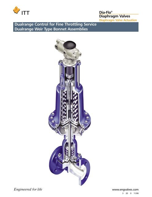
Dualrange Control for Fine Throttling Service Dualrange Weir Type ...
Dualrange Control for Fine Throttling Service Dualrange Weir Type ...
Dualrange Control for Fine Throttling Service Dualrange Weir Type ...

You also want an ePaper? Increase the reach of your titles
YUMPU automatically turns print PDFs into web optimized ePapers that Google loves.
<strong>Dualrange</strong> <strong>Control</strong> <strong>for</strong> <strong>Fine</strong> <strong>Throttling</strong> <strong>Service</strong><br />
<strong>Dualrange</strong> <strong>Weir</strong> <strong>Type</strong> Bonnet Assemblies<br />
Dia-Flo ®<br />
Diaphragm Valves<br />
Diaphragm Valve Actuation<br />
www.engvalves.com<br />
3 20 0 11/06
<strong>Dualrange</strong> <strong>Control</strong> <strong>for</strong> <strong>Fine</strong> <strong>Throttling</strong> <strong>Service</strong><br />
Principle of Operation<br />
The superior per<strong>for</strong>mance of the <strong>Dualrange</strong>® <strong>Control</strong> Valve is the<br />
result of a simple yet effective innovation in diaphragm valve<br />
design: a two-piece compressor.<br />
The two-piece compressor design not only permits greater<br />
rangeability in the valve, hence improved flow control, but provides<br />
porting which is more conducive to streamlined flow. This type<br />
of opening can handle slurries without excessive abrasion,<br />
dewatering or wiredrawing. The <strong>Dualrange</strong> should be supplied<br />
whenever precise throttling is required.<br />
How It Works<br />
During the initial movement of the valve stem, only the inner<br />
compressor moves. This permits smaller increases in flow <strong>for</strong> the<br />
same increase in stroke resulting in better modulation than<br />
conventionally designed diaphragm valves. Because the valve can<br />
now control within desired parameters more accurately, it is better<br />
able to create the desired flow conditions or pressure drop through<br />
the valve and avoid control valve hunting.<br />
When the inner compressor is open to its limit, the outer compressor<br />
begins to open. From this point on, both compressors move as<br />
a unit. When wide open, the <strong>Dualrange</strong> provides the same full flow<br />
capacities as the conventional weir type designs.<br />
The advantages gained in flow control by this design over the<br />
conventional diaphragm valve can be seen in the charts on page<br />
3-20.<br />
Because the <strong>Dualrange</strong> <strong>Control</strong> Valve must be able to position<br />
itself in an infinite range of positions from full open to full closed<br />
and hold these positions, it must be used in conjunction with a<br />
positioner. The positioner is the device that modulates the plant air<br />
to the valve operator in relation to the instrument air signal being<br />
fed by a control device.<br />
Dia-Flo ®<br />
Diaphragm Valves<br />
Diaphragm Valve Actuation<br />
<strong>Dualrange</strong> vs Conventional <strong>Weir</strong> Valve<br />
<strong>Dualrange</strong> in<br />
control<br />
position...<br />
cylindrical port<br />
yields superior<br />
control.<br />
<strong>Dualrange</strong> Conventional<br />
<strong>Fine</strong> <strong>Throttling</strong><br />
<strong>Dualrange</strong> Conventional<br />
Full Open<br />
www.engvalves.com<br />
3 21 0 11/06
<strong>Dualrange</strong> <strong>Control</strong> <strong>for</strong> <strong>Fine</strong> <strong>Throttling</strong> <strong>Service</strong><br />
Applications<br />
The <strong>Dualrange</strong> <strong>Control</strong> Valve is designed to operate at a maximum<br />
line pressure of 100 psi (689 kPa) and is recommended <strong>for</strong> use<br />
with the Dia-Flo ® weir type diaphragm <strong>for</strong> applications as follows:<br />
� Where a cost effective control valve is required on corrosive<br />
services.<br />
� Where abrasives reduce valve life on throttling applications.<br />
� Wherever positive closure and/or fine throttling are required in<br />
a control application.<br />
Valve Flow Characteristics<br />
<strong>Dualrange</strong> Valve Notes…<br />
� For use on weir type valves only<br />
� Positioners are required<br />
� Maximum line pressure is 100 psi<br />
� Available size range 1”-6”<br />
Dia-Flo ®<br />
Diaphragm Valves<br />
Diaphragm Valve Actuation<br />
� Where slurries may clog ordinary diaphragm valves when<br />
throttling.<br />
� Where valves large enough to handle normal process flows<br />
cannot throttle low enough to control small amounts of flow<br />
required during start-up operations.<br />
� Where split-ranging has been necessary to<br />
provide rangeability not available in a single<br />
diaphragm valve.<br />
www.engvalves.com<br />
3 22 0 11/06
<strong>Dualrange</strong> <strong>Control</strong> <strong>for</strong> <strong>Fine</strong> <strong>Throttling</strong> <strong>Service</strong><br />
<strong>Control</strong> Systems<br />
With the <strong>Dualrange</strong> <strong>Control</strong> Valve<br />
<strong>Dualrange</strong> <strong>Control</strong> Valves are used in a variety of throttling<br />
applications where fine control is required. Typical applications<br />
include flow control, level control, back pressure control and many<br />
others. The <strong>Dualrange</strong>, however, is merely a single component in a<br />
complex system known as the control loop. In order to properly<br />
apply the <strong>Dualrange</strong> <strong>Control</strong> Valve, it is important to understand<br />
not only how the control loop works, but also what is trying to be<br />
accomplished downstream of the valve. The following schematic<br />
shows a typical single valve control loop:<br />
Dia-Flo ®<br />
Diaphragm Valves<br />
Diaphragm Valve Actuation<br />
www.engvalves.com<br />
3 23 0 11/06
<strong>Dualrange</strong> <strong>Control</strong> <strong>for</strong> <strong>Fine</strong> <strong>Throttling</strong> <strong>Service</strong><br />
Sizing a <strong>Dualrange</strong> <strong>Control</strong> Valve<br />
Dia-Flo ® <strong>Dualrange</strong> valves are modulating control valves. As a<br />
result, precautions must be taken in sizing and selecting the valve<br />
versus an on-off valve. The following in<strong>for</strong>mation must be known:<br />
1. FLUID – Description of fluid including type of fluid, solids<br />
content, abrasive nature, etc.<br />
2. CONCENTRATION – This would include chemical concentration<br />
and solids concentration.<br />
3. SPECIFIC GRAVITY<br />
4. FLOW RATE – It is important when sizing a control valve to<br />
have the minimum, maximum, and<br />
normal flow rates.<br />
5. PRESSURE DROP – To be taken across valve, also known as<br />
delta-P or Δ P. It’s important to<br />
have minimum, maximum, and normal also.<br />
6. INSTRUMENT SIGNAL OR CONTROL SIGNAL – This would<br />
normally be a 3-15 psi control signal. Other pneumatic signals<br />
are available such as 6-30, 3-9, etc. In addition, electronic<br />
signals are available such as 4-20 ma (milliamp).<br />
Dia-Flo ®<br />
Diaphragm Valves<br />
Diaphragm Valve Actuation<br />
7. LINE SIZE - When the above in<strong>for</strong>mation is available, the<br />
proper valve size can be determined. You may use the flow<br />
<strong>for</strong>mulas that appear in the technical section of this binder.<br />
The diaphragm valve is sensitive to two conditions in a throttling<br />
situation. After you have determined valve size the following two<br />
tests must be done:<br />
1. PRESSURE DROP (Δ P) Across Valve – The internal flow path<br />
of a diaphragm valve closely approximates the design of a high<br />
recovery valve. The valve is not designed to withstand large<br />
pressure drops. To avoid cavitation, Δ P shall be limited to 25%<br />
of P1 absolute (P1a). P1a = inlet<br />
gage pressure plus 14.7.<br />
2. VELOCITY OVER THE WEIR AREA – For optimum per<strong>for</strong>mance,<br />
velocity over the weir should be limited to 15-20 fps<br />
(feet per second) <strong>for</strong> clear fluids and 8-10 fps <strong>for</strong> light slurries.<br />
See the technical section of this binder <strong>for</strong> area over the weir<br />
and velocity equation.<br />
www.engvalves.com<br />
3 24 0 11/06