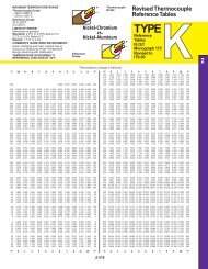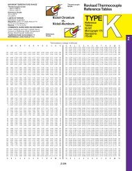
Fiber Optics Temperature Measurement by OMEGA
Fiber Optics Temperature Measurement by OMEGA
Fiber Optics Temperature Measurement by OMEGA

Create successful ePaper yourself
Turn your PDF publications into a flip-book with our unique Google optimized e-Paper software.
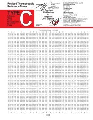
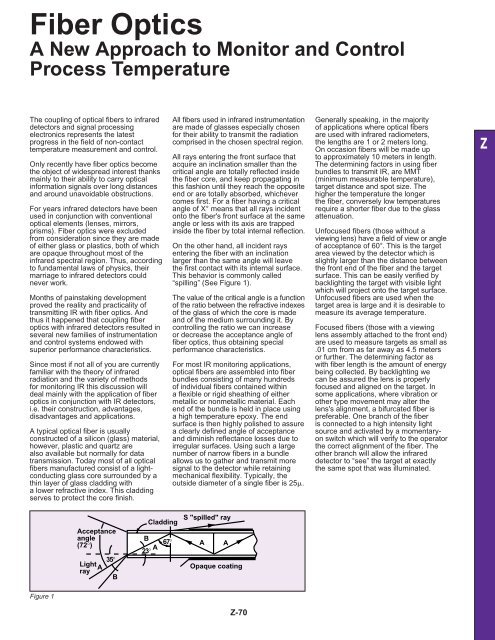
<strong>Fiber</strong> <strong>Optics</strong>A New Approach to Monitor and ControlProcess <strong>Temperature</strong>The coupling of optical fibers to infrareddetectors and signal processingelectronics represents the latestprogress in the field of non-contacttemperature measurement and control.Only recently have fiber optics becomethe object of widespread interest thanksmainly to their ability to carry opticalinformation signals over long distancesand around unavoidable obstructions.For years infrared detectors have beenused in conjunction with conventionaloptical elements (lenses, mirrors,prisms). <strong>Fiber</strong> optics were excludedfrom consideration since they are madeof either glass or plastics, both of whichare opaque throughout most of theinfrared spectral region. Thus, accordingto fundamental laws of physics, theirmarriage to infrared detectors couldnever work.Months of painstaking developmentproved the reality and practicality oftransmitting IR with fiber optics. Andthus it happened that coupling fiberoptics with infrared detectors resulted inseveral new families of instrumentationand control systems endowed withsuperior performance characteristics.Since most if not all of you are currentlyfamiliar with the theory of infraredradiation and the variety of methodsfor monitoring IR this discussion willdeal mainly with the application of fiberoptics in conjunction with IR detectors,i.e. their construction, advantages,disadvantages and applications.A typical optical fiber is usuallyconstructed of a silicon (glass) material,however, plastic and quartz arealso available but normally for datatransmission. Today most of all opticalfibers manufactured consist of a lightconductingglass core surrounded <strong>by</strong> athin layer of glass cladding witha lower refractive index. This claddingserves to protect the core finish.All fibers used in infrared instrumentationare made of glasses especially chosenfor their ability to transmit the radiationcomprised in the chosen spectral region.All rays entering the front surface thatacquire an inclination smaller than thecritical angle are totally reflected insidethe fiber core, and keep propagating inthis fashion until they reach the oppositeend or are totally absorbed, whichevercomes first. For a fiber having a criticalangle of X° means that all rays incidentonto the fiber's front surface at the sameangle or less with its axis are trappedinside the fiber <strong>by</strong> total internal reflection.On the other hand, all incident raysentering the fiber with an inclinationlarger than the same angle will leavethe first contact with its internal surface.This behavior is commonly called“spilling” (See Figure 1).The value of the critical angle is a functionof the ratio between the refractive indexesof the glass of which the core is madeand of the medium surrounding it. Bycontrolling the ratio we can increaseor decrease the acceptance angle offiber optics, thus obtaining specialperformance characteristics.For most IR monitoring applications,optical fibers are assembled into fiberbundles consisting of many hundredsof individual fibers contained withina flexible or rigid sheathing of eithermetallic or nonmetallic material. Eachend of the bundle is held in place usinga high temperature epoxy. The endsurface is then highly polished to assurea clearly defined angle of acceptanceand diminish reflectance losses due toirregular surfaces. Using such a largenumber of narrow fibers in a bundleallows us to gather and transmit moresignal to the detector while retainingmechanical flexibility. Typically, theoutside diameter of a single fiber is 25.Generally speaking, in the majorityof applications where optical fibersare used with infrared radiometers,the lengths are 1 or 2 meters long.On occasion fibers will be made upto approximately 10 meters in length.The determining factors in using fiberbundles to transmit IR, are MMT(minimum measurable temperature),target distance and spot size. Thehigher the temperature the longerthe fiber, conversely low temperaturesrequire a shorter fiber due to the glassattenuation.Unfocused fibers (those without aviewing lens) have a field of view or angleof acceptance of 60°. This is the targetarea viewed <strong>by</strong> the detector which isslightly larger than the distance betweenthe front end of the fiber and the targetsurface. This can be easily verified <strong>by</strong>backlighting the target with visible lightwhich will project onto the target surface.Unfocused fibers are used when thetarget area is large and it is desirable tomeasure its average temperature.Focused fibers (those with a viewinglens assembly attached to the front end)are used to measure targets as small as.01 cm from as far away as 4.5 metersor further. The determining factor aswith fiber length is the amount of energybeing collected. By backlighting wecan be assured the lens is properlyfocused and aligned on the target. Insome applications, where vibration orother type movement may alter thelens's alignment, a bifurcated fiber ispreferable. One branch of the fiberis connected to a high intensity lightsource and activated <strong>by</strong> a momentaryonswitch which will verify to the operatorthe correct alignment of the fiber. Theother branch will allow the infrareddetector to “see” the target at exactlythe same spot that was illuminated.ZAcceptanceangle(72°)35°LightArayBCladdingB67°A23°S "spilled" rayA AOpaque coatingFigure 1Z-70
<strong>Fiber</strong> <strong>Optics</strong> Cont'dFIBER ASSEMBLY VARIETIESThe wide selection of fibers and lensconfigurations available allows for asatisfying and endless number ofapplications.Following are some of the manycomponents that make up a fiber opticsystem and allow for such versatility.Sheathing– Single, bifurcated or trifurcated fiberoptic systems– Flexible stainless steel (standard)– Heavy duty S.S. wire braid– Heavy duty braided fiber ImperialEastman– Teflon (for use in high RF fields)– Protective tubingLenses– 1.27 cm, 1.90 cm, 2.54 cm x 8.59 cmto 27.7 cm max.– Natural - black anodized aluminum– Angular lens configurations availableReplaceable Tips– Glass or quartz, 7.62 cm, 15.24 cm &22.86 cm long– Ceramic or stainless steel jacketOptical Rods– Glass, 15.24 cm, 30.48 cm &60.96 cm long– Ceramic or stainless steel jacketSpecials– Right angle prisms, high speedscanners, angled bundle configurationsAPPLICATIONSSince virtually every manufacturedproduct – from automobiles to the safetypin – requires the application of heattreatment in some form, the use for noncontacttemperature monitoring andcontrol is virtually limitless.INDUCTION HEATINGBecause of the strong RF inductiveenergy field needed to heat the metalparts being treated, conventionalmeasuring devices are of little valuesince they will be heated directly <strong>by</strong>the induction coil.Figures 2 and 3 show typical applicationsof fiber optic systems used to monitorand control induction treatment of metalobjects either stationary in, or movingthrough induction furnaces.Precise control of the temperatureneeded for perfect heat treatment ofmetal parts is essential to producethe crystal structure that will ensuremeeting or exceeding the mechanicalcharacteristic specifications.This control function is achieved either<strong>by</strong> on/off or high speed proportionalcontrol incorporated in the fiber opticFigure 2: Monitoring steel rod continuesinduction heating.Figure 3: Controlling induction treating ofautomotive crankshafts.and Thermal Monitoring System.Using fiber optics vs. the conventionaldirect line of sight infrared detectionsystems allows placing the viewing endof the fiber optic in close proximity of thetarget. The tip of the fiber in many casesmay be positioned between the inductioncoils to view the processed material. Toeliminate the adverse effects of the RFfield a ceramic replaceable tip is utilized.In those instances where the designof the system won't allow room forthe fibers, a lens system will then beprovided to view and monitor targetsfrom a distance.The fiber and electronics normally arenot affected <strong>by</strong> induction energy fields,however, in unusual circumstanceswhen the electrical noise environmentis excessively high, a synchronousdemodulation system is specified.The sync. demod, converts the 400 HzAC signal from the detector head toDC. This conversion differs fromconventional AC to DC converters inthat it selects only the signal componentat 400 Hz and discriminates againstnoise components of other frequencies.CONTINUOUS CASTINGThese operations utilize fiber opticZ-71Figure 4: Five-channel multiplexing,signal-processing and display system.assemblies up to thirty feet in lengththat are installed between the rollersthemselves to within one or two inchesof the slab surface. A remotely locatedautomatic multiplexing chassis monitorsseveral points on a time shared basis,achieving significant savings in termsof cost and space. Due to the shieldedpath of constant transmissivity provided<strong>by</strong> the optical fibers and the short wavelength 0.8 to 1 silicon detector, the system“watches” the target through smoke,fumes, vapors and water. (See Figure 4.)Quite often in this type of applicationthe fibers are exposed to substantiallyelevated temperatures and mechanicalabuse necessitating the need for airpurging and special heavy duty protectivesheathing. The purge tube is designedto allow the air flow to exit the frontend of the fibers at a right angle thuspreventing the build up of contaminants.METAL FORGING, HOT STAMPING,PIPE BENDINGForging of metal parts includes bothrough shape as well as precision forging,which requires less material removaland waste. Pipe bending and shaping isalso included in this application. Theseoperations are carried out <strong>by</strong> heatingthe parts to be worked upon to theoptimum temperature with any ofthe several means available (ovens,flame, induction field, etc.) If the parttemperature is below the optimum,cracks and internal tensions will develop,while if it is above the optimum, droopingwill take place. The precise temperaturecontrol afforded <strong>by</strong> the use of infraredfiber optic controllers will:– Avoid the formation of defectiveparts (from cracks or drooping), thuseliminating rejects and waste due tothese defects;– Save thermal energy <strong>by</strong> ensuring thatno heat is wasted <strong>by</strong> heating the parts
ZFigure 5beyond the optimum level;– Speed up production <strong>by</strong> allowing afaster rate of heating the parts withoutdanger of temperature overshoot.METAL DIE CASTINGThe die temperature is of criticalimportance in die casting of metals.Thermal cycling of aluminum products,with reference to die temperature hasbeen successfully implemented with thehelp of optical fibers. Figure 5 showsschematically and in detail how the frontend of the fiber is inserted through themold frame and held in a corner of therunner plate, in contact with the aluminumflowing through it.The major advantages offered <strong>by</strong> thissolution are:– Substantial savings of thermal energy,<strong>by</strong> eliminating overheating anddrastically reducing production rejects.– Increased production due to thespeedup of the casting cycle. Theoperation is automatically controlled<strong>by</strong> the temperature of the castingmaterial and not solely <strong>by</strong> time,resulting in faster operation.– Improvement in the quality of thecasting due to the control of theprocess as a function of temperature,results in simpler operation andautomatic compensation for a colddie start-up or interrupted cycles.Direct indication of the die and furnacepot temperature of the metal. Lowlevel and blocked water lines areeasily indicated several shots beforethe casting can display conditionsvisibly.CONTROL OFMETAL-WORKING LASERLasers, generally high-power CO 2 lasers,are used for welding, surface treating andfinishing metals of various types. Theconventional approach is to periodicallysample the beam to keep its power atthe desired level. This approach, however,cannot automatically take into accountFigure 6the emissivity variations of the targetsurface. These variations, in turn, affectthe amount of laser power absorbed <strong>by</strong>the target, and consequently the target'stemperature, which is of paramountimportance for good operatingperformance.This difficulty is overcome <strong>by</strong> the use ofan emissivity-independent infrared fiberFigure 7LensAssembly150Cutting Oxygen°Z-72optics system (EITM) aimed at the spotof laser beam impact. (See Figure 6.)The infrared system is made blind tothe laser wavelength, and in this way itmeasures precisely the target temperatureat the same spot and, via a feedbackloop, it controls the laser power toensure that the operation is carried outat the optimum temperature.Among the advantages offered <strong>by</strong> thefiber optics infrared approach are thefollowing:Preheating GasCutting NozzleCutting DirectionPre-heating FlameCutting Oxygen JetReactionZoneBase Metal
<strong>Fiber</strong> <strong>Optics</strong> Cont'd– Non-contact temperaturemeasurement in real time.– <strong>Fiber</strong> optics allow easy access to viewthe laser heating area because of theirrelatively small size.– EITM compensates for variations inemissivity as the part is being heated.– EITM response can be matched to theresponse speed of the laser.Additional applications of interest:FLAME CUTTINGAutomated flame cutting involves eitherpattern tracing or computer control torepetitively cut steel plates into a varietyof shapes. (See Figure 7.)During start-up, a natural gas orpropane flame heats the metal plateuntil a “puddle” of molten metal isdetected <strong>by</strong> the operator; on multipleheat cutters the time may vary betweentorches. The puddle having beenformed, oxygen is injected into the gasstream and blows the molten metalthrough the plate at which time thecutting cycle begins.If the oxygen is injected prematurelya defective cut is made leaving anobjectionable rough and wide pitlikedepression in the plate.Figure 8Flame HeadsFlameLensAssemblyQuenchSubstantial savings are realized <strong>by</strong>eliminating a previous costly process ofdestructive testing.COKE GUIDE PYROMETERBy monitoring both level andtemperature, the Coke Guide Pyrometerassures the optimum efficiency in themanufacture of coke. The multiplexingof several detectors on a vertical planeallows the operator to measure bothheight and temperature of the coke inthe processing oven.When desired parameters are met, acontroller signal activates the pusherto dump the processed coke into anawaiting transfer car, thus assuringa quality product and energyconservation.The above are but a few of the manyand varied uses of fiber optics. Therange and applications for thesesystems is only limited <strong>by</strong> one'simagination. The technology isexpanding exponentially. <strong>Fiber</strong> opticsare no longer viewed with doubts andmisgivings. Like IC's, chips, bubblememories, RAM's, ROM's and PROM's,they are here to stay, they are thefuture.By positioning a fiber optic bundlewith lens assembly to look throughthe “clean” flame at the plate surface,the temperature is monitored andcontrolled to maintain the necessarytemperature. By multiplexing and usinghi-lo logic with relays tied in series, theoxygen is not turned on until all setpointsand associated relays are closed, insuringhigh quality cuts.FLAME HARDENING OFSTEEL WHEELSHardening the surfaces of steel wheelsused on heavy construction equipmentsuch as drive & idler wheels forbulldozers, backhoes, and other tracktype equipment is presently beingaccomplished <strong>by</strong> flame hardening.A flame head is positioned on eitherside of the wheel (Figure 8). As thewheel is rotated the flame impinges onthe surface elevating the temperature toapproximately 976°C. Within closeproximity to the flame the surface israpidly quenched with cooling water(Figure 9).Because of the variations in the wheels,both in roundness and lateraldistortions, if the flame head were fixedthe hardening process would not beuniform throughout the critical areas.Figure 9By optically looking through the “clean”natural gas flame at the optimum pointon the wheel, Figure 10, the variationsin the temperature determined <strong>by</strong> theThermal Monitor provide a proportionalsignal which is fed to a pneumatictransducer which pneumo/mechanicallymoves the head to the correct position.Figure 10Z-73Reproduced with permission ofVanzetti Instruments.OptimumMeasuringPoint