Cathodic Protection of Aluminium Hulls in Sea Water - MGDUFF
Cathodic Protection of Aluminium Hulls in Sea Water - MGDUFF
Cathodic Protection of Aluminium Hulls in Sea Water - MGDUFF

You also want an ePaper? Increase the reach of your titles
YUMPU automatically turns print PDFs into web optimized ePapers that Google loves.
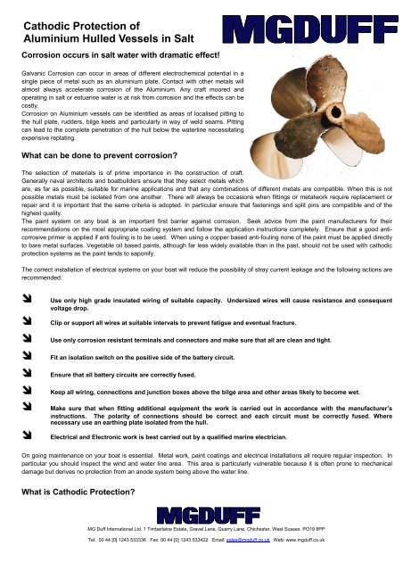
<strong>Cathodic</strong> <strong>Protection</strong> <strong>of</strong><strong>Alum<strong>in</strong>ium</strong> Hulled Vessels <strong>in</strong> SaltCorrosion occurs <strong>in</strong> salt water with dramatic effect!Galvanic Corrosion can occur <strong>in</strong> areas <strong>of</strong> different electrochemical potential <strong>in</strong> as<strong>in</strong>gle piece <strong>of</strong> metal such as an alum<strong>in</strong>ium plate. Contact with other metals willalmost always accelerate corrosion <strong>of</strong> the <strong>Alum<strong>in</strong>ium</strong>. Any craft moored andoperat<strong>in</strong>g <strong>in</strong> salt or estuar<strong>in</strong>e water is at risk from corrosion and the effects can becostly.Corrosion on <strong>Alum<strong>in</strong>ium</strong> vessels can be identified as areas <strong>of</strong> localised pitt<strong>in</strong>g tothe hull plate, rudders, bilge keels and particularly <strong>in</strong> way <strong>of</strong> weld seams. Pitt<strong>in</strong>gcan lead to the complete penetration <strong>of</strong> the hull below the waterl<strong>in</strong>e necessitat<strong>in</strong>gexpensive replat<strong>in</strong>g.What can be done to prevent corrosion?The selection <strong>of</strong> materials is <strong>of</strong> prime importance <strong>in</strong> the construction <strong>of</strong> craft.Generally naval architects and boatbuilders ensure that they select metals whichare, as far as possible, suitable for mar<strong>in</strong>e applications and that any comb<strong>in</strong>ations <strong>of</strong> different metals are compatible. When this is notpossible metals must be isolated from one another. There will always be occasions when fitt<strong>in</strong>gs or metalwork require replacement orrepair and it is important that the same criteria is adopted. In particular ensure that fasten<strong>in</strong>gs and split p<strong>in</strong>s are compatible and <strong>of</strong> thehighest quality.The pa<strong>in</strong>t system on any boat is an important first barrier aga<strong>in</strong>st corrosion. Seek advice from the pa<strong>in</strong>t manufacturers for theirrecommendations on the most appropriate coat<strong>in</strong>g system and follow the application <strong>in</strong>structions completely. Ensure that a good anticorrosiveprimer is applied if anti foul<strong>in</strong>g is to be used. When us<strong>in</strong>g a copper based anti-foul<strong>in</strong>g none <strong>of</strong> the pa<strong>in</strong>t must be applied directlyto bare metal surfaces. Vegetable oil based pa<strong>in</strong>ts, although far less widely available than <strong>in</strong> the past, should not be used with cathodicprotection systems as the pa<strong>in</strong>t tends to saponify.The correct <strong>in</strong>stallation <strong>of</strong> electrical systems on your boat will reduce the possibility <strong>of</strong> stray current leakage and the follow<strong>in</strong>g actions arerecommended:Use only high grade <strong>in</strong>sulated wir<strong>in</strong>g <strong>of</strong> suitable capacity. Undersized wires will cause resistance and consequentvoltage drop.Clip or support all wires at suitable <strong>in</strong>tervals to prevent fatigue and eventual fracture.Use only corrosion resistant term<strong>in</strong>als and connectors and make sure that all are clean and tight.Fit an isolation switch on the positive side <strong>of</strong> the battery circuit.Ensure that all battery circuits are correctly fused.Keep all wir<strong>in</strong>g, connections and junction boxes above the bilge area and other areas likely to become wet.Make sure that when fitt<strong>in</strong>g additional equipment the work is carried out <strong>in</strong> accordance with the manufacturer’s<strong>in</strong>structions. The polarity <strong>of</strong> connections should be correct and each circuit must be correctly fused. Wherenecessary use an earth<strong>in</strong>g plate isolated from the hull.Electrical and Electronic work is best carried out by a qualified mar<strong>in</strong>e electrician.On go<strong>in</strong>g ma<strong>in</strong>tenance on your boat is essential. Metal work, pa<strong>in</strong>t coat<strong>in</strong>gs and electrical <strong>in</strong>stallations all require regular <strong>in</strong>spection. Inparticular you should <strong>in</strong>spect the w<strong>in</strong>d and water l<strong>in</strong>e area. This area is particularly vulnerable because it is <strong>of</strong>ten prone to mechanicaldamage but derives no protection from an anode system be<strong>in</strong>g above the water l<strong>in</strong>e.What is <strong>Cathodic</strong> <strong>Protection</strong>?MG Duff International Ltd. 1 Timberla<strong>in</strong>e Estate, Gravel Lane, Quarry Lane, Chichester, West Sussex. PO19 8PPTel: 00 44 [0] 1243 533336 Fax: 00 44 [0] 1243 533422 Email: sales@mgduff.co.uk Web: www.mgduff.co.uk
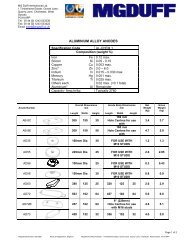
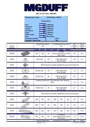
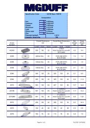
CATHODIC PROTECTION IS AN ELECTROCHEMICAL PROCESS WHICH HALTS THE NATURAL REACTION (CORROSION) OFMETALS IN A PARTICULAR ENVIRONMENT BY SUPERIMPOSING AN ELECTROCHEMICAL CELL MORE POWERFUL THANTHE CORROSION CELL.Sacrificial Anodes are fitted or bonded to the metal to be protected, this results <strong>in</strong> an electrical potential difference and the metalbecomes cathodic caus<strong>in</strong>g the sacrificial anode to waste <strong>in</strong>stead. In a correctly <strong>in</strong>stalled <strong>MGDUFF</strong> <strong>Cathodic</strong> <strong>Protection</strong> Systemcorrosion only occurs to the sacrificial anode which is replaceable. The number and size <strong>of</strong> anodes is determ<strong>in</strong>ed by the type <strong>of</strong>material and the surface area be<strong>in</strong>g protected.Several factors determ<strong>in</strong>e the type <strong>of</strong> cathodic protection system fitted. Firstly the environment <strong>in</strong> which the vessel is operat<strong>in</strong>g,secondly the size and type <strong>of</strong> construction and f<strong>in</strong>ally the length <strong>of</strong> time that the vessel is likely to be afloat before the next ma<strong>in</strong>tenanceslipp<strong>in</strong>g.<strong>MGDUFF</strong> recommend the use <strong>of</strong> Z<strong>in</strong>c anodes for vessels permanently kept on a salt water berth.Anode SelectionThe number, type and position<strong>in</strong>g <strong>of</strong> z<strong>in</strong>c anodes for full underwater hull protection is dependent upon the follow<strong>in</strong>g factors:-a) Area <strong>of</strong> immersed plat<strong>in</strong>g and structure.b) Efficiency <strong>of</strong> underwater pa<strong>in</strong>t coat<strong>in</strong>gs.c) Anode life required.d) Type and area <strong>of</strong> other underwater metalwork.e) Type <strong>of</strong> anode considered most suitable.The follow<strong>in</strong>g anode selection table, assumes conventionally designed vessels - whether pleasure or work<strong>in</strong>g craft, hav<strong>in</strong>g goodunderwater pa<strong>in</strong>t coat<strong>in</strong>gs with m<strong>in</strong>imal pa<strong>in</strong>t loss (less than 10% over 24 months).To select the correct type and size <strong>of</strong> anode, calculate the wetted surface area (see below) and enter the table with wetted surfacearea.Wetted Surface Area CalculationsUs<strong>in</strong>g the ma<strong>in</strong> dimensions <strong>of</strong> the vessel <strong>in</strong> metres, i.e. length (waterl<strong>in</strong>e), breadth and draft (mean loaded), calculate area by thefollow<strong>in</strong>g formula: L W L x (Breadth + Draft). The result<strong>in</strong>g area applies to tugs, trawlers ferries, motor cruisers, launches and fullbodied sail<strong>in</strong>g craft.ANODE SELECTION TABLEfor craft operat<strong>in</strong>g <strong>in</strong> salt waterWetted Surface Area ZD42 Z<strong>in</strong>c StripAnodesZD55 RecessedZ<strong>in</strong>c AnodesZD72BM Z<strong>in</strong>cHull AnodesAssum<strong>in</strong>g a goodpa<strong>in</strong>t system12 monthanode life24 monthanode life24 monthanode life(0 - 15.0m2) 2 x ZD42/36" 2 x ZD55 2 x ZD72BM(15.1 - 30.0m2) 2 x ZD42/54" 2 x ZD55 2 x ZD72BM(30.1 - 45.0m2) 4 x ZD42/36" 4 x ZD55 4 x ZD72BM(45.1 - 60.0m2) 4 x ZD42/54" 4 x ZD55 4 x ZD72BM(60.1 - 85.0m2) 6 x ZD42/54" 6 x ZD55 6 x ZD72BM(85.1 - 110.0m2) 6 x ZD42/72" 6 x ZD55 6 x ZD72BMABOVE 110.0M2CONTACT <strong>MGDUFF</strong> FOR SPECIFIC ADVICE
Anode Position<strong>in</strong>g1) Position anodes around underwater hull as shown Below. Positions may be adapted slightly to suit <strong>in</strong>dividualvessels.2) Prepare and pa<strong>in</strong>t the hull <strong>in</strong> accordance with a reputable pa<strong>in</strong>t manufacturers specification before anodes are fixed.3) Fit anodes us<strong>in</strong>g galvanised mild steel set bolts with fan disc washer mak<strong>in</strong>g sure that the anodes are pulled up tightaga<strong>in</strong>st the hull.4) No pa<strong>in</strong>t must be allowed to fall on the surface <strong>of</strong> the anode itself at any time.Ma<strong>in</strong>tenanceTo ensure correct level <strong>of</strong> protection anodes should be replaced when 80% consumed or if it isanticipated that they will be more than 80% consumed at the next scheduled dock<strong>in</strong>g.Two Anode SystemFour Anode SystemSix Anode SystemThe z<strong>in</strong>c anodes described <strong>in</strong> this leaflet are those selected from our anode range as suitablefor general small and <strong>in</strong>termediate size craft <strong>of</strong> various types.The methods <strong>of</strong> fitt<strong>in</strong>g the various anodes are detailed below.Type ZD42 strip anodes:This is a low pr<strong>of</strong>ile z<strong>in</strong>c anode with a non reactive alum<strong>in</strong>ium <strong>in</strong>sert, ideally suited forfitt<strong>in</strong>g to high speed alum<strong>in</strong>ium hulled vessels. The anode is not recessed but prom<strong>in</strong>enton hull surface and can be attached after construction.Each anode requires 3 or more fix<strong>in</strong>g positions:-44mmZD42/36” and ZD42/54”ZD42/72”-3 fix<strong>in</strong>g positions-5 fix<strong>in</strong>g positions (7 on fast craft).The ZD42 anode is supplied <strong>in</strong> 6ft (1830mm) lengths and may be cut to length. Itcan be supplied un-drilled or drilled and counter bored to standard centres,Fix<strong>in</strong>g holes are drilled to suit 10mm studs and it is imperative that the fix<strong>in</strong>g holeis counter bored down to the alum<strong>in</strong>ium core.13mm26mm11mm7mmThis shows a typical <strong>in</strong>stallation (suitable for attachment afterconstruction).<strong>Alum<strong>in</strong>ium</strong>Hull<strong>Alum<strong>in</strong>ium</strong> Bossdrilled and tapped<strong>in</strong> way <strong>of</strong> eachfix<strong>in</strong>g hole.<strong>Alum<strong>in</strong>ium</strong>Hull<strong>Alum<strong>in</strong>ium</strong>Back<strong>in</strong>g Pad10mm Fix<strong>in</strong>g Boltand serrated washerZD42Z<strong>in</strong>cAnodeZD42Z<strong>in</strong>cAnode10mm Fix<strong>in</strong>gStud andserrated washerThis shows a typical <strong>in</strong>stallation(show<strong>in</strong>g fitt<strong>in</strong>g arrangement for new build<strong>in</strong>gs.)
Hull mounted ZD55 Recessed Disc AnodesThis 9” (225mm) diameter anode is generally utilised for flushmount<strong>in</strong>g when m<strong>in</strong>imum drag is required and is therefore normally<strong>in</strong>corporated on new construction where the circular recess can bearranged more easily<strong>Alum<strong>in</strong>ium</strong>HullFabricatedRecessZD55 Z<strong>in</strong>cAnode<strong>Alum<strong>in</strong>ium</strong> Bossdrilled and tapped<strong>in</strong> way <strong>of</strong> fix<strong>in</strong>g hole10mm Fix<strong>in</strong>g Screwand serrated washerFlexible Masticaround outer edgeand back face<strong>of</strong> the anode<strong>Alum<strong>in</strong>ium</strong>HullRubberisedBack<strong>in</strong>g SheetZD72BMZ<strong>in</strong>cAnode<strong>Alum<strong>in</strong>ium</strong>Washer10mm Fix<strong>in</strong>gStud andserrated washer<strong>Alum<strong>in</strong>ium</strong> Bossdrilled and tapped<strong>in</strong> way <strong>of</strong> eachFix<strong>in</strong>g hole.Trim Tabs and RuddersType ZD72B(M) Z<strong>in</strong>c Hull Anode:This low pr<strong>of</strong>ile cast anode is suitable for lower speedcraft,wheret h eTrim Tabs and Rudders will require additional anodesand we recommend that a ZD56 button anode is fittedon to each side <strong>of</strong> the rudders and to the top side <strong>of</strong>each trim tab. If the surface area <strong>of</strong> each side isgreater than 1m 2 the size <strong>of</strong> the anode must be<strong>in</strong>creased to a ZD58.Shaft Bond<strong>in</strong>gTo provide the best protection to the stern gear <strong>of</strong> your boat the shaft should be fitted with an <strong>MGDUFF</strong> ElectroElim<strong>in</strong>ator Brush.The MGDuff Electro-Elim<strong>in</strong>ators <strong>of</strong>fer the most effective shaft bond<strong>in</strong>g solution. Runn<strong>in</strong>g directly onto thepropeller shaft the electro elim<strong>in</strong>ator puts the anode <strong>in</strong> constant low resistance contact with the propeller shaft. Thecopper graphite brushes will give at least 2000 runn<strong>in</strong>g hours under normal conditions. The electro elim<strong>in</strong>ators willalso remove the irritat<strong>in</strong>g <strong>in</strong>terference to electronic equipment caused by the rotat<strong>in</strong>g shaft.Electro Elim<strong>in</strong>ator Number 2for 2” - 8” diameter shafts(A support bracket must befabricated to suit the <strong>in</strong>stallation<strong>of</strong> the unit, not supplied)Electro Elim<strong>in</strong>ator Number 1for up to 2” diameter shafts(<strong>in</strong>cludes supportbracket as shown)