Download the Complete Catalog in One PDF - Ramset
Download the Complete Catalog in One PDF - Ramset
Download the Complete Catalog in One PDF - Ramset

Create successful ePaper yourself
Turn your PDF publications into a flip-book with our unique Google optimized e-Paper software.
Powder Tra<strong>in</strong><strong>in</strong>g Certification. . . . . . . . . . . . . . . . . . . . . . . . . . . . . . .4Buy American Act ....................................5Into To Gas Technology ....................................6Suggested Specifications ..................................7Fasteners – How They Work ................................8LEED Credits ...................................10Toubleshoot<strong>in</strong>g ...................................11Tool Selection Guide ...................................12Powder Fastener & Load Selection Chart ....................14Gas Fasten<strong>in</strong>g SystemsT3MAG ................................... 16TrakFast ................................... 17T3SS ................................... 18GypFastG2 ................................... 19Powder Fasten<strong>in</strong>g SystemsR25 ................................... 20XT540 ................................... 21SA270 ................................... 22Cobra ................................... 22Viper ................................... 23D45A ................................... 24D60 ................................... 24721 ................................... 25MasterShot ................................... 25T3Cup ................................... 26Extension Poles ................................. 27Tool Accessories (Batteries, Fuel Cells, Chargers, etc). .... 28FastenersGas Tool Fasteners (T3MAG, TrakFast)................. 29GypFast Tool Fasteners. ........................... 31Gas Tool Fasteners (T3ss).......................... 32Powder Fasteners. ............................... 34Powder Loads ...................................38Performance/Submittal ..................................39J Master Tool ...................................49XBA / CB CBD ...................................50Conduit / Cable Support ..................................51Strut Clamps ...................................52Beam/Purl<strong>in</strong> ...................................53Metal Stud Support ...................................55Rod Hangers ...................................57Acoustical ...................................57Harware Accessories ...................................57Low-Voltage ...................................58Part Number Reference ..................................59WoodSAMMYS for Wood. .............................. 62Sammy Swivelhead for Wood....................... 62Sidew<strong>in</strong>ders for Wood............................. 63SteelSAMMYS for Steel ............................... 64Sammy Swivelhead for Steel. ...................... 64Sidew<strong>in</strong>ders for Steel. ............................ 65SAMMY XPress.................................. 65SAMMT XPress It Installation Tool ................... 65ConcreteSAMMYS for Concrete ............................ 66Sammy Swivelhead for Concrete. ................... 66Swivelhead for Concrete........................... 66Concrete / Wood Installation Kit ..................... 67Approvals ...................................68CONCRETE ANCHORING SYSTEMSElectrical Contractor Applications ..........................70Mechanical Contractor Applications ........................71Trubolt Wedge Anchors ..................................72LDT Anchors ...................................80Multi-Set II Drop In Anchors ..............................86Dynabolt Sleeve Anchors .................................91Stud Anchors ...................................95Redi-Drive Anchors ...................................97Tapcon ..................................101EZ Ancor ..................................104Poly-Set Anchors ..................................1053
POWDER TRAININGAND CERTIFICATION<strong>Ramset</strong> has designed and eng<strong>in</strong>eered <strong>the</strong> right powderactuated tool for your applications. To ensure you use apowder actuated tool correctly, please take <strong>the</strong> time toreview <strong>the</strong> Operator's Safety and Operat<strong>in</strong>g InstructionManual packaged with each tool. These manuals are alsoavailable for download on <strong>the</strong> <strong>Ramset</strong> website.To assure safety on <strong>the</strong> jobsite, OSHA and ANSI requirethat all powder actuated tool users become tra<strong>in</strong>ed andcertified for <strong>the</strong> particular tool be<strong>in</strong>g used. <strong>One</strong> way<strong>Ramset</strong> enables you to receive this tra<strong>in</strong><strong>in</strong>g is throughour website tra<strong>in</strong><strong>in</strong>g program. This <strong>in</strong>novative approachto education comb<strong>in</strong>es <strong>in</strong>teractive web-based tra<strong>in</strong><strong>in</strong>gtechniques and onl<strong>in</strong>e test<strong>in</strong>g with immediate feedback toprovide you a rich learn<strong>in</strong>g environment.The course consists of approximately 30 pages of usage,safety and troubleshoot<strong>in</strong>g material.Upon completion of this brief course you will have <strong>the</strong>opportunity to take an onl<strong>in</strong>e exam. Instructions for tak<strong>in</strong>g<strong>the</strong>se exams are provided at <strong>the</strong> end of <strong>the</strong> course.With successful completion of <strong>the</strong> exam, you have <strong>the</strong>opportunity to pr<strong>in</strong>t a certification card.As an <strong>in</strong>dustry leader <strong>in</strong> powder actuated fasten<strong>in</strong>gsystems. <strong>Ramset</strong> cont<strong>in</strong>ues to provide <strong>the</strong> most effectiveand comprehensive <strong>in</strong>structor and operator tra<strong>in</strong><strong>in</strong>gprograms available.Visit www.ramset.comwww.ramset.com4
Dedicated to American Made ProductsThe American Recovery and Re<strong>in</strong>vestment Act of 2009 requires that all constructionmaterials for federal, state and local stimulus projects must be manufactured <strong>in</strong> <strong>the</strong>United States.<strong>Ramset</strong> is unique <strong>in</strong> <strong>the</strong> world of construction tools, fasteners and sealant manufactur<strong>in</strong>g.Overall, 98% of <strong>Ramset</strong> fasteners and accessories are made <strong>in</strong> <strong>the</strong> USA.Unlike our competitors you know you are buy<strong>in</strong>g American made products and support<strong>in</strong>g<strong>the</strong> American economy and workers when you buy <strong>Ramset</strong>. <strong>Ramset</strong>’s parent company,Ill<strong>in</strong>ois Tool Works (NYSE: ITW) employees more than 25,000 Americans.Manufacturer Tools Fasteners<strong>Ramset</strong> Tools:TrakFast Glendale Heights, IL Paris, KYGypFast Glendale Heights, IL Paris, KYT3SS Glendale Heights, IL Paris, KYT3Mag Glendale Heights, IL Paris, KYD45A Glendale Heights, IL Paris, KYBUY AMERICAN ACTSEC. 1605—Use of American iron,SEC. 1605steel, and manufactured goods.(3) <strong>in</strong>clusion of iron, steel, and(a) None of <strong>the</strong> funds appropriated manufactured goods produced <strong>in</strong>or o<strong>the</strong>rwise made available by <strong>the</strong> United States will <strong>in</strong>crease <strong>the</strong>this Act may be used for a project cost of <strong>the</strong> overall project by morefor <strong>the</strong> construction, alteration, than 25 percent.ma<strong>in</strong>tenance, or repair of a public(c) If <strong>the</strong> head of a Federal departmentor agency determ<strong>in</strong>es that itbuild<strong>in</strong>g or public work unless allof <strong>the</strong> iron, steel, and manufacturedgoods used <strong>in</strong> <strong>the</strong> project areis necessary to waive <strong>the</strong> applicationof subsection (a) based on aproduced <strong>in</strong> <strong>the</strong> United States.f<strong>in</strong>d<strong>in</strong>g under subsection (b), <strong>the</strong>(b) Subsection (a) shall not apply head of <strong>the</strong> department or agency<strong>in</strong> any case or category of cases shall publish <strong>in</strong> <strong>the</strong> Federal Registera detailed written justification<strong>in</strong> which <strong>the</strong> head of <strong>the</strong> Federaldepartment or agency <strong>in</strong>volved as to why <strong>the</strong> provision is be<strong>in</strong>gf<strong>in</strong>ds that—waived.(1) apply<strong>in</strong>g subsection (a) would (d) This section shall be applied <strong>in</strong>be <strong>in</strong>consistent with <strong>the</strong> public a manner consistent with United<strong>in</strong>terest;States obligations under <strong>in</strong>ternationalagreements.(2) iron, steel, and <strong>the</strong> relevantmanufactured goods are notproduced <strong>in</strong> <strong>the</strong> United States <strong>in</strong>sufficient and reasonably availablequantities and of a satisfactoryquality; or*Excerpted from HR 1, “American Recoveryand Re<strong>in</strong>vestment Act of 2009",Division A, Title XVI, Section 1605<strong>Ramset</strong> Manufactur<strong>in</strong>g:Powder Loads Manufactur<strong>in</strong>gGas Fuel Cells ProductionSealant Manufactur<strong>in</strong>gSpr<strong>in</strong>g Steel Manufactur<strong>in</strong>gWedge Anchors and LDT Anchors Manufactur<strong>in</strong>gTapcon Manufactur<strong>in</strong>gEZ Anchor Manufactur<strong>in</strong>gOxford, MSPontotoc, MSRockland, MAAddison, ILMichigan City, INItasca, ILElk Grove Village, IL10/12The follow<strong>in</strong>g is a sampl<strong>in</strong>g of government projects that haveutilized <strong>the</strong> Buy American Act us<strong>in</strong>g <strong>Ramset</strong> products:• Aberdeen Prov<strong>in</strong>g Grounds Project C4 (9 build<strong>in</strong>gs)• Fort Belvoir Hospital (6 build<strong>in</strong>gs)• Fort Bragg• Fort Detrick Department of Army Vacancies Serviced• Fort Meade (6 build<strong>in</strong>gs)• National Maritime Intelligent Center• Norfolk Naval Basewww.ramset.com5
<strong>in</strong>tro to gas technologyITW saw a challenge: how to create a portable tool that delivered<strong>the</strong> power of pneumatic tools without <strong>the</strong> hoses and compressors. In1991, ITW Paslode conquered <strong>the</strong> challenge with <strong>the</strong> revolution of gaspoweredtechnology. The cordless Impulse F<strong>in</strong>ish Nailer delivered <strong>the</strong>power of pneumatic tools without clutter<strong>in</strong>g job sites.With <strong>the</strong> thought of Driv<strong>in</strong>g Jobsite Speed while creat<strong>in</strong>g a safer workenvironment, ITW <strong>Ramset</strong> built upon <strong>the</strong> Paslode technology and <strong>in</strong>1992 <strong>in</strong>troduced <strong>the</strong> TrakFast to <strong>the</strong> drywall trade. It forever changed<strong>the</strong> way <strong>the</strong> world worked. In 2003, ITW <strong>Ramset</strong> followed up on <strong>the</strong>success of <strong>the</strong> TrakFast with <strong>the</strong> T3SS which is sett<strong>in</strong>g <strong>the</strong> standardfor electrical and mechanical contractors.Gas significantly lowers cost-<strong>in</strong>-place, reduces stress on <strong>the</strong> employee,and it's much quieter to use than drill<strong>in</strong>g or powder actuated tools(PATs), so you can work <strong>in</strong> occupied build<strong>in</strong>gs. There are times whenyou need <strong>the</strong> power and accuracy of our PATs—like <strong>the</strong> speed of ourD45A disc tool, or <strong>the</strong> work horse, nearly ma<strong>in</strong>tenance-free 721 s<strong>in</strong>gleshot PAT. But constant use of <strong>the</strong>se tools can be noisy and overly jarr<strong>in</strong>gon <strong>the</strong> body.• No Licens<strong>in</strong>g Required• Fast and Easy to Use• Quiet—No Recoil• No Cords or Hoses• Long Fuel Cell & Battery LifeDrywall Electrical MechanicalWhen <strong>the</strong> conditions are right, gas is <strong>the</strong> right choice.Problem:“My guys work on block all day long—from electricalboxes to furr<strong>in</strong>g. I've tried powder tools and <strong>the</strong>yblow holes <strong>in</strong> block. What makes <strong>the</strong> <strong>Ramset</strong>technology different?"Solution:<strong>Ramset</strong> technology has patentedoverdrive technology built <strong>in</strong> toevery gas-powered tool. The tool works under<strong>the</strong> same pr<strong>in</strong>cipal as a combustion eng<strong>in</strong>e. Alittle gas, a little spark and a powerful shot,without <strong>the</strong> recoil associated with powder.The <strong>in</strong>dustry transitions to gas technologyProblem:“I don’t want to have to re-license my guys towork with gas technology"Solution:S<strong>in</strong>ce <strong>the</strong>re are no loads, <strong>the</strong>re's no licens<strong>in</strong>g needed.In fact, Union Tra<strong>in</strong>ers have begun <strong>in</strong>clud<strong>in</strong>g <strong>the</strong> <strong>Ramset</strong>Gas Tools <strong>in</strong> tra<strong>in</strong><strong>in</strong>g classes, and students can't believehow easy <strong>the</strong> tools are to work with.In addition, <strong>the</strong> gas powered tools are totallyportable and can be used for almost all yourjobs—without <strong>the</strong> worry of hav<strong>in</strong>g unspent loadson your jobsite.The Inside StorySPARK PLUGSteelPowderAlwaysThe patented <strong>Ramset</strong> technology deliversprecisely balanced power elim<strong>in</strong>at<strong>in</strong>g <strong>the</strong>damage caused by overdrive <strong>in</strong> PATs.FUEL PORTHigh PSI concreteMedium PSI concreteLow PSI concretePan deckGrout filled blocksubstrate materialGas PreferredGasdaily shot frequencyLow Medium High Very highHow it works: As <strong>the</strong> nosepiece is depressed,a rechargeable battery turns on <strong>the</strong> fanmotor. In less than a second: a preciseamount of fuel is <strong>in</strong>jected <strong>in</strong>to <strong>the</strong> combustionchamber. When <strong>the</strong> trigger is pulled, aspark creates an explosion that drives <strong>the</strong>piston <strong>in</strong>to <strong>the</strong> fastener, and <strong>the</strong> fastener<strong>in</strong> <strong>the</strong> work surface. The action creates avacuum that pulls <strong>the</strong> piston back to <strong>the</strong>start position.In fact <strong>the</strong> technology is so precise it won'tblow through a pop can.FAN MOTORCOMBUSTIONCHAMBERPISTONASSEMBLYCYLINDER6 www.ramset.com
SUGGESTED SPECIFICATIONS<strong>Ramset</strong> provides <strong>the</strong> architect andeng<strong>in</strong>eer <strong>the</strong> follow<strong>in</strong>g suggestedlanguage and helpful <strong>in</strong>formation for<strong>the</strong> purpose of fasten<strong>in</strong>g specifications.Plywood to Metal Fram<strong>in</strong>gor TrussPart Number PLY138Fasteners used shall have a 0.100nom<strong>in</strong>al shank diameter with helical knurland a length of 1-3/8-<strong>in</strong>ches.Track or Clip to Steel BeamPart Number 1503K (pg.35)Fasteners used shall have a 0.300head with a 0.145 knurled shankdiameter and a length of 1/2-<strong>in</strong>ches.Part Number TE12 (pg.37)Fasteners used shall have a 0.320 headwith a 0.157 knurled shank diameterand a length of .545 <strong>in</strong>ches.Part Number TE100 (pg.37)Fasteners shall be designated “TrueEmbedment” type with a 0.320 headwith a 0.157 shank and length of 1.0625provid<strong>in</strong>g m<strong>in</strong>imum of 1” of embedment<strong>in</strong> up to 14ga track. Fastener shall have<strong>the</strong> embedment depth of 1” stampedon head.Interior Partition Track toConcretePart Number T3034B (pg.29)Fasteners shall be designated T3 Typewith a 0.125 nom<strong>in</strong>al shank diameterand a length of 3/4 <strong>in</strong>ch.Exterior Sheath<strong>in</strong>gto Metal StudPart Number GF112 (pg.31)Fasteners designated“GYPFAST" and have ahelical knurled shankwith a 1-1/2" LengthExterior PerimeterTrack to ConcretePart Number 1510SD (pg.35)Fasteners used shall havea 0.145 nom<strong>in</strong>al shankdiameter and a lengthof 1-1/4 <strong>in</strong>ches. Thefastener shall have apre-assembled 7/8-<strong>in</strong>chwasher.Part Number SP114 (pg.36)Fasteners used shall bedesignated PowerPo<strong>in</strong>ttype with a 0.150/.180 steppedshank and a length of 1-1/4<strong>in</strong>ches.For assistance with specifications and/or substitutions, contact Technical Service at 800-726-7386.www.ramset.com7
Fasteners – how <strong>the</strong>y workSelect<strong>in</strong>g <strong>the</strong> correct fastener lengthSelect<strong>in</strong>g <strong>the</strong> correct fastener lengthHigh quality fasteners provide consistent andreliable performance <strong>in</strong> concrete, block, masonry,and steel applications. Choos<strong>in</strong>g <strong>the</strong> correct fastenerfor <strong>the</strong> job will assure professional results.A Determ<strong>in</strong>e thickness of material be<strong>in</strong>g attached.b Fastener must be long enough to driveapproximately 1" <strong>in</strong>to concrete, cement block orpenetrate thickness of steel.Power level guide for loadsAll loads are color coded and load levelnumbered. As <strong>the</strong> number <strong>in</strong>creases, <strong>the</strong>power level <strong>in</strong>creases.Always start with <strong>the</strong> lightest load. If <strong>the</strong>fastener does not set completely, use <strong>the</strong>next higher load and repeat <strong>the</strong> process.2 ...Brown3 ...Green4 ...Yellow5 ...RedLeastPowerfulMostPowerfulTypical USESWOOD attachmentMATERIAL*Concrete base materialCommonly UsedFastenerCommonly UsedLoad2 x 4 1516SDC (2-1/2") Yellow #4Commonly UsedFastener1514SD (2")SP178 (1-7/8")Structural steel baseCommonly UsedLoadRed #5Red #53/4" Plywood for furr<strong>in</strong>g strip 1512 (1-1/2") Yellow #4 1510 (1-1/4") Yellow #41/4" - 1/2" 1510 (1-1/4") Green #3 SP34 (3/4") Yellow #4* Use Ramguard P<strong>in</strong> for treated lumber.THIN GAGE STEEL Concrete base material Structural steel baseCommonly UsedFastenerCommonly UsedLoadCommonly UsedFastenerCommonly UsedLoadElectrical Junction Boxes M100BB (1") Green #3 SP58TH (5/8") Yellow #4Shelf Brackets M100BB (1") Green #3 SP34 (3/4") Yellow #4Interior Drywall Track 1506B (3/4") Brown #2 SP12 (1/2") Yellow #4Perimeter Track 1510 (1-1/4") Yellow #4 SP12 (1/2") Yellow #4NOTE: This chart is presented as a guide only. Start with <strong>the</strong> lightest load. If <strong>the</strong> fastener does not set completely, use <strong>the</strong> next higher load and repeat <strong>the</strong> process.Product suggestions may not be suitable for all types of base materials. Contact Technical Services if you have fur<strong>the</strong>r questions.8 www.ramset.com
Fasteners – how <strong>the</strong>y workDescriptionFasten<strong>in</strong>g to concreteAs <strong>the</strong> fastener enters <strong>the</strong> concrete, extreme pressures and heat are created.This creates a bond that provides high load<strong>in</strong>g strength <strong>in</strong> concrete snuglyand provides tool protection.Fasten<strong>in</strong>g to steelThe resilience of steel provides a clamp<strong>in</strong>g effect to <strong>the</strong>fastener. This comb<strong>in</strong>ed with <strong>the</strong> tremendous heat that iscreated, provides a weld<strong>in</strong>g and clamp<strong>in</strong>g effect to givemaximum hold<strong>in</strong>g power.Fasten<strong>in</strong>g placement and penetrationThe follow<strong>in</strong>g represents <strong>the</strong> m<strong>in</strong>imum edge and spac<strong>in</strong>g requirements, plus base material thickness requirements:Concrete1. Edge distance. Do not fasten closer than 3 <strong>in</strong>ches from <strong>the</strong> edge of concrete. If <strong>the</strong>concrete cracks, <strong>the</strong> fastener may not hold and may allow <strong>the</strong> fastener to ricochet,caus<strong>in</strong>g serious <strong>in</strong>jury or death to <strong>the</strong> operator or bystanders.2. Recommended m<strong>in</strong>imum fastener spac<strong>in</strong>g. Sett<strong>in</strong>g fasteners too close toge<strong>the</strong>rcan cause <strong>the</strong> concrete to crack. The recommended MINIMUM DISTANCE betweenfasten<strong>in</strong>g is three (3) <strong>in</strong>ches. Never attempt a fastener application too close to ano<strong>the</strong>rpreviously <strong>in</strong>serted fastener to prevent <strong>the</strong> second fastener from ricochet<strong>in</strong>g off <strong>the</strong>previously <strong>in</strong>stalled fastener. A ricochet can result <strong>in</strong> serious <strong>in</strong>jury or death to <strong>the</strong>operator or bystanders.3. Concrete thickness. It is important that <strong>the</strong> concrete be at least three (3) times asthick as <strong>the</strong> fastener penetration. If <strong>the</strong> concrete is too th<strong>in</strong>, <strong>the</strong> compressive forcesform<strong>in</strong>g at <strong>the</strong> fastener’s po<strong>in</strong>t can cause <strong>the</strong> free face of <strong>the</strong> concrete to break away.This creates a dangerous condition from fly<strong>in</strong>g concrete and/or <strong>the</strong> fastener and alsoresults <strong>in</strong> a reduction of fastener hold<strong>in</strong>g power.Steel1. Edge distance. The recommended edge distance for afastener to <strong>the</strong> edge of steel is 1/2 <strong>in</strong>ch. Never fire <strong>the</strong>tool with<strong>in</strong> 1/2 <strong>in</strong>ch of <strong>the</strong> edge of a steel base materialbecause <strong>the</strong> steel may bend or break off, allow<strong>in</strong>g <strong>the</strong>fastener to ricochet, caus<strong>in</strong>g serious <strong>in</strong>jury or death to <strong>the</strong>operator or bystanders.2. Recommended m<strong>in</strong>imum fastener spac<strong>in</strong>g. Therecommended m<strong>in</strong>imum distance between fasten<strong>in</strong>g is1 <strong>in</strong>ch. Never attempt a fasten<strong>in</strong>g application too close toano<strong>the</strong>r previously <strong>in</strong>serted fastener to prevent <strong>the</strong> second fastener from ricochet<strong>in</strong>goff <strong>the</strong> previously <strong>in</strong>stalled fastener. A ricochet can result <strong>in</strong> serious <strong>in</strong>jury or death to<strong>the</strong> operator or bystanders.3. Steel thickness. Do not fasten <strong>in</strong>to steel base material th<strong>in</strong>ner than <strong>the</strong> fastener shankdiameter. Hold<strong>in</strong>g power will be reduced and <strong>the</strong> fastener may be over-driven, creat<strong>in</strong>ga dangerous situation to <strong>the</strong> operator or bystanders due to a free-fly<strong>in</strong>g fastener.How to select a powder actuated fastener• Drive p<strong>in</strong>s are used to directly fasten an object (permanent <strong>in</strong>stallation).• Threaded studs are used where <strong>the</strong> object fastened is to be removed or where shimm<strong>in</strong>g is required. The follow<strong>in</strong>g shows how to determ<strong>in</strong>e shankand thread length. Required penetration is determ<strong>in</strong>ed by load requirement (illustrated <strong>in</strong> <strong>the</strong> follow<strong>in</strong>g examples).<strong>Ramset</strong> fasteners may be specified by <strong>the</strong>ir type or catalog number to satisfy fasten<strong>in</strong>g requirements.Permanent InstallationTo ConcreteRemovable InstallationTo ConcreteThread Thickness Allowance*Length = of Material + For Nut(A) (M) & WasherM<strong>in</strong>imum Thickness RequiredShank = of Material + PenetrationLength (M) (P)To SteelM<strong>in</strong>imum Thickness Thickness 1/4 M<strong>in</strong>.Shank = of Material + of Steel + Po<strong>in</strong>tLength (M) (T) AllowanceTo SteelShank Length = 1"*Allowance for thickness of nut & washer = threadsize (i.e. allow 1/4" for 1/4-20 thread, etc.)Thread Thickness Allowance*Length = of Material + For Nut(A) (M) & WasherShank Length = 1/2"www.ramset.com9
What is LEED?<strong>Ramset</strong> LEED Credit MR 5.1LEED CreditsThe purpose of Leadership <strong>in</strong> Energy and Environmental Design (LEED) is to construct build<strong>in</strong>gs <strong>in</strong> an energyefficient manner and reduce <strong>the</strong> build<strong>in</strong>gs’ energy consumption. As a result, <strong>the</strong>se build<strong>in</strong>gs can help conservenon-renewable energy resources; decrease dependence on foreign oil; and lower greenhouse gas emissions.MR 5.1 was developed with <strong>the</strong> <strong>in</strong>tent to <strong>in</strong>crease demand for build<strong>in</strong>g materials and products that are extracted andmanufactured with<strong>in</strong> <strong>the</strong> region, <strong>the</strong>reby support<strong>in</strong>g <strong>the</strong> use of <strong>in</strong>digenous resources and reduc<strong>in</strong>g <strong>the</strong> environmentalimpact result<strong>in</strong>g from transportation.<strong>Ramset</strong>’s p<strong>in</strong>s, sealants, spr<strong>in</strong>g steel products, electrical accessories and anchors may meet <strong>the</strong> requirements for LEEDMR 5.1 if your project falls with<strong>in</strong> 500 miles of ourmanufactur<strong>in</strong>g facilities.How to calculate LEED MR 5.1LEED MR Credit 5.1 is calculated on a 500 mile radius from/todistribution po<strong>in</strong>ts. Use Google Maps to calculate <strong>the</strong> distance toyour project from:Addison, IL (60101) Spr<strong>in</strong>g SteelElk Grove Village, IL (60007) EZ AnchorItasca, IL (60143)Tapcon/GypFast & FastenersMichigan City, IN (46360)Wedge AnchorsLDT AnchorsRockland, MA (02370)SealantLocation Zip Code ProductAddison, IL 60101 Spr<strong>in</strong>g SteelElk Grove Village, IL 60007 EZ AnchorItasca, IL 60143 Tapcon/GypFast & FastenersMichigan City, IN 46360 Wedge & LDT AnchorsParis, KY 40361 Powder & Gas FastenersParis, KY (40361)Powder & Gas FastenersRecycl<strong>in</strong>g<strong>Ramset</strong> Recycles<strong>Ramset</strong> has always recognized <strong>the</strong> value of utiliz<strong>in</strong>g recycled materialswhere available.The raw material sourced for <strong>the</strong> manufacture of <strong>Ramset</strong> p<strong>in</strong>s conta<strong>in</strong>sapproximately 10-20% mill scrap when it is converted to wire material. The plasticand cas<strong>in</strong>g material <strong>in</strong> our loads typically consists of 10% recycled material.Our packag<strong>in</strong>g also conta<strong>in</strong>s post-consumer recycled material. The paper board(<strong>in</strong>ner cartons) conta<strong>in</strong>ers are typically made from 40% recycled material;corrugated cartons typically conta<strong>in</strong> 30-35% recycled material.<strong>Ramset</strong> has also <strong>in</strong>stituted a recycl<strong>in</strong>g program at its Glendale Heights facility for<strong>the</strong> batteries used <strong>in</strong> its gas powered tools.10 www.ramset.com
Selection GuideTooL DESCRIPTIoN TYPICAL build<strong>in</strong>g trade*T3MAGn 45-P<strong>in</strong> Magaz<strong>in</strong>en <strong>One</strong> Step Fuel Injection & Ejectn Fully Automaticn 2 Year Warranty or 50,000 shotsn Length: 18-1/2"n Height: 15"n Weight: 9.2 lbs.n Maximum P<strong>in</strong> Length: 1"Walls & Ceil<strong>in</strong>gsGas Powered ToolsTRAKFAST TF1200n 42 P<strong>in</strong> Magaz<strong>in</strong>en Fully Automaticn 2 Year WarrantyT3SSn S<strong>in</strong>gle Shot Gas Tooln <strong>One</strong> Step Fuel Injection & Ejectn 2 Year Warrantyn Length: 17.5"n Height: 15-1/2"n Weight: 7.9 lbs.n Maximum P<strong>in</strong> Length: 1-1/2"n Length: 13-1/2"n Height: 15"n Weight: 7.0 lbs.n Maximum P<strong>in</strong> Length: 1-1/2"Walls & Ceil<strong>in</strong>gsElectrical/MechanicalGYPFAST G2n 150 P<strong>in</strong> Coiln Fully Automaticn 2 Year Warranty or 50,000 shotsn Length: 15"n Height: 15.25"n Weight: 7.6 lbs. (with battery)n Maximum P<strong>in</strong> Length: 2-1/2"Exterior sheath<strong>in</strong>g.22 cal s<strong>in</strong>gle shot721n S<strong>in</strong>gle Shotn 3 Year WarrantyMasterShotn S<strong>in</strong>gle Shotn 90 Day Year Warrantyn Length: 13-1/2"n Weight: 4.3 lbs.n Muzzle Bush<strong>in</strong>g O.D.: 5/8"n Maximum P<strong>in</strong> Length: 1-1/2"n Length: 15"n Weight: 4.4 lbs.n Muzzle Bush<strong>in</strong>g O.D.: 3/4"n Maximum P<strong>in</strong> Length: 3"Walls & Ceil<strong>in</strong>gsWood fram<strong>in</strong>g*Build<strong>in</strong>g trade shown as suggestions. Tools are not limited to <strong>the</strong>se trades.12 www.ramset.com
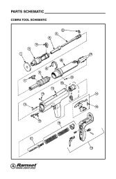
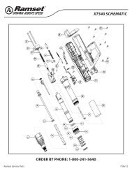
selection GuideTooL DESCRIPTIoN TYPICAL build<strong>in</strong>g trade*.25 cal stripR25n Semi-Automaticn 1 Year Warrantyn Length: 11.6'"n Weight: 4.3 lbs.n Muzzle Bush<strong>in</strong>g O.D.: 3/4"n Maximum P<strong>in</strong> Length: 1-1/2"Walls & Ceil<strong>in</strong>gs.25 cal disc toolsD45An Automatic Piston Returnn 3 Year WarrantyD60n Semi-Automaticn Power Adjustablen 3 Year Warrantyn Length: 15"n Weight: 4.5 lbs.n Muzzle Bush<strong>in</strong>g O.D.: 5/8"n Maximum P<strong>in</strong> Length: 2"n Length: 12-1/2"n Weight: 4.9 lbs.n Muzzle Bush<strong>in</strong>g O.D.: 3/4"n Maximum P<strong>in</strong> Length: 2-3/8"(2-1/2" w/Washer)Walls & Ceil<strong>in</strong>gsElectrical/MechanicalXT540n Automatic Piston Returnn Power Adjustn 3 Year Warrantyn Length: 19'"n Weight: 5.5 lbs.n Muzzle Bush<strong>in</strong>g O.D.: 7/8"n Maximum P<strong>in</strong> Length: 3"Walls & Ceil<strong>in</strong>gs.27 cal strip toolsSA270n Semi-Automaticn Power Adjustn 3 Year WarrantyCOBRAn Semi-Automaticn Economicaln 1 Year Warrantyn Length: 15.3'"n Weight: 5.45 lbs.n Muzzle Bush<strong>in</strong>g O.D.: 5/8"n Maximum P<strong>in</strong> Length: 3"n Length: 13-1/4'"n Weight: 4.5 lbs.n Muzzle Bush<strong>in</strong>g O.D.: 9/16"n Maximum P<strong>in</strong> Length: 2-1/2"(3" w/Washer)Wood fram<strong>in</strong>gWood fram<strong>in</strong>gVIPER IVn Automatic Piston Returnn Designed Specifically forOverhead Applicationsn 3 Year Warrantyn Length: 17'"n Weight: 4.5 lbs.n Maximum P<strong>in</strong> Length: 1-1/2"Acoustical/overhead*Build<strong>in</strong>g trade shown as suggestions. Tools are not limited to <strong>the</strong>se trades.www.ramset.com13
TO THIS BASE MaterialCONCRETESTEEL BEAM - 3/16" to 1/2" THICKFasten This MaterialINTERIOR NON-LOADBEARING DRYWALL TRACK25 - 20 GAGEEXTERIOR PERIMETERDRYWALL TRACK18 -12 GAGECLIPS or BRACKETS forSTEEL FRAMINGFASTENERLENGTH(<strong>in</strong>ches)3/4GASTOOLTF1200T3MAG1-1/4 N.R.1-1/4 N.R.2 x 4 , 2 x 6 LUMBER 2-1/2 N.R.1/2" PLYWOOD 1-1/4 N.R.POWDERTOOLR25POWDER LOAD#3 GRN .25cal STRIPFASTENERLENGTH(<strong>in</strong>ches)GASTOOLPOWDERTOOLPOWDER LOADD45A #2 BRN .25cal DISC TF1200 D45A #4 YEL .25cal DISC1/2721 #2 BRN .22cal SINGLE T3MAG 721 #4 YEL .22cal SINGLER25#4 YEL .25cal STRIPSA270 #3 GRN .27cal STRIP SA270 #4 YEL .27cal STRIPSA270#4 YEL .27cal STRIPSA270#4 YEL .27cal STRIPXT540 #4 YEL .27cal STRIP XT540 #4 YEL .27cal STRIP1/2 N.R.D45A #4 YEL .25cal DISC D45A #4 YEL .25cal DISCCOBRA #4 YEL .27cal STRIP COBRA #4 YEL .27cal STRIPSA270#4 YEL .27cal STRIPSA270#4 YEL .27cal STRIPXT540 #4 YEL .27cal STRIP XT540 #4 YEL .27cal STRIP1/2 N.R.D45A #4 YEL .25cal DISC D45A #4 YEL .25cal DISCCOBRA #4 YEL .27cal STRIP COBRA #4 YEL .27cal STRIPSA270#4 YEL .27cal STRIPSA270#4 YEL .27cal STRIPXT540 #4 YEL .27cal STRIP XT540 #4 YEL .27cal STRIP1-7/8 N.R.COBRA #5 RED .27cal STRIP COBRA #5 RED .27cal STRIPMasterShot #4 YEL .22cal SINGLE MasterShot #4 YEL .25cal DISCSA270#4 YEL .27cal STRIPSA270#4 YEL .27cal STRIPCOBRA #4 YEL .27cal STRIP COBRA #4 YEL .27cal STRIPD45A #4 YEL .25cal DISC1 N.R.D45A #4 YEL .25cal DISCXT540 #4 YEL .27cal STRIP XT540 #4 YEL .27cal STRIP3/4" PLYWOOD1 x 4, 1 x 6 WOOD1-1/2 N.R.SA270 #4 YEL .27cal STRIPSA270 #4 YEL .27cal STRIPCOBRA #4 YEL .27cal STRIP COBRA #4 YEL .27cal STRIP1-1/4 N.R.D45A #4 YEL .25cal DISC D45A #4 YEL .25cal DISCXT540 #4 YEL .27cal STRIP XT540 #4 YEL .27cal STRIP1/2" or 5/8" GYPSUMSHEATHING- N.R. N.R. - N.R. N.R.NOTES:1) This chart is presented as a guide only. Start with <strong>the</strong> lightest load available. If <strong>the</strong> fastener does not completely set, use <strong>the</strong> next higher load and repeat <strong>the</strong> process.2) Product suggestions may not be suitable for all types of base materials.3) N.R. is Not Recommended14 www.ramset.com
POWDER FASTENER &LOAD SELECTION CHARTCONCRETE BLOCK MORTAR JOINT (horizontal only) LIGHT GAGE STEEL 18-12gageFASTENERLENGTH(<strong>in</strong>ches)GASTOOLPOWDERTOOLPOWDER LOADFASTENERLENGTH(<strong>in</strong>ches)GASTOOLPOWDERTOOLPOWDER LOADFASTENERLENGTH(<strong>in</strong>ches)GASTOOLPOWDERTOOLPOWDERLOADR25#3 GRN .25cal STRIPR25#3 GRN .25cal STRIP1TF1200T3MAGD45A #2 BRN .25cal DISC TF1200 D45A #2 BRN .25cal DISC1721 #2 BRN .22cal SINGLE T3MAG 721 #2 BRN .22cal SINGLE- N.R. N.R.SA270 #2 BRN .27cal STRIP COBRA #3 GRN .27cal STRIPSA270#3 GRN .27cal STRIPSA270#3 GRN .27cal STRIP1TF1200T3MAGCOBRA #3 GRN .27cal STRIP TF1200 COBRA #3 GRN .27cal STRIP1D45A #2 BRN .25cal DISC T3MAG D45A #2 BRN .25cal DISC- N.R. N.R.R25 #3 GRN .25cal STRIP R25 #3 GRN .25cal STRIPSA270#3 GRN .27cal STRIPSA270#3 GRN .27cal STRIP1TF1200T3MAGXT540 #3 GRN .27cal STRIP TF1200 COBRA #3 GRN .27cal STRIP1D45A #2 BRN .25cal DISC T3MAG D45A #2 BRN .25cal DISC- N.R. N.R.721 #3 GRN .22cal SINGLE R25 #3 GRN .25cal STRIPSA270#4 YEL .27cal STRIPSA270#4 YEL .27cal STRIP2-1/2 N.R.XT540 #3 GRN .27cal STRIP XT540 #3 GRN .27cal STRIP2-1/2 N.R.COBRA #4 YEL .27cal STRIP COBRA #4 YEL .27cal STRIP- N.R. N.R.MasterShot #4 YEL .22cal SINGLE MasterShot #4 YEL .22cal SINGLESA270#3 GRN .27cal STRIPSA270#3 GRN .27cal STRIP1-1/2 TF1200COBRA #3 GRN .27cal STRIP COBRA #3 GRN .27cal STRIPD45A #3 GRN .25cal DISC1-1/2 TF1200D45A #3 GRN .25cal DISC1-1/2TF1200G2N.R.MasterShot #3 GRN .22cal SINGLE MasterShot #3 GRN .22cal SINGLESA270#3 GRN .27cal STRIPSA270#3 GRN .27cal STRIP2 N.R.COBRA #3 GRN .27cal STRIP COBRA #3 GRN .27cal STRIP2 N.R.D45A #3 GRN .25cal DISC D45A #3 GRN .25cal DISC1-1/2TF1200G2N.R.XT540 #4 YEL .27cal STRIP MasterShot #3 GRN .22cal SINGLE- N.R. N.R. - N.R. N.R. 1-1/2 G2 N.R.www.ramset.com15
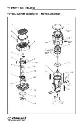
GAS TECHNOLOGYT3MAG• Gas Technology• 45-P<strong>in</strong> Magaz<strong>in</strong>e• <strong>One</strong> Step Fuel Injection• 6 months or 10,000 shotson wearable parts• Length: 18-1/2"• Height: 15"• Weight: 9.2 lbs.• P<strong>in</strong> Guide O.D.: .590• Maximum P<strong>in</strong> Length: 1"ADVANTAGESMost common fastenersPIN #DESCRIPTIONT30121/2" steel p<strong>in</strong> with T3 fuel cellT3012S 1/2" premium steel p<strong>in</strong> with fuel cellT3034B 3/4" concrete p<strong>in</strong> with T3 fuel cellT3034S 3/4" step shank p<strong>in</strong> with T3 fuel cellT31001" concrete p<strong>in</strong> with T3 fuel cellFasteners on page 29.• Higher stick rate• 25% more power• Easy push down force• Deep leg track capacity• 45-p<strong>in</strong> magaz<strong>in</strong>e capabilityFEATURES• Fitted dust shieldT3MAG Increase Your Range withOverhead PowerThe Power of <strong>the</strong> T3MAG allows you toconsistently shoot where no o<strong>the</strong>r gas tool hasgone before. The .125 diameter p<strong>in</strong> is specificallyeng<strong>in</strong>eered to work <strong>in</strong> <strong>the</strong> toughest concrete andsteel where o<strong>the</strong>r p<strong>in</strong>s cannot perform. The newT3MAG system delivers power that rivals o<strong>the</strong>rgas and powder systems.• Battery charger provides constant charg<strong>in</strong>g even withlow voltage drops• 2 Year Warranty or 50,000 shots(6 months on wearable parts or 10,000 shots)• No License RequiredFuel cell and batteryT3 fuel cellPart No. T3FUELReplaces conventionalpowder loads and drivesmore than 1000 p<strong>in</strong>sFuel <strong>in</strong>jection meansno additional steps ofprepar<strong>in</strong>g a fuel cell.Click <strong>the</strong> fuel cell <strong>in</strong> placeand <strong>the</strong> tool is ready to go.Easy battery load<strong>in</strong>g. Battery restposition allows you to turn off <strong>the</strong>tool without fully remov<strong>in</strong>g <strong>the</strong>battery.Settl<strong>in</strong>g aggregate is<strong>the</strong> biggest reason foroverhead p<strong>in</strong> failure.With <strong>the</strong> T3’s 1/2 steel p<strong>in</strong>you can even shoot <strong>in</strong>to <strong>the</strong>web of steel.Part No. B0092The 6-volt Ni-Cd battery can drive morethan 3000 shots per chargeAPPLICATIONSThe T3 has enough power to fasten <strong>in</strong>to hard concrete and steel andstill will not blow through hollow block.Will not spall hollow block like powderactuated.Perfect for hat channel applications.16 www.ramset.com
GAS TECHNOLOGYTRAKFAST TF1200• Gas Technology• Fully Automatic• 1-1/2" P<strong>in</strong> Capacity• 42 P<strong>in</strong> Magaz<strong>in</strong>e CapacityADVANTAGES• SPEED: Three to five times faster thanpowder tools. 42-p<strong>in</strong> magaz<strong>in</strong>e reducesload time.• Length: 17.5"• Height: 15"• EASY TO USE: Tool automatically resetspiston. No recoil, tool absorbs shockresult<strong>in</strong>g <strong>in</strong> less operator fatigue.• Weight: 8.3 lbs.• Maximum Capacity:42 p<strong>in</strong>s• NO LICENSING REQUIRED: Unlike powderactuatedtools, no licens<strong>in</strong>g is required.FEATURES• Maximum cycles/second: 2• Fuel cell: 1000 shots• Battery (charged):3000 shots• NO CHANGING LOADS: TrakFast uses afuel cell, not a load. No need to <strong>in</strong>ventorydifferent colored loads• NARROW NOSE & PROFILE: Allows toolto reach <strong>in</strong>side deep leg track (1-5/8"wide x 2" high).• 2 Year Warranty (6 months on wearableparts).Still <strong>the</strong> most revolutionary fasten<strong>in</strong>g system <strong>in</strong> <strong>the</strong>construction <strong>in</strong>dustry!S<strong>in</strong>ce its <strong>in</strong>troduction <strong>in</strong> 1991, TrakFast has been <strong>the</strong> tool of choice for both <strong>in</strong>terior andexterior contractors. The TrakFast Automatic Fasten<strong>in</strong>g System fastens all types of track,from standard track to hat channel, deep leg, Z, and J channel. Contractors cont<strong>in</strong>ue toreport tremendous sav<strong>in</strong>gs when us<strong>in</strong>g TrakFast for high production fasten<strong>in</strong>g. They havelearned that TrakFast’s actual cost <strong>in</strong> place beats all o<strong>the</strong>r systems. The <strong>in</strong>creased speedand productivity of TrakFast allows <strong>the</strong> contractor to bid more competitively, complete <strong>the</strong>job sooner and move on to <strong>the</strong> next job. Anyone can use TrakFast—just load <strong>the</strong> p<strong>in</strong>s andfire. It’s that easy!TrakFast ICC ESR-2579 is <strong>the</strong> only approval thatallows you to fasten <strong>in</strong>to any location on a hollowblock wall and won’t blow away block like apowder tool.Most common fastenersPIN #P<strong>in</strong> length Most common<strong>in</strong>. (MM) APPLICATIonFPP012S 1/2 12.7 Track to steelFPP034B 3/4 19.1 Track to concreteFasteners on page 29.APPLICATIONSTrakFast’s power comes from<strong>the</strong> battery and fuel cellThe 6-volt rechargeable Ni-CD batterycan drive approximately 3000 shotsper charge. The clean burn<strong>in</strong>g fuel cellcan drive over 1000 p<strong>in</strong>s and keeps<strong>the</strong> tool cleaner than powderactuated tools.Fasten<strong>in</strong>g System ProductivityIn <strong>the</strong> time it takes youto drive two p<strong>in</strong>s witha powder tool, you candrive up to 10 p<strong>in</strong>swith TrakFast!Track to steelLath attachment—us<strong>in</strong>gone-<strong>in</strong>ch TrakFast discs andmagnetic probe adapterFurr<strong>in</strong>g attachment—perfectfasten<strong>in</strong>g every time <strong>in</strong> softand hard base materialsPlywood attachment—us<strong>in</strong>g TrakFast plywood tosteel p<strong>in</strong>Track to concretewww.ramset.com17
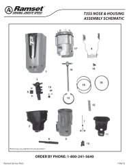
GAS TECHNOLOGYT3SS• Gas Technology• S<strong>in</strong>gle P<strong>in</strong> Gas Tool• Fuel Injection• Cross Over Technology• 2 Year Warranty(6 months on wearableparts)• Length:13-1/2"• Height: 15"• Weight: 7.0 lbs.• P<strong>in</strong> Guide O.D.: 1/2"Standard, 7/8" Magnetic• Maximum P<strong>in</strong> Length:1-1/2"ADVANTAGES• Sets <strong>the</strong> standard for s<strong>in</strong>gle-shotapplications• 5 times faster than traditional drill andanchor methods• Replaces <strong>the</strong> need for tools like <strong>the</strong> DX35• Reduced operator fatigue• Reduced <strong>in</strong>stallation costs—up to 75%• Quiet enough to work <strong>in</strong> tenant occupiedbuild<strong>in</strong>gs• Removable rear foot• Interchange noseVERSATILE, fastens to solid concrete,hollow block, pan deck and steel.APPLICATIONSFEATURESCross<strong>in</strong>g over from powder to gas<strong>Ramset</strong> is serious when it comes to driv<strong>in</strong>g job speed bycreat<strong>in</strong>g <strong>the</strong> T3SS—<strong>the</strong> s<strong>in</strong>gle shot tool that will help movecontractors from powder to gas.The T3SS provides <strong>the</strong> benefits of shoot<strong>in</strong>g a gas tool,<strong>in</strong>clud<strong>in</strong>g reduced <strong>in</strong>stallation time and operator fatigue for<strong>the</strong> contractor who normally shoots a muzzle loadedpowder tool.No more f<strong>in</strong>es for unspent loadson <strong>the</strong> jobsite.To make <strong>the</strong> T3SS <strong>the</strong> most versatile gas tool <strong>in</strong> <strong>the</strong> <strong>in</strong>dustry,Users can change out nosepieces to accommodate any fasten<strong>in</strong>g need. From metal-to-concrete, hardconcrete or steel, pan deck, block and just about surface you can th<strong>in</strong>k of <strong>the</strong> T3SS works for you.Fastener and magnetic nosepieceThe optional <strong>in</strong>terchangeable nosepiece (Part NumberM150200) is able to shoot a variety of M series fasteners.Fuel cell and batteryT3 fuel cellPart No. T3FUELReplaces conventional powderloads and drives more than1000 p<strong>in</strong>s12HSMP034 clip assemblyused to secure conduitM034 fastener used to hangHVAC Duct StrapM100 fastener usedto attach a junctionboxEasy battery load<strong>in</strong>g.Battery rest positionallows you to turn off<strong>the</strong> tool without fullyremov<strong>in</strong>g <strong>the</strong> battery.T3 CupMost common fastenersPIN #Description12HSMP034 1/2" <strong>One</strong> hole strap with 3/4" p<strong>in</strong>MP034TH 3/4" Plated p<strong>in</strong> with top hatM1001" P<strong>in</strong> with gold domed washer14THRHMP034 1/4" Threaded rod hangerFasteners on page 32.Fuel <strong>in</strong>jection meansno additional steps of prepar<strong>in</strong>ga fuel cell. Click <strong>the</strong> fuel cell <strong>in</strong>place and <strong>the</strong> tool is ready to go.Part No. B0092The 6-volt Ni-Cd battery can drivemore than 3000 shots per charge18 www.ramset.com
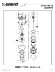
GAS TECHNOLOGYGYPFAST G2• Part No.: GYPFAST• Fully Automatic• 2-1/2" P<strong>in</strong> Capacity• Length: 15"ADVANTAGES• Height: 15.25"• Weight: 7.6lbs.with battery• Lengths: 1-1/2", 2" and2-1/2"• Diameter: .140" Nom<strong>in</strong>al• Head Style: 5/16" dia.bugle head• F<strong>in</strong>ish: Climacoat Long LifePolymer• Exterior Gypsum sheath<strong>in</strong>g to steel fram<strong>in</strong>g• Plywood and OSB sheath<strong>in</strong>g/floor<strong>in</strong>g• Fiber cement panel attachment• Block<strong>in</strong>gFEATURES• Fully automatic system with 150 nailcapacity is 3-5 times faster than screw<strong>in</strong>g.• Fast set-up and tear down – <strong>in</strong>sert battery,fuel cell and nail coil – elim<strong>in</strong>ates need forextension cord, hoses and compressors.• Exterior walls• W<strong>in</strong>dows/door bucks• Specialty exterior sheath<strong>in</strong>g attachment• Woven wire mesh or expanded metal lathto steel fram<strong>in</strong>g• Long life Climacoat f<strong>in</strong>ish is 10 timesmore corrosion resistant than electro-z<strong>in</strong>cplat<strong>in</strong>g.• Woven wire mesh or expanded metal lathto steel fram<strong>in</strong>gFully Automatic Cordless Gas Fasten<strong>in</strong>gSystem for Attach<strong>in</strong>g Exterior Sheath<strong>in</strong>g toLight Gauge Steel Fram<strong>in</strong>gFuel cellPart No. TFUELBatteryPart No. B0092Magnetic Nose ProbePart No. 2761910• Aggressive, patented nail shank designprovides high pullout performance.• 2 year warranty• Contoured bugle head style provides highpullover (w<strong>in</strong>d) resistance.Most common fastenersFasteners on page 31..140" dia. knurled shankPIN # 5/16" dia. bugle head Master carton Application<strong>in</strong>. (MM)GF100 1 25.4 4,800 nails/ctn (48 - 100Metal to Metal Attachmentct. coils) 5 fuel cellsGF112 1-1/2 38.1 6,000 nails/ctn (40- 150ct. coils) 6 fuel cellsGF200 2 50.8 4,800 nails/ctn (32 - 150ct. coils) 5 fuel cellsGF212 2-1/2 63.5 2,700 nails/ctn (18 - 150ct. coils) 3 fuel cellsS<strong>in</strong>gle Layer of Exterior Sheath<strong>in</strong>g, WoodFurr<strong>in</strong>g and Block<strong>in</strong>gDouble Layer of Exterior GypsumSheath<strong>in</strong>g, Wood Furr<strong>in</strong>g and Block<strong>in</strong>gMulti-Layers of Sheath<strong>in</strong>g, Wood Block<strong>in</strong>g,and Dimensional LumberAPPLICATIONSPlated 1" Lath<strong>in</strong>g DiscPart No. LD100Plated 1-1/4" Lath<strong>in</strong>gDisc Part No. LD114Exterior Gypsum sheath<strong>in</strong>g to steel fram<strong>in</strong>g, Plywood and OSB sheath<strong>in</strong>g/floor<strong>in</strong>g, Fiber cementpanel attachment, Block<strong>in</strong>g Exterior walls, W<strong>in</strong>dows/door bucks, Specialty exterior sheath<strong>in</strong>gattachment, Woven wire mesh or expanded metal lath to steel fram<strong>in</strong>g.OSB and plywood to iSPAN joistswww.ramset.com19
Powder fasten<strong>in</strong>gOver a half century of leadership <strong>in</strong> powder actuated tools and fastenersThe first powder actuated tools (PATs) were used for repair<strong>in</strong>g damaged shiphulls dur<strong>in</strong>g World War I. This application cont<strong>in</strong>ued through World War II, when<strong>the</strong> son of <strong>the</strong> orig<strong>in</strong>al <strong>in</strong>ventor, Stanley Temple, developed and implemented <strong>the</strong>technology for commercial use. In 1947, <strong>the</strong> "Tempotool" was <strong>in</strong>troduced to <strong>the</strong>construction <strong>in</strong>dustry.<strong>Ramset</strong> Fasteners was founded <strong>in</strong> 1948 to handle distribution and sales for<strong>the</strong> construction trades. In 1949, <strong>Ramset</strong>’s accredited Operator Program wasofficially launched. Today this highly successful tra<strong>in</strong><strong>in</strong>g program has <strong>in</strong>structedover 1,000,000 trades people <strong>in</strong> <strong>the</strong> safe use of PATs.Onl<strong>in</strong>e Powder Tra<strong>in</strong><strong>in</strong>g and CertificationOnly properly tra<strong>in</strong>ed and licensed operators are described <strong>in</strong> ANSI Standard A10.3 and/or local regulations may operate powder actuated tools. ITW <strong>Ramset</strong>distributors offer complete tra<strong>in</strong><strong>in</strong>g programs for end users. Contact your local<strong>Ramset</strong> distributor for complete details.<strong>Ramset</strong> has designed and eng<strong>in</strong>eered <strong>the</strong> right powder actuated tool (PAT)for your applications. To ensure you use a PAT correctly, please take <strong>the</strong> timeto review <strong>the</strong> Operator’s Safety and Operat<strong>in</strong>g Instruction Manual packagedwith each tool. These manuals are also available for download on <strong>the</strong><strong>Ramset</strong> website.To ensure safety on <strong>the</strong> jobsite, OSHA and ANSI require that all PAT users becometra<strong>in</strong>ed and certified for <strong>the</strong> particular tool be<strong>in</strong>g used. <strong>One</strong> way <strong>Ramset</strong> enablesyou to receive this tra<strong>in</strong><strong>in</strong>g is through our website tra<strong>in</strong><strong>in</strong>g program. This <strong>in</strong>novativeapproach to education comb<strong>in</strong>es <strong>in</strong>teractive web-based tra<strong>in</strong><strong>in</strong>g techniques andonl<strong>in</strong>e test<strong>in</strong>g with immediate feedback to provide you a rich learn<strong>in</strong>g environment.The course consists of approximately 30 pages of usage, safety and troubleshoot<strong>in</strong>gmaterial.Upon completion of this brief course you can take an onl<strong>in</strong>e exam. Withsuccessful completion of <strong>the</strong> exam, you can pr<strong>in</strong>t a certification card.As an <strong>in</strong>dustry leader <strong>in</strong> powder actuated fasten<strong>in</strong>g systems, <strong>Ramset</strong>cont<strong>in</strong>ues to provide <strong>the</strong> most effective and comprehensive <strong>in</strong>structor andoperator tra<strong>in</strong><strong>in</strong>g programs available.Today, <strong>Ramset</strong> cont<strong>in</strong>ues to br<strong>in</strong>g <strong>the</strong> <strong>in</strong>dustry <strong>the</strong> products, service and<strong>in</strong>novation that <strong>the</strong>y have come to expect from <strong>the</strong> leader <strong>in</strong> powder fasten<strong>in</strong>g.All geared to help contractors do <strong>the</strong>ir job faster, more safely and moreproductively.www.ramset.comR25• .25 Caliber Strip Tool• Semi-Automatic• .25 Caliber Strip Loads:3 (Green), 4 (Yellow), 5 (Red)• Weight: 4.3 lbs.ADVANTAGES• Rugged metal hous<strong>in</strong>g• Rubber cushion grip• Length: 11.6"• Maximum P<strong>in</strong> Length: 1-1/2"• 1 Year Warranty• Popular drywall track tool• 1 Year WarrantyMost common fastenersPIN #Shank LengthIN. (MM)Most common application1506B 3/4 19.0 Track to concreteSP58TH 5/8 15.9 Track to steelFasteners start on page 34.COMMON REPLACEMENT PARTS• SC325207A Piston Assembly• SC301011A Shear Clip (Pkg of 3)• SC306010 Fastener Guide• SC326009 Front Barrel/Baseplate20 www.ramset.com
.27 caliber strip TOOLSXT540The most powerful tool <strong>in</strong> its classThe <strong>Ramset</strong> XT540 was specifically designed for <strong>the</strong> commercial framer for heavy-duty <strong>in</strong>terior& exterior applications. The XT540's comb<strong>in</strong>ation of high power and durability make it perfect for<strong>the</strong>se applications:• Driv<strong>in</strong>g 1-1/4” embedment for perimeter track• Fasten<strong>in</strong>g track & clips to structural steel• Track to hard concrete• Excellent compliment to your <strong>Ramset</strong> TrakFast programFeatures• .27 Caliber Strip Tool• Automatic Piston Return• Power Adjust• 3" P<strong>in</strong> Capacity• 3 Year Warranty• Length: 19"• .27 Caliber Strip Loads: • Muzzle Bush<strong>in</strong>g O.D.: 7/8"3 (Green), 4 (Yellow), 5 (Red)• Weight: 7.25 lbs.Durable, Reliable, Powerful, AutomaticADVANTAGES• Very Powerful• Spr<strong>in</strong>g return front end—no manual resett<strong>in</strong>g of <strong>the</strong> piston• Power adjust—dial down 2 full load levels• Rugged soft grip handle• Trigger lock & hand guard to <strong>in</strong>crease safety• Low recoil• Ergonomically balanced• Works with Magnetic Muzzle (Part# 100227)& Lath<strong>in</strong>g DiscsMost common fastenersPIN #Shank LengthIN.(MM)Most common applicationSP58TH 5/8 15.9 Track to steelSP34 3/4 19.1 Track to concreteM100BB 1 25.4 Track to concreteSP114 1-1/4 31.8 Track to concreteWorks with TE (True Embedment) P<strong>in</strong>sFasteners start on page 34.COMMON REPLACEMENT PARTS• PA37037 Piston• 100167 Piston Return Spr<strong>in</strong>g#XTMAGwww.ramset.com21
.27 caliber strip TOOLSSA270• .27 Caliber Strip Tool• Semi-Automatic• Power Adjust• .27 caliber 10-shot striploads: 3 (Green),4 (Yellow), 5 (Red)• Weight: 5.45 lbs.• Length: 15.3"• Muzzle Bush<strong>in</strong>g O.D.: 5/8"• Maximum P<strong>in</strong> Length:3" straight p<strong>in</strong>• 3 Year WarrantyADVANTAGES• Very Powerful• Excellent balance—easy to use all day long• Rubber grip on front barrel—elim<strong>in</strong>ates p<strong>in</strong>ched f<strong>in</strong>gers and hands• Twist lock front end—easy to clean• Rugged polyamide hous<strong>in</strong>g—reduces heattransfer and maximizes operator comfort• Soft, recoil-absorb<strong>in</strong>g handle—for <strong>in</strong>creased operator comfortMost common fastenersPIN #Shank LengthIN. (MM)Most common application1516SDC (washered) 2-1/2 63.5 2" x 4" to concrete1524SDP(washered) 3 76.2 2" x 4" to concreteSP58TH 5/8 15.9 Track to steelFasteners start on page 34.COMMON REPLACEMENT PARTS• 27833 Piston with R<strong>in</strong>gCobra• .27 Caliber Strip Tool• Semi-Automatic• Economical• .27 caliber 10-shot striploads: 3 (Green), 4 (Yellow),5 (Red)• Weight: 4.5 lbs.• Length: 13-1/4"• Muzzle Bush<strong>in</strong>g O.D.: 9/16"• Maximum P<strong>in</strong> Length:2-1/2" (3" w/washer)ADVANTAGES• Semi-automatic .27-caliber tool —uses strip loads• Padded recoil-absorb<strong>in</strong>g handle—for greater operator comfort• Fastens up to 3" standard <strong>Ramset</strong> drivep<strong>in</strong>s and threaded studs—ideal forgeneral construction applications• Full one-year warrantyMost common fastenersPIN #Shank LengthIN. (MM)Most common application1524SDP (washered) 3 76.2 2" x 4" concrete1524SDC (washered) 2-1/2 63.5 2" x 4" concrete1506B 3/4 19.1 Drywall track to concreteFasteners start on page 34.COMMON REPLACEMENT PARTS• SC301200A Piston and R<strong>in</strong>g• SC301012 Pawl (stop)22 www.ramset.com
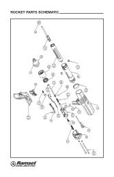
.27 caliber strip TOOLSViper IV• .27 Caliber Strip Tool• Semi-Automatic• Designed Specifically forOverhead ApplicationsADVANTAGES• 3 Year Warranty• Automatic load advance: Load is advancedconsistently each time <strong>the</strong> Viper is fired.• Automatic Piston return: No time spentmanually resett<strong>in</strong>g or cycl<strong>in</strong>g <strong>the</strong> tool. Allowsyou to work faster.• Overdrive Protection: Heavy duty buffersystem prevents front end damage causedby piston overdrive —especially throughsprayed-on <strong>in</strong>sulation.• Open Front-end design: <strong>Complete</strong>lyredesigned open-ended muzzle keeps yourtool cleaner longer.• .27 caliber 10-shot striploads: 3 (Green), 4 (Yellow),5 (Red)• Weight: 4.9 lbs.• Length: 17.25"• Maximum P<strong>in</strong> Length:1-1/2"• Simplified Barrel Retention Collar: No toolsare required for assembly or disassembly.• Stable Steel Collar: The Viper screwssecurely <strong>in</strong>to <strong>the</strong> end of <strong>the</strong> extensionpole with <strong>the</strong> steel collar ensur<strong>in</strong>g a moredurable and rigid connection.• Uses exist<strong>in</strong>g Viper pole system: Works with<strong>the</strong> exist<strong>in</strong>g family of durable <strong>Ramset</strong> poles.FASTENERSTOOL/POLE CONNECTIONThe new poles have an <strong>in</strong>ternal rod, whenactivated by push<strong>in</strong>g on <strong>the</strong> pole sleevetriggers <strong>the</strong> new Viper.PARTNUMBERDESCRIPTIONV4-3 3' PoleV4-6 6' PoleV4-8 8' PoleV4-EXT3' Extension (no trigger)*Telescop<strong>in</strong>g poles are NOT available for <strong>the</strong> VIPER4.Most common fastenersShank LengthPIN #<strong>in</strong>. (MM)Most commonAPPLICATIon14TRHSS10 1 25.4 Threaded Rod HangerSDC125 1-1/4 31.8 Ceil<strong>in</strong>g ClipSPC114 1-1/4 31.8 Ceil<strong>in</strong>g ClipFasteners start on page 34.COMMON REPLACEMENT PARTS• MVP500AP Advance Lever Assembly• MVP140 Piston• electrical p<strong>in</strong>/clip assembliesPreassembled P<strong>in</strong> & Clips for some of <strong>the</strong> mostcommon electrical applications <strong>in</strong>crease jobsite speedfor <strong>the</strong> electrician.• standard p<strong>in</strong>/clip assembliesSDC Fasteners are designed with special dimples on<strong>the</strong> angle clips which act as a shim and assure a snugfit between <strong>the</strong> structural member and <strong>the</strong> clip.• PowerPo<strong>in</strong>t ® P<strong>in</strong>/clip assembliesSPC Fasteners are assembled with <strong>the</strong> patentedtechnology of PowerPo<strong>in</strong>t p<strong>in</strong>s for penetration <strong>in</strong> hardconcrete and steel. The uniform shape and f<strong>in</strong>ish of <strong>the</strong>eng<strong>in</strong>eered tip results <strong>in</strong> more consistent performance<strong>in</strong> your toughest situations.The Viper screws solidlyonto a pole for high reachand secure operation forceil<strong>in</strong>g applications.The Viper was eng<strong>in</strong>eeredspecifically for overheadapplications.www.ramset.com23
.25 caliber disc TOOLSD45A• .25 Caliber Disc Tool• Semi-Automatic• Automatic Piston Return• .25 caliber 10-shot discloads: 2 (Brown), 3 (Green),4 (Yellow), 5 (Red)• Weight: 4.5 lbs.• Length: 15"• Muzzle Bush<strong>in</strong>g O.D.: 5/8"• Maximum P<strong>in</strong> Length:2" (2-1/2" w/washer)• 3 Year WarrantyADVANTAGES• Most durable, powerful powder tool—designed for high production use <strong>in</strong>steel and concrete• Heavy-duty buffer system—preventsfront-end tool damage for longer tool life• 33% faster than semi-automatic tools—saves time and labor costs• <strong>Ramset</strong> Disc Technology—loads onlyadvance after fir<strong>in</strong>g—elim<strong>in</strong>ates 10-20%of load waste3/8" Muzzle Bush<strong>in</strong>gavailable for limitedapplicationsPart Number32330038MMost common fastenersPIN #Shank LengthIN. (MM)Most common applicationSP58TH 5/8 15.9 Track to steelSP12 1/2 12.7 Track to hard steel1506B 3/4 19.1 Track to concreteFasteners on pages 35 and 36.COMMON REPLACEMENT PARTS• 323110 Muzzle Bush<strong>in</strong>g Shroud• 30645 PistonD60• .25 Caliber Disc Tool• Semi-Automatic• Power Adjustable• 3 Year Warranty• .25 caliber 10-shot discloads: 2 (Brown), 3 (Green),4 (Yellow)• Weight: 4.9 lbs.• Length: 12-1/2"• Muzzle Bush<strong>in</strong>g O.D.: 3/4"• Maximum P<strong>in</strong> Length:2-3/8" (2-1/2" w/washer)ADVANTAGES• Quick power adjustment—gives eightlevels of power with only one load levelfor a variety of applications• Rugged polyamide hous<strong>in</strong>g—reducesheat transfer and maximizes operatorcomfort• Soft, recoil-absorb<strong>in</strong>g handle—for<strong>in</strong>creased operator comfort• <strong>Ramset</strong> Disc Technology—loads onlyadvance after fir<strong>in</strong>g—elim<strong>in</strong>ates 10-20%of load wasteMost common fastenersPIN #Shank Length Thread LengthIN. (MM) IN. MMMost common applicationM100BB 1 25.4 Sheet metal to concrete1643W 1 25.4 3/4 19.1 Electrical box to concreteFasteners start on page 34.COMMON REPLACEMENT PARTS• 30691 Piston• 135220 Pawl Assmebly24 www.ramset.com
.22 caliber s<strong>in</strong>gle shot721MASTERSHOT• .22 Caliber S<strong>in</strong>gle Shot Tool• S<strong>in</strong>gle Shot• 3 Year WarrantyADVANTAGES• Rugged metal hous<strong>in</strong>g—holds up for years• Low recoil—reduces operator fatigue onlarge jobs• Simple to clean—saves on labor costs• Rubber cushion grip—for maximumoperator comfort• .22 caliber, s<strong>in</strong>gle-shotloads: 2 (Brown), 3 (Green),4 (Yellow)• Weight: 4.3 lbs.• Length: 13-1/2"• Muzzle Bush<strong>in</strong>g O.D.: 5/8"• Maximum P<strong>in</strong> Length:1-1/2"• Only two mov<strong>in</strong>g parts to clean—easyma<strong>in</strong>tenance; saves time• Narrow 5/8" muzzle bush<strong>in</strong>g—for easyaccess <strong>in</strong> tight fasten<strong>in</strong>g areas• Automatic cartridge ejection system—<strong>in</strong>creases operator speed and productivityMost common fastenersPIN #Shank LengthIN. (MM)Most common application1506B 3/4 19.1 Track to concreteM100BB 1 25.4 Track to concreteSP58TH 5/8 15.9 Track to steelFasteners start on page 34.common replacement parts• 33657 Piston R<strong>in</strong>g Assembly• 12258 Barrel Extension• .22 S<strong>in</strong>gle Shot Tool• Trigger Operated PowderActuate Tool• 90 Day WarrantyADVANTAGES• Designed for frequent use provid<strong>in</strong>gprofessional fasten<strong>in</strong>g results <strong>in</strong> avariety of concrete, masonry or steelapplications• The MasterShot is a traditional triggeroperated tool• Ergonomic design for operator comfort• Uses standard .22 calibers<strong>in</strong>gle shot powder loads:2 (Brown), 3 (Green),4 (Yellow)• Weight: 4.4 lbs.• Length: 15"• Muzzle Bush<strong>in</strong>g O.D.: 3/4"• Maximum P<strong>in</strong> Length: 3"• Positive barrel and load retention preventsbarrel from open<strong>in</strong>g freely, allow<strong>in</strong>g easyhorizontal and overhead fasten<strong>in</strong>g• Powder load automatically ejects aftereach use• Heavy-duty construction2" x 4" to concrete slabTrack to floorMost common fastenersPIN #Shank LengthIN. (MM)Most common application1524SDP (washered) 3 76.2 2" x 4" to concrete1516SDC (washered) 2-1/2 63.5 2" x 4" to concrete1506B 3/4 19.1 Drywall to concreteFasteners start on page 34.www.ramset.com25
t3ss pole toolT3 CUPADVANTAGES• Faster way to put <strong>the</strong> T3ss on a pole• Works with <strong>the</strong> T3ss Gas Tool and updatedViper 4 Poles• No hose clamps required: Simple toassemble• 1 Year warranty on nom<strong>in</strong>al wear and tear• Sturdy designExtend Your Reach!New ergonomic design balances <strong>the</strong> tool directly over <strong>the</strong> pole for a lightweight feeleasy to assembleLog on to www.ramset.com for a video on attach<strong>in</strong>g <strong>the</strong> pole tool to <strong>the</strong> T3SSUses NEW Viper pole system:Works with four newly designed <strong>Ramset</strong>® poles for greater ease and accuracy.V4-EXTTOOL/POLE CONNECTIONThe new poles have an <strong>in</strong>ternal rod, whenactivated by push<strong>in</strong>g on <strong>the</strong> pole sleevetriggers <strong>the</strong> new Viper.PARTNUMBERDESCRIPTIONV4-3 3' PoleV4-6 6' PoleV4-8 8' PoleV4-EXT3' Extension (no trigger)26 www.ramset.com
Tool accessoriesTool Clean<strong>in</strong>g Kitn Wood Handle Wire Brushn Round Wire Brushes:Small, medium, largen Package of 10 Scrubs:Hand and tool cleanersPart No. TFUELFuel Cell–TrackFast (TF1100, TF1200)Gypfast, G2 Qty: 12Part No. T3FUELFuel Cell–T3SS & T3MAGQty: 12 (6–2 packs)Part No. PATCKClean<strong>in</strong>g KitQty: 1Part No. 7505012Battery–TF1100Qty: 1Part No. B0092Battery–T3SS & T3MAGQty: 1Part No. 405176Battery–GYPFASTQty: 1Part No. B0022Battery Charger–TF1100, T3SS & T3MAGQty: 1Part No. 7505142Battery Charger–T2 & R150, E150 & M150Qty: 1Part No. LD100Plated 1" Lath<strong>in</strong>g Disc 22gQty: 1,000 per boxWorks with all magnetic probesPart No. LD114Plated 1-1/4" Lath<strong>in</strong>g Disc(GYPFAST)Qty: 1,000 per boxPart No. 100227Magnetic Muzzle for XT540Qty: 1Part No. 100018Disc Hold<strong>in</strong>g Probe(for TF1100 <strong>One</strong> Piece Nose)Qty: 1Part No. 10041LADisc Hold<strong>in</strong>g Probe(for TF1200 Probe)Qty: 1Part No. M150200Magnetic nose Piece(for R150 and T3SS)Qty: 1Part No. B0237Disc Probe(T3MAG)Qty: 1Part No. 2761910Gas Mag Probe(GYPFAST)Qty: 1Part No. 100342G2 Lath ProbeQty: 128 www.ramset.com
GAS TOOL FASTENERS<strong>Ramset</strong> Collated Gas Tool Fasteners are specifically eng<strong>in</strong>eered for optimalperformance <strong>in</strong> <strong>Ramset</strong> Gas Power Tools us<strong>in</strong>g fastener magaz<strong>in</strong>es.Selection chartT3mag fuel/p<strong>in</strong> pack1000 PINS AND 1 FUEL CELL PER BOX Larger .125 shank diameter offers improved success rate (15 p<strong>in</strong> strip)PART NUMBER PIN LENGTH DESCRIPTIONIN. (MM)T3012 1/2 (12.7) 1/2" steel p<strong>in</strong> with T3 fuel cellT3012S 1/2 (12.7) 1/2" premium steel p<strong>in</strong> with T3 fuel cellT3034B 3/4 (19.1) 3/4" concrete p<strong>in</strong> with T3 fuel cellT3034S* 3/4 (19.1) 3/4" step shank p<strong>in</strong> with T3 fuel cellT3100 1 (25.4) 1" concrete p<strong>in</strong> with T3 fuel cellShank diameter = .125 *Shank diameter= .104/.125Head diameter = .250TrakFast standardfuel/p<strong>in</strong> pack1000 PINS AND 1 FUEL CELL PER BOX For high volume, repetitive fasten<strong>in</strong>gs to concrete and steel such as drywall track to concretePART NUMBER PIN LENGTH DESCRIPTIONIN. (MM)FPP012 1/2 (12.7) 1/2" Plated steel p<strong>in</strong>FPP012S* 1/2 (12.7) 1/2" Premium Plated step shank p<strong>in</strong>FPP034B 3/4 (19.1) 3/4" Black p<strong>in</strong>FPP034S* 3/4 (19.1) 3/4" Premium Plated step shank p<strong>in</strong>FPP100 1 (25.4) 1" Plated p<strong>in</strong>FPP114 1-1/4 (31.8) 1-1/4" Plated P<strong>in</strong>Shank diameter = .109Head diameter = .250* Shank diameter = .104/.118* Head diameter = .250TrakFast breakawayStrip fuel/p<strong>in</strong> pack1000 PINS AND 1 FUEL CELL PER BOXCollation designed to breakaway on impact. For high volume, repetitive fasten<strong>in</strong>gs to concrete suchas wood furr<strong>in</strong>g to concretePART NUMBER PIN LENGTH DESCRIPTIONIN. (MM)FPP034T 3/4 (19.1) 3/4" Plated p<strong>in</strong>FPP100T 1 (25.4) 1" Plated p<strong>in</strong>FPP114T 1-1/4 (31.8) 1-1/4" Plated P<strong>in</strong>FPP112T 1-1/2 (38.1) 1-1/2" Plated P<strong>in</strong>Shank diameter = .109Head diameter = .250Sold <strong>in</strong> master cartons of 5000 m<strong>in</strong>imum. Cartons cannot be split.www.ramset.com29
GAS TOOL FASTENERSPLY138 Trakfast Plywood P<strong>in</strong>for attach<strong>in</strong>g plywoodto metal studs• Fastener Length: 1-3/8"• Shank Diameter: .100 dia. (before knurl)• Head Diameter: .250• Helical Knurled Shank• Mechanical Z<strong>in</strong>c Plated• Can Be Used With:Wood Sheath<strong>in</strong>gs: 3/8", 1/2", 5/8", 3/4"Steel Stud Gauges: 16, 18, 201000 p<strong>in</strong>s and 1 fuel cell per boxAdvantagesvs screws• 3 - 5 times faster than screw <strong>in</strong>stallation. Noworry<strong>in</strong>g about electrical cords.Strip• Collation strip breaks away upon impact,allow<strong>in</strong>g <strong>the</strong> head of <strong>the</strong> p<strong>in</strong> to recess <strong>in</strong>to <strong>the</strong>wood for a nice, clean look• 10-p<strong>in</strong> strips transfer easily from <strong>the</strong> operator’spouch to <strong>the</strong> TrakFast tool, elim<strong>in</strong>at<strong>in</strong>g wastevs air systems• No set-up and tear down time. No hassl<strong>in</strong>g withcompressors or hoses.p<strong>in</strong>s• Hardened steel p<strong>in</strong> ensures a clean penetrationof <strong>the</strong> fastener — no dimpl<strong>in</strong>g of <strong>the</strong> stud• Knurled helical shank gives <strong>the</strong> fastener superiorhold<strong>in</strong>g values• Z<strong>in</strong>c plated for corrosion resistance30 www.ramset.com
T3SS Electrical accessoriesGas tool fasteners(Pre-assembled, S<strong>in</strong>gle-Shot)The fasteners are designed for use <strong>in</strong> <strong>Ramset</strong> S<strong>in</strong>gle-Shot Gas Tools (R150, T3SS)Selection chartThreaded rod hangerU LFor suspended ceil<strong>in</strong>gs, pip<strong>in</strong>g and o<strong>the</strong>r items us<strong>in</strong>g 1/4" or 3/8"threaded rod. Fastener is pre-assembled to a 16 gage threaded rodhanger. 100 per jar.PARTDESCRIPTIONNUMBER14TRHMP0341/4" Rod hanger with 3/4" plated p<strong>in</strong>38TRHMP034Shank diameter = .104/.125 Head diameter = .3003/8" Rod hanger with 3/4" plated p<strong>in</strong>Available <strong>in</strong>convenient jars!<strong>One</strong> hole strapUsed to attach EMT conduit or armored cable to concrete. Fastener preassembledto a 16 gage conduit strap. 100 per jar, 3/8" 200 per jar.PARTDESCRIPTIONNUMBERConduit clamp38HSMP034*3/8" Hole strap with 3/4" plated p<strong>in</strong>U L12HSMP0341/2" Hole strap with 3/4" plated p<strong>in</strong>34HSMP0343/4" Hole strap with 3/4" plated p<strong>in</strong>10HSMP0341" Hole strap with 3/4" plated p<strong>in</strong>Shank diameter = .104/.125 Head diameter = .300 *38HSMP034 = 18 gage, 200 per jarU LUsed to attach conduit to concrete. P<strong>in</strong> pre-assembled to an 18 gageconduit strap. 1/2" 50 per jar and 3/4" 25 per jar.PARTDESCRIPTIONNUMBER12CCMP034L1/2" Conduit clamp with 3/4" plated p<strong>in</strong>34CCMP034L3/4" Conduit clamp with 3/4" plated p<strong>in</strong>Shank diameter = .104/.125 Head diameter = .300The new durable plastic conta<strong>in</strong>ersmean less waste on <strong>the</strong> jobsite, or<strong>in</strong> <strong>the</strong> back of a truck. Their widemouthdesign makes it easy to grabwhat you need.Ceil<strong>in</strong>g Clip AssemblyPre-assembled Ceil<strong>in</strong>g Clip. Plated 14 gage clip. 100 per jar.PARTNUMBERDESCRIPTION34CLIP3/4" wide angle clip w/ 3/4" length p<strong>in</strong>Shank diameter = .104/.125 Head diameter = .300Each T3ss gas accessory and p<strong>in</strong>label provides vital hold<strong>in</strong>g value<strong>in</strong>formation—tak<strong>in</strong>g away <strong>the</strong>guess work.32 www.ramset.com
GAS TOOL FASTENERS(Pre-assembled, S<strong>in</strong>gle-Shot)Selection chartTie strap holderUsed to <strong>in</strong>stall temporary light<strong>in</strong>g and secure low voltage cable to concrete, uses a standard cable tie up to 3/8" <strong>in</strong>width. Fastener is pre-assembled to a 22 gage tie strap holder. 50 per jar.PARTNUMBERTSHMP034Shank diameter = .104/.125 Head diameter = .300DESCRIPTIONTie strap holder with 3/4" plated p<strong>in</strong>Mechanical p<strong>in</strong>with washerMUST USE WITH MAGNETIC WORKCONTACT ELEMENT (M150200)Used for <strong>the</strong> attachment of light gage metal to concrete and steel such as HVAC duct strap to concrete. Plated p<strong>in</strong>pre-assembled to a 1/2" domed washer. 200 per jar, 1" 100 per jar.PARTNUMBERM012M034M034BBM100DESCRIPTION1/2" Plated step p<strong>in</strong> with dome washer3/4" Plated p<strong>in</strong> with domed washer3/4" Premium step p<strong>in</strong> with domed washer1" Plated p<strong>in</strong> with domed washerShank diameter = .125, Step P<strong>in</strong> .104/.118 Head diameter = .300 (M012 = .250)*Will fit R150 & T3SS with optional work contact element, P/N: M1502001/4-20 threaded studNOT MADE IN USAUsed to attach electrical components to concrete where removability of <strong>the</strong> component is required. Plated threadedstud. 200 per jar.PARTNUMBERDESCRIPTIONSHANK LENGTH14STUD 1/2" 5/8"Shank diameter = .125TOP HAT PINUsed for general purpose fasten<strong>in</strong>g to concrete.Plated p<strong>in</strong> with top hat. 200 per jar.PARTNUMBERMPO34THShank diameter = .125 Head diameter = .300DESCRIPTION3/4" Plated p<strong>in</strong> with top hatBridle r<strong>in</strong>gPre-Assembled 2" Bridle R<strong>in</strong>g supports low voltage, data com, signal, and control cables50 per box.PARTDESCRIPTIONNUMBERBR22" Bridal r<strong>in</strong>gShank diameter = .125www.ramset.com33
Powder fastenersThese Mechanical/Electrical Assemblies are designedto be used <strong>in</strong> ei<strong>the</strong>r Gas or Powder Actuated Tools.The unique fastener design <strong>in</strong>creases fasten<strong>in</strong>gsuccess rate while provid<strong>in</strong>g outstand<strong>in</strong>g performance.Selection chartHybrid p<strong>in</strong>For general purpose attachments to concrete.PowerPo<strong>in</strong>t step shank p<strong>in</strong> pre-assembled to 1/2" washer. 500 per jar.PARTNUMBERDESCRIPTIONALL POWDER TOOLSM100BB 1" PowerPo<strong>in</strong>t step shank p<strong>in</strong> with 1/2" domed washer & flute •Shank diameter = .125/.150 Head diameter = .300<strong>One</strong> holeconduit strapUsed to attach EMT conduit or armored cable to concrete.PowerPo<strong>in</strong>t fastener pre-assembled to a 16 gage conduit strap. 100 per box.PARTNUMBERDESCRIPTIONALL POWDER TOOLS38HSSS10 3/8" Hole strap with w/1 premium p<strong>in</strong> •12HSSS10 1/2" Hole strap with w/1 premium p<strong>in</strong> •34HSSS10 3/4" Hole strap with w/1 premium p<strong>in</strong> •10HSSS10 1" Hole strap with w/1-1/4" premium p<strong>in</strong> •Shank diameter = .125/.150 Head diameter = .30038HSSS10 = 18 gageThreadedrod hangerU LFor suspended ceil<strong>in</strong>gs, pip<strong>in</strong>g, and o<strong>the</strong>r items us<strong>in</strong>g 1/4" or 3/8" threaded rod.PowerPo<strong>in</strong>t fastener pre-assembled to a 16 gage threaded rod hanger. 100 per box.PARTNUMBERDESCRIPTIONALL POWDER TOOLS14TRHSS10 1/4" Rod hanger w/1" premium p<strong>in</strong> •38TRHSS10 3/8" Rod hanger w/1" premium p<strong>in</strong> •Shank diameter = .125/.150 Head diameter = .30034 www.ramset.com
POWDER FASTENERSWe ma<strong>in</strong>ta<strong>in</strong> only <strong>the</strong> highest standards <strong>in</strong> <strong>the</strong> materials, production techniques andquality control measures used to manufacture our fasteners, assur<strong>in</strong>g consistent,optimum quality <strong>in</strong> every fastener.FASTENER TERMINOLOGY SUFFIXK = Knurled X = Collated C = 100 countB = Black SD = Washer M = 1000 countE = RamguardTH = Top HatAdvantagesITW <strong>Ramset</strong> powder actuated fasteners are specifically fabricated to meet <strong>the</strong>exact<strong>in</strong>g requirements of toughness and durability that enable <strong>the</strong>m to penetratedense concrete and structural quality steel. All <strong>Ramset</strong> fasteners with .300 head willfit <strong>in</strong>to tools with 8mm barrels.Selection chartBlack track p<strong>in</strong>s Designed for use <strong>in</strong> concrete and structural steel applications. Available <strong>in</strong> 1000-pack per box.PART SHANK LENGTH 721/ ROCKET D60/ SA270 XT540 COBRA MASTERSHOT/NUMBER IN. (MM) R25D45ARS221506B 3/4 (19.1) • • • • • • •Shank diameter = .145 Head diameter = .300plated p<strong>in</strong>s Designed for use <strong>in</strong> concrete and structural steel applications. 100 per box.PART SHANK LENGTH 721/ ROCKET D60/ SA270 XT540 COBRA MASTERSHOT/NUMBER IN. (MM) R25D45ARS221503K 1/2 Knurled (12.7) • • • • • • •1506 3/4 (19.1) • • • • • • •1508 1 (25.4) • • • • • • •1510 1-1/4 (31.8) • • • • • • •1512 1-1/2 (38.1) • • • • • • •1514 2 (50.8) • • • • • •1516 2-1/2 (63.5) • • • •1524 3 (76.2) • • •Shank diameter = .145 Head diameter = .300washered p<strong>in</strong>sWasher <strong>in</strong>creases bear<strong>in</strong>g surface aga<strong>in</strong>st <strong>the</strong> material to be fastened.100 per box. 16 gage metal washer. 7/8" diameter washer after 16 gage.PART SHANK LENGTH 721/ ROCKET D60/ SA270 XT540 COBRA MASTERSHOT/NUMBER IN. (MM) R25D45ARS221506SD 3/4 (19.1) • • • • • • •1508SD 1 (25.4) • • • • • • •1510SD 1-1/4 (31.8) • • • • • • •1512SD 1-1/2 (38.1) • • • • • • •1514SD 2 (50.8) • • • • • • •1516SDC 2-1/2 (63.5) • • • • • •1524SDP* 3 (76.2) • • • •*Square washer <strong>in</strong>dicates 3" p<strong>in</strong> has been <strong>in</strong>stalled Shank diameter = .145 Head diameter = .300www.ramset.com35
POWDER FASTENERSPowerPo<strong>in</strong>t p<strong>in</strong>spowerpo<strong>in</strong>tstep shank p<strong>in</strong>sUsed for fasten<strong>in</strong>g <strong>in</strong>to harder steel and concrete. Premium steel and hard concrete p<strong>in</strong>. 100 per box.PARTNUMBERSHANK LENGTH 721/IN. (MM) R25ROCKET D60/D45ASelection chartSA270 XT540 COBRA MASTERSHOT/RS22SP12 1/2 (12.7) • • • • • • •SP58 5/8 (15.9) • • • • • • •SP34 3/4 (19.1) • • • • • • •Shank diameter = .150 Head diameter = .300Used for fasten<strong>in</strong>g <strong>in</strong>to harder steel and concrete. Premium steel and hard concrete p<strong>in</strong>.P<strong>in</strong> for fasten<strong>in</strong>g <strong>in</strong>to harder steel and concrete. 100 per box. (M100BB 500 per jar)PART SHANK LENGTH 721/ ROCKET D60/ SA270 XT540 COBRA MASTERSHOT/NUMBER IN. (MM) R25D45ARS22M100BB 1 (25.4) • • • • • • •SP100 1 (25.4) • • • • • • •SP114 1-1/4 (31.8) • • • • • • •SP178 1-7/8 (47.6) • • • • • •Shank diameter = .150/.180 Head diameter = .300M100BB shank diameter = .125/.150 with 1/2" washerRamguard p<strong>in</strong>sCoated to improve corrosion resistance <strong>in</strong> treated lumber and o<strong>the</strong>r applications.100 per box. Recommended for threaded lumber applications.PARTNUMBERSHANK LENGTH 721/IN. (MM) R25AUTOFAST D60/D45A ROCKET/SA270XT540 COBRA MASTERSHOT/RS221516SDE 2-1/2 (63.5) • • • • •1524SDE* 3 (76.2) • • • • • •Shank diameter = .145 (SP178E = .150/.180)Head diameter = .300 *Square washer <strong>in</strong>dicates 3" p<strong>in</strong> has been <strong>in</strong>stalled* 1500 Series Coated with RamGuard* SP Series Coated with Triple Z<strong>in</strong>c36 www.ramset.com
POWDER FASTENERSSelection chartTRUE EMBEDMENT PINThe <strong>Ramset</strong> .157 True Embedment P<strong>in</strong> is sized to provide you with True Embedment depths <strong>in</strong> track up to 14gauge. You are assured to meet <strong>the</strong> required embedment depths <strong>in</strong>to concrete or steel without compensat<strong>in</strong>gfor <strong>the</strong> track depth. The p<strong>in</strong> heads are also stamped for easy identification after <strong>in</strong>stallation.T R U E E M B E D M E N TR A M S E T ©Embedment depth iseasily identifiable byhead stamps.Sized a 1/16" longer than nom<strong>in</strong>al length to provide a True Embedment. 100 per box.PARTNUMBERPIN LENGTH EMBEDMENTLENGTHIN. (MM) IN. (MM)721/R25VIPER D60 ROCKET/SA270D45A COBRA XT540TE12 0.545 (13.8) 1/2 (25.4) • • • • • •TE34 13/16 (20.6) 3/4 (31.8) • • • • • •TE100 1-1/16 (27) 1 (25.4) • • • • • •TE114 1-5/16 (33.3) 1-1/4 (31.8) • • • • • •TE112 1-9/16 (39.7) 1-1/2 (38.1) • • • • • •TEC100 1-1/16 (27) 7/8 (22.2) • • • • • •Shank diameter = .157 Head diameter = .32010-P<strong>in</strong> Collated Stips for <strong>the</strong> XT540 with MagPARTNUMBERPIN LENGTH EMBEDMENTLENGTHIN. (MM) IN. (MM)TE12XT 0.545 (13.8) 1/2 (25.4)TE34XT 13/16 (20.6) 3/4 (31.8)TE100XT 1-1/16 (27) 1 (25.4)TE114XT 1-5/16 (33.3) 1-1/4 (31.8)www.ramset.comCeil<strong>in</strong>g clipassembliesPowerPo<strong>in</strong>t p<strong>in</strong>swith ceil<strong>in</strong>g clipsFastenerangle clipDesigned for suspend<strong>in</strong>g ceil<strong>in</strong>gs and o<strong>the</strong>r overhead applications. P<strong>in</strong> preassembled to a 14 gage 45° clip. 1000 per box.PARTPIN LENGTH 721 VIPER D60 ROCKET/ D45A COBRA XT540NUMBERIN.(MM)SA270SDC100 1 (25.4) • • • • • • •SDC125* 1-1/4 (31.8) • • • • • • •*Available <strong>in</strong> 100-Pack (P/N: SDC125C) Shank diameter = .145 Head diameter = .300Designed for difficult overhead applications. P<strong>in</strong> preassembled to a 14 gage angle clip. 1000 per boxPARTPIN LENGTH 721 VIPER D60 ROCKET/ D45A COBRA XT540NUMBERIN.(MM)SA270SPC78 7/8 (22.2) • • • • • • •SPC114 1-1/4 (31.8) • • • • • • •Shank diameter = .150 (SPC114 = .150/.180) Head diameter = .300General purpose 3/4" wide angle clip. 14 gage angle clip. 100 clips per box.PARTNUMBER1202CFHole diameter: 5/16" & 13/64"DESCRIPTIONAngle clip(no p<strong>in</strong>)37
POWDER LOADSHigh Quality and DependabilityITW <strong>Ramset</strong> powder loads and tools match tolerances to provide optimum powerwith<strong>in</strong> recognized national velocity standards. Available <strong>in</strong> color-coded 10-loaddiscs, 10-load strips, and 100-load boxes.Caution Always test-fasten with <strong>the</strong> lowest power level for your tool. If more poweris necessary, use <strong>the</strong> next highest power level until proper level and fasten<strong>in</strong>g isachieved. Refer to operator's manual for more specific details. Observe all safetyrem<strong>in</strong>ders. Tool operators must be tra<strong>in</strong>ed and qualified as required by federal law.Failure to use properly can result <strong>in</strong> serious <strong>in</strong>jury or death to users or bystanders.Now Available - LEAD FREEAdvantages Powder GuidePower level is designated by <strong>the</strong> load level number marked on each box; also by<strong>the</strong> color of <strong>the</strong> box and each powder load. As <strong>the</strong> number <strong>in</strong>creases, <strong>the</strong> powerlevel <strong>in</strong>creases.Disc SeriesRS27 SeriesRS25 Series<strong>Ramset</strong> loads for low velocity toolsPARTNUMBER2D603D604D60POWERLEVEL234COLOR CALIBER/TYPE PACKAGINGBrownGreenYellow.25 Disc.25 Disc.25 Discall 10 disc10 discs/boxCW SeriesRAMSETD60, D45A and AutoFast5D45 5 Red .25 Disc 10 discs/box D45A and AutoFast3RS254RS255RS2522CW32CW42CW345234GreenYellowRedBrownGreenYellow.25 Strip.25 Strip.25 Strip.22 S<strong>in</strong>gle.22 S<strong>in</strong>gle.22 S<strong>in</strong>gle3RS27 3 Green .27 Strip4RS27 4 Yellow .27 Strip5RS27 5 Red .27 Strip6RS27 6 Purple .27 Strip3NL27 3 Green .27 Strip4NL27 4 Yellow .27 Strip5NL27 5 Red .27 Stripall 10 strip10 strips/boxR25COMPATIBLE TOOLSSelection chartOTHERSDX-35all 100/box 721, M70, RS22, HD22, Mastershot DXE37, DXE72all 10 strip10 strips/boxall 10 strip10 strips/boxall 10 strip10 strips/boxall 10 strip10 strips/boxall 10 strip10 strips/boxall 10 strip10 strips/boxall 10 strip10 strips/boxSA270, Cobra, Viper,Rocket and XT540SA270, Cobra, Viper,Rocket and XT540DX-350, DX-351, DX-36M, DX460DX-350, DX-351, DX-36M,DX-451, DX460DX-451, DX-460DX-350, DX-351, DX-36M,DX-451, DX460.25 and .27 caliber strips available <strong>in</strong> 1000 pack*1000-Pak/100 Strips/BoxHilti® is a registered trademark of Hilti, Corp.POWDER LOAD IDENTIFICATION1 2 3 4 5 6Grey Brown Green Yellow Red PurpleLower powerHigher power38 www.ramset.com
PERFORMANCE /SUBMITTAL<strong>Ramset</strong> fasteners may be specified by <strong>the</strong>ir type or catalog number to satisfy fasten<strong>in</strong>g requirements.P<strong>in</strong> specifications• Made from AISI 1060-1065 steel. Austempered to a core hardness of52-56 Rc• Typical tensile strength: 270,000 psi• Typical shear strength: 162,000 psi• Standard f<strong>in</strong>ishesProprietary blackMechanical z<strong>in</strong>c plate to a m<strong>in</strong>imum thickness of .0002 meetsrequirements of ASTM B695—Class 5 Type IElectroplated z<strong>in</strong>c with yellow chromateRamguardApprovals/list<strong>in</strong>gs• iCC Evaluation Service, Inc.#ESR-2579 TrakFast P<strong>in</strong>s• City of Los Angeles#RR-25739 T3 p<strong>in</strong>s#ESR-1955 T3 Fasteners#RR-25264 TrakFast p<strong>in</strong>sCollated Gas Fasteners In Concrete (TrakFast, T2 And T3)PARTNUMBERSERIESFPP -Straight ShankFPP -Step ShankSHANKDIAMETER(INCH)0.109MINIMUMPENETRATION(INCH)INSTALLED IN STONE AGGREGATE CONCRETECONCRETE COMPRESSIVE STRENGTHALLOWABLE LOAD - Ultimate Load2000 PSI 3000 PSI 4000 PSITENSION (LBS) SHEAR (LBS) TENSION (LBS) SHEAR (LBS) TENSION (LBS) SHEAR (LBS)5/8 60 434 55 546 55 453 75 615 55 472 95 6853/4 60 595 80 650 55 583 95 699 55 571 115 7490.104/0.118 3/4 ..... ..... ..... ..... ..... ..... ..... ..... 51 256 83 4182000 PSI 4000 PSI 6000 PSITENSION (LBS) SHEAR (LBS) TENSION (LBS) SHEAR (LBS) TENSION (LBS) SHEAR (LBS)T35/8 83 414 109 611 78 426 80 574 ..... ..... ..... .....0.125Straight Shank3/4 107 541 156 855 104 593 195 977 ..... ..... ..... .....T3 Step Shank 0.104/0.125 5/8 ..... ..... ..... ..... 60 357 117 587 107 533 191 957Collated Gas Fasteners <strong>in</strong> ConcretePARTNUMBERSERIESSHANKDIAMETER(INCH)MINIMUMPENETRATION(INCH)3000 PSILIGHT WEIGHT CONCRETEINSTALLED IN LIGHTWEIGHT CONCRETE / DECK / BLOCKALLOWABLE LOAD - Ultimate Load3000 PSI LIGHT WEIGHTCONCRETE WITH METAL DECKHOLLOW CONCRETE MASONRYUNITS (CMU ANY LOCATION)TENSION (LBS) SHEAR (LBS) TENSION (LBS) SHEAR (LBS) TENSION (LBS) SHEAR (LBS)FPP -5/8 35 234 55 403 30 239 205 1025 35 347 50 4350.109Straight Shank3/4 80 630 100 756 40 330 235 1248 ..... ...... ..... .....FPP -0.104/0.118 3/4 ..... ..... ..... ..... ..... ..... ..... ..... 36 184 58 290Step ShankT35/8 84 418 108 540 72 361 242 1210 20 243 34 2640.125Straight Shank3/4 108 540 173 864 93 470 288 1442 ..... ..... ..... .....T3 Step Shank 0.104/0.125 5/8 ..... ..... ..... ..... 54 269 230 1150 71 357 123 613Note 1: ALLOWABLE loads are shown <strong>in</strong> <strong>the</strong> LARGE BOLD font, Ultimate loads are shown <strong>in</strong> smaller italic font. Note 2: Test<strong>in</strong>g conducted <strong>in</strong> accordance with ICC AC70 & ASTM E1190.Note 3: Safety factors are based on coefficient of variation. In accordance with ICC AC70, <strong>the</strong> safety factor will be no less than 5. Note 4: Values shown <strong>in</strong> concrete are for <strong>the</strong>fastener only. Connected members must be <strong>in</strong>vestigated separately. Note 5: Cyclic, fatigue, shock loads, and o<strong>the</strong>r design criteria may require a different safety factor. Note 6: Jobsite test<strong>in</strong>g may be required to determ<strong>in</strong>e actual job site values. Note 7: M<strong>in</strong>imum edge distance <strong>in</strong> concrete is 3 <strong>in</strong>ches unless o<strong>the</strong>rwise approved. Note 8: For SI: 1 lbf = 4.448 N, 1<strong>in</strong>ch = 25.4 mm, 1 ksi = 6.89MPa. Note 9: T3 straight shank allowable tension value <strong>in</strong> face shell of hollow CMU is 133 lbs.www.ramset.com39
PERFORMANCE /SUBMITTALElectrical Fasteners <strong>in</strong> ConcreteGAS ASSEMBLIESFASTENER PARTNUMBERMP034TH*, M034*M100*, BR2*SHANKDIA.(INCH)0.125MINIMUMPENETRATION(INCH)INSTALLED IN STONE AGGREGATE CONCRETECONCRETE COMPRESSIVE STRENGTHALLOWABLE LOAD - Ultimate Load4000 PSI 6000 PSI3000 PSI Light weightLOWER FLUTETENSION SHEAR TENSION SHEAR TENSION SHEAR(LBS) (LBS) (LBS) (LBS) (LBS) (LBS)HOLLOW BLOCKGrade N, Type 1FACE SHELLM<strong>in</strong> 1-1/4" face thicknessTENSION SHEAR(LBS) (LBS)5/8 78 426 80 574 62 308 .... ..... 72 361 242 1210 133 691 ..... .....3/4 104 593 195 977 132 658 206 1057 93 470 288 1442 84 444 84 44614STUD 0.125 5/8 91 454 ..... ..... 57 373 ..... ..... ..... ..... ..... ..... ..... ..... ..... .....M034BB 0.104/.118 5/8 51 256 83 418 ..... ..... ..... ..... ..... ..... ..... ..... 36 184 58 29034 CLIP 0.104/.125 5/8 62 310 ..... ..... 106 528 ..... ..... 44 220 ..... ..... ..... ..... ..... .....38HSMP034, 12HSMP03434HSMP034, 10HSMP034114HSMP034, 14TRHMP03438TRHMP034, TSHMP03412CCMP034L, 34CCMPO34L0.104/.125 5/8 60 357 117 587 107 533 191 957 54 269 230 1150 71 357 123 613PERFORMANCE / SUBMITTALPOWDER ASSEMBLIESM100BB, 38HSSS1012HSSS10, 34HSSS1010HSSS10, 14TRHSS10,38TRHSS100.125/.150 3/4 107 559 213 1067 161 803 248 1240 96 478 231 1156 102 512 166 831* ESR-1955 p<strong>in</strong> data applies. Note 1: ALLOWABLE loads are shown <strong>in</strong> <strong>the</strong> LARGE BOLD font, Ultimate loads are shown <strong>in</strong> smaller italic font. Note 2: Test<strong>in</strong>g conducted <strong>in</strong> accordancewith ICC AC70 & ASTM E1190 Note 3: Safety factors are based on coefficient of variation. In accordance with ICC AC70, <strong>the</strong> safety factor will be no less than 5. Note 4: Valuesshown <strong>in</strong> concrete are for fastener only. Connected members must be <strong>in</strong>vestigated separately. Note 5: Cyclic, fatigue, shock loads and o<strong>the</strong>r design criteria may require a differentsafety factor. Note 6: Job-site test<strong>in</strong>g may be required to determ<strong>in</strong>e actual job site values. Note 7: M<strong>in</strong>imum edge distance is 3 <strong>in</strong>ches unless o<strong>the</strong>rwise approved. In hollow blockapplications, no more than one fastener per cell. Note 8: For SI: 1 lbf = 4.448 N, 1 <strong>in</strong>ch = 25.4 mm, 1 ksi = 6.89MPa. Note 9: 20 ga metal deck.Gas Fasteners <strong>in</strong> SteelPARTNUMBERSHANKDIAMETER(INCH)TYPE OFSHANKINSTALLED IN A36 STRUCTURAL STEELSTEEL THICKNESS INCHESALLOWABLE LOAD - Ultimate Load3/16 (.1875) 1/4 (.250) 3/8 (.375)TENSION (LBS) SHEAR (LBS) TENSION (LBS) SHEAR (LBS) TENSION (LBS) SHEAR (LBSFPP012 0.109 SMOOTH 195 1047 292 1570 223 1220 278 1526 181 1048 7 186 1076 7M012FPP012S0.104/0.118 SMOOTH ..... ..... ..... ..... 148 744 157 787 166 832 7 157 787 7T3012 0.125 SMOOTH 63 676 162 1356 239 1285 211 1417 113 914 8 197 1327 8T3012S 0.125TAPERSMOOTH183 958 332 1660 237 1184 356 1782 189 943 10 392 1960 7INSTALLED IN ASTM A 572 GRADE 50 STEELSTEEL THICKNESS INCHEST3012 0.125 SMOOTH 103 733 222 1682 147 950 119 973 147 856 9 112 1014 9Note 1: ALLOWABLE loads are shown <strong>in</strong> <strong>the</strong> LARGE BOLD font, Ultimate loads are shown <strong>in</strong> smaller italic font. Note 2: Test<strong>in</strong>g conducted <strong>in</strong> accordance with ICC AC70 & ASTM E1190.Note 3: Safety factors are based on coefficient of variation. In accordance with ICC AC70, <strong>the</strong> safety factor will be no less than 5. Note 4: Cyclic, fatigue, shock loads and o<strong>the</strong>r designcriteria may require a different safety factor. Note 5: Job site test<strong>in</strong>g may be required to determ<strong>in</strong>e actual job site values. Note 6: Values shown are for fasten<strong>in</strong>gs that have <strong>the</strong> entirepo<strong>in</strong>ted end of <strong>the</strong> fastener driven through <strong>the</strong> steel plate; except as noted below. Note 7: Fastener penetration is .31" m<strong>in</strong>imum. Note 8: Fastener penetration is .29" m<strong>in</strong>imum.Note 9: Fastener penetration is .27" m<strong>in</strong>imum. Note 10: Fastener penetration is .25" m<strong>in</strong>imum. Note 11: For SI: 1 lbf = 4.448 N, 1 <strong>in</strong>ch = 25.4 mm, 1 ksi = 6.89MPa40 www.ramset.com
PERFORMANCE /SUBMITTALPLY138 TrakFast Plywood to Steel P<strong>in</strong> Performance TablesALLOWABLE SHEAR FOR WIND OR SEISMIC FORCES IN POUNDS PER FOOT FOR HORIZONTAL PLYWOOD DIAPHRAGMS WITH STEEL FRAMINGPLYWOODGRADEStructural 1Grades o<strong>the</strong>r thanStructural 1MINIMUMSTEELGAGE 4, 620162016MINIMUMPANELTHICKNESS(Inches)7/1615/327/1615/32BLOCKED DIAPHRAGM PIN SPACING (Inches) 5, 6P<strong>in</strong> spac<strong>in</strong>g at diaphragm boundaries (all cases), atcont<strong>in</strong>uous panel edges parallel to load(cases 3 &4) and at <strong>the</strong> panel edges (cases 5 & 6)ALLOWABLE LOADUNBLOCKED DIAPHRAGM PINSPACING (Inches) 5, 6P<strong>in</strong>s spaced 6 <strong>in</strong>ches max.at supported edges6 4 2-1/2 2 Case 1P<strong>in</strong> spac<strong>in</strong>g at o<strong>the</strong>r panel edges(no unblocked edges6 6 4 3or cont<strong>in</strong>uous jo<strong>in</strong>tsparallel to load)185 280 420475185205 305 460520205165185250275380415430470165185All o<strong>the</strong>rconfigurations(cases 2, 3, 4, 5 & 6)Note 1: These values are for short-time loads due to w<strong>in</strong>d or earthquake and shall be reduced by 25 percent for normal load<strong>in</strong>g. Note 2: The p<strong>in</strong> shall be long enoughto penetrate through <strong>the</strong> thickness of <strong>the</strong> steel a m<strong>in</strong>imum of 1/4 <strong>in</strong>ch. Note 3: M<strong>in</strong>imum width of fram<strong>in</strong>g is 1-1/2 <strong>in</strong>ches. Note 4: These shear values also apply tofram<strong>in</strong>g made of thicker steel. Note 5: Spac<strong>in</strong>g of fasteners along <strong>in</strong>termediate fram<strong>in</strong>g members is 12 <strong>in</strong>ches on center. Note 6: The m<strong>in</strong>imum panel edge distanceis 3/8 <strong>in</strong>ch. Note 7: Values shown reflect a 5:1 safety factor. Note 8: For SI: 1 lbf = 4.448 N, 1 <strong>in</strong>ch = 25.4 mm, 1 ksi = 6.89MPaNote: Fram<strong>in</strong>g is permitted to be oriented <strong>in</strong> ei<strong>the</strong>r direction for diaphragms, provided sheath<strong>in</strong>g is designed for vertical load<strong>in</strong>g.ALLOWABLE WITHDRAWAL LOADS IN POUNDS PER FASTENER DUE TO WIND OR SEISMIC FORCES FOR PLYWOOD AND LUMBER ATTACHED TO STEELFRAMING 1, 2, 3, 4PIN DIAMETER(Inches)MINIMUM STEELTHICKNESS(Gage or Inches)MINIMUM THICKNESS OF PLYWOOD (Inches)ALLOWABLE LOAD - Ultimate Load3/8 7/16 15/32 19/320.100 22 15 15 ..... .....0.100 20 20 25 25 250.100 18 30 35 40 400.100 16 40 45 60 60Note 1: Plywood shall be Structural 1 rated. For o<strong>the</strong>r grades, values shall be reduced by 10 percent. Note 2: These values are for loads due to w<strong>in</strong>d or earthquakeand shall be reduced by 25 percent for o<strong>the</strong>r applications. Note 3: M<strong>in</strong>imum panel edge distance is 3/8 <strong>in</strong>ch. Note 4: The p<strong>in</strong> shall be long enough to penetratethrough <strong>the</strong> metal a m<strong>in</strong>imum of 1/4 <strong>in</strong>ch. Note 5: Values shown reflect a 8:1 safety factor. Note 6: For SI: 1 lbf = 4.448 N, 1 <strong>in</strong>ch = 25.4 mm, 1 ksi = 6.89MPa140150125140Electrical Fasteners <strong>in</strong> concrete / Gas Fasteners <strong>in</strong> STeel / PLY138 TrakFast Plywood to Steel P<strong>in</strong>www.ramset.com41
PERFORMANCE /SUBMITTALPERFORMANCE / SUBMITTALPLY138 TrakFast Plywood to Steel P<strong>in</strong> Performance TablesALLOWABLE SHEAR FOR WIND FORCES IN POUNDS PER FOOT FOR PLYWOOD SHEAR WALLS WITH STEEL FRAMINGPLYWOODGRADEStructural 1Grades o<strong>the</strong>r thanStructural 1MINIMUM STEELGAGE 5MINIMUM PANELTHICKNESS (Inches)PIN SPACING, ALL PANEL EDGES (Inches)ALLOWABLE LOAD6 4 3 222 3/8 6 120 180 240 30522 7/16 6 130 195 260 33022 15/32 145 215 290 36520 3/8 6 155 235 310 39520 7/16 6 170 255 340 43520 15/32 205 305 410 52022 3/8 6 110 165 215 27522 7/16 6 120 175 235 30022 15/32 130 195 260 33020 3/8 6 140 210 280 36020 7/16 6 155 230 310 39020 15/32 185 275 370 470Note 1: Values are for loads imposed by w<strong>in</strong>d and shall be reduced by 25 percent for normal load<strong>in</strong>g. Note 2: The p<strong>in</strong> shall be long enough to penetrate through <strong>the</strong>metal fram<strong>in</strong>g a m<strong>in</strong>imum of 1/4 <strong>in</strong>ch. Note 3: The m<strong>in</strong>imum panel edge distance for p<strong>in</strong> placement is 3/8 <strong>in</strong>ch. Note 4: Spac<strong>in</strong>g of fasteners along <strong>in</strong>termediatefram<strong>in</strong>g members is 6 <strong>in</strong>ches on center for 3/8 <strong>in</strong>ch and 7/16 <strong>in</strong>ch panels when studs are 24 <strong>in</strong>ches on center and 12 <strong>in</strong>ches on center when studs are 16 <strong>in</strong>cheson center. For o<strong>the</strong>r panel thickness, spac<strong>in</strong>g along <strong>in</strong>termediate fram<strong>in</strong>g members is 12 <strong>in</strong>ches from center. Note 5: Fram<strong>in</strong>g to be spaced 24 <strong>in</strong>ches on center orcloser except as provided <strong>in</strong> Footnote 6. Note 6: The values for 3/8-<strong>in</strong>ch and 7/16-<strong>in</strong>ch panels may be <strong>in</strong>creased by 20 percent and 10 percent, respectively, forfram<strong>in</strong>g spaced 16 <strong>in</strong>ches on center. Note 7: Values shown reflect a 5:1 safety factor. Note 8: For SI: 1 lbf = 4.448 N, 1 <strong>in</strong>ch = 25.4 mm, 1 ksi = 6.89MPaALLOWABLE LATERAL LOADS IN POUNDS PER FASTENER DUE TO WIND OR SEISMIC FORCES FOR STRUCTURAL 1 PLYWOOD AND LUMBER ATTACHED TOSTEEL FRAMING1, 2, 3, 4, 6PIN DIAMETER(INCHES)MINIMUM PANELTHICKNESS (Inches)MINIMUM THICKNESS OF PLYWOOD (Inches)ALLOWABLE LOAD3/8 7/16 15/32 19/32 23/32 1-1/80.100 22 80 80 80 80 80 800.100 20 105 105 115 115 115 1150.100 16 105 105 115 170 170 170Note 1: Plywood shall be Structural 1 rated. For o<strong>the</strong>r grades, values shall be reduced by 10 percent. Note 2: These values are for loads due to w<strong>in</strong>d or earthquake andshall be reduced by 25 percent for o<strong>the</strong>r applications. Note 3: M<strong>in</strong>imum panel edge distance for placement is 1 <strong>in</strong>ch from <strong>the</strong> fastener to <strong>the</strong> sheath<strong>in</strong>g edge measured<strong>in</strong> <strong>the</strong> direction of <strong>the</strong> load and 3/8 <strong>in</strong>ch measured perpendicular to <strong>the</strong> direction of <strong>the</strong> load. Note 4: The p<strong>in</strong> shall be long enough to penetrate through <strong>the</strong> metal am<strong>in</strong>imum of 1/4 <strong>in</strong>ch. Note 5: Values for 16 gage also apply to 14 gage. Note 6: The above values apply to groups of at least five fasteners. For fewer fasteners <strong>in</strong> agroup, use one-half of <strong>the</strong> tabulated value. Note 7: Values shown reflect a 5:1 safety factor. Note 8: For SI: 1 lbf = 4.448 N, 1 <strong>in</strong>ch = 25.4 mm, 1 ksi = 6.89MPa42 www.ramset.com
PERFORMANCE /SUBMITTALGypFast fasteners for <strong>the</strong> attachment of gypsum sheath<strong>in</strong>g to light gage steel fram<strong>in</strong>gp<strong>in</strong> specifications• Made from AISI 1060-1065 steel. Austempered to a core hardness of 52-56 Rc• Typical tensile strength: 270,000 psi• Typical shear strength: 162,000 psi• Standard f<strong>in</strong>ishesMechanical z<strong>in</strong>c plate to a m<strong>in</strong>imum thickness of .0002 meetsrequirements of ASTM B695Climacoatapprovals/list<strong>in</strong>gs• iCC Evaluation Service, Inc.#ESR-2174 GypFast Gypsum Sheath<strong>in</strong>g#ER-5380 GypFast Plywood Sheath<strong>in</strong>g• City of Los Angeles#RR-25638 GypFastAllowable Negative Loads Us<strong>in</strong>g <strong>Ramset</strong> GypFast FastenersSHEATHING TYPE1/2" GP DensGlass Gold ExteriorSheath<strong>in</strong>g5/8" GP DensGlass Gold FireguardType X Sheath<strong>in</strong>g1/2" USG SheetrockBrand Sheath<strong>in</strong>g5/8" USG Sheetrock Brand Fire CodeType X Sheath<strong>in</strong>g1/2" USG FiberockBrand Aquatough5/8" USG SecurockGlass-Mat Sheath<strong>in</strong>g5/8" Certa<strong>in</strong>Teed GlasRocSheath<strong>in</strong>g Type X5/8" Certa<strong>in</strong>Teed GlasRocSheath<strong>in</strong>g Type XNational Gypsum e2XPExtended Exposure Sheath<strong>in</strong>gMINIMUM STEELSTUD GAGE20g to 12g20g to 12g20g to 12g20g to 12g20g to 12gMAXIMUM STEELSTUD SPACING (<strong>in</strong>)FASTENER SPACING (<strong>in</strong>)ALLOWABLE NEGATIVELOAD (psf)24 8 616 8 824 8 2416 8 3224 8 1216 8 1624 8 1816 8 2424 8 3016 8 4018g 16 8 3518g 24 8 2016g 24 8 1818g 16 8 39Note 1: Tested <strong>in</strong> accordance with ASTM E330. Note 2: Values shown reflect a 3:1 safety factor. Note 3: The fasteners must be driven to a depth at which <strong>the</strong> shank pierces <strong>the</strong>steel, such that <strong>the</strong> tip protrudes from <strong>the</strong> base metal a m<strong>in</strong>imum of 1/2-<strong>in</strong>ch. Note 4: Tabulated values do not allow any overdriv<strong>in</strong>g of fasteners <strong>in</strong>to sheath<strong>in</strong>g.PLY138 TrakFast Plywood to Steel P<strong>in</strong> / GypFast Fastenerscorrosion data astm b117 salt sprayGF112S-12 SELF DRILL SCREW1560 hours (10% Red Rust) Driven3240 Hours (10% Red Rust) UnDriven 24 Hours (5% Red Rust)GypFast Fastener has Climacoat Long Life Polymer Coat<strong>in</strong>g; S-12 Screw has .0002" Electroz<strong>in</strong>c and Clear Chromate.www.ramset.com43
PERFORMANCE /SUBMITTALGypFast fasteners for <strong>the</strong> attachment of plywood sheath<strong>in</strong>g to light gage steel fram<strong>in</strong>gp<strong>in</strong> specifications• Made from AISI 1060-1065 steel. Austempered to a core hardness of 52-56 Rc• Typical tensile strength: 270,000 psi• Typical shear strength: 162,000 psi• Standard f<strong>in</strong>ishesMechanical z<strong>in</strong>c plate to a m<strong>in</strong>imum thickness of .0002 meets requirementsof ASTM B695Climacoatapprovals/list<strong>in</strong>gs• iCC Evaluation Service, Inc.#ESR-2174 GypFast Gypsum Sheath<strong>in</strong>g#ER-5380• City of Los Angeles#RR-25638 GypFastGypFast Plywood Sheath<strong>in</strong>gAllowable Withdrawl and Lateral Loads For A GypFast Fastener Used to Attach StructuralPlywood Panels to Steel Fram<strong>in</strong>g Members 1,2,3PERFORMANCE / SUBMITTALMINIMUM STEEL MINIMUM THICKNESS OF STRUCTURAL PANELS MINIMUM THICKNESS OF STRUCTURAL PANELSTHICKNESS(gage) 4 3/8 Inch 15/32 Inch 19/32 Inch 23/32 Inch 3/8 Inch 15/32 Inch 19/32 Inch 23/32 InchWithdrawl Loads (pounds)Lateral Loads (pounds)14 90 90 95 120 135 160 190 21516 90 90 90 110 135 160 165 18518 90 90 90 90 135 160 160 16020 70 70 70 70 110 130 130 13022 50 50 50 50 110 110 110 110For SI: 1 Inch = 25.4 mm, 1 Pound = 4.448 N.1 Tabulated values are for loads due to w<strong>in</strong>d or earthquake, and must be reduced by 25 percent for o<strong>the</strong>r applications.2 Tabulated values allow for no more than 20 percent of <strong>the</strong> fasteners to be overdriven more than 1/16 <strong>in</strong>ch.3 M<strong>in</strong>imum edge distance and spac<strong>in</strong>g are 3/8 <strong>in</strong>ch and 3 <strong>in</strong>ches, respectively.4 Section 2.2.3 describes m<strong>in</strong>imum base-material thicknesses associated with gages.Allowable Shear for W<strong>in</strong>d Forces For Structural Plywood Shear Walls Attached to Light GageSteel Studs With GypFast Fasteners 1,2,3 (pounds per foot)PANEL TYPEStructural I orRated Sheath<strong>in</strong>gand Sid<strong>in</strong>gMINIMUM PANELTHICKENESSFRAMINGFASTENER SPACING 4,5(INCHES ON CENTER)MINIMUN GAGE 6 SPACING (INCHES ON CENTER) 6 4 3 23/816 180 270 360 4593/8 2224 144 216 288 36715/32 16 or 24 170 255 340 4333/816 180 270 360 4593/8 2024 144 216 288 36715/32 16 or 24 208 313 417 5313/816 214 321 428 5463/8 24 171 257 342 43715/32 1816 or 24 253 380 506 64519/32 16 or 24 259 389 518 66123/32 16 or 24 259 389 518 66119/3216 or 24 266 399 532 6791623/32 16 or 24 296 445 593 75619/3216 or 24 304 456 608 7761423/32 16 or 24 345 517 690 879For SI: 1 Inch = 25.4 mm, 1 Pound/L<strong>in</strong>eral Foot = 0.0146 N/mm.44 www.ramset.com
PERFORMANCE/SUBMITTAL<strong>Ramset</strong> fasteners may be specified by <strong>the</strong>ir type or catalog number to satisfy fasten<strong>in</strong>g requirements.P<strong>in</strong> specifications• Made from AISI 1060-1065 steel. Austempered to a core hardness of 52-56 Rc• Typical tensile strength: 270,000 psi• Typical shear strength: 162,000 psi• Standard f<strong>in</strong>ishesProprietary blackMechanical z<strong>in</strong>c plate to a m<strong>in</strong>imum thickness of .0002 meets requirementsof ASTM B695—Class 5 Type 1RamguardFASTENERS IN NORMAL WEIGHT CONCRETEPARTNUMBER SERIESSHANKDIAMETER(INCH)1500/1600 SERIES 0.145MINIMUMPENETRATION(INCH)INSTALLED IN STONE AGGREGATE CONCRETECONCRETE COMPRESSIVE STRENGTHALLOWABLE LOAD - Ultimate Load2000 PSI 4000 PSI 6000 PSITENSION (LBS) SHEAR (LBS) TENSION (LBS) SHEAR (LBS) TENSION (LBS) SHEAR (LBS)3/4 50 655 66 739 100 511 104 552 ..... ..... ..... .....1 152 943 166 1229 157 937 182 1342 ..... ..... ..... .....1-1/4 159 1078 265 1665 179 1043 267 1538 ..... ..... ..... .....1-1/2 154 1450 340 2027 209 1357 342 1712 ..... ..... ..... .....SP 0.150 3/4 ..... ..... ..... ..... 150 803 105 786 81 493 82 454SP SERIES .150/.180Approvals/list<strong>in</strong>gs• iCC Evaluation Service, Inc.#ESR-2690 Sill Plate#ESR-1799 Powder P<strong>in</strong>s & Clips• City of Los Angeles#RR-22668 Powder p<strong>in</strong>s1 154 1043 200 1173 243 1307 175 1037 189 1125 210 11771-1/4 207 1553 230 1636 298 1749 218 1471 213 1568 305 17801-1/2 ..... ..... ..... ..... 384 2126 391 1957 239 1886 594 29681900 0.145 3/4 105 694 71 458 101 685 99 627 ..... ..... ..... .....Note 1: ALLOWABLE loads are shown <strong>in</strong> <strong>the</strong> LARGE BOLD font, Ultimate loads are shown <strong>in</strong> smaller italic font. Note 2: Test<strong>in</strong>g conducted <strong>in</strong> accordance with ICC AC70& ASTM E1190. Note 3: Safety factors are based on coefficient of variation. In accordance with ICC AC70, <strong>the</strong> safety factor will be no less than 5. Note 4: Valuesshown <strong>in</strong> concrete are for <strong>the</strong> fastener only. Connected members must be <strong>in</strong>vestigated separately. Note 5: Cyclic, fatigue, shock loads, and o<strong>the</strong>r design criteriamay require a different safety factor. Note 6: Job site test<strong>in</strong>g may be required to determ<strong>in</strong>e actual job site values. Note 7: M<strong>in</strong>imum edge distance is 3 <strong>in</strong>ches unlesso<strong>the</strong>rwise approved. Note 8: For SI: 1 lbf = 4.448 N, 1 <strong>in</strong>ch = 25.4 mm, 1 ksi = 6.89MPaFAsteners <strong>in</strong> normal Weight concrete / SteelInstalled <strong>in</strong> Concrete - Concrete Compressive StrengthPART NUMBERSERIESSHANK DIATE 0.157TEC100 90°Ceil<strong>in</strong>g Clip3000 Lt Wt on W Deck4000psi Normal Wt 6000psi Normal WtEMBEDLower FluteTension Shear Tension Shear Tension Shear3/4 71 137 109 142 106 2651 278 216 214 400 152 3271-1/4 377 317 415 349 164 3301-1/2 242 479 ----- ----- 238 4480.157 7/8 207 ----- ----- ----- 88 -----Notes:1) Fasteners tested to ASTM E1190 &ICC-ES AC70 (March 1, 2010)2) Allowable loads are shown3) Allowable loads and safety factorsare based on coefficient of variation <strong>in</strong>accordance with ICC AC70, <strong>the</strong> safetyfactor will be no less than 54) Values shown for steel basematerials have <strong>the</strong> po<strong>in</strong>ted end of <strong>the</strong>fastener driven through <strong>the</strong> steel plateInstalled <strong>in</strong> A36 Structural SteelPART NUMBERSERIESSHANK DIASHANKTYPE3/16 1/4 3/8 1/2Tension Shear Tension Shear Tension Shear Tension ShearTE 0.157 KNURLED 323 606 562 673 934 820 603 766Installed <strong>in</strong> A572-GR50 Structural SteelPART NUMBERSERIESSHANK DIASHANKTYPE3/16 1/4 3/8 1/2Tension Shear Tension Shear Tension Shear Tension ShearTE 0.157 KNURLED 442 676 630 662 760 725 582 532www.ramset.com45
Performance/submittalFastener In SteelPARTNUMBERSERIESSHANKDIA(INCH)TYPE OFSHANKTENSION(LBS)INSTALLED IN A36 STRUCTURAL STEEL-STEEL THICKNESS (INCHES)ALLOWABLE LOAD - Ultimate Load3/16 1/4 3/8 1/2 3/4SHEAR(LBS)TENSION(LBS)SHEAR(LBS)TENSION(LBS)SHEAR(LBS)TENSION(LBS)SHEAR(LBS)TENSION(LBS)1500/SMOOTH 81 790 373 2039 181 1269 273 1642 397 2169 489 2771 243 1328 8 277 1514 8 ..... ..... ..... .....0.1451600KNURLED 296 1633 636 3516 584 3384 659 3822 680 3755 730 4030 253 1459 8 293 1632 8 ..... ..... ..... .....SP 0.150 SMOOTH 385 2107 662 3618 445 2549 477 2736 393 2145 574 3137 948 5180 597 3500 234 1244 8 356 1895 8SHEAR(LBS)PERFORMANCE / SUBMITTALPARTNUMBERSERIESSHANKDIA(INCH)TYPE OFSHANKTENSION(LBS)INSTALLED IN A572 GRADE 50 STRUCTURAL STEEL-STEEL THICKNESS (INCHES)ALLOWABLE LOAD - Ultimate Load3/16 1/4 3/8 1/2 3/4SHEAR(LBS)TENSION(LBS)SHEAR(LBS)TENSION(LBS)SHEAR(LBS)TENSION(LBS)SHEAR(LBS)TENSION(LBS)1500/SMOOTH ..... ..... ..... ..... ..... ..... ..... ..... ..... ..... ..... ..... ..... ..... ..... ..... ..... ..... ..... .....0.1451600KNURLED 260 1609 499 3182 579 3411 725 4272 383 2216 7 595 3431 7 ..... ..... ..... ..... ..... ..... ..... .....SP 0.150 SMOOTH 356 2123 569 3394 554 3232 637 3710 604 3447 602 3437 814 4473 9 820 4503 9 243 1362 8 381 2141 8Note 1: ALLOWABLE loads are shown <strong>in</strong> <strong>the</strong> LARGE BOLD font, Ultimate loads are shown <strong>in</strong> smaller italic font. Note 2: Test<strong>in</strong>g conducted <strong>in</strong> accordance with ICC AC70& ASTM E1190. Note 3: Safety factors are based on coefficient of variation. In accordance with ICC AC70, <strong>the</strong> safety factor will be no less than 5. Note 4: Cyclic,fatigue, shock loads, and o<strong>the</strong>r design criteria may require a different safety factor. Note 5: Job site test<strong>in</strong>g may be required to determ<strong>in</strong>e actual job site values.Note 6: Values shown are for fasten<strong>in</strong>gs that have <strong>the</strong> entire po<strong>in</strong>ted end of <strong>the</strong> fastener driven through <strong>the</strong> steel plate; except as noted below. Note 7: Fastenerpenetration is 3/8" m<strong>in</strong>imum. Note 8: Fastener penetration is 7/16" m<strong>in</strong>imum. Note 9: Fastener penetration is 1/2" m<strong>in</strong>imum Note 10: For SI: 1 lbf = 4.448 N, 1 <strong>in</strong>ch= 25.4 mm, 1 ksi = 6.89MPaFastener In Lightweight ConcretePARTNUMBER SERIESSHANKDIAMETER(INCH)1500 SERIES 0.145SP SERIES .150/.180MINIMUMPENETRATION(INCH)ALLOWABLE WORKING VALUES INSTALLED IN 3000 PSI LIGHTWEIGHT CONCRETEALLOWABLE LOAD - Ultimate Load3000 PSI LIGHTWEIGHT W/DECKING 3000 PSI LIGHTWEIGHTLOWER FLUTE TENSION LOWER FLUTE SHEAR TENSION SHEAR3/4 76 395 260 1409 167 837 179 8941 134 668 265 1505 200 998 228 11411-1/4 157 784 269 1344 333 1664 400 20901-1/2 233 1163 346 1728 391 1957 410 20501 119 593 336 1679 226 1129 250 12491-1/4 175 957 372 1860 329 1644 377 18851-1/2 179 1055 426 2128 406 2030 380 1900Note 1: ALLOWABLE loads are shown <strong>in</strong> <strong>the</strong> LARGE BOLD font, Ultimate loads are shown <strong>in</strong> smaller italic font. Note 2: Test<strong>in</strong>g conducted <strong>in</strong> accordance with ICC AC70& ASTM E1190. Note 3: Safety factors are based on coefficient of variation. In accordance with ICC AC70, <strong>the</strong> safety factor will be no less than 5. Note 4: Valuesshown <strong>in</strong> concrete are for <strong>the</strong> fastener only. Connected members must be <strong>in</strong>vestigated separately. Note 5: Cyclic, fatigue, shock loads, and o<strong>the</strong>r design criteria mayrequire a different safety factor. Note 6: Job site test<strong>in</strong>g may be required to determ<strong>in</strong>e actual job site values. Note 7: For SI: 1 lbf = 4.448 N, 1 <strong>in</strong>ch = 25.4 mm, 1 ksi= 6.89MPaSHEAR(LBS)46 www.ramset.com
Angle Clip In ConcretePARTNUMBERSERIESSHANKDIAMETER(INCH)MINIMUMPENETRATION(INCH)SDCINSTALLED IN NORMAL WEIGHT CONCRETECONCRETE COMPRESSIVE STRENGTHALLOWABLE LAOD - Ultimate Load4000 PSI 6000 PSITENSION (LBS) SHEAR (LBS) OBLIQUE (LBS) TENSION (LBS) SHEAR (LBS) OBLIQUE (LBS)SDC1000.145 7/8 115 575 120 1014 145 726 ..... ..... ..... ..... ..... .....SDC125SDC125 0.145 1-1/8 130 744 167 1090 205 1032 ..... ..... ..... ..... ..... .....SPC78 0.150 3/4 155 897 188 1050 ..... ..... 150 788 153 949 140 769SPC114 .150/.180 1-1/8 127 811 226 1130 181 904 169 853 300 1500 223 1114TEC 100 0.157 7/8 207 ..... ..... ..... ..... ..... ..... ..... ..... ..... .....SPCPerformance/submittalPARTNUMBERSERIESSHANKDIAMETER(INCH)MINIMUMPENETRATION(INCH)LOWER FLUTETENSION (LBS)ALLOWABLE WORKING VALUESINSTALLED IN 3000 PSI LIGHTWEIGHT CONCRETEALLOWABLE LOAD - Ultimate Load3000 PSI LIGHTWEIGHT WITH METAL DECKINGLOWER FLUTESHEAR (LBS)LOWER FLUTEOBLIQUE (LBS)UPPER FLUTETENSION (LBS)UPPER FLUTESHEAR (LBS)SDC100SDC1250.145 7/8 67 335 237 1186 90 448 104 571 310 1678SDC125 0.145 1-1/8 94 471 276 1378 119 596 106 528 319 1597SPC78 0.150 3/4 59 293 202 1109 65 323 84 419 324 1622SPC114 .150/.180 1-1/8 157 786 272 1358 153 766 180 899 334 1673TEC100 0.157 7/8 88 ..... ..... ..... ..... ..... ..... ..... .....Note 1: ALLOWABLE loads are shown <strong>in</strong> <strong>the</strong> LARGE BOLD font, Ultimate loads are shown <strong>in</strong> smaller italic font. Note 2: Test<strong>in</strong>g conducted <strong>in</strong> accordance with ICC AC70& ASTM E1190. Note 3: Safety factors are based on coefficient of variation. In accordance with ICC AC70, <strong>the</strong> safety factor will be no less than 5. Note 4: Valuesshown <strong>in</strong> concrete are for <strong>the</strong> clip assembly only. Connected members must be <strong>in</strong>vestigated separately. Note 5: Cyclic, fatigue, shock loads, and o<strong>the</strong>r designcriteria may require a different safety factor. Note 6: Job site test<strong>in</strong>g may be required to determ<strong>in</strong>e actual job site values. Note 7: M<strong>in</strong>imum edge distance is 3 <strong>in</strong>chesunless o<strong>the</strong>rwise approved. Note 8: For SI: 1 lbf = 4.448 N, 1 <strong>in</strong>ch = 25.4 mm, 1 ksi = 6.89MPa. Note 9: Metal deck is 20g.FAsteners <strong>in</strong> Steel / Lightweight concrete / Angle Clip Concretewww.ramset.com47
Spr<strong>in</strong>g Steel FastenersSpecificationsLOAD RATINGThe fasteners with<strong>in</strong> this catalog aredesigned with two load limits:Static Load Limit is a rated stationaryload limit. The listed static loadcapacity has a safety factor of three.Ultimate Static Load is <strong>the</strong> ratedstationary load limit which, if exceeded,may cause failure of <strong>the</strong> fastener.Fasteners with no load rat<strong>in</strong>gs are tobe used for position<strong>in</strong>g only and notsupport<strong>in</strong>g loads.Load limits are for loads appliedVERTICALLY except as may bediagrammed o<strong>the</strong>rwise. The loadcapacity of a fastener hav<strong>in</strong>g more thanone component is equal to <strong>the</strong> loadcapacity of <strong>the</strong> lower rated component.MATERIALSSteel: We specify commercial quality(CQ) hot rolled pickled and oil (HRPO)or cold rolled (CR) steel for our partswhere a specific material specificationis not needed.Spr<strong>in</strong>g Steel: We specify a highcarbon, cold rolled, annealed, spr<strong>in</strong>gsteel for all Black Claw products.COATINGSPre-Galvanized Z<strong>in</strong>c: This coat<strong>in</strong>gof z<strong>in</strong>c is applied directly at <strong>the</strong> millsby roll<strong>in</strong>g <strong>the</strong> material through moltenz<strong>in</strong>c. Parts fabricated from this materialhave exposed edges where <strong>the</strong>material has been cut; but <strong>the</strong> z<strong>in</strong>cnear <strong>the</strong> uncoated metal becomes asacrificial anode to protect <strong>the</strong> bareareas for a short period of time. Theseparts are recommended for <strong>in</strong>door use<strong>in</strong> dry areas.Z<strong>in</strong>c Plated or Electro-Galvanized:We have our parts plated afterfabrication to commercial qualitystandards, and recommend <strong>the</strong>m for<strong>in</strong>door, relatively dry environments.Z<strong>in</strong>c plat<strong>in</strong>g is <strong>the</strong> process by which acoat<strong>in</strong>g of z<strong>in</strong>c is deposited on <strong>the</strong> steelby electrolysis from a bath of z<strong>in</strong>c salts.A maximum of .5 mills of z<strong>in</strong>c can beapplied by this method.Phosphate and Oil: We have mostof our high carbon spr<strong>in</strong>g steelparts (Black Claw) coated withthis process after fabrication andheat-treat<strong>in</strong>g. The process applies abase of crystall<strong>in</strong>e z<strong>in</strong>c phosphate of1000 milligrams a square foot and<strong>the</strong>n a syn<strong>the</strong>tic organic corrosion<strong>in</strong>hibitor with a particular <strong>in</strong>f<strong>in</strong>ity forz<strong>in</strong>c compounds. These parts arerecommended for <strong>in</strong>door, non-corrosiveenvironments.Technical Support: 1.800.241.5640
J-Master toolJ-Master Tool L-1700• For Attachment of Hanger Wire ClipsJ-Clip ® (L1701) and Clip-Pur ® (L1801)ADVANTAGES• For strong, reliable attachment of hangerwire from open web bar joists or purl<strong>in</strong>s• Fast, easy <strong>in</strong>stallation from floor level• No ladders or scaffold<strong>in</strong>g necessary• A Non-Powder Alternative• 19 gauge clip• Threads easily <strong>in</strong>to any 1/2" threaded pipe• No hammer<strong>in</strong>g, punch<strong>in</strong>g holes orwrapp<strong>in</strong>g wire• Two magnetized strips <strong>in</strong>cluded foruse <strong>in</strong> attachment of Clip-Pur (L1801)clips for use with <strong>the</strong> j-master ® toolThreads easily <strong>in</strong>to any1/2" threaded pipeJ-clip (l1701)252 lb. Allowance work<strong>in</strong>g load(4:1 safety factor)• Strong, reliable attachmentof pre-tied hanger wire• Use for open web barjoists or purl<strong>in</strong>s• Each clip fits 1/16"-1/4"flangesEasy <strong>in</strong>stallation1. Attach a 1/2" pipe extension (dielectricpole available) to <strong>the</strong> threaded end of aJ-Master tool, and place pre-wired J-Clip<strong>in</strong>to tool.2. Attach a 1/2" pipe extension (dielectricpole available) to <strong>the</strong> threaded end of aJ-Master tool, and place pre-wired J-Clip<strong>in</strong>to tool.3. Disengage <strong>the</strong> tool by lift<strong>in</strong>g up and out.Clip-pur (l1801)217 lb. Allowable work<strong>in</strong>g load(4:1 safety factor)• Fast, easy attachment of pre-tiedhanger wire from Z-Purl<strong>in</strong>s• Disengages from J-Master toolafter <strong>in</strong>stallationEasy <strong>in</strong>stallation1. Attach J-Master tool to end of threaded 1/2"pipe or dielectric pole. Lay pre-tied Clip-Puraga<strong>in</strong>st magnetized strips.2. Raise <strong>the</strong> Clip-Pur up to <strong>the</strong> purl<strong>in</strong>. Position <strong>the</strong>clip on <strong>the</strong> 45° flange and give a downward tug,<strong>the</strong> clip is now <strong>in</strong> position.J-Clip attached to <strong>the</strong> J-Master ToolClip-Pur attached to <strong>the</strong> J-Master Toolwww.ramset.com49
XBA & CB CBDXBA• XBA16 Expandable from 10" to 18" • XBA24 Expandable from 16" to 27"ADVANTAGES• Snaps on <strong>in</strong>terior (20-25ga) wall stud forquicker fasten<strong>in</strong>g• UL compliant• Galvanized corrosion resistant sliderbrackets and Spr<strong>in</strong>g steel clips withcorrosion resistant f<strong>in</strong>ish• Easy Break-off tabs for double or exteriorstud applications• Clips are adjustable “on <strong>the</strong> fly” 1-1/2" to2-1/8" box• Placement arrows make it easy to spotyour mark• Pilot holes <strong>in</strong> slider brackets make for easybox attachment• Perfect for PreFab AssembliesShallow BoxDeep BoxCB CBD• CB Shallow Box Stud Support Applications• CBD Deep Box Stud Support Applications36"ADVANTAGES• Made <strong>in</strong> <strong>the</strong> USA• Position 1/2"-3/4" EMT off stud foralignment with shallow (CB) or deep (CBD)box• UL compliant• Spr<strong>in</strong>g steel with corrosion resistant f<strong>in</strong>ish• Works with <strong>in</strong>terior 20-25 gauge stud• Stackable to support multiple conduit fromone electrical box• Supports 1/2" or 3/4" EMT Conduit andArmoured Cable• Fastens with standard screws• Easy Snap-off Feature• Aligns with box and deep box knock outs50 www.ramset.com
Conduit / Cable SupportVerticalVerticalFlangeFlangeVerticalVerticalW ire W ire Wor ire or Rod or Rod RodHorizontalHorizontalFlangeFlange25 25 LBS 25lbs LBS LBS 5050lbs LBS LBS LBS 100lbsLBSLBS LBS• Supports conduit and alltypes of cable from rodsor flanges• Note: FSBX bat w<strong>in</strong>gs aredesigned for position<strong>in</strong>gonly; no load rat<strong>in</strong>g<strong>Ramset</strong> # Description Pkg QtyFSBX bat w<strong>in</strong>g support clip MC, AC OR BX and #12 to #8 wire 100FS1 1/2" bat w<strong>in</strong>g 100FS2 3/4" bat w<strong>in</strong>g 100FS3 1" bat w<strong>in</strong>g 100FS4 1 1/4" bat w<strong>in</strong>g 100FS2FXBX• Attaches conduit or boxes to flanges, wire or rod• Fits 1/8" to 3/8" flanges; attaches to #12 wirethrough 3/8" rod; attaches #10–24 or 1/4"–20Threaded Bridle R<strong>in</strong>gs (position only)<strong>Ramset</strong> # Description Pkg QtyAPS fits 1/8" to 3/8" flanges threaded for 1/4"–20 10025lbs50 LBS 25 LBS50lbs50 LBS 25 LBS• Attaches conduit to flanges, wire or rod<strong>Ramset</strong> # Description Pkg QtyAPSKC1234 latch<strong>in</strong>g conduit clamp 1/2"–3/4" 100KC1234T• Available both non-keyholed and keyholed for1/4"–20 screw• Ultimate static load limit: 100lbs vertical;25lbs horizontal• No fastener required<strong>Ramset</strong> # Description Pkg QtyKC38 3/8" conduit clamp with thread impression for 1/4"–20 stud 100KC1234 1/2" and 3/4" conduit clamp 100KC1234T 1/2" and 3/4" conduit clamp with thread impression for 1/4"–20 stud 100Hold<strong>in</strong>g values are for accessories and do not <strong>in</strong>clude anchor<strong>in</strong>g method.25lbs 100lbs25 25 LBS100 LBSHIC75• Available both non-keyholed and keyholed for1/4"–20 screw• Ultimate static load limit: 25lbs vertical; 15lbshorizontal<strong>Ramset</strong> # Description Pkg QtyHIC50 1/2" snap <strong>in</strong>to place EMT 100HIC75 3/4" snap <strong>in</strong>to place EMT 100Hold<strong>in</strong>g values are for accessories and do not <strong>in</strong>clude anchor<strong>in</strong>g method.15lbs25lbs15 15 Lbs Lbs 25 25 Lbs Lbs• No fastener required• Designed to quickly secure one conduit runto ano<strong>the</strong>r• Ultimate Static Load Limit: 25lbs<strong>Ramset</strong> #HIC7575Description3/4" to 3/4" conduitPkg Qty100• Note: Top conduit to be used for support only, not a racewaySFC187515lbs15 Lbs• Suspends conduit frombottom of beam• Will pivot 360 degrees• Installs with hammerSide Mount Flange Push Clip<strong>Ramset</strong> # Description Static Load Pkg QtySFC1875 3/4" conduit side mount for 1/8" to 1/4" flange 15lbs 100SFC18100 1" conduit side mount for 1/8" to 1/4" flange 15lbs 100www.ramset.com51
Conduit / Cable SupportSFC516KC125lbs• Suspends conduit from side of beam• Will pivot 360 degrees• Installs with hammer only25 LBSSide Mount Flange Latch Clip<strong>Ramset</strong> # Description Static Load Pkg QtySFC18KC1234 1/2" to 3/4" conduit side mount for 1/8" to 1/4" flange 25lbs 100SFC18KC1 1" conduit side mount for 1/8" to 1/4" flange 25lbs 100SFC18KC114 1 1/4" conduit side mount for 1/8" to 1/4" flange 25lbs 100SFC18KC2 2" conduit side mount for 1/8" to 1/4" flange 25lbs 100SFC516KC1234 1/2" to 3/4" conduit side mount for 5/16" to 1/2" flange 25lbs 100SFC516KC1 1" conduit side mount for 5/16" to 1/2" flange 25lbs 100SFC516KC114 1 1/4" conduit side mount for 5/16" to 1/2" flange 25lbs 100SFC516KC112 1 1/2" conduit side mount for 5/16" to 1/2" flange 25lbs 100SFC916KC38 3/8" conduit side mount for 9/16" to 3/4" flange 25lbs 100SFC916KC1234 1/2" to 3/4" conduit side mount for 9/16" to 3/4" flange 25lbs 100SFC916KC1 1" conduit side mount for 9/16" to 3/4" flange 25lbs 100Hold<strong>in</strong>g values are for accessories and do not <strong>in</strong>clude anchor<strong>in</strong>g method.BC187525lbs25 Lbs• Suspends conduit frombottom of beam• Will pivot 360 degrees• Installs with hammerBottom Flange Push Clip<strong>Ramset</strong> # Description Static Load Pkg QtyBC1850 1/2" conduit bottom mount for 1/8" to 1/4" flange 25lbs 100BC1875 3/4" conduit bottom mount for 1/8" to 1/4" flange 25lbs 100Hold<strong>in</strong>g values are for accessories and do not <strong>in</strong>clude anchor<strong>in</strong>g method.BC516KC175lbs75 LBS• Suspends conduit from bottom of beam• Will pivot 360 degrees• Installs with hammer onlyBottom Flange Latch Clip<strong>Ramset</strong> # Description Static Load Pkg QtyBC18KC38 3/8" conduit bottom mount for 1/8" to 1/4" flange 75lbs 100BC18KC1234 1/2" to 3/4" conduit bottom mount for 1/8" to 1/4" flange 75lbs 100BC18KC1 1" conduit bottom mount for 1/8" to 1/4" flange 75lbs 100BC18KC114 1 1/4" conduit bottom mount for 1/8" to 1/4" flange 75lbs 100BC516KC38 3/8" conduit bottom mount for 5/16" to 1/2" flange 75lbs 100BC516KC1234 1/2" to 3/4" conduit bottom mount for 5/16" to 1/2" flange 75lbs 100BC516KC1 1" conduit bottom mount for 5/16" to 1/2" flange 75lbs 100BC516KC114 1 1/4" conduit bottom mount for 5/16" to 1/2" flange 75lbs 100BC516KC112 1 1/2" conduit bottom mount for 5/16" to 1/2" flange 75lbs 100BC516KC2 2" conduit bottom mount for 5/16" to 1/2" flange 75lbs 100BC916KC38 3/8" conduit bottom mount for 9/16" to 3/4" flange 75lbs 100BC916KC1234 1/2" to 3/4" conduit bottom mount for 9/16" to 3/4" flange 75lbs 100Hold<strong>in</strong>g values are for accessories and do not <strong>in</strong>clude anchor<strong>in</strong>g method.CBS18KC1234CBS18KC1234Strut Clamps• Secures conduit and electrical boxes tomost structures• Provides conduit support on both sides ofelectrical box• With hole for screw or threaded rod mountor with 1/4"–20 x 5/8" stud• Universal pipe clamp• Same pipe fits EMT, GRC/IMC & standard pip<strong>in</strong>g• Parts are made on punch press dies from hot rolled, pickled andoiled steel which conforms to <strong>the</strong> ASTMA-366, A-575 and A-576standards• Parts are z<strong>in</strong>c plated after fabrication• Z<strong>in</strong>c plated nut and bolt <strong>in</strong>cluded with each part<strong>Ramset</strong> # Description Pkg QtyCBS18KC1234 conduit box support for 1/2"-3/4" conduit, has “star" hole for 1/4"–20 25CBS18KC1234ST conduit box support for 1/2"-3/4" conduit with 1/4"–20 stud 25CBS18KC38 conduit box support for 3/8" conduit with 1/4"–20 stud 25<strong>Ramset</strong> # Description Pkg QtyMSU050EG 1/2" universal pipe clamp 100MSU075EG 3/4" universal pipe clamp 100MSU100EG 1" universal pipe clamp 100MSU125EG 1 1/4" universal pipe clamp 100MSU150EG 1 1/2" universal pipe clamp 50MSU200EG 2" universal pipe clamp 50MSU250EG 2 1/2" universal pipe clamp 50MSU300EG 3" universal pipe clamp 50MSU350EG 3 1/2" universal pipe clamp 25MSU400EG 4" universal pipe clamp 2552 www.ramset.com
Beam/ Purl<strong>in</strong>• Fast <strong>in</strong>stallation; fits beam flange to 1/2"• Used with 1/4" and 3/8" threaded rod, "S" hooks,conduit hangers, electrical boxes, and #10–24 or 1/4"-20 bridle r<strong>in</strong>gs• Static load capacity: 100lbs<strong>Ramset</strong> # DescriptionPkg Qty500 beam clamp up to 1/2" flange – 1/4" to 3/8" threaded rod 100600• Used with conduit hangers #0 to #5, bridle r<strong>in</strong>gsand threaded rod• Case hardened steel set screw tapped at anangle, locks on beam• Z<strong>in</strong>c plated steel or sta<strong>in</strong>less steel<strong>Ramset</strong> # Description Pkg Qty600 1/2" universal beam clamp 1/4"–20 50602 3/4" universal beam clamp – 3/8" bottom only 25602B 3/4" universal beam clamp 3/8"–16 flange; 3/8" rod 25700Iron cast <strong>in</strong> Germany,assembled domesticallyBC18BC18ST• Used with conduit hangers, bridle r<strong>in</strong>gs anddrop rods, 3/8" to 1/2"• Tapped for rods bottom and back on all sizes• Malleable z<strong>in</strong>c plated steel75lbs100lbs75 Lbs 100 Lbs• Can be used to suspend boxes, fixturesand bridle r<strong>in</strong>gs to beam flanges 1/8" to3/4" thick• Beam clamp with 1.4"–20 x 3/8" stakedstud used to suspend box from bottom ofbeam• Ultimate static load limit: 75lbs or 100lbs• Note: static load limits cannot be comb<strong>in</strong>ed<strong>Ramset</strong> # DescriptionPkg Qty700 1/2" flange malleable beam clamp for 1/4"–20; tapped bottom and back 50701 3/4" flange malleable beam clamp for 5/16"–18 25702 3/4" flange malleable beam clamp for 3/8"–16 25703 7/8" flange malleable beam clamp for 1/2"–13 25<strong>Ramset</strong> # Description Pkg QtyBC18 1/8" to 1/4" flange beam clamp with 1/4"–20 thread 100BC18ST 1/8" to 1/4" flange with 1/4"–20 x 3/8" staked stud 100BC516 5/16" to 1/2" flange beam clamp with 1/4"–20 thread 100BC516ST 5/16" to 1/2" flange with 1/4" to 20 x 3/8" staked stud 100BC916 9/16" to 3/4" flange beam clamp with 1/4"–20 thread 100Hold<strong>in</strong>g values are for accessories and do not <strong>in</strong>clude anchor<strong>in</strong>g method.A0600B• Offered with or without nut and bolt attached• Z<strong>in</strong>c plated steel<strong>Ramset</strong> # Description Pkg QtyA0600B 1/2" EMT, 3/8" to 1/2" Rigid, beam clamp to conduit hanger 100A1600B 3/4" EMT, 3/4" Rigid, beam clamp to conduit hanger 100A2600B 1" EMT, 1" Rigid, beam clamp to conduit hanger 100• Static load capacity: 100lbs vertical, 25lbs horizontal<strong>Ramset</strong> # Description Pkg Qty500KC1234 1/2" and 3/4" beam clamp to conduit – vertical 100500KC1234B 1/2" and 3/4" beam clamp to conduit – horizontal 100500KC1234SFC18• Installed with hammer on bulb tees and beams withstatic load capacity of 200lbs• Clearance for 1/4" bolt <strong>in</strong> tab<strong>Ramset</strong> # Description Pkg QtySFC18 1/8" to 1/4" flange beam clamp 100SFC516 5/16" to 1/2" flange beam clamp 100SFC916 9/16" to 3/4" flange beam clamp 100PH• Installed without power tools• Compensates for angle of purl<strong>in</strong>• Static load capacity: 100lbs<strong>Ramset</strong> # Description Pkg QtyPH Z-Purl<strong>in</strong> with 1/4" bottom hole 100PH14T Z-Purl<strong>in</strong> for 1/4" threaded rod 100PH38T Z-Purl<strong>in</strong> for 3/8" threaded rod 100PKC1234 1/2" or 3/4" conduit to Z-Purl<strong>in</strong> 100PH14TPKC1234www.ramset.com53
Beam/ Purl<strong>in</strong>• Fits 1/16" to 1/4" vertical flanges• Accommodates tool<strong>in</strong>g for floor <strong>in</strong>stallations<strong>Ramset</strong> # Description Pkg QtyL1701 (J-Clip) 1/16" to 1/4" for vertical flange 100• Fast easy attachment of pre-tied hanger wire from Z-Purl<strong>in</strong>s• Fits 1/16" to 1/4" thick Z-Purl<strong>in</strong>• 217lbs allowable work<strong>in</strong>g load<strong>Ramset</strong> # Description Pkg QtyL1801 (Clip-Pur) 1/16" to 1/4" angled Z-Purl<strong>in</strong> 300• Works with L1701 and L1801• For strong, reliable attachment of hanger wire from open web barjoists or purl<strong>in</strong>s• Threads easily <strong>in</strong>to any 1/2" threaded pipe— no hammer<strong>in</strong>g,punch<strong>in</strong>g holes or wrapp<strong>in</strong>g wire• Two magnetized strips <strong>in</strong>cluded<strong>Ramset</strong> #L-1700DescriptionJ-Master <strong>in</strong>stallation toolPkg Qty1• Fast, easy <strong>in</strong>stallation from floor level, no ladders or scaffold<strong>in</strong>g necessaryFH116• Suspends #12, #10, #9 or #8 wire, 1/4" or 3/8"pla<strong>in</strong> or threaded rod from vertical flanges (FH)• Suspends 1/4" or 3/8" threaded rod from verticalflanges 1/16" to 1/4" thick (RF)• Static load capacity: 160lbs (RF)<strong>Ramset</strong> # Description Pkg QtyFH116 1/16" to 5/16" vertical flange 100FH532 5/32" to 1/4" vertical flange 100RF53214T 5/32" to 1/4" vertical flange for #8 wire or 1/4" threaded rod 100RF53238T 5/32" to 1/4 vertical flange for 3/8" threaded rod 100RF53214TABC25ABC25VBC25• Fits 1/16" to 1/4" thickZ-Purl<strong>in</strong> (ABC25) or verticalflanges (VBC25)• Accommodates tool<strong>in</strong>g forfloor <strong>in</strong>stallations<strong>Ramset</strong> # Description Pkg QtyABC25 1/16"-1/4" for angled flange (Z purl<strong>in</strong>) for S-hooks, perf. strap & wire 100VBC25 1/16-1/4" for vert flange for S-hooks, perforated strap & wire 100Works with Caddy ® VAFT or <strong>Ramset</strong> L1700 <strong>in</strong>stallation tools.PSF18• Suspends strapp<strong>in</strong>g thru 1" wide from beam flanges1/8" to 3/4" thick, parallel or at right angles to beam• Static load capacity: 200lbs<strong>Ramset</strong> # Description Pkg QtyPSF18 1/8" to 1/4" strap hanger 100PSF516 5/16" to 1/2" strap hanger 100PSF916 9/16" to 3/4" strap hanger 100PSF18R 1/8" to 1/4" twisted strap hanger 100PSF516R 5/16" to 1/2" twisted strap hanger 100PSF916R 9/16" to 3/4" twisted strap hanger 10054 www.ramset.com
Metal Stud SupportBMB16• Supports electrical boxes located between studs on 16" or 24"centers; boxes attach us<strong>in</strong>g self-tapp<strong>in</strong>g screws• Made from pre-galvanized steel<strong>Ramset</strong> # Description Pkg QtyBMB16 1 1/2" box mount<strong>in</strong>g bracket – 16" centers 50BMB16D 2 1/2" box mount<strong>in</strong>g bracket – 16" centers 50BMB24 1 1/2" box mount<strong>in</strong>g bracket – 24" centers 50BMB24D 2 1/2" box mount<strong>in</strong>g bracket – 24" centers 50BAKC1234BA75• Designed to secure horizontal runs of Rigid, IMT, AC, <strong>Ramset</strong> # Description Pkg QtyMC, BX, or PVC through metal studs BAKC1234 1/2", 3/4" latch<strong>in</strong>g conduit support thru metal studs 100BA75 1/2", 3/4" push conduit support thru metal studs 100SBKC1234• Conduit to stud fastener• Designed to quickly secure horizontal runs of Rigid, EMT, AC, MC,BX, or PVC to metal studs<strong>Ramset</strong> # Description Pkg QtySBKC1234 1/2" or 3/4" conduit to metal stud 100SBKC1 1" conduit to metal stud 100SB75 3/4" conduit, 1/2" rigid to metal stud 100SB100 1" conduit, 3/4" rigid to metal stud 100SB75• Flexible conduit/cable fastener• Push clip attaches BX, MC or AC cable to metal studs<strong>Ramset</strong> # Description Pkg QtyBXC MC, AC, or BX to metal stud 100• Installed us<strong>in</strong>g a hammer only• Secures boxes to most metal studs<strong>Ramset</strong> # Description Pkg QtyS1900 hammer-on electrical box support to stud 100• Screw attached support for box and conduit• For use with ei<strong>the</strong>r metal or wood studs<strong>Ramset</strong> # Description Pkg QtySS 4" box stud support clip used with self-tapp<strong>in</strong>g screws 100BH234• Screw attached support for electrical boxes• Made from pre-galvanized steelNEWDESIGN<strong>Ramset</strong> # Description Pkg QtyBH23 box support for 2 1/2" and 3 1/2" studs 50BH234 box support for 4" studs 50BH6 box support for 6" studs 25• Clips on electrical boxes for additional support<strong>Ramset</strong> # Description Pkg QtySBSSBS3.5SBS 2 1/2" to 4" box support premarked: bendable 100SBS3.5 3 1/2" far side box support 100SBS6 6" far side box support 100• Bracket supports electrical boxes from floor or channels• Can be used at three heights<strong>Ramset</strong> # Description Pkg QtyBS18 floor mounted - box support 50• Made from pre-galvanized steelwww.ramset.com55
Metal Stud Support• No tools required• Mounts quickly <strong>in</strong> <strong>the</strong> back of <strong>the</strong> box–just push <strong>in</strong><strong>Ramset</strong> #DLS1Descriptionpush-<strong>in</strong> far side box supportPkg Qty100and snap tight• Designed for 3 5/8" steel studs• May be used on standard 1 1/2" or 2 1/8" deep boxes– for various stud wall depths• Protects wires from damage by metal studs<strong>Ramset</strong> # Description Pkg Qty• All pieces are <strong>the</strong> same shape, elim<strong>in</strong>at<strong>in</strong>g <strong>the</strong> hassle ofstock<strong>in</strong>g right and left grommet partsG100 grommets for metal studs 100 pr• Easy to <strong>in</strong>stall. No tools required• Complies with 2002 NEC Article 300.4(1)• Quick <strong>in</strong>stallation<strong>Ramset</strong> # Description Pkg Qty• <strong>One</strong>-piece break-away designBST secures electrical box to f<strong>in</strong>ished drywall 100 sets• Box is supported by drywall—no stud is necessary• Prevents box from pull<strong>in</strong>g out of drywall• Made from pre-galvanized steel• Mounts standard outlets and wall switches <strong>in</strong> oversize open<strong>in</strong>gs,lend<strong>in</strong>g stability and prevent<strong>in</strong>g broken cover plates• Made from pre-galvanized steel<strong>Ramset</strong> # Description Pkg QtyOR mounts standard outlets <strong>in</strong> oversize open<strong>in</strong>gs 100CBCBD• Screw on stud support for 1/2" and 3/4" EMTconduit and armoured cable• Stackable<strong>Ramset</strong> # Description Pkg QtyCB Shallow Box Stud Support Applications 100CBD Deep Box Box Stud Support Applications 100FCB• Flexible and holds up to 4 cables• Snap on feature allows you to usetwo hands to screw• No tabs to bend<strong>Ramset</strong> # Description Pkg QtyFCB flexible conduit support 100XBA16• Pre-assembled box bracket• Snaps to studs• For 1-1/2" to 2-1/8" boxes<strong>Ramset</strong> # Description Pkg QtyXBA16 16" Box Bracket expands 11"-18" 50XBA24 24" Box Bracket expands 16"-27" 50Not Made <strong>in</strong> America56 www.ramset.com
Rod HangersRA14RA14• Suspends #8 wire, 1/4" and 3/8" pla<strong>in</strong> or threaded rodfrom overhead mount<strong>in</strong>gs with a clearance hole for1/4" bolt• Static load capacity: not to exceed 160lbs<strong>Ramset</strong> # Description Pkg QtyRO14 #8 wire or 1/4" pla<strong>in</strong> rod – side mount 100RA38 3/8" pla<strong>in</strong> rod 100RA14 #8 wire or 1/4" pla<strong>in</strong> rod – bottom mount 100RA14T• Hangers made from high carbon steel; z<strong>in</strong>c phosphateand oil f<strong>in</strong>ish; angle bracket made from pre-galvanizedsteelRA38T 3/8" threaded rod with thread impression – bottom mount 100RA14T 1/4" threaded rod with thread impression – bottom mount 100R1814R1814T• Suspends #8 wire (RA14 only), 1/4" and 3/8" pla<strong>in</strong> rodfrom overhead mount<strong>in</strong>gs with a clearance hole for 1/4"bolt• Static load capacity: not to exceed 160lbs• Static Load Capacity for R51614 & R91614 not to exceed200lbs• No nut required<strong>Ramset</strong> # Description Pkg QtyR1814 1/8" to 1/4" flange for #8 wire or 1/4" pla<strong>in</strong> rod 100R51614 5/16" to 1/2" flange for 1/4" pla<strong>in</strong> rod 100R91614 9/16" to 3/4" flange for 1/4" pla<strong>in</strong> rod 100R1814T 1/8" to 1/4" flange for 1/4" threaded rod 100R1838T 1/8" to 1/4" flange for 3/8" threaded rod 100R51614T 5/16" to 1/2" flange for 1/4" threaded rod 100R51638T 5/16" to 1/2" flange for 3/8" threaded rod 100Acoustical• Top mounted acoustical T-bar fastener• Riveted assembly fits 3/8" to 1" conduit• Supports boxes and conduit above T-bar<strong>Ramset</strong> # Description Pkg QtyTBKC1234 1/2", 3/4" T-bar fastener conduit clamp – top 100• Clip-on positive support for troffers and lay-<strong>in</strong> fixtures• Complies with NEC Article 410-16 means of support• Fits round or rectangular head T-bars<strong>Ramset</strong> # Description Pkg QtyFT lay <strong>in</strong> and troffer light fixture support clips for acoustical support 100• Supports electrical fixtures to T-bar 15/16" wide• Assembled with 1" OD w<strong>in</strong>g nut washer• 1/4"–20 stud 5/8" long<strong>Ramset</strong> # Description Pkg QtySCT3 twist-on T-Bar hanger with 1/4"–20 x 5/8" stud with washer 100• Box to T-Bar fastener • Works with BBC• Snap-on 24" span box hanger with dual heightadjustment allows flush or 3/4" offset mount• Z<strong>in</strong>c plated steel with Black Claw spr<strong>in</strong>g steelhardware <strong>in</strong>cluded• Attaches 1-1/2" la<strong>the</strong>rs channel to #8 wire and 1/4"pla<strong>in</strong> rod• No <strong>in</strong>stallation tools required<strong>Ramset</strong> # Description Pkg QtyTBAR box to T-Bar snap-on fixture with 24" span 50<strong>Ramset</strong> # Description Pkg QtyLC112 la<strong>the</strong>rs channel hanger 50Not for use <strong>in</strong> plaster applicationsHardware Accessories• Box to bar fastener (BBC)<strong>Ramset</strong> # Description Pkg Qty• T-Bar mount<strong>in</strong>g and reta<strong>in</strong><strong>in</strong>g clips (BBC)BBC T-bar box mount<strong>in</strong>g clip with screw 100BBC1202CF 72013• Z<strong>in</strong>c plated steel (BA)1202CF angle bracket 1/4" mount<strong>in</strong>g hole 10072013 #12 Jack Cha<strong>in</strong> – per 100’ 1www.ramset.com57
Low-Voltage648RS• Cost effective alternative to cable tray• Wide surface saddle provides support without stress forcategory 5, fiber-optic, and o<strong>the</strong>rsensitive voice/datacom cables• Available as assembled units or saddle only for retrofit• Saddle molded onto 4" bridle r<strong>in</strong>g<strong>Ramset</strong> # Description Pkg Qty646RS 1 1/2" bridle r<strong>in</strong>g with 1/4"–20 thread with saddle 50648RS 2" bridle r<strong>in</strong>g with 1/4"–20 thread with saddle 50654RS 4" bridle r<strong>in</strong>g with 1/4"–20 thread with saddle 50648R• Supports communications cable and o<strong>the</strong>r low voltageuses• Used with beam clamps• Z<strong>in</strong>c plated steel• Provides base for secur<strong>in</strong>g communications l<strong>in</strong>es withoutuse of electrical box• Mounts standard plate• Hardware <strong>in</strong>cluded• Made from pre-galvanized steel<strong>Ramset</strong> # Description Pkg Qty646R 1 1/2" bridle r<strong>in</strong>g with 1/4"–20 thread 100648R 2" bridle r<strong>in</strong>g with 1/4"–20 thread 100<strong>Ramset</strong> # Description Pkg QtyWBF1 low voltage mount<strong>in</strong>g bracket 100J200J200B500J200SFC18J200ABC25J200600J200BBC18J200VBC25J200500J200B600J200APS• Holds up to 80 category 5E and 50 category 6 strands• Cost effective alternative to expensive cable tray• Accommodates category 5, fiber-optic and <strong>in</strong>terduct• Provides support without stress to sensitive voice/datacables• Cont<strong>in</strong>uous wide-base radius supports natural curve ofcable, elim<strong>in</strong>at<strong>in</strong>g k<strong>in</strong>k<strong>in</strong>g and bend<strong>in</strong>g• Cable wire reta<strong>in</strong>er is supplied with every part• Unique design elim<strong>in</strong>ates <strong>the</strong> need for attachment platewhen stack<strong>in</strong>g<strong>Ramset</strong> # Description Pkg QtyJH200 2” J-Hook W/Reta<strong>in</strong><strong>in</strong>g Clip 50JH200M034 2” J-Hook W/3/4” Step-Shank Gas P<strong>in</strong> And Reta<strong>in</strong><strong>in</strong>g Clip 50JH200SP100 2” J-Hook W/1” Powder P<strong>in</strong> And Reta<strong>in</strong><strong>in</strong>g Clip 50JH200APS 2” J-Hook W/ W/Aps Bat W<strong>in</strong>g And Reta<strong>in</strong><strong>in</strong>g Clip 50JH200SFC18 2” J-Hook W/SFC18 Side Mount Flange And Reta<strong>in</strong><strong>in</strong>g Clip 50JH200BBC 2” J-Hook W/BC18 Bottom Mount Flange And Reta<strong>in</strong><strong>in</strong>g Clip 50JH200B500 2” J-Hook W/500 Beam Clamp On Right Angle Clip And Reta<strong>in</strong><strong>in</strong>g Clip 50JH200B600 2” J-Hook W/600 Beam Clamp On Right Angle Clip And Reta<strong>in</strong><strong>in</strong>g Clip 50JH200ABC25 2” J-Hook W/ABC25 Z-Purl<strong>in</strong> Flange And Reta<strong>in</strong><strong>in</strong>g Clip 50JH200VBC25 2” J-Hook W/ABC25 Verticle Purl<strong>in</strong> Flange And Reta<strong>in</strong><strong>in</strong>g Clip 50JH200500 2” J-Hook W/500 Beam Clamp And Reta<strong>in</strong><strong>in</strong>g Clip 50JH200600 2” J-Hook W/600 Beam Clamp And Reta<strong>in</strong><strong>in</strong>g Clip 50JH516 1 5/16” J-Hook W/Reta<strong>in</strong><strong>in</strong>g Clip 50JH516M034 1 5/16” J-Hook W/3/4” Step-Shank Gas P<strong>in</strong> And Reta<strong>in</strong><strong>in</strong>g Clip 50JH516SP100 1 5/16” J-Hook W/1” Powder P<strong>in</strong> And Reta<strong>in</strong><strong>in</strong>g Clip 50JH516APS 1 5/16” J-Hook W/ W/Aps Bat W<strong>in</strong>g And Reta<strong>in</strong><strong>in</strong>g Clip 50JH516SFC18 1 5/16” J-Hook W/SFC18 Side Mount Flange And Reta<strong>in</strong><strong>in</strong>g Clip 50JH516BBC 1 5/16” J-Hook W/BC18 Bottom Mount Flange And Reta<strong>in</strong><strong>in</strong>g Clip 50JH516B500 1 5/16” J-Hook W/500 Beam Clamp On Right Angle Clip And Reta<strong>in</strong><strong>in</strong>g Clip 50JH516B600 1 5/16” J-Hook W/600 Beam Clamp On Right Angle Clip And Reta<strong>in</strong><strong>in</strong>g Clip 50JH516ABC25 1 5/16” J-Hook W/ABC25 Z-Purl<strong>in</strong> Flange And Reta<strong>in</strong><strong>in</strong>g Clip 50JH516VBC25 1 5/16” J-Hook W/ABC25 Verticle Purl<strong>in</strong> Flange And Reta<strong>in</strong><strong>in</strong>g Clip 50JH516500 1 5/16” J-Hook W/500 Beam Clamp And Reta<strong>in</strong><strong>in</strong>g Clip 50JH516600 1 5/16” J-Hook W/600 Beam Clamp And Reta<strong>in</strong><strong>in</strong>g Clip 5058 www.ramset.com
122 PH123 P350 SS449 BXC512 TBAR515 FT520 LSBAR708 R14766 SBS3.5770 72013771 70020771SH212 (New Part#70020)70824 R181470858 R51614122708 PH14708912 R916141224TIPH14T1226APH38T1226TPH1438N1226TIPH38T12312PP7512316MPKC112316PP10012320MPKC1141236MPKC38123812MPKC12341238PP5012PHIC7512P12PHIC757512P16PHIC7510012P24BC187512P24SMSFC187512P58BC5167512P58SMSFC5167512P912BC9167512P912SMSFC9167512PATATB7512PATSTS7512PFSB751616MKC1KC11620MKC114KC11624MKC112KC11632MKC2KC1166MKC38KC116812MKC1234KC116MKC116M24BC18KC116M24SMSFC18KC116M4IKC1T16M58BC516KC116M58SMSFC516KC116M912BC916KC116M912SMSFC916KC116MATATBKC116MATSTSKC116MB18ACBS18KC116MFSBKC116PHIC10016P16PHIC10010016P24BC1810016P24SMSFC1810016P4IHIC100T16P58BC51610016P58SMSFC51610016P912BC91610016P912SMSFC91610016PATATB10016PATSTS10016PFSB100CADDYBlack ClawCADDY ® to Black ClawPart Number reference20MKC11420M24BC18KC11420M24SMSFC18KC11420M58BC516KC11420M58SMSFC516KC11420M912BC916KC11420M912SMSFC916KC11424MKC11224M24BC18KC11224M24SMSFC18KC11224M4IKC112T24M58BC516KC11224M58SMSFC516KC11224M912BC916KC11224M912SMSFC916KC1122EBNPN832MKC232M24BC18KC232M24SMSFC18KC232M58BC516KC232M58SMSFC516KC232M912BC916KC232M912SMSFC916KC235012PSS7535016MSSKC135016PSS100350812MSSKC12343508PSS504B15LSLC1124BRT20646R4BRT32648R4BRT32WS648RW4BRT64654R4EBNPN144G16SCT34H24SFC184H58SFC5164H912SFC9164TIR14T4TI24R1814T4TI58R51614T4TI912R91614T4TIBRA14T4TIORO14T4WN14WNW4Z34APS4Z3412PAPS754Z3416MAPSKC14Z3416PAPS1004Z34812MAPSKC12344Z348PAPS50515AFT515AWHAFTW6AR386A24R18386A58R516386A912R916386ABRA386AORO386EBNPN386MKC386M24BC18KC386M24SMSFC18KC386M58BC516KC386M58SMSFC516KC386M912BC916KC386M912SMSFC916KC386MATATBKC386MATSTSKC386MB18ACBS18KC386MFSBKC386TR1438N6TA24R181438N6TA58R5161438N6TA912R9161438N6TBRA1438N6TIR38T6TI24R1838T6TI58R51638T6TI912R91638T6TIBRA38T6TIORO38T6TORO1438N708ABRA14708AORO14766ASBS6766PMDLS1766PMDDLS1812MKC1234812M24BC18KC1234812M24SMSFC18KC1234812M4IKC1234T812M58BC516KC1234812M58SMSFC516KC1234812M912BC916KC1234812M912SMSFC916KC1234812MATATBKC1234812MATSTSKC1234812MB1824CBS18KC123418812MB186CBS18KC1234APS812MB18ACBS18KC1234812MB18SCBS18KC1234ST812MFSBKC12348PHIC508P12PHIC50758P16PHIC501008P24BC18508P24SMSFC18508P4IHIC50T8P58BC516508P58SMSFC516508P8PHIC50508P912BC916508P912SMSFC916508PATATB508PATSTS508PFSB50AB1202CFAF14ABC25*AF14L1801**AF146TIABC25R38TAOL12PRS75AOL16PRS100AOL8PRS50ATA4ITBTATS4ITSTBC 500BC12P 50075BC12PSM50075BBC16M500KC1BC16MSM500KC1BBC16P 500100BC16PSM500100BBC200 600BC200CD0BA0600BBC200CD1BA1600BBC200CD2.5BA2-1/2600BBC200CD2BA2600BBC200CD3BA3600BBC200CD4BA4600BBC200CD5BA5600BBC20M500KC114BC20MSM500KC114BBC24M500KC112BC24MSM500KC112BBC32M500KC2BC32MSM500KC2BBC400602BBC812M500KC1234BC812MSM500KC1234BBC8P 50050BC8PSM50050BBHCBBCCAT32J200CAT3224SMJ200BBC18CAT324Z34J200APSCAT32912J200SFC916CAT32912SMJ200SFC18CAT32ABJ200BCAT32AF14J200ABC25CAT32BCJ200B500CAT32BC200J200600CAT32BC200BJ200B600CAT32VF14J200VBC25CD0B0BCD1B1BCD2.5B2-1/2BCD2B2BCD3B3BCD4B4BCD5B5BCD6B6BCD7B7BCD8B8BCD9B9BCJ6FCBCNB12PNB75CNB8PNB50CS812CBCS812DCBDDSI2ABSTESG1G100FB12PBA75FB6MBAKC38FB812MBAKC1234FB8PBA50FBS12BS18FBS16BS18FBS18BS18H23BH23H23FBO23H4BH234H4FBO234H6BH6H6FBO6IDSDWC1J1A35SBSK12FS2K16FS3K20FS4K8FS1KXFSBXM24BC18M24SBC18STM58BC516M58SBC516STM912BC916M912SBC916STMF250SB14MF375SB38MF500SB12MF625SB58MF750SB34MFISMFOSBOMFSSBCMP1WBF1MPLSWBF1MSFS1900MSR24PSF18RMSR58PSF516RMSR912PSF916RMSS24PSF18MSS58PSF516MSS912PSF916RLCORSC2AF2ASC2BF2BSC2CF2CSC2DF2DSC2EF2ESC2FF2FSC2GF2GSC4AF4ASC4BF4BSC4CF4CSC4DF4DSC4EF4ESC4FF4FSC4GF4GSC8AF8ASC8BF8BSC8CF8CSC8DF8DSC8EF8ESC8FF8FSC8GF8GSGB16ABMB16SGB16ABMB16DSGB24ABMB24SGB24ABMB24DSK125IMSU075EGSK165IMSU100EGSK205IMSU125EGSK245IMSU150EGSK325IMSU200EGSK405IMSU250EGSK485IMSU300EGSK565IMSU350EGSK645IMSU400EGSK85IMSU050EGT4UN14TSGB16XBA-16TSGB24XBA-24VAFTL1700VF14FH116VF14FH532VF14L1701**VF14VBC25*VF144TIRF53214TVF146TIRF53238T* works with <strong>the</strong> CADDY ® VAFT or<strong>Ramset</strong> L1700** Works with <strong>Ramset</strong> L1700CADDY ® is a registered trademark ofERICO International Corporation59CADDY Black Claw CADDY Black Claw CADDY Black Claw CADDY Black Claw
60 www.ramset.com60Part Number referenceB441/4 700B4443/8 702B4445/16 701BA1DWC1BA12TBARBA15FTBA15FTBA20LSBARBA416SCT3BA4WN14WNWBA54TTSTBA64TTBTBB1SSBB10WBF1BB10WBF1BB18BS18BB18BS18BB18BS18BB216BMB16BB216DBMB16DBB216TXBA-16BB224BMB24BB224DBMB24DBB224TXBA-24BB27BBCBB32ORBB33BSTBB38CBBB38DCBDBB423BH23BB423FBO23BB44BH234BB44FBO234BB46BH6BB46FBO6BB50SBOBB510SB58BB512SB34BB54SB14BB56SB38BB58SB12BB6SBB6ASBCBB7SBSBB9S1900BC1 500BC442 600BC4426 602BC4426602BBCH32J200BCH32C2J200B500BCH32C442J200B600BCH32E24J200SFC18BCH32E912J200SFC916BCH32F3J200VBC25BCH32F4J200ABC25BCH32RBJ200BBCH32U24J200BBC18BCH32W2J200APSBE24SFC18BE24CT2SFC18PCTFBE58SFC516BE58CT2SFC516PCTFBE912SFC916BE912CT2SFC916PCTFBF1FH116BF1FH532BF1L1701**BF1VBC25*BF12PHB-L<strong>in</strong>e PartBlack ClawBF13PBF140SBS3.5BF164SBS4BF196SBS6BF4ABC25*BF4L1801**BG16KC1BG164TKC1TBG16A5TSKC1BG16A6TBKC1BG16B1SSKC1BG16B5SBKC1BG16C2500KC1BG16E24SFC18100BG16E24SFC18KC1BG16E58SFC516KC1BG16E912SFC916KC1BG16F13PKC1BG16G16KC1KC1BG16G20KC114KC1BG16G24KC112KC1BG16G32KC2KC1BG16G6KC38KC1BG16G812KC1234KC1BG16G812KC1234KC1234BG16S18CBS18KC1BG16U24BC18KC1BG16U58BC516KC1BG16U912BC916KC1BG16W2APSKC1BG20KC114BG20B5SBKC114BG20C1500KC1BBG20C2500KC114BG20C2500KC114BBG20E24SFC18KC114BG20E58SFC516KC114BG20E912SFC916KC112BG20E912SFC916KC114BG20F13PKC114BG20U24BC18KC114BG20U58BC516KC114BG20U912BC916KC114BG24KC112BG244TKC112TBG24C1500KC112BBG24C2500KC112BG24E58SFC516KC112BG24E912SFC18KC112BG24U24BC18KC112BG24U58BC516KC112BG24U912BC916KC112BG32KC2BG32C1500KC2BBG32C2500KC2BG32E58SFC18KC2BG32E58SFC516KC2BG32E912SFC916KC2BG32U24BC18KC2BG32U58BC516KC2BG32U912BC916KC2BG6KC38BG6A5TSKC38BG6A6TBKC38BG6B5SBKC38BG6E24SFC18KC38BG6E58SFC516KC38BG6E912SFC916KC38BG6F13PKC38BG6H7BAKC38BG6S18CBS18KC38BG6U24BC18KC38BG6U58BC516KC38BG6U912BC916KC38BG812KC1234BG8124TKC1234TBG812A5TSKC1234BG812A6TBKC1234BG812B1SSKC1234BG812B5SBKC1234BG812C1500KC1234BBG812C2500KC1234BG812D4RSKC1234BG812E24SFC18KC1234BG812E58SFC516KC1234BG812E58SFC916KC1234BG812F13PKC1234BG812H7BAKC1234BG812S18CBS18KC1234BG812S18CBS18KC123418BG812S18SCBS18KC1234STBG812S18W2CBS18KC1234APSBG812U24BC18KC1234BG812U58BC516KC1234BG812U912BC916KC1234BG812W2APSKC1234BH1R14BH10 70020BH10SH212 (New Part#70020)BH1E24R1814BH1E58R51614BH1E912R91614BH1F1RF11614BH1F12PH14BH1F2RF53214BH1H7RA14BH1H8RO14BH24PSF18BH24RPSF18RBH2E24R1838BH2E58R51638BH2E912R91638BH2F1RF11638BH2F12PH38BH2F2RF53238BH2H7RA38BH2H8RO38BH4R14TBH4E24R1814TBH4E58R51614TBH4E912R91614TBH4F1RF11614TBH4F12PH14TBH4F2RF53214TBH4H7RA14TBH4H8RO14TBH5PH1438NBH5R1438NBH58PSF516BH58RPSF516RBH5E24R181438NBH5E58R5161438NBH5E912R9161438NBH5F2RF5321438NBH5H7RA1438NBH5H8RO1438NBH6R38TBH6E24R1838TBH6E58R51638TBH6E912R91638TBH6F1RF1161438NBH6F1RF11638TBH6F12PH38TBH6F12PH38TBH6F2RF53238TBH6F4ABC25R38TBH6H7RA38TBH6H8RO38TBH9 72013BH912PSF916BH912RPSF916RBL1400C442A0600BBL1410C442A1600BBL1420C442A2600BBL1425C442A2-1/2600BBL1430C442A3600BBL1440C442A4600BBL1450C442A5600BBL244LC112BM1G100BN2PN8BN4PN14BN6PN38BO16A6TB100BP12HIC75BP12A5TS75BP12A6TB75BP12B1SS75BP12B5SB75BP12C150075BBP12C2 50075BP12D3NB75BP12D4RS75BP12E24SFC1875BP12E58SFC51675BP12E912SFC91675BP12F13P75BP12H7BA75BP12P12HIC7575BP12P16HIC75100BP12U24BC1875BP12U58BC51675BP12U912BC91675BP12W2APS100BP12W2APS75BP16HIC100BP164THIC100TBP16A5TS100BP16B1SS100BP16B5SB100BP16C1500100BBP16C2 500100BP16D4RS100BP16E58SFC516100BP16E912SFC916100BP16F13P100BP16P16HIC100100BP16U24BC516100BP16U24BC18100BP16U912BC916100BP8HIC50BP84THIC50TBP8A5TS50BP8A6TB50BP8B1SS50BP8B5SB50BP8C150050BBP8C2 50050BP8D3NB50BP8D4RS50BP8E24SFC1850BP8E58SFC51650BP8E912SFC91650BP8F13P50BP8H7BA50BP8P12HIC5075BP8P16HIC50100BP8P8HIC5050BP8U24BC1850BP8U58BC51650BP8U912BC91650BP8W2APS50BPC12MSU075EGBPC16MSU100EGBPC20MSU125EGBPC24MSU150EGBPC32MSU200EGBPC40MSU250EGBPC48MSU300EGBPC56MSU350EGBPC64MSU400EGBPC8MSU050EGBPNA1202CFBR163W634RWBR204T646RBR244W646RWBR324T648RBR324W648RWBR644T654RBRC4MFCBBRS32BR2SBRS32A648RSBRS64A654RSBT3L1700BU24BC18BU24SBC18STBU58BC516BU58SBC516STBU912BC916BU912SBC916STBW12FS2BW16FS3BW2APSBW20FS4BW2CT2APSPCTFBW4FSBXBW8FS1BX5SBXBX9BXCBXL1011F8CBXL1214F8DBXL1519F8EBXL2024F8FBXL2530F8GBXL67F8ABXL89F8BBXM1011F4CBXM1214F4DBXM1519F4EBXM2024F4FBXM2530F4GBXM67F4ABXM89F4BBXS1011F2CBXS1214F2DBXS1519F2EBXS2024F2FBXS2530F2GBXS67F2ABXS89F2BNH2R38B-L<strong>in</strong>e to Black ClawB-L<strong>in</strong>e Part Black Claw B-L<strong>in</strong>e Part Black ClawB-L<strong>in</strong>e Part Black Claw B-L<strong>in</strong>e Part Black Claw
Suspended Anchor<strong>in</strong>g SystemsSpecificationsEng<strong>in</strong>eer<strong>in</strong>g NoteIn 1996, <strong>the</strong> anchors listed by UL were tested <strong>in</strong> plate steelthat measured .188” and .118”. Subsequent test<strong>in</strong>g wasdone for z-purl<strong>in</strong> applications <strong>in</strong> May 1997 us<strong>in</strong>g (.037”) or20 gauge steel. Most recently <strong>in</strong> 2008, test<strong>in</strong>g with <strong>the</strong> newSammy X-Press ® was completed us<strong>in</strong>g (.030”) or 22 gaugesteel metal deck.Sammys® Nut DriversSpecial nut drivers were designed to be used with Sammys.When <strong>the</strong> appropriate nut drivers are used for <strong>in</strong>stallation, <strong>the</strong>driver sp<strong>in</strong>s freely on <strong>the</strong> screw after <strong>in</strong>stallation is completeand elim<strong>in</strong>ates <strong>the</strong> expected wrist snap, reduces over-torque,and prevents screw failure.Metric ProductsMetric versions of <strong>the</strong> Sammy anchors are available atwww.itwbuildex.comSammys for SeismicPlease visit www.itwbuildex.com for our current Seismicproduct offer<strong>in</strong>g.Vibratory EnvironmentsFor attach<strong>in</strong>g or anchor<strong>in</strong>g <strong>in</strong> high vibratory environments,special care should be taken not just for build<strong>in</strong>g attachmentsbut also for <strong>the</strong> hangers or assemblies be<strong>in</strong>g supported.Consult local code authorities for accepted anchor<strong>in</strong>g devices.Composite Joist/TrussTruss manufacturers vary <strong>in</strong>stallation recommendations forcomposite joist. UL test<strong>in</strong>g was completed to validate thatSammys and Sidew<strong>in</strong>ders SWG 20 and SWG 25-380 canbe <strong>in</strong>stalled <strong>in</strong>to <strong>the</strong> top cord of a truss. Sammy GST 20 canbe <strong>in</strong>stalled <strong>in</strong>to <strong>the</strong> center of <strong>the</strong> lower cord of a compositejoist. Penetration of <strong>the</strong> upright center web is permitted bysome joist manufacturers. Consult truss manufacturer forrecommended <strong>in</strong>stallation po<strong>in</strong>t.Pre-drill<strong>in</strong>g may be required by joist manufacturers. Ifso, pre-drill pilot hole 1/8” smaller than root diameter offastener.Consult <strong>the</strong> table below:Model Root Diameter Hole SizeGST 20 .182 1/8”GST 25-380 .280 7/32”SWG 20 .182 1/8”SWG 25-380 .280 7/32”To <strong>in</strong>crease efficiency of <strong>the</strong> <strong>in</strong>stallation process, sleevetools, bit receivers, and wood bits are available for predrill<strong>in</strong>g.NFPA/NEC StandardsAll UL and FM test<strong>in</strong>g complies with NFPA 13 and NECstandards. Check with your local (AHJ) Authority Hav<strong>in</strong>gJurisdiction to confirm application and usage.UL List<strong>in</strong>gs / FM ApprovalsUL and FM reports are available atwww.itwbuildex.comWarranty • Disclaimer of WarrantyProper fastener connection design takes <strong>in</strong>to accountwhere and how fasteners are used. Allowance for specialcharacteristics <strong>in</strong> materials, differences <strong>in</strong> materials, differences<strong>in</strong> types of materials be<strong>in</strong>g jo<strong>in</strong>ed, unique or unusualenvironmental service or <strong>in</strong>stallation conditions and <strong>the</strong> safetyfactors required by anticipat<strong>in</strong>g normal or short term load<strong>in</strong>gconditions must be considered. Due to possible differences<strong>in</strong> specifications, applications, and <strong>in</strong>terpretation of results,purchasers and specifiers must make <strong>the</strong>ir own evaluationof <strong>the</strong> products, to determ<strong>in</strong>e <strong>the</strong> suitability of <strong>the</strong>se productsfor <strong>in</strong>tended use. All warranties of Buildex products will behonored through <strong>Ramset</strong>. All warranties of Buildex products,expressed or implied, <strong>in</strong>clud<strong>in</strong>g <strong>the</strong> warrantiesof merchantability and fitness for particularpurposes are specifically excluded exceptfor <strong>the</strong> follow<strong>in</strong>g: Buildex will repairor replace any product which,with<strong>in</strong> twelve months after saleby Buildex or its distributors,is found by Buildex to bedefective <strong>in</strong> material orworkmanship - normalwear and tear accepted.This is <strong>the</strong> sole warranty ofBuildex and <strong>the</strong> sole remedyavailable to distributor orbuyer. Buildex shall not beliable for any <strong>in</strong>jury, loss ordamage, direct, <strong>in</strong>direct, orconsequential, aris<strong>in</strong>g out of<strong>the</strong> use of, or <strong>the</strong> <strong>in</strong>ability to use,any Buildex product.
SAMMYS ® for WoodInstalls VERTICALLY <strong>in</strong>to <strong>the</strong> bottom of wood structures easily and quickly!Not less than2" nom<strong>in</strong>al width(1-1/2")Not less than3" nom<strong>in</strong>althickness (2-1/2")(depth or sideof vertical member)For vertical use -<strong>in</strong>stall <strong>in</strong> center of lower face.M<strong>in</strong>imum 2" embedment <strong>in</strong>to basematerial for NFPA 13 compliance.Wood Floor<strong>in</strong>gDouble SheetrockCeil<strong>in</strong>gWood JoistComposite / TrussConsult truss manufacturer forrecommended <strong>in</strong>stallation po<strong>in</strong>t.*Pre-drill<strong>in</strong>g may be required for GST25-380 . Tool available on page 10.Product Features• No pre-drill<strong>in</strong>g required.• Quick to <strong>in</strong>stall us<strong>in</strong>g <strong>the</strong>Sammys Nut Driver with an 18Vcordless drill/driver.• Saves time from traditionalmethods.• Reduces <strong>in</strong>stallation cost.• Manufactured <strong>in</strong> <strong>the</strong> U.S.A.RodSizePart Number DescriptionUltimatePullout (lbs)QtyNut Driver1/4" GST 100 1" SAMMYS for WOOD 1/4" ROD210 (7/16" OSB)670 (3/4" Ply)125 #14 Black1/4" GST 200 2" SAMMYS for WOOD 1/4" ROD 1760 (Fir) 125 #14 Black3/8" GST 20 2" SAMMYS for WOOD 3/8" ROD 1760 (Fir) 125 #14 Black1/2" GST 3 3" SAMMYS for WOOD 1/2" ROD 2275 (Fir) 125 #14SW RedSAMMYS ® Swivel Head for WoodProduct Features• Elim<strong>in</strong>ates distortion of threaded rod.• Accommodates up to 3 ½" x 12 pitch roof.• Allows 17° deflection from vertical.Installs VERTICALLY and swivels up to 17° <strong>in</strong> wood structure• Saves time from traditional methods.• Reduces <strong>in</strong>stallation cost.• Manufactured <strong>in</strong> U.S.A.RodSizePart NumberDescriptionUltimatePullout (lbs)QtyNut Driver3/8" SH-GST 20 2" SWIVEL HEAD for WOOD 3/8" ROD 1257 (Fir) 125 #14 BlackSPECIAL NUT DRIVER SYSTEMThe nut drivers were designed with a unique sp<strong>in</strong>-off feature which provides a fastand safe <strong>in</strong>stallation each time. When <strong>the</strong> face of <strong>the</strong> driver comes <strong>in</strong>to contactwith <strong>the</strong> material you are <strong>in</strong>stall<strong>in</strong>g <strong>in</strong>to, cont<strong>in</strong>ue drill<strong>in</strong>g until nut driver sp<strong>in</strong>s free.Installation is <strong>the</strong>n complete. Warranty requires <strong>the</strong> use of <strong>the</strong> appropriate nut driverfor <strong>in</strong>stallations.#14 BlackNut DriverPart # 8113910#14 SW RedNut DriverPart # 811491062 www.ramset.com
SIDEWINDER ® for WoodInstalls HORIZONTALLY <strong>in</strong>to <strong>the</strong> side of wood structures easily and quickly!Not less than 2" nom<strong>in</strong>al width(1-1/2") up to 3-1/2" pipe; not less than3" (2-1/2") nom<strong>in</strong>al width 4" & 5" pipeProduct Features• No pre-drill<strong>in</strong>g required.M<strong>in</strong>imum 2-1/2" from bottom forbranch l<strong>in</strong>es. M<strong>in</strong>imum 3" frombottom for ma<strong>in</strong> l<strong>in</strong>es. Exception: Thisrequirement shall not apply to 2" orthicker nail<strong>in</strong>g strips rest<strong>in</strong>g on top ofsteel beams.Floor Joist• Quick to <strong>in</strong>stall us<strong>in</strong>g <strong>the</strong>Sammys Nut Driver with an 18Vcordless drill/driver.• Saves time from traditionalmethods.• Reduces <strong>in</strong>stallation cost.• Manufactured <strong>in</strong> <strong>the</strong> U.S.A.RodSizePart NumberDescriptionUltimatePullout (lbs)QtyNut Driver1/4" SWG 200 2" SIDEWINDER for WOOD 1/4" ROD 1725 (Fir) 125 #14SW Red3/8" SWG 20 2" SIDEWINDER for WOOD 3/8" ROD 1725 (Fir) 125 #14SW RedINSTALLATION STEPS - VERTICAL INTO WOOD & STEEL:1. Insert <strong>the</strong> appropriate nut driver <strong>in</strong>to a 3/8" or 1/2" portable drill.2. Insert <strong>the</strong> SAMMYS <strong>in</strong>to <strong>the</strong> #14 (black) nut driver (p/n 8113910). Drillshould be <strong>in</strong> a vertical position.3. Push <strong>the</strong> face of <strong>the</strong> nut driver tight to <strong>the</strong> member. When <strong>the</strong>nut driver sp<strong>in</strong>s freely on <strong>the</strong> SAMMYS, stop drill and remove.4. The SAMMYS is now ready to receive 1/4", 3/8", 1/2" or metricall thread rod, bolt stock. (The 1/2" requires <strong>the</strong> #14SW red nut driver)Note: When <strong>in</strong>stall<strong>in</strong>g DSTR, follow <strong>the</strong> above <strong>in</strong>structions,<strong>the</strong>n add reta<strong>in</strong>er nut and torque to 20 foot lbs. for maximumpullout <strong>in</strong> purl<strong>in</strong> steel.INSTALLATION STEPS - HORIZONTAL INTO WOOD & STEEL:1. Insert <strong>the</strong> appropriate nut driver <strong>in</strong>to a 3/8" or 1/2" portable drill.2. Insert <strong>the</strong> SAMMYS <strong>in</strong>to <strong>the</strong> #14SW (red) nut driver (p/n 8114910). With drillunit <strong>in</strong> a horizontal position and at a right angle to <strong>the</strong> structural member,beg<strong>in</strong> <strong>in</strong>stallation.3. When <strong>the</strong> nut driver sp<strong>in</strong>s free on <strong>the</strong> SAMMYS, stop <strong>the</strong> drill andremove.4. The unit is now ready to receive 1/4", 3/8" or metric all thread rod orbolt stock.Note: When <strong>in</strong>stall<strong>in</strong>g SWDR, follow <strong>the</strong> above <strong>in</strong>structions, <strong>the</strong>n add reta<strong>in</strong>ernut and torque to 20 foot lbs. for maximum pullout <strong>in</strong> purl<strong>in</strong> steel.www.ramset.com63
SAMMYS ® for SteelInstalls VERTICALLY <strong>in</strong>to <strong>the</strong> bottom of steel structures easily and quickly!nopre-drill<strong>in</strong>grequiredProduct Features• Made with Teks ® self-drill<strong>in</strong>g fastenersno pre-drill<strong>in</strong>g required.• Install <strong>in</strong>to steel range from 22 gauge –1/2" thicknesses.• Saves time from traditional methods.• Reduces <strong>in</strong>stallation cost.• Quick to <strong>in</strong>stall us<strong>in</strong>g <strong>the</strong> Sammys NutDriver with an 18V cordless drill/driver.RodSizePartNumberDescriptionUltimatePullout (lbs)QtyNut Driver1/4" DSTR 100 1" SAMMYS for STEEL 1/4" ROD 1510 (20 ga.) 125 #14 Black1/4" DST 150 1-1/2" SAMMYS for STEEL 1/4" ROD 970 (16 ga.) 125 #14 Black1/4" DST 200 2" SAMMYS for STEEL 1/4" ROD 446 (20 ga.) 125 #14 Black1/4" TEK 500 1-1/2" SAMMYS for STEEL 1/4" ROD 3125 (3/16") 125 #14 Black3/8" DSTR 1* 1" SAMMYS for STEEL 3/8" ROD W/NUT 1510 (20 ga.) 125 #14 Black3/8" DSTR 1-1/2* 1-1/2" SAMMYS for STEEL 3/8" ROD 1510 (3/16") 125 #14 Black3/8" DSTR 516* 1-1/4" SAMMYS for STEEL 3/8" ROD W/NUT 2200 (20 ga.) 125 #14 Black3/8" DST 10 1" SAMMYS for STEEL 3/8" ROD446 (20 ga.)970 (16 ga.)125 #14 Black3/8" TEK 50 1-1/2" SAMMYS for STEEL 3/8" ROD 3125 (3/16") 125 #14 Black1/2" DST 2.0 2" 2-1/2" SAMMYS for STEEL 1/2" ROD446 (20 ga.)970 (16 ga.)125 #14SW Red* Includes reta<strong>in</strong><strong>in</strong>g nutSAMMYS Swivel Head TM for SteelProduct Features• Elim<strong>in</strong>ates distortion of threaded rod <strong>in</strong>sloped roof applications.• Accommodates 3-1/2 x 12 pitch.Installs VERTICALLY and swivels up to 17° <strong>in</strong> steel structure• Installs <strong>in</strong>to angled Z-Purl<strong>in</strong>; Allows threaded rod tohang plumb.• Allows 17° deflection from vertical.RodSizePart NumberDescriptionUltimatePullout (lbs)QtyNut Driver3/8" SH-DSTR 1* 1" SWIVEL HEAD for STEEL 3/8" ROD 3220 (3/16") 125 #14 BlackSPECIAL NUT DRIVER SYSTEM* Does not comply with ROHS requirements. Includes reta<strong>in</strong><strong>in</strong>g nut.The nut drivers were designed with a unique sp<strong>in</strong>-off feature which provides a fastand safe <strong>in</strong>stallation each time. When <strong>the</strong> face of <strong>the</strong> driver comes <strong>in</strong>to contactwith <strong>the</strong> material you are <strong>in</strong>stall<strong>in</strong>g <strong>in</strong>to, cont<strong>in</strong>ue drill<strong>in</strong>g until nut driver sp<strong>in</strong>s free.Installation is <strong>the</strong>n complete. Warranty requires <strong>the</strong> use of <strong>the</strong> appropriate nut driverfor <strong>in</strong>stallations.#14 BlackNut DriverPart # 8113910#14 SW RedNut DriverPart # 811491064 www.ramset.com
SIDEWINDER ® for SteelInstalls HORIZONTALLY <strong>in</strong>to <strong>the</strong> side of steel structures easily and quickly!nopre-drill<strong>in</strong>grequiredProduct Features• Made with Teks ® self-drill<strong>in</strong>g fasteners - no pre-drill<strong>in</strong>grequired.• Install <strong>in</strong>to steel range from 22 gauge – 1/2" thicknesses.• Saves time from traditional methods.• Reduces <strong>in</strong>stallation cost.• Quick to <strong>in</strong>stall us<strong>in</strong>g <strong>the</strong> Sammys Nut Driver with an 18Vcordless drill/driver.RodSizePart NumberDescriptionUltimatePullout (lbs)QtyNut Driver1/4" SWD 100 1" SIDEWINDER for STEEL 1/4" ROD 1477 (16ga.) 125 #14SW Red3/8" SWDR 516* 1-1/4" SIDEWINDER for STEEL 3/8" ROD W/NUT 2480 (20ga.) 125 #14SW RedSammyS X-Press ®(XP)(SXP)* Includes reta<strong>in</strong><strong>in</strong>g nut(SWXP)forextremeorvariantroof pitchesInstalls <strong>in</strong>to Metal Deck, Purl<strong>in</strong>, or Tubular SteelProduct Features• The Sammy X-Press expands to provide directvertical attachment <strong>in</strong>:- Metal Deck (22-16 gauge)- Z-Purl<strong>in</strong> (18-16 gauge)• The Sammy X-Press Swivel allows you to hangplumb <strong>in</strong> extreme roof pitches:- 89° <strong>in</strong> Z-Purl<strong>in</strong>- 45° <strong>in</strong> metal deck for 12/12 pitch• The Sammy X-Press Sidew<strong>in</strong>der expands toprovide horizontal attachment <strong>in</strong>:- 16 ga - 3/16" steel - purl<strong>in</strong>, tubular steel.RodSizeVertical MountPart Number• Installs <strong>in</strong> seconds, sav<strong>in</strong>g time & <strong>in</strong>stallationcosts.• Use <strong>in</strong> applications where access to <strong>the</strong> back of<strong>the</strong> <strong>in</strong>stalled fastener is prohibited. ie. metal roofdeck, tubular steel, or vapor barrier fabric.• Less jobsite material needed.• No reta<strong>in</strong><strong>in</strong>g nut required.• Provides design flexibility.• Uses A25/64 Drill bit.DescriptionUltimatePullout (lbs)1/4" XP 200 X-Press for METAL DECK 1/4" ROD 1146 (22 ga) 1253/8" XP 20 X-Press for METAL DECK 3/8" ROD 1146 (22 ga) 1253/8" XP 35 X-Press for PURLIN 3/8" ROD 1783 (16 ga) 125SwivelSwivel 3/8" SXP 20 Swivel X-Press1061 (22 ga Vertical)829 (45° Off Vertical)125Swivel 3/8" SXP 35 Swivel X-Press1675 (16 ga Vertical)1558 (89° Off Vertical)125Horizontal Mount3/8" SWXP 35 Sidew<strong>in</strong>der X-Press for PURLIN 3/8" ROD 1798 (16 ga) 125QtySammyS X-Press It ®UXPITInstallation ToolPartNumberDescriptionEach QtyUXPIT* X-Press Universal Installation Tool 1XPDB 25/64" X-Press Drill Bit 1* Tool <strong>in</strong>cludes sleeve, bit receiver, hex wrench and 25/64" drill bit.www.ramset.com65
SPECIAL NUT DRIVER SYSTEMThe nut drivers were designed with a unique sp<strong>in</strong>-off feature which provides a fastand safe <strong>in</strong>stallation each time. When <strong>the</strong> face of <strong>the</strong> driver comes <strong>in</strong>to contactwith <strong>the</strong> material you are <strong>in</strong>stall<strong>in</strong>g <strong>in</strong>to, cont<strong>in</strong>ue drill<strong>in</strong>g until nut driver sp<strong>in</strong>s free.Installation is <strong>the</strong>n complete. Warranty requires <strong>the</strong> use of <strong>the</strong> appropriate nut driverfor <strong>in</strong>stallations.#14 BlackNut DriverPart # 8113910#14 SW RedNut DriverPart # 8114910#14 SH OrangeNut DriverPart # 8273910Concrete / Wood Installation KitThe only tool needed to <strong>in</strong>stall SAMMYS & SIDEWINDERSPart Number Description Each Qty8122910 Concrete Installation KitKit <strong>in</strong>cludes <strong>the</strong> follow<strong>in</strong>g items:8113910 #14 Black Nut Driver 18114910 #14 SW Red Nut Driver 18116910 #250 Bit (1/4") 18117910 SDS Bit (1/4") 1HEX 250 HEX 250 Bit Receiver (1/4") 1SDS B250 SDS B250 Bit Receiver (1/4")* 1*Only sold separately - not <strong>in</strong>cluded <strong>in</strong> kit.INSTALLATION STEPS - VERTICAL INTO CONCRETE:1. Us<strong>in</strong>g an SDS 250 carbide tip bit or a HEX RECEIVER with a #250carbide tip bit, pre-drill <strong>the</strong> concrete member to a depth of 2" with anelectric impact/drill set on impact mode.2. After pre-drill<strong>in</strong>g has been completed, <strong>in</strong>stall <strong>the</strong> SLEEVE TOOL over<strong>the</strong> bit (<strong>the</strong> bit should rema<strong>in</strong> <strong>in</strong> <strong>the</strong> drill), and <strong>in</strong>sert <strong>the</strong> #14 (black)nut driver (p/n 8113910) <strong>in</strong>to <strong>the</strong> opposite end (see Vertical Installationnote above).3. Insert <strong>the</strong> concrete screw <strong>in</strong>to <strong>the</strong> nut driver.4. Place tip of screw <strong>in</strong>to <strong>the</strong> pre-drilled hole, turn impact/drill unit to drillmode and beg<strong>in</strong> <strong>in</strong>sertion. When <strong>the</strong> nut driver sp<strong>in</strong>s free on <strong>the</strong>screw, <strong>in</strong>stallation is complete. Stop and remove drill.5. The concrete screw is ready to receive 1/4", 3/8", 1/2", or metric allthread rod or bolt stock. (#14SW red nut driver used with 1/2" screw)NOTE: Use a 1200 maximum RPM drill for <strong>in</strong>stallation.NOTE: Do not <strong>in</strong>stall concrete screws while <strong>the</strong> drill unit is <strong>in</strong> impact mode— do<strong>in</strong>g so will destroy <strong>the</strong> pullout factor of <strong>the</strong> screw.INSTALLATION STEPS - HORIZONTAL INTO CONCRETE:1. Us<strong>in</strong>g an SDS 250 carbide tip bit or a HEX RECEIVER with a #250carbide tip bit, predrill <strong>the</strong> concrete member to a depth of 2" with animpact/drill set on impact mode.2. After pre-drill<strong>in</strong>g has been completed, <strong>in</strong>stall <strong>the</strong> SLEEVE TOOLover <strong>the</strong> bit (<strong>the</strong> bit should rema<strong>in</strong> <strong>in</strong> <strong>the</strong> drill), and <strong>in</strong>sert <strong>the</strong> #14SW (red)nut driver (p/n 8114910) <strong>in</strong>to <strong>the</strong> opposite end.3. Install <strong>the</strong> SWC screw <strong>in</strong>to <strong>the</strong> nut driver.4. Place tip of screw <strong>in</strong>to <strong>the</strong> pre-drilled hole, turn impact/drill unit todrill mode and beg<strong>in</strong> <strong>in</strong>sertion. When <strong>the</strong> nut driver sp<strong>in</strong>s free on <strong>the</strong>SWC screw, <strong>in</strong>stallation is complete. Stop and remove drill.5. The SWC screw is ready to receive 1/4", 3/8" or metric all thread rodor bolt stock.NOTE: Use a 1200 maximum RPM drill for <strong>in</strong>stallation.NOTE: Do not <strong>in</strong>stall concrete screws while <strong>the</strong> drill unit is <strong>in</strong> impact mode —do<strong>in</strong>g so will destroy <strong>the</strong> pullout factor of <strong>the</strong> fastener.www.ramset.com67
APPROVALSSAMMYS ® FOR STEELLum<strong>in</strong>aire Fitt<strong>in</strong>gPart#RodSizeMountDirectionUL LoadRat<strong>in</strong>g (lbs)UL M<strong>in</strong> SteelThicknessXP 20 3/8" Vertical185 .027"250 .035"XP 35 3/8" Vertical185 .027"250 .035"XP 200 1/4" Vertical185 .027"250 .035"SXP 20 3/8"Vertical 170 .027"45° 80 .027"SXP 35 3/8"Vertical 250 .060"90° 80 .060"SWXP 35 3/8" Horizontal 80 .060"SAMMYS ® FOR STEELConduit, Tub<strong>in</strong>g, and CablePart#RodSizeSheet Steel SizesMountDirectionUL LoadRat<strong>in</strong>g(lbs)UL M<strong>in</strong>. SteelThicknessSheet Steel GaugesListed ApplicationXP 20 3/8" Vertical 283 .027" Max 4 trade size EMT, RMC, and IMC & 5 trade size rigid PVC conduitXP 35 3/8" Vertical 500 .060" Max 4 trade size EMT & 6 trade sze RMC, IMC, and rigid PVC conduitSXP 20 3/8" Vertical 283 .027" Max 4 trade size EMT, RMC, and IMC & 5 trade size rigid PVC conduitSXP 35 3/8" Vertical 500 .060" Max 4 trade size EMT & 6 trade sze RMC, IMC, and rigid PVC conduitSWXP 35 3/8" Horizontal 500 .060" Max 4 trade size EMT & 6 trade sze RMC, IMC, and rigid PVC conduitCZ2000 1/4" or 3/8" Onto Vertical RodUL Listed 4S16 - Cable Hanger, Cat. No. C-Z2000 Plenum Rated,Complies w/ NEC StandardsGauge No. 22 ga. 20 ga. 18 ga. 16 ga. 14 ga. 12 ga. 3/16" 1/4"Nom<strong>in</strong>al Decimal Equivalent .030" .036" .048" .060" .075" .105" .188" .250"68 www.ramset.com
Anchor<strong>in</strong>g Systems
Electrical Contractor ApplicationsCONCRETE ANCHORING SYSTEMSRedi-DrivePg. 97• Simple to <strong>in</strong>stall• Drill hole, hammerRedi-Drive <strong>in</strong>to hole• Available <strong>in</strong> severalhead styles and lengthsPg. 101tapconConduit ClipJunction Box/ PanelBoardsSuspendedLight<strong>in</strong>g• Available <strong>in</strong> special 3/8"version for precast planks• Available <strong>in</strong> sizes 1/4" thru3/4" <strong>in</strong>ternal thread diametersMulti-SetPg. 86• Counter sunk fla<strong>the</strong>adstyle for flush <strong>in</strong>stallation• Works <strong>in</strong> concrete or block• Available <strong>in</strong> 3/16" and 1/4"diametersTransformers Switch GearElectrical EnclosuresPg. 97Redi-Drive• Simple to <strong>in</strong>stall• Drill hole, hammerRedi-Drive <strong>in</strong>to hole• Available <strong>in</strong> several headstyles and lengths• Used with rod coupler• 1/4" to 1" diametersTRUBOLT• 2006 IBC & 2009 IBC Compliant• All seismic zone and cracked concreteapproved• Thru fixture fasten<strong>in</strong>gTRUBOLT +Pg. 72TRUBOLTPg. 72TRUBOLT +Unistrut-CableTray/ConduitPg. 72Pg. 72Pg. 86Multi-Set• Available <strong>in</strong> carbon,hot dipped galvanized,304 and 316sta<strong>in</strong>less steel• 2006 IBC & 2009 IBC Compliant• All seismic zone and crackedconcrete approved• Thru fixture fasten<strong>in</strong>g• Available <strong>in</strong> special 3/8"version for precast planks• Available <strong>in</strong> sizes 1/4" thru3/4" <strong>in</strong>ternal thread diametersPg. 91DYNABOLT• Counter sunk andthreshold head stylesalso available• Works <strong>in</strong> concrete,block and brickPg. 80Wall MountedLight<strong>in</strong>gLDT• Works <strong>in</strong> solid concrete,hollow block and brick• Cuts a thread <strong>in</strong>to <strong>the</strong>mounted surface• F<strong>in</strong>ished head appearance• Available <strong>in</strong> special 3/8"version for precast planks• Available <strong>in</strong> sizes 1/4" thru3/4" <strong>in</strong>ternal thread diametersMulti-SetSuspendedPipe or ConduitPg. 86PIPE DRIVE• S<strong>in</strong>gle piece anchors(no couplers!)• Drill hole, hammer <strong>in</strong>• 1/4" and 3/8" <strong>in</strong>ternallythreaded <strong>in</strong>serts70 www.ramset.com
CONCRETE ANCHORING SYSTEMSMechanical Contractor ApplicationsLDTMach<strong>in</strong>ery andEquipment• Simple to <strong>in</strong>stall–drillhole and hammer <strong>in</strong>• Fire resistantRedi-DrivePg. 80• Vibration resistant• RemovablePg. 97Ductwork/HVACPipe/StrutAttachmentPg. 86Multi-Set• Available <strong>in</strong> special 3/8" versionfor prestressed concrete• Available <strong>in</strong> 1/4" thru 3/4"<strong>in</strong>ternal thread diametersHeavy-DutyPipe Support• 2006 IBC &2009 IBC Compliant• All seismic zone andcracked concrete approved• Thru fixture fasten<strong>in</strong>gTRUBOLT +Pg. 72Pg. 72TRUBOLT• Available <strong>in</strong> special 3/8"version for prestressed concrete• Available <strong>in</strong> 1/4" thru 3/4"<strong>in</strong>ternal thread diametersMulti-SetPg. 86PIPE DRIVEPg. 97• 1-piece design (no couplers!)• Drill hole, hammer <strong>in</strong>• 1/4" and 3/8" <strong>in</strong>ternal threads• Carbon, hot dippedgalvanized, 304 and 316sta<strong>in</strong>less steel• 1/4" to 1" diametersPipe Support,Fire Spr<strong>in</strong>klerwww.ramset.com71
CONCRETE ANCHORING SYSTEMSTRUBOLT ® WEDGE ANCHORSTrubolt ® Wedge AnchorsWedge Type Anchors—specified for anchorage <strong>in</strong>to concreteTrubolt Wedge anchors feature a sta<strong>in</strong>less steel expansion clip, threadedstud body, nut and washer. Anchor bodies are made of plated carbonsteel, hot-dipped galvanized carbon steel, type 304 sta<strong>in</strong>less steel or type316 sta<strong>in</strong>less steel as identified <strong>in</strong> <strong>the</strong> draw<strong>in</strong>gs or o<strong>the</strong>r notations.The exposed end of <strong>the</strong> anchor is stamped to identify anchor length.Stamp<strong>in</strong>gs should be preserved dur<strong>in</strong>g <strong>in</strong>stallation for any subsequentembedment verification.Use carbide tipped hammer drill bits made <strong>in</strong> accordance with ANSIB212.15-1994 to <strong>in</strong>stall anchors.Anchors are tested to ACI 355.2 and ICC-ES AC193. Anchors are listed by<strong>the</strong> follow<strong>in</strong>g agencies as required by <strong>the</strong> local build<strong>in</strong>g code: ICC-ES, UL,FM, and Caltrans.ADVANTAGESAPPLICATIONSn 2006 International Build<strong>in</strong>g Code (IBC) Compliantn Versatile fully threaded design is standard on sizes up to 3/4"diameter and 10" lengthn Anchor diameter equals hole diametern Standard carbon and sta<strong>in</strong>less steel anchorsn 360° contact with concrete assures full expansion for reliablework<strong>in</strong>g loadsn Non bottom-bear<strong>in</strong>g, may be used <strong>in</strong> hole depth exceed<strong>in</strong>g anchorlengthn Can be <strong>in</strong>stalled through <strong>the</strong> work fixture, elim<strong>in</strong>at<strong>in</strong>g hole spott<strong>in</strong>gn Inspectable torque values, <strong>in</strong>dicat<strong>in</strong>g proper <strong>in</strong>stallationFully ThreadedAdvantageTrubolt’s fully threadedfeature elim<strong>in</strong>atessubsurface obstructionproblems.Fully threaded designaccommodates variousmaterial thicknesses at<strong>the</strong> same embedment.<strong>One</strong> anchor length savestime and money.Anchor<strong>in</strong>g mach<strong>in</strong>ery andconveyors is a commonwedge anchor application.The Trubolt is fullythreaded to allow a largerange of embedment andfixture thickness.Seismic Wedge Anchorcracked concrete approvalcontrols tension & shearsimultaneously.length <strong>in</strong>dication code*Code Length of Anchor Code Length of AnchorA 1-1/2 < 2 (38.1 < 50.8) K 6-1/2 < 7 (165.1 < 177.8)B 2 < 2-1/2 (50.8 < 63.5) L 7 < 7-1/2 (177.8 < 190.5)C 2-1/2 < 3 (63.5 < 76.2) M 7-1/2 < 8 (190.5 < 203.2)D 3 < 3-1/2 (76.2 < 88.9) N 8 < 8-1/2 (203.2 < 215.9)E 3-1/2 < 4 (88.9 < 101.6) O 8-1/2 < 9 (215.9 < 228.6)F 4 < 4-1/2 (101.6 < 114.3) P 9 < 9-1/2 (228.6 < 241.3)G 4-1/2 < 5 (114.3 < 127.0) Q 9-1/2 < 10 (241.3 < 254.0)H 5 < 5-1/2 (127.0 < 139.7) R 10 < 11 (254.0 < 279.4)I 5-1/2 < 6 (139.7 < 152.4) S 11 < 12 (279.4 < 304.8)J 6 < 6-1/2 (152.4 < 165.1) T 12 < 13 (304.8 < 330.2)*Located on top of anchor for easy <strong>in</strong>spection.72 www.ramset.com
CONCRETE ANCHORING SYSTEMSAPPROVALS / LISTINGSICC Evaluation Service, Inc. # ESR-2251– Category 1 performance rat<strong>in</strong>g– 2006 IBC compliant– Meets ACI 318 ductility requirements– Tested <strong>in</strong> accordance with ACI 355.2 and ICC-ES AC193– For use <strong>in</strong> seismic zones A & B– 1/4", 3/8" & 1/2" diameter anchors listed <strong>in</strong> ESR-2251Underwriters LaboratoriesFactory MutualCaltransMeets or exceeds U.S. Government G.S.A. Specification A-A-1923A Type 4(formerly GSA: FF-S-325 Group II, Type 4, Class 1)FEATURESTRUBOLT ® WEDGE ANCHORSLength ID Head Stamp—provides forembedment <strong>in</strong>spectionafter <strong>in</strong>stallationFully Threaded DesignCold-Formed—manufactur<strong>in</strong>g processadds strengthSta<strong>in</strong>less steel splitexpansion r<strong>in</strong>gAnchor Body—available<strong>in</strong> z<strong>in</strong>c-plated steel, hotdippedgalvanized steel,304 sta<strong>in</strong>less steel and316 sta<strong>in</strong>less steelTrubolt ® Wedge AnchorICC Evaluation Service, Inc. # ESR-2427-Category 1 performance rat<strong>in</strong>g-2006 IBC and 2009 IBC compliant-Meets ACI 318 ductility requirements-Tested <strong>in</strong> accordance with ACI 355.2 and ICC-ES AC193-Listed for use <strong>in</strong> seismic zones A, B, C, D, E, & F-3/8", 1/2", 5/8" and 3/4" diameter anchors listed <strong>in</strong> ESR-2427City of Los Angeles - #RR25867Installation Steps1. Select a carbide drill bit with adiameter equal to <strong>the</strong> anchor diameter.Drill hole to any depth exceed<strong>in</strong>g <strong>the</strong>desired embedment. See chart form<strong>in</strong>imum recommended embedment.3. Assemble washer and nut, leav<strong>in</strong>g nutflush with end of anchor to protectthreads. Drive anchor through materialto be fastened until washer is flush tosurface of material.2. Clean hole or cont<strong>in</strong>ue drill<strong>in</strong>gadditional depth to accommodatedrill f<strong>in</strong>es.4. Expand anchor by tighten<strong>in</strong>g nut 3-5turns past <strong>the</strong> hand tight position, or to<strong>the</strong> specified torque requirement.www.ramset.com73
CONCRETE ANCHORING SYSTEMSTRUBOLT ® WEDGE ANCHORSPART NUMBERPART NUMBERCarbon Steel with Z<strong>in</strong>c Plat<strong>in</strong>gTHREAD LENGTHIn. (mm)THREAD LENGTHIn. (mm)ANCHOR DIA. &DRILL BIT SIZE(THREADS)PER INCHMeets ASTM B633 SC1, Type III specifications for electroplat<strong>in</strong>g of 5um = .0002" thickness. This coat<strong>in</strong>g is well suited for non-corrosive environments.ANCHOR DIA. &DRILL BIT SIZE(THREADS)PER INCHOVERALL LENGTHIN. (mm)OVERALL LENGTHIN. (mm)MAX. THICKNESS OFMATERIAL TO BE FASTENEDIn. (mm)MAX. THICKNESS OFMATERIAL TO BE FASTENEDIn. (mm)QTY/WTPER BOX lbs.QTY/WTPER BOX lbs.QTY/WTPER MASTERCARTON lbs.CWS-3830 1-5/8 (41.3) 3/8" - 16 3 (76.2) 5/8 (15.9) 50/ 5.3 400/ 42CWS-3836 2-3/8 (60.3) 3/8" - 16 3-3/4 (95.3) 1-3/8 (34.9) 50/ 5.9 300/ 35CWS-3850 3-5/8 (92.1) 3/8" - 16 5 (127.0) 2-5/8 (66.7) 50/ 7.3 250/ 37CWS-1236 2-1/8 (54.0) 1/2" - 13 3-3/4 (95.3) 3/4 (19.1) 25/ 5.7 150/ 34CWS-1244 2-7/8 (73.0) 1/2" - 13 4-1/2 (114.3) 1-1/2 (38.1) 25/ 7.0 150/ 40CWS-1254 3-7/8 (98.4) 1/2" - 13 5-1/2 (139.7) 2-1/2 (63.5) 25/ 8.0 150/ 49CWS-1270 5-3/8 (136.5) 1/2" - 13 7 (177.8) 4 (101.6) 25/ 9.2 150/ 55CWS-5850 3-3/16 (81.0) 5/8" - 11 5 (127.0) 1-1/8 (28.6) 10/ 4.7 100/ 48CWS-5860 4-3/16 (106.4) 5/8" - 11 6 (152.4) 2-1/8 (54.0) 10/ 5.4 50/ 28CWS-5870 5-3/16 (131.8 ) 5/8" - 11 7 (177.8) 3-1/8 (79.4) 10/ 6.2 30/ 19CWS-5884 5-3/4 (146.0) 5/8" - 11 8-1/2 (215.9) 4-5/8 (117.5) 10/ 8.0 30/ 25CWS-3454 3-5/8 (92.1) 3/4" - 10 5-1/2 (139.7) 1-1/2 (38.1) 50/ 7.6 30/ 38CWS-3462 4-3/8 (111.1) 3/4" - 10 6-1/4 (158.8) 2-1/4 (57.2) 10/ 8.5 30/ 26CWS-3470 5-1/8 (130.2) 3/4" - 10 7 (177.8) 3 (76.2) 10/ 9.0 30/ 27CWS-3484 5-3/4 (146.0) 3/4" - 10 8-1/2 (215.9) 4-1/2 (114.3) 10/ 10.5 30/ 32CWS-34100 5-3/4 (146.0) 3/4" - 10 10 (254.0) 6 (152.4) 10/ 11.9 30/ 36Trubolt ® Carbon Steel with Hot-Dipped Galvaniz<strong>in</strong>gQTY/WTPER MASTERCARTON lbs.WS-1226G 1-1/4 (31.8) 1/2" - 13 2-3/4 (69.9) 1/8 (3.2) 25/ 4.8 200/ 39WS-1242G 2-3/4 (69.9) 4-1/4 (108.0) 1-1/2 (38.1) 25/ 6.7 150/ 41WS-1254G 4 (101.6) 5-1/2 (139.7) 2-3/4 (69.9) 25/ 8.0 150/ 49WS-1270G 5-1/2 (139.7) 7 (177.8) 4-1/4 (108.0) 25/ 9.7 150/ 59WS-5834G 1-3/4 (44.5) 5/8" - 11 3-1/2 (88.9) 1/8 (3.2) 10/ 3.7 100/ 38WS-5860G 4-1/4 (107.9) 6 (152.4) 2-5/8 (66.7) 10/ 5.6 50/ 29WS-3446G 2-7/8 (73.0) 3/4" - 10 4-3/4 (120.7) 3/4 (19.1) 10/ 7.5 60/ 46WS-3454G 3-5/8 (92.1) 5-1/2 (139.7) 1-1/2 (38.1) 10/ 8.4 50/ 42WS-3484G 5-3/4 (146.0) 8-1/2 (215.9) 4-1/2 (114.3) 10/ 12.5 30/ 38Meets ASTM A153 Class specifications for hot-dipped galvaniz<strong>in</strong>g > 45um = .002". It is highly recommended for damp, humid environments near coastal regions. Hotdippedgalvanized Trubolts have a coat<strong>in</strong>g thickness of z<strong>in</strong>c that is almost 10 times as thick as electroplat<strong>in</strong>g. This creates greater corrosion resistance at a m<strong>in</strong>imal cost.Typical Applications—Rail<strong>in</strong>gs, Signage, Awn<strong>in</strong>gs, etc.Environment—Rural/Suburban (exterior environment—essentially unpolluted areas)Level of Corrosion—Low to Medium74 www.ramset.com
CONCRETE ANCHORING SYSTEMSTrubolt ® Carbon Steel with Z<strong>in</strong>c Plat<strong>in</strong>gPART NUMBERTHREAD LENGTHIn. (mm)ANCHOR DIA. &DRILL BIT SIZE(THREADS)PER INCHOVERALL LENGTHIN. (mm)TRUBOLT ® WEDGE ANCHORSMAX. THICKNESS OFMATERIAL TO BE FASTENEDIn. (mm)QTY/WTPER BOX lbs.QTY/WTPER MASTERCARTON lbs.WS-1416 3/4 (19.1) 1/4" - 20 1-3/4 (44.5) 3/8 (9.5) 100/ 3.1 1000/ 32WS-1422 1-1/4 (31.8) 2-1/4 (57.2) 7/8 (22.2) 100/ 3.6 1000/ 37WS-1432 2-1/4 (57.2) 3-1/4 (82.6) 1-7/8 (47.6) 100/ 4.7 800/ 39WS-3822 1-1/8 (28.6) 3/8" - 16 2-1/4 (57.2) 3/8 (9.5) 50/ 4.1 500/ 41WS-3826 1-5/8 (41.3) 2-3/4 (69.9) 7/8 (22.2) 50/ 4.7 400/ 39WS-3830 1-3/4 (44.5) 3 (76.2) 1-1/8 (28.6) 50/ 5.0 400/ 41WS-3836 2-1/2 (63.5) 3-3/4 (95.3) 1-7/8 (47.6) 50/ 5.9 300/ 36WS-3850 3-3/4 (95.2) 5 (127.0) 3-1/8 (79.4) 50/ 7.4 250/ 38WS-3870 3-7/8 (98.4) 7 (177.8) 5-1/8 (130.2) 50/ 10.4 250/ 53WS-1226 1-1/4 (31.8) 1/2" - 13 2-3/4 (69.9) 1/8 (3.2) 25/ 4.6 200/ 38WS-1236 2-1/4 (57.2) 3-3/4 (95.3) 1 (25.4) 25/ 5.7 150/ 35WS-1242 2-3/4 (69.9) 4-1/4 (108.0) 1-1/2 (38.1) 25/ 6.2 150/ 38WS-1244 3 (76.2) 4-1/2 (114.3) 1-3/4 (44.5) 25/ 6.5 150/ 39WS-1254 4 (101.6) 5-1/2 (139.7) 2-3/4 (69.9) 25/ 7.7 150/ 47WS-1270 5-1/2 (139.7) 7 (177.8) 4-1/4 (108.0) 25/ 9.3 150/ 57WS-5834 1-3/4 (44.5) 5/8" - 11 3-1/2 (88.9) 1/8 (3.2) 10/ 3.6 100/ 37WS-5842 2-1/2 (63.5) 4-1/4 (108.0) 7/8 (22.2) 10/ 4.1 100/ 42WS-5850 3-1/4 (82.6) 5 (127.0) 1-5/8 (41.3) 10/ 4.7 100/ 48WS-5860 4-1/4 (107.9) 6 (152.4) 2-5/8 (66.7) 10/ 5.4 50/ 28WS-5870 5-1/4 (133.4) 7 (177.8) 3-5/8 (92.1) 10/ 6.2 30/ 19WS-5884 5-3/4 (146.0) 8-1/2 (215.9) 5-1/8 (130.2) 10/ 8.0 30/ 25WS-58100 5-3/4 (146.0) 10 (254.0) 6-5/8 (168.3) 10/ 9.4 30/ 29WS-3442 2-3/8 (60.3) 3/4" - 10 4-1/4 (108.0) 1/4 (31.8) 10/ 6.8 60/ 42WS-3446 2-7/8 (73.0) 4-3/4 (120.7) 3/4 (19.1) 10/ 7.4 60/ 45WS-3454 3-5/8 (92.1) 5-1/2 (139.7) 1-1/2 (38.1) 10/ 8.1 50/ 41WS-3462 4-3/8 (111.1) 6-1/4 (158.8) 2-1/4 (57.2) 10/ 9.1 30/ 28WS-3470 5-1/8 (130.2) 7 (177.8) 3 (76.2) 10/ 9.7 30/ 30WS-3484 5-3/4 (146.0) 8-1/2 (215.9) 4-1/2 (114.3) 10/ 12.3 30/ 38WS-34100 5-3/4 (146.0) 10 (254.0) 6 (152.4) 10/ 14.0 30/ 43WS-34120 1-3/4 (44.5) 12 (304.8) 8 (203.2) 10/ 16.6 30/ 51WS-7860 2-1/2 (63.5) 7/8" - 9 6 (152.4) 1-3/8 (34.9) 5/ 6.3 25/ 32WS-7880 2-1/2 (63.5) 8 (203.2) 3-3/8 (85.7) 5/ 8.1 15/ 25WS-78100 2-1/2 (63.5) 10 (254.0) 5-3/8 (136.5) 5/ 9.8 15/ 30WS-10060 2-1/2 (63.5) 1" - 8 6 (152.4) 1/2 (12.7) 5/ 8.3 25/ 43WS-10090 2-1/2 (63.5) 9 (228.6) 3-1/2 (88.9) 5/ 11.6 15/ 36WS-100120 2-1/2 (63.5) 12 (304.8) 6-1/2 (165.1) 5/ 15.0 15/ 46Tie WireTW-1400 N/A 1/4" 2-1/8 (54.0) 9/32-hole (7.1) 100/ 3.6 1000/ 36TW-1400 K N/A 2-1/8 (54.0) 9/32-hole (7.1) BULK BULKMeets ASTM B633 SC1, Type III specifications for electroplat<strong>in</strong>g of 5um = .0002" thickness.This material is well suited for non-corrosive environments.Typical Applications—Structural Columns,Mach<strong>in</strong>ery, Equipment, etc.Environment—Interior (non-corrosive)Level of Corrosion—Lowwww.ramset.com75
CONCRETE ANCHORING SYSTEMSTRUBOLT ® WEDGE ANCHORSTrubolt ® Type 304 Sta<strong>in</strong>less SteelPART NUMBERTHREAD LENGTHIn. (mm)ANCHOR DIA. &DRILL BIT SIZE(THREADS)PER INCHOVERALL LENGTHIN. (mm)MAX. THICKNESS OFMATERIAL TO BE FASTENEDIn. (mm)QTY/WTPER BOX lbs.QTY/WTPER MASTERCARTON lbs.WW-1416 3/4 (19.1) 1/4" - 20 1-3/4 (44.5) 3/8 (9.5) 100/ 3.2 1000/ 32WW-1422 1-1/4 (31.8) 2-1/4 (57.2) 7/8 (22.2) 100/ 3.7 1000/ 37WW-1432 2-1/4 (57.2) 3-1/4 (82.6) 1-7/8 (47.6) 100/ 4.8 800/ 39WW-3822 1-1/8 (28.6) 3/8" - 16 2-1/4 (57.2) 3/8 (9.5) 50/ 4.1 500/ 41WW-3826 1-5/8 (41.3) 2-3/4 (69.9) 7/8 (22.2) 50/ 4.8 400/ 39WW-3830 1-3/4 (44.5) 3 (76.2) 1-1/8 (28.6) 50/ 5.1 400/ 42WW-3836 2-1/2 (63.5) 3-3/4 (95.3) 1-7/8 (47.6) 50/ 6.0 300/ 37WW-3850 3-3/4 (95.3) 5 (127.0) 3-1/8 (79.4) 50/ 7.5 250/ 39WW-1226 1-1/4 (31.8) 1/2" - 13 2-3/4 (69.9) 1/8 (3.2) 25/ 4.7 200/ 38WW-1236 2-1/4 (57.2) 3-3/4 (95.3) 1 (25.4) 25/ 5.8 150/ 36WW-1242 2-3/4 (69.9) 4-1/4 (108.0) 1-1/2 (38.1) 25/ 6.3 150/ 39WW-1254 3 (76.2) 5-1/2 (139.7) 2-3/4 (69.9) 25/ 7.7 150/ 47WW-1270 3-1/2 (88.9) 7 (177.8) 4-1/4 (108.0) 25/ 9.4 150/ 57WW-5834 1-3/4 (44.5) 5/8" - 11 3-1/2 (88.9) 1/8 (3.2) 10/ 3.6 100/ 37WW-5842 2-1/2 (63.5) 4-1/4 (108.0) 7/8 (22.2) 10/ 4.2 100/ 43WW-5850 3-1/4 (82.6) 5 (127.0) 1-5/8 (41.3) 10/ 4.8 100/ 49WW-5860 4-1/4 (107.9) 6 (152.4) 2-5/8 (66.7) 10/ 5.5 50/ 28WW-5870 3-1/2 (88.9) 7 (177.8) 3-5/8 (92.1) 10/ 6.2 30/ 20WW-5884 3-1/2 (88.9) 8-1/2 (215.9) 5-1/8 (130.2) 10/ 8.0 30/ 25WW-3442 2-3/8 (60.3) 3/4" - 10 4-1/4 (108.0) 1/4 (1.6) 10/ 6.8 60/ 42WW-3446 2-7/8 (73.0) 4-3/4 (120.7) 3/4 (19.1) 10/ 6.7 60/ 41WW-3454 3-5/8 (92.1) 5-1/2 (139.7) 1-1/2 (38.1) 10/ 7.5 50/ 38WW-3470 3-1/2 (88.9) 7 (177.8) 3 (76.2) 10/ 9.2 30/ 28WW-3484 3-1/2 (88.9) 8-1/2 (215.9) 4-1/2 (114.3) 10/ 12.3 30/ 38WW-34100 1-3/4 (44.5) 10 (254.0) 6 (152.4) 10/ 13.5 30/ 42WW-10060 2-1/2 (63.5) 1" - 8 6 (152.4) 1/2 (12.7) 5/ 8.3 25/ 43WW-10090 2-1/2 (63.5) 9 (228.6) 3-1/2 (88.9) 5/ 11.4 15/ 35* For cont<strong>in</strong>uous extreme low temperature applications, use sta<strong>in</strong>less steel.Serves many applications well. It withstands rust<strong>in</strong>g <strong>in</strong> architectural and food process<strong>in</strong>g environments and resists organic chemicals, dye stuffsand many <strong>in</strong>organic chemicals.Typical Applications—Cladd<strong>in</strong>g, Stadium Seat<strong>in</strong>g, etc.Environment—Urban (slight to moderate degree of pollution)Level of Corrosion—Medium76 www.ramset.com
CONCRETE ANCHORING SYSTEMSTRUBOLT ® WEDGE ANCHORSTrubolt ® Type 316 Sta<strong>in</strong>less SteelPART NUMBERTHREAD LENGTHIn. (mm)ANCHOR DIA. &DRILL BIT SIZE(THREADS)PER INCHOVERALL LENGTHIN. (mm)MAX. THICKNESS OFMATERIAL TO BE FASTENEDIn. (mm)QTY/WTPER BOX lbs.QTY/WTPER MASTERCARTON lbs.SWW-1422 1-1/4 (31.8) 1/4" - 20 2-1/4 (57.2) 7/8 (22.2) 100/ 3.7 1000/ 37SWW-1432 2-1/4 (57.2) 3-1/4 (82.6) 1-1/8 (28.6) 100/ 4.8 1000/ 39SWW-3822 1-1/8 (28.6) 3/8" - 16 2-1/4 (57.2) 3/8 (9.5) 50/ 4.1 500/ 41SWW-3826 1-5/8 (41.3) 2-3/4 (69.9) 7/8 (22.2) 50/ 4.8 400/ 39SWW-3830 1-3/4 (44.5) 3 (76.2) 1-1/8 (28.6) 50/ 5.2 400/ 42SWW-3836 2-1/2 (63.5) 3-3/4 (95.5) 1-7/8 (47.6) 50/ 6.0 300/ 37SWW-3850 3-3/4 (95.3) 5 (127.0) 3-1/8 (79.4) 50/ 7.5 250/ 39SWW-1226 1-1/4 (31.8) 1/2" - 13 2-3/4 (69.9) 1/8 (3.2) 25/ 4.7 200/ 39SWW-1236 2-1/4 (57.2) 3-3/4 (95.3) 1 (25.4) 25/ 5.8 150/ 36SWW-1242 2-3/4 (69.9) 4-1/4 (108.0) 1-1/2 (38.1) 25/ 6.5 150/ 40SWW-1254 3 (76.2) 5-1/2 (139.7) 2-3/4 (69.9) 25/ 7.8 150/ 48SWW-5842 2-1/2 (63.5) 5/8" - 11 4-1/4 (108.0) 7/8 (22.2) 10/ 4.2 100/ 43SWW-5850 3-1/4 (82.6) 5 (127.0) 1-5/8 (41.3) 10/ 4.8 100/ 49SWW-5870 3-1/2 (88.9) 7 (177.8) 3-5/8 (92.1) 10/ 6.7 30/ 21SWW-3446 2-1/4 (57.2) 3/4" - 10 4-3/4 (120.7) 3/4 (19.1) 10/ 6.8 60/ 41SWW-3454 3 (76.2) 5-1/2 (139.7) 1-1/2 (38.1) 10/ 8.1 50/ 41* For cont<strong>in</strong>uous extreme low temperature applications, use sta<strong>in</strong>less steel.Conta<strong>in</strong>s more nickel and chromium than Type 304, and 2%-3% molybdenum, which gives it better corrosion resistance. It is especially moreeffective <strong>in</strong> chloride environments that tend to cause pitt<strong>in</strong>g.Typical Applications—Pumps, Diffusers, Gates, Weir Plates, etc.Environment—Industrial (moderate to heavy atmospheric pollution)Level of Corrosion—Medium to HighComb<strong>in</strong>ed Tension and ShearLoad<strong>in</strong>g—for Trubolt AnchorsAllowable loads for anchors subjected tocomb<strong>in</strong>ed shear and tension forces aredeterm<strong>in</strong>ed by <strong>the</strong> follow<strong>in</strong>g equation:(Ps/Pt) 5/3 + (Vs/Vt ) 5/3 < 1Typical Applications—Tunnels, Dams, Tiles, Light<strong>in</strong>g Fixtures, etc.Environment—Mar<strong>in</strong>e (heavy atmospheric pollution)Level of Corrosion—HighPs = Applied tension loadVs = Applied shear loadPt = Allowable tension loadVt = Allowable shear loadwww.ramset.com77
CONCRETE ANCHORING SYSTEMSPERFORMANCE TABLESUltimate Tension and Shear Values (Lbs/kN) <strong>in</strong> Concrete*ANCHORDIA.In. (mm)INSTALLATIONTORQUEFt.Lbs.(Nm)DEPTH OFEMBEDMENTIn. (mm)ANCHORTYPETRUBOLT ® WEDGE ANCHORSf’c = 2000 PSI (13.8 MPa) f’c = 4000 PSI (27.6 MPa) f’c = 6000 PSI (41.4 MPa)TENSIONLbs. (kN)SHEARLbs. (kN)TENSIONLbs. (kN)SHEARLbs. (kN)TENSIONLbs. (kN)SHEARLbs. (kN)1/4 (6.4) 4 (5.4) 1-1/8 (28.6) 1,180 (5.2) 1,400 (6.2) 1,780 (7.9) 1,400 (6.2) 1,900 (8.5) 1,400 (6.2)1-15/16 (49.2) 2,100 (9.3) 1,680 (7.5) 3,300 (14.7) 1,680 (7.5) 3,300 (14.7) 1,680 (7.5)2-1/8 (54.0) 2,260 (10.1) 1,680 (7.5) 3,300 (14.7) 1,680 (7.5) 3,300 (14.7) 1,680 (7.5)3/8 (9.5) 25 (33.9) 1-1/2 (38.1) 1,620 (7.5) 2,320 (10.3) 2,240 (10.0) 2,620 (11.7) 2,840 (12.6) 3,160 (14.1)3 (76.2) WS-Carbon or 3,480 (15.5) 4,000 (17.8) 5,940 (26.4) 4,140 (18.4) 6,120 (27.2) 4,500 (20.0)4 (101.6) WS-G 4,800 (21.4) 4,000 (17.8) 5,940 (26.4) 4,140 (18.4) 6,120 (27.2) 4,500 (20.0)Hot-Dipped1/2 (12.7) 55 (74.6) 2-1/4 (57.2) Galvanized 3,455 (20.7) 4,760 (21.2) 4,920 (22.7) 4,760 (21.2) 6,025 (31.3) 7,040 (31.3)4-1/8 (104.8) or 4,660 (20.7) 7,240 (32.2) 9,640 (42.9) 7,240 (32.2) 10,820 (48.1) 8,160 (36.3)6 (152.4)WW-304 S.S.or5,340 (23.8) 7,240 (32.2) 9,640 (42.9) 7,240 (32.2) 10,820 (48.1) 8,160 (36.3)5/8 (15.9) 90 (122.0) 2-3/4 (69.9) SWW-316 S.S. 5,185 (29.3) 7,120 (31.7) 7,180 (31.9) 7,120 (31.7) 9,225 (43.2) 9,616 (42.85-1/8 (130.2) 6,580 (29.3) 9,600 (42.7) 14,920 (66.4) 11,900 (52.9) 16,380 (72.9) 12,520 (55.7)7-1/2 (190.5) 7,060 (31.4) 9,600 (42.7) 15,020 (66.8) 11,900 (52.9) 16,380 (72.9) 12,520 (55.7)3/4 (19.1) 110 (149.2) 3-1/4 (82.6) 6,765 (31.7) 10,120 (45.0) 10,840 (48.2) 13,720 (61.0) 13,300 (59.2) 15,980 (71.1)6-5/8 (168.3) 10,980 (48.8) 20,320 (90.4) 17,700 (78.7) 23,740 (105.6) 20,260 (90.1) 23,740 (105.6)10 (254.0) 10,980 (48.8) 20,320 (90.4) 17,880 (79.5) 23,740 (105.6) 23,580 (104.9) 23,740 (105.6)7/8 (22.2) 250 (339.0) 3-3/4 (95.3) 9,290 (42.3) 13,160 (58.5) 14,740 (65.6) 16,580 (73.8) 17,420 (77.5) 19,160 (85.2)6-1/4 (158.8) 14,660 (65.2) 20,880 (92.9) 20,940 (93.1) 28,800 (128.1) 24,360 (108.4) 28,800 (128.1)8 (203.2) 14,660 (65.2) 20,880 (92.9) 20,940 (93.1) 28,800 (128.1) 24,360 (108.4) 28,800 (128.1)1 (25.4) 300 (406.7) 4-1/2 (114.3) 11,770 (62.0) 16,080 (71.5) 19,245 (89.8) 22,820 (101.5) 21,180 (94.2) 24,480 (108.9)7-3/8 (187.3) 14,600 (64.9) 28,680 (127.6) 23,980 (106.7) 37,940 (168.8) 33,260 (148.0) 38,080 (169.4)9-1/2 (241.3) 18,700 (83.2) 28,680 (127.6) 26,540 (118.1) 37,940 (168.8) 33,260 (148.0) 38,080 (169.4)* Allowable values are based upon a 4 to 1 safety factor. Divide by 4 for allowable load values.* For Tie-Wire Wedge Anchor, TW-1400, use tension data from 1/4" diameter with 1-1/8" embedment.* For cont<strong>in</strong>uous extreme low temperature applications, use sta<strong>in</strong>less steel.Ultimate Tension and Shear Values (Lbs/kN) <strong>in</strong> Lightweight Concrete*ANCHORDIA.In. (mm)INSTALLATIONTORQUEFt.Lbs.(Nm)DEPTH OFEMBEDMENTIn. (mm)ANCHORTYPELIGHTWEIGHT CONCRETEf’c = 3000 PSI (20.7 MPa)TENSIONLbs. (kN)SHEARLbs. (kN)LOWER FLUTE OF STEEL DECKWITH LIGHTWEIGHT CONCRETE FILLf’c = 3000 PSI (20.7 MPa)TENSIONLbs. (kN)SHEARLbs. (kN)3/8 (9.5) 25 (33.9) 1-1/2 (38.1) 1,175 (5.2) 1,480 (6.6) 1,900 (8.5) 3,160 (14.1)3 (76.2) 2,825 (12.6) 2,440 (10.9) 2,840 (12.6) 4,000 (17.8)WS-Carbon or1/2 (12.7) 55 (74.6) 2-1/4 (57.2)WS-G2,925 (13.0) 2,855 (12.7) 3,400 (15.1) 5,380 (23.9)3 (76.2) Hot-Dipped 3,470 (15.4) 3,450 (15.3) 4,480 (19.9) 6,620 (29.4)4 (10 1.6) Galvanized 4,290 (19.1) 3,450 (15.3) 4,800 (21.4) 6,440 (28.6)or5/8 (15.9) 90 (122.0) 3 (76.2) 4,375 (19.5) 4,360 (19.4) 4,720 (21.0) 5,500 (24.5)WW-304 S.S.5 (127.0) or6,350 (28.2) 6,335 (28.2) 6,580 (29.3) 9,140 (40.7)3/4 (19.1) 110 (149.2) 3-1/4 (82.6) SWW-316 S.S. 5,390 (24.0) 7,150 (31.8) 5,840 (26.0) 8,880 (39.5)5-1/4 (133.4) 7,295 (32.5) 10,750 (47.8) 7,040 (31.3) N/A* Allowable values are based upon a 4 to 1 safety factor. Divide by 4 for allowable load values.78 www.ramset.com
CONCRETE ANCHORING SYSTEMSPERFORMANCE TABLESRecommended Edge and Spac<strong>in</strong>g Distance Requirements for Shear Loads*ANCHORDIA.In. (mm)DEPTH OFEMBEDMENTIn. (mm)ANCHORTYPEEDGE DISTANCEREQUIRED TOOBTAIN MAXWORKING LOADIn. (mm)MIN. EDGEDISTANCE AT WHICHTHE LOAD FACTORAPPLIED = .60In. (mm)TRUBOLT ® WEDGE ANCHORSMIN. EDGEDISTANCE AT WHICHTHE LOAD FACTORAPPLIED = .20In. (mm)SPACING REQUIREDTO OBTAIN MAX.WORKING LOADIn. (mm)MIN. ALLOWABLESPACING BETWEENANCHORS In. (mm)LOAD FACTORAPPLIED = .401/4 (6.4) 1-1/8 (28.6) 2 (50.8) 1-5/16 (33.3) N/A 3-15/16 (100.0) 2 (50.8)1-15/16 (49.2) 1-15/16 (49.2) 1 (25.4) N/A 3-7/8 (98.4) 1-15/16 (49.2)3/8 (9.5) 1-1/2 (38.1) 2-5/8 (66.7) 1-3/4 (44.5) N/A 5-1/4 (133.4) 2-5/8 (66.7)3 (76.2) 3-3/4 (95.3) 3 (76.2) 1-1/2 (38.1) 6 (152.4) 3 (76.2)WS-Carbon1/2 (12.7) 2-1/4 (57.2) 3-15/16 (100.0) 2-9/16 (65.1) N/A 7-7/8 (200.0) 3-15/16 (100.0)or4-1/8 (104.8) WS-G 5-3/16 (131.8) 3-1/8 (79.4) 1-9/16 (39.7) 6-3/16 (157.2) 3-1/8 (79.4)Hot-Dipped5/8 (15.9) 2-3/4 (69.9) 4-13/16 (122.2) 3-1/8 (79.4) N/A 9-5/8 (244.5) 4-13/16 (122.2)Galvanized5-1/8 (130.2) or 6-7/16 (163.5) 3-7/8 (98.4) 1-15/16 (49.2) 7-11/16 (195.3) 3-7/8 (98.4)3/4 (19.1) 3-1/4 (82.6) WW-304 S.S. 5-11/16 (144.5) 3-3/4 (95.3) N/A 11-3/8 (288.9) 5-11/16 (144.5)or6-5/8 (168.3) SWW-316 S.S. 6-5/16 (160.3) 5 (127.0) 2-1/2 (63.5) 9-15/16 (252.4) 5 (127.0)7/8 (22.2) 3-3/4 (95.3) 6-9/16 (166.7) 4-5/16 (109.5) N/A 13-1/8 (333.4) 6-9/16 (166.7)6-1/4 (158.8) 8-1/2 (215.9) 6-1/4 (158.8) 3-1/8 (79.4) 12-1/2 (317.5) 6-1/4 (158.8)1 (25.4) 4-1/4 (108.0) 7-7/8 (200.0) 5-1/8 (130.2) N/A 15-3/4 (400.1) 7-7/8 (200.0)7-3/8 (187.3) 10-1/16 (255.6) 7-3/8 (187.3) 3-11/16 (93.7) 14-3/4 (374.7) 7-3/8 (187.3)* Spac<strong>in</strong>g and edge distances shall be divided by 0.75 when anchors are placed <strong>in</strong> structural lightweight concrete. L<strong>in</strong>ear <strong>in</strong>terpolation may be used for <strong>in</strong>termediate spac<strong>in</strong>g and edge distances.Recommended Edge and Spac<strong>in</strong>g Distance Requirements for Tension Loads*ANCHORDIA.In. (mm)DEPTH OFEMBEDMENTIn. (mm)ANCHORTYPEEDGE DISTANCEREQUIRED TOOBTAIN MAXWORKING LOADIn. (mm)MIN. EDGEDISTANCE AT WHICHTHE LOAD FACTORAPPLIED = .65In. (mm)SPACING REQUIREDTO OBTAIN MAX.WORKING LOADIn. (mm)MIN. ALLOWABLESPACING BETWEENANCHORS In. (mm)LOAD FACTORAPPLIED = .701/4 (6.4) 1-1/8 (28.6) 2 (50.8) 1 (25.4) 3-15/16 (100.0) 2 (50.8)1-15/16 (49.2) 1-15/16 (49.2) 1 (25.4) 3-7/8 (98.4) 1-15/16 (49.2)2-1/8 (54.0) 1-5/8 (41.3) 13/16 (20.6) 3-3/16 (81.0) 1-5/8 (41.3)3/8 (9.5) 1-1/2 (38.1) 2-5/8 (66.7) 1-5/16 (33.3) 5-1/4 (133.4) 2-5/8 (66.7)3 (76.2) 3 (76.2) 1-1/2 (38.1) 6 (152.4) 3 (76.2)4 (101.6) 3 (76.2) 1-1/2 (38.1) 6 (152.4) 3 (76.2)1/2 (12.7) 2-1/4 (57.2) 3-15/16 (100.0) 2 (50.8) 7-7/8 (200.0) 3-15/16 (100.0)4-1/8 (104.8) WS-Carbon or 3-1/8 (79.4) 1-9/16 (39.7) 6-3/16 (157.2) 3-1/8 (79.4)6 (152.4) WS-G 4-1/2 (114.3) 2-1/4 (57.2) 9 (228.6) 4-1/2 (114.3)5/8 (15.9) 2-3/4 (69.9) Hot-Dipped 4-13/16 (122.2) 2-7/16 (61.9) 9-5/8 (244.5) 4-13/16 (122.2)5-1/8 (130.2)Galvanized3-7/8 (98.4) 1-15/16 (49.2) 7-1/16 (195.3) 3-7/8 (98.4)or7-1/2 (190.5) 5-5/8 (142.9) 2-13/16 (71.4) 11-1/4 (285.8) 5-5/8 (142.9)WW-304 S.S.3/4 (19.1) 3-1/4 (82.6) 5-11/16 (144.5) 2-7/8 (73.0) 11-3/8 (288.9) 5-11/16 (144.5)or6-5/8 (168.3) 5 (127.0) 2-1/2 (63.5) 9-15/16 (252.4) 5 (127.0)SWW-316 S.S.10 (254.0) 7-1/2 (190.5) 3-3/4 (95.3) 15 (381.0) 7-1/2 (190.5)7/8 (22.2) 3-3/4 (95.3) 6-9/16 (166.7) 3-5/16 (84.1) 13-1/8 (333.4) 6-9/16 (166.7)6-1/4 (158.8) 6-1/4 (158.8) 3-1/8 (79.4) 12-1/2 (317.5) 6-1/4 (158.8)8 (203.2) 6 (152.4) 3 (76.2) 12 (304.8) 6 (152.4)1 (25.4) 4-1/2 (114.3) 7-7/8 (200.0) 3-15/16 (100.0) 15-3/4 (400.1) 7-7/8 (200.0)7-3/8 (187.3) 7-3/8 (187.3) 3-11/16 (93.7) 14-3/4 (374.7) 7-3/8 (187.3)9-1/2 (241.3) 7-1/8 (181.0) 3-9/16 (90.5) 14-1/4 (362.0) 7-1/8 (181.0)* Spac<strong>in</strong>g and edge distances shall be divided by 0.75 when anchors are placed <strong>in</strong> structural lightweight concrete. L<strong>in</strong>ear <strong>in</strong>terpolation may be used for <strong>in</strong>termediate spac<strong>in</strong>g and edge distances.www.ramset.com79
CONCRETE ANCHORING SYSTEMSLDT AnchorSelf-Thread<strong>in</strong>g AnchorsSPECIFIED FOR ANCHORAGE INTO CONCRETELDTSelf-thread<strong>in</strong>gAnchorThe LDT anchor is a high performance anchor that cuts itsown threads <strong>in</strong>to concrete.Anchor bodies are made of hardened carbon steel and z<strong>in</strong>cplated, Grade 5.The anchors shall have a f<strong>in</strong>ished hex washer head withanti-rotation serrations to prevent anchor back-out. Thehead of <strong>the</strong> anchor is stamped with a length identificationcode for easy <strong>in</strong>spection.The anchor shall be <strong>in</strong>stalled with carbide tipped hammerdrill bits made <strong>in</strong> accordance to ANSI B212.15-1994.ADVANTAGESSave timeEasily Installedn Installs <strong>in</strong> less than half <strong>the</strong> time of wedgeanchors or adhesive anchorsn Simply drill a pilot hole and drive <strong>the</strong> LDT anchorby hand or impactEasily Removedn No torch<strong>in</strong>g or gr<strong>in</strong>d<strong>in</strong>g required to removeanchorsSave moneyLower drill bit Costsn Use standard ANSI bits <strong>in</strong>stead of proprietary bitsn S<strong>in</strong>gle piece design, no nut and washer toassembleUse Standard ANSI Bitsn No special proprietary bits to purchase or losen Reduce chances for anchor failure due to<strong>in</strong>correct bit usageLDT SIZEANSISTANDARDDRILL BITDIAMETERAANCHOR HEAD(SOCKET SIZE)DIAMETERWASHERDIAMETERLARGE DIAMETER TapcoN (LDT) ANCHORS(5/8" & 3/4")Sawtooth Sawtooth Threads , now available on 5/8" and 3/4"Improved performance <strong>in</strong> largediameter holesn Superior performance to wedge anchorn Higher loads <strong>in</strong> shallow embedmentsn Closer edge/spac<strong>in</strong>g distance thanmechanical anchorsn More threads for better thread engagement andhigher pullout resistancen Durable <strong>in</strong>duction-hardened tipEasy <strong>in</strong>stallationn Easy 2-step <strong>in</strong>stallation, simply drill a pilot holeand driven Installs <strong>in</strong> less than half <strong>the</strong> time of a wedge anchorn Efficient thread cutt<strong>in</strong>gn Use standard drill bit sizesn S<strong>in</strong>gle piece design—no nut and washerPatented Sawtooth threaddesign drives easily <strong>in</strong>to concreteto optimize pullout perfor-n Easily removedassemblymance and <strong>in</strong>stallation speedBMINIMUMEMBEDMENTHOLE DEPTH(3/8" & 1/2")USE INCMUCONCRETE HOLLOW GROUT-FILLEDLDT 3/8" 5/16" 9/16" 13/16" 1-1/2" 2-1/2" YES YES YESLDT 1/2" 7/16" 3/4" 1" 2-1/2" 3-1/2" YES NO YESLDT 5/8" 1/2" 13/16" 1-3/16" 2-3/4" 3-3/4" YES NO YESLDT 3/4" 5/8" 15/16" 1-5/16" 3-1/4" 4-1/4" YES NO YESCBCA80 www.ramset.com
CONCRETE ANCHORING SYSTEMSLARGE DIAMETER TapcoN (LDT) ANCHORSAPPLICATIONSRack<strong>in</strong>g, shelv<strong>in</strong>g and conveyorsare just a few high volumeapplications ideal for LargeDiameter Tapcon (L DT ). Theease and speed of <strong>in</strong>stallation of<strong>the</strong> LDT can reduce <strong>in</strong>stallationtime to less than half <strong>the</strong> time oftypical systems used today.For <strong>in</strong>stallation speed, highperformance and easy removability,LDT is <strong>the</strong> anchor of choice.Installation StepsInstallation Steps for Concrete, Lightweight Concreteand Metal Deck1. Us<strong>in</strong>g <strong>the</strong> proper size carbide bit (see chart)drill a pilot hole at least 1" deeper than anchorCembedment.2. Us<strong>in</strong>g an electric impact wrench, or socketwrench (hand <strong>in</strong>stall) <strong>in</strong>sert anchor <strong>in</strong>to hole andtighten anchor until fully seated. (see chart forsocket size) (do not over tighten).featuresThe LDT’s f<strong>in</strong>ished head andlack of exposed threads virtuallyelim<strong>in</strong>ates tire damage on forklift trucks.Easy InstallationInstalls <strong>in</strong>to concrete by hand orimpact wrenchAnti-rotation Serrated WasherPrevents anchor back-outExtra Large Hex Washer HeadWith <strong>in</strong>creased bear<strong>in</strong>g surfaceLength Identification Head StampFor embedment <strong>in</strong>spection after<strong>in</strong>stallationHi-Lo ThreadsCuts its own threads <strong>in</strong>to concretefor greater pull-out resistanceTMLDT 3/8" and 1/2" are available withcoat<strong>in</strong>g1,000 hours salt spray ASTM B117. Approved for use <strong>in</strong> ACQ andMCQ lumber**Excessive content of copper <strong>in</strong> <strong>the</strong> ACQ and MCQ lumber may affect <strong>the</strong>anchor f<strong>in</strong>ish.Installation Steps for Hollow or Grout-Filled CMU(3/8" and 1/2" diameter)1. Us<strong>in</strong>g a 5/16" (for 3/8" LDT) or 7/16" (for 1/2"LDT) carbide tipped bit, drill a pilot hole at least1" deeper than anchor embedment.2. Us<strong>in</strong>g a socket wrench <strong>in</strong>sert anchor <strong>in</strong>to holeand hand tighten anchor until fully seated.(9/16" socket for 3/8" and 3/4" socket for1/2") (do not over tighten).LDT’s can be <strong>in</strong>stalled by hand orwith an impact wrenchInstallation by hand—is easy, simply us<strong>in</strong>g asocket wrenchInstallation by impact wrench—is recommendedfor faster <strong>in</strong>stallations or for high volumeprojects. Installation with impact wrench—is not recommended for hollow block.www.ramset.com81
TMCONCRETE ANCHORING SYSTEMSLARGE DIAMETER TapcoN (LDT) ANCHORSLDT Carbon and Sta<strong>in</strong>less SteelPART NUMBERCARBON STEELZINC PLATEDPART NUMBERCARBON STEELCOATINGPART NUMBERFOR 410STAINLESS STEELANCHORDIA. In.(mm)DRILL BITDIA. In.(mm)EFFECTIVELENGTH In.(mm) (see detail)MAX. THICKNESSOF MATERIAL TO BEFASTENED In. (mm)QTY/WTPER BOXlbs.QTY/WT PER MASTERCARTON lbs.LDT-3816 —— SLDT-3816 3/8 (9.5) 5/16 (7.9) 1-3/4 (44.5) 1/4 (6.4) 50/ 3.0 400/ 24.0LDT-3824 —— SLDT-3824 3/8 (9.5) 5/16 (7.9) 2-1/2 (63.5) 1 (25.4) 50/ 4.5 400/ 34.0LDT-3830 LDT-3830 SLDT-3830 3/8 (9.5) 5/16 (7.9) 3 (76.2) 1-1/2 (38.1) 50/ 5.0 400/ 40.0LDT-3840 LDT-3840 SLDT-3840 3/8 (9.5) 5/16 (7.9) 4 (101.6) 2-1/2 (63.5) 50/ 6.5 400/ 52.0LDT-3850 LDT-3850 SLDT-3850 3/8 (9.5) 5/16 (7.9) 5 (127.0) 3-1/2 (89.0) 40/ 7.5 320/ 60.0LDT-1230 LDT-1230 SLDT-1230 1/2 (12.7) 7/16 (11.1) 3 (76.2) 1/2 (12.7) 25/ 4.5 150/ 27.0LDT-1240 LDT-1240 SLDT-1240 1/2 (12.7) 7/16 (11.1) 4 (101.6) 1-1/2 (38.1) 25/ 6.0 150/ 36.6LDT-1250 LDT-1250 SLDT-1250 1/2 (12.7) 7/16 (11.1) 5 (127.0) 2-1/2 (63.5) 25/ 7.6 150/ 45.6LDT-1260 —— —— 1/2 (12.7) 7/16 (11.1) 6 (152.4) 4 (101.6) 20/ 9.0 120/ 54.0LDT-5830 —— —— 5/8 (15.9) 1/2 (12.7) 3 (76.2) 1/4 (6.4) 10 / 3.5 100 / 35.0LDT-5840 —— —— 5/8 (15.9) 1/2 (12.7) 4 (101.6) 1-1/4 (31.8) 10 / 4.0 100 / 40.0LDT-5850 —— —— 5/8 (15.9) 1/2 (12.7) 5 (127.0) 2-1/4 (57.1) 10 / 4.7 100 / 47.0LDT-5860 —— —— 5/8 (15.9) 1/2 (12.7) 6 (152.4) 3-1/4 (82.6) 10 / 5.4 50 / 27.0LDT-3444 —— —— 3/4 (19.1) 5/8 (15.9) 4-1/2 (114.3) 1-1/4 (31.8) 10 / 7.4 50 / 37.0LDT-3454 —— —— 3/4 (19.1) 5/8 (15.9) 5-1/2 (139.7) 2-1/4 (57.1) 10 / 8.1 50 / 40.5LDT-3462 —— —— 3/4 (19.1) 5/8 (15.9) 6-1/4 (158.8) 3 (76.2) 10 / 9.1 30 / 27.3* The sta<strong>in</strong>less steel LDT‘s will be gold <strong>in</strong> color <strong>in</strong> order to differentiate <strong>the</strong>m from <strong>the</strong> carbon steel anchors.EffectiveCarbon Steel with Z<strong>in</strong>c Plat<strong>in</strong>g: Meets ASTM B695 Length and B633 specifications for z<strong>in</strong>c plat<strong>in</strong>g of 5um = .0002" thickness. This coat<strong>in</strong>g is well suited for non-corrosive<strong>in</strong>terior environments. Carbon Steel with EnvireX Coat<strong>in</strong>g: Provides additional corrosion protection for outdoor applications.HOLE DIAMETER INFIXTURE In. (mmEffectiveLengthDESIGN GUIDEFor proper selection of anchor diameters based uponpredrilled holes <strong>in</strong> base plates and fixtures. denotesSUGGESTED LDTDIAMETER In. (mm)7/16 (11.1) 3/8 (9.5)1/2 (12.7) 3/8 (9.5)9/16 (14.3) 1/2 (12.7)5/8 (15.9) 1/2 (12.7)3/4 (19.1) 5/8 (15.9)7/8 (22.2) 3/4 (19.1)Length <strong>in</strong>dication code*available withTMcoat<strong>in</strong>gCodeLength of Anchor In. (mm)A 1-1/2 < 2 (38.1 < 50.8)B 2 < 2-1/2 (50.8 < 63.5)C 2-1/2 < 3 (63.5 < 76.2)D 3 < 3-1/2 (76.2 < 88.9)E 3-1/2 < 4 (88.9 < 101.6)F 4 < 4-1/2 (101.6 < 114.3)G 4-1/2 < 5 (114.3 < 127.0)H 5 < 5-1/2 (127.0 < 139.7)I 5-1/2 < 6 (139.7 < 152.4)J 6 < 6-1/2 (152.4 < 165.1)* Located on top of anchor for easy <strong>in</strong>spection.82 www.ramset.com
CONCRETE ANCHORING SYSTEMSPERFORMANCE TABLESUltimate Tension and Shear Values (Lbs/kN) <strong>in</strong> ConcreteANCHORDIA.In. (mm)DEPTH OFEMBEDMENTIn. (mm)LARGE DIAMETER TapcoN (LDT) ANCHORSf’c = 2000 PSI (13.8 MPa) f’c = 3000 PSI (20.7 MPa) f’c = 4000 PSI (27.6 MPa)TENSIONLbs. (kN)SHEARLbs. (kN)TENSIONLbs. (kN)SHEARLbs. (kN)TENSIONLbs. (kN)SHEARLbs. (kN)3/8 (9.5) 1-1/2 (38.1) 1,336 (5.9) 2,108 (9.4) 1,652 (7.3) 2,764 (12.3) 1,968 (8.8) 3,416 (15.2)2 (50.8) 1,492 (6.6) 3,036 (13.5) 2,024 (9.0) 3,228 (14.4) 2,552 (11.4) 3,420 (15.2)2-1/2 (63.5) 3,732 (16.6) 3,312 (14.7) 3,748 (16.7) 3,364 (15.0) 3,760 (16.7) 3,424 (15.2)3-1/2 (88.9) 5,396 (24.0) 3,312 (14.7) 6,624 (29.5) 3,368 (15.0) 7,852 (34.9) 3,428 (15.2)1/2 (12.7) 2 (50.8) 3,580 (15.9) 5,644 (25.1) 3,908 (17.4) 6,512 (29.0) 4,236 (18.8) 7,380 (32.8)3-1/2 (88.9) 7,252 (32.3) 6,436 (28.6) 8,044 (35.8) 7,288 (32.4) 8,836 (39.3) 8,140 (36.2)4-1/2 (114.3) 10,176 (45.3) 7,384 (32.8) 10,332 (46.0) 7,968 (35.4) 10,488 (46.7) 8,552 (38.0)5/8 (15.9) 2-3/4 (69.9) 5,276 (23.5) 8,656 (38.5) 6,560 (29.2) 11,064 (49.2) 7,844 (34.8) 13,476 (59.9)3-1/2 (88.9) 7,972 (35.5) 10,224 (45.5) 9,848 (43.8) 12,144 (54.0) 11,724 (52.2) 14,060 (62.5)4-1/2 (114.3) 11,568 (51.5) 12,316 (54.8) 13,432 (59.8) 13,580 (60.4) 16,892 (75.1) 14,840 (66.0)3/4 (19.1) 3-1/4 (82.6) 6,876 (30.6) 7,140 (31.8) 9,756 (43.4) 10,728 (47.7) 12,636 (56.2) 14,316 (63.6)4-1/2 (114.3) 10,304 (45.8) 13,120 (58.4) 14,424 (64.2) 16,868 (75.0) 18,540 (82.5) 20,612 (91.7)5-1/2 (139.7) 13,048 (58.0) 17,908 (79.7) 18,156 (80.8) 21,718 (96.9) 23,268 (130.5) 25,652 (114.1)Allowable Tension and Shear Values (Lbs/kN) <strong>in</strong> ConcreteCarbon and Sta<strong>in</strong>less SteelANCHORDIA.In. (mm)DEPTH OFEMBEDMENTIn. (mm)f’c = 2000 PSI (13.8 MPa) f’c = 3000 PSI (20.7 MPa) f’c = 4000 PSI (27.6 MPa)TENSIONLbs. (kN)SHEARLbs. (kN)TENSIONLbs. (kN)SHEARLbs. (kN)TENSIONLbs. (kN)SHEARLbs. (kN)3/8 (9.5) 1-1/2 (38.1) 334 (1.5) 527 (2.3) 413 (1.8) 691 (3.1) 492 (2.1) 854 (3.8)2 (50.8) 373 (1.7) 759 (3.4) 506 (2.2) 807 (3.6) 638 (2.8) 855 (3.8)2-1/2 (63.5) 933 (4.2) 828 (3.7) 937 (4.2) 841 (3.7) 940 (4.2) 856 (3.8)3-1/2 (88.9) 1,349 (6.0) 828 (3.7) 1,656 (7.4) 842 (3.7) 1,963 (8.7) 857 (3.8)1/2 (12.7) 2 (50.8) 895 (4.0) 1,411 (6.3) 977 (4.3) 1,628 (7.2) 1,059 (4.7) 1,845 (8.2)3-1/2 (88.9) 1,813 (8.0) 1,609 (7.2) 2,011 (8.9) 1,822 (8.1) 2,209 (9.8) 2,035 (9.0)4-1/2 (114.3) 2,544 (11.3) 1,846 (8.2) 2,583 (11.5) 1,992 (8.9) 2,622 (11.7) 2,138 (9.5)5/8 (15.9) 2-3/4 (69.9) 1,319 (5.9) 2,164 (9.7) 1,640 (7.3) 2,766 (12.3) 1,961 (8.7) 3,369 (15.0)3-1/2 (88.9) 1,993 (8.9) 2,556 (11.4) 2,462 (10.9) 3,036 (13.5) 2,931 (13.0) 3,515 (15.6)4-1/2 (114.3) 2,892 (12.9) 3,079 (13.7) 3,358 (14.9) 3,395 (15.1) 4,223 (18.8) 3,710 (16.5)3/4 (19.1) 3-1/4 (82.6) 1,719 (7.6) 1,785 (7.9) 2,439 (10.8) 2,682 (11.9) 3,159 (14.0) 3,579 (15.9)4-1/2 (114.3) 2,576 (11.5) 3,280 (14.6) 3,606 (16.0) 4,217 (18.7) 4,635 (20.6) 5,153 (22.9)5-1/2 (139.7) 3,262 (14.5) 4,477 (19.9) 4,539 (20.2) 5,445 (24.2) 5,817 (25.9) 6,413 (28.5)* Allowable values are based upon a 4 to 1 safety factor. (Ultimate/4)www.ramset.com83
CONCRETE ANCHORING SYSTEMSPERFORMANCE TABLESRecommended Edge and Spac<strong>in</strong>g Distance Requirements for Tension Loads*Carbon and Sta<strong>in</strong>less SteelANCHORDIA.In. (mm)DEPTH OFEMBEDMENTIn. (mm)EDGE DISTANCEREQUIRED TOOBTAIN MAXWORKING LOADIn. (mm)LARGE DIAMETER TapcoN (LDT) ANCHORSLOAD FACTOR APPLIED ATMIN. EDGE DISTANCE1-3/4 Inches (44mm)SPACING DISTANCEREQUIRED TO OBTAINMAX. WORKING LOADIn. (mm)LOAD FACTOR APPLIEDAT MIN. SPACING DISTANCE3 Inches (76mm)3/8 (9.5) 1-1/2 (38.1) 2 (50.8) 70% 6 (152.4) 44%2 (50.8) 2 (50.8) 70% 6 (152.4) 44%2-1/2 (63.5) 3 (76.2) 70% 6 (152.4) 44%3-1/2 (88.9) 4 (101.6) 70% 6 (152.4) 44%1/2 (12.7) 2 (50.8) 2-1/4 (57.2) 65% 8 (203.2) 27%3-1/2 (88.9) 3 (76.2) 65% 8 (203.2) 27%4-1/2 (114.3) 4 (101.6) 65% 8 (203.2) 27%* Edge and spac<strong>in</strong>g distance shall be divided by .75 when anchors are placed <strong>in</strong> structural lightweight concrete. L<strong>in</strong>ear <strong>in</strong>terpolation may be used for <strong>in</strong>termediate spac<strong>in</strong>g and edge distances.For 5/8" and 3/4" LDT Anchors, <strong>the</strong> critical edge distance for <strong>the</strong>se anchors is 10 times <strong>the</strong> anchor diameter. The edge distance of <strong>the</strong>se anchors may be reduced to 1-3/4" provided a 0.65 loadfactor is used for tension loads, a 0.15 load factor is used for shear loads applied perpendicular to <strong>the</strong> edge, or a 0.60 load factor is used for shear loads applied parallel to <strong>the</strong> edge. L<strong>in</strong>ear <strong>in</strong>terpolationmay be used for <strong>in</strong>termediate edge distances.Recommended Edge and Spac<strong>in</strong>g Distance Requirements for Shear Loads*Carbon and Sta<strong>in</strong>less SteelANCHORDIA.In. (mm)DEPTH OFEMBEDMENTIn. (mm)EDGE DISTANCEREQUIRED TOOBTAIN MAXWORKING LOADIn. (mm)LOAD FACTOR APPLIED ATMIN. EDGE DISTANCE1-3/4 Inches (44mm)SPACING DISTANCEREQUIRED TO OBTAINMAX. WORKING LOADIn. (mm)LOAD FACTOR APPLIEDAT MIN. SPACING DISTANCE3 Inches (76mm)3/8 (9.5) 1-1/2 (38.1) 3 (76.2) 25% 6 (152.4) 57%2 (50.8) 4 (101.6) 25% 6 (152.4) 57%2-1/2 (63.5) 5 (127.0) 25% 6 (152.4) 57%3-1/2 (88.9) 5 (127.0) 25% 6 (152.4) 57%1/2 (12.7) 2 (50.8) 5 (127.0) 25% 8 (203.2) 60%3-1/2 (88.9) 5 (127.0) 25% 8 (203.2) 60%4-1/2 (114.3) 5-1/2 (139.7) 25% 8 (203.2) 60%* Edge and spac<strong>in</strong>g distances shall be divided by .75 when anchors are placed <strong>in</strong> structural lightweight concrete. L<strong>in</strong>ear <strong>in</strong>terpolation may be used for <strong>in</strong>termediate spac<strong>in</strong>g and edge distances.Ulitmate Tension Load (Lbs/kN) <strong>in</strong> Concrete BlockAnchors should be <strong>in</strong>stalled by hand <strong>in</strong> hollow blockANCHORDIA.In. (mm)DEPTH OFEMBEDMENTIn. (mm)HOLLOW CONCRETE BLOCKGROUT FILLED CONCRETE BLOCKTENSION Lbs. (kN) SHEAR Lbs. (kN) TENSION Lbs. (kN) SHEAR Lbs. (kN)3/8 (9.5) 1-1/2 (38.1) 916 (4.1) 3,176 (14.1) 1,592 (7.1) 3,900 (17.3)1/2 (12.7) 2-1/2 (63.5) N/A N/A 5,924 (26.4) 6,680 (29.7)84 www.ramset.com
CONCRETE ANCHORING SYSTEMSPERFORMANCE TABLESLARGE DIAMETER TapcoN (LDT) ANCHORSAllowable Tension and Shear* (Lbs/kN) <strong>in</strong> Concrete BlockAnchors should be <strong>in</strong>stalled by hand <strong>in</strong> hollow blockANCHORDIA.In. (mm)DEPTH OFEMBEDMENTIn. (mm)HOLLOW CONCRETE BLOCKGROUT FILLED CONCRETE BLOCKTENSION Lbs. (kN) SHEAR Lbs. (kN) TENSION Lbs. (kN) SHEAR Lbs. (kN)3/8 (9.5) 1-1/2 (38.1) 229 (1.0) 794 (3.5) 398 (1.8) 975 (4.3)1/2 (12.7) 2-1/2 (63.5) N/A N/A 1,481 (6.6) 1,670 (7.4)* Allowable values are based upon a 4 to 1 safety factor. (Ultimate/4)Anchor<strong>in</strong>g Overhead <strong>in</strong> 3000 PSI Lightweight Concrete On Metal DeckANCHORDRILL HOLEDIAMETERIn. (mm)EMBEDMENTIn. (mm)ULTIMATE TENSION LOADLbs. (kN)3000 PSI (20.7 MPa) CONCRETEALLOWABLE WORKING LOADLbs. (kN)3/8" LDT 5/16" (7.9) 1-1/2 (38.1) Upper Flute 2,889 (12.9) 722 (3.2)Lower Flute 1,862 (8.3) 465 (2.1)The Easy, Fast, High Perform<strong>in</strong>g, Removable Tapcon Anchor1/2" LDT 1/2" adhesive 5/8" wedgeFor use <strong>in</strong> concreteand concrete block<strong>in</strong>stalls <strong>in</strong> 1/2 <strong>the</strong> timeEasily removedDifficult to removeExposed threadspermanent applicationExposed threadsf<strong>in</strong>ished head5-Step <strong>in</strong>stallationDifficult to removeCure timeDrill bit size required7/16" drill bit9/16" drill bit5/8" drill bitLDT anchors specify asmaller & less expensive drillbit than those required with<strong>the</strong> 1/2" adhesive threadedrod or <strong>the</strong> 5/8" wedge.hole Depth requiredAt 4-1/2" embedment <strong>the</strong>LDT anchor will give youperformance (2000 PSIconcrete) similar to 1/2"adhesive anchor of <strong>the</strong>same depth or 5/8" wedgeanchors at 7" deep.(2000 PSI concrete)4-1/2" 4-1/2"7"www.ramset.com85
CONCRETE ANCHORING SYSTEMSMulti-Set II Drop-IN ANCHORSMulti-Set II Internally Threaded Heavy-Duty Anchor<strong>in</strong>g SystemsDrop-In, Shell-Type AnchorsSPECIFIED FOR ANCHORAGE INTO CONCRETEDrop-In, shell-type anchors feature an <strong>in</strong>ternally threaded, all-steel shell with expansion cone <strong>in</strong>sertand flush embedment lip. Anchors are manufactured from z<strong>in</strong>c-plated carbon steel, 18-8 sta<strong>in</strong>less steeland 316 sta<strong>in</strong>less steel.Anchors should be <strong>in</strong>stalled with carbide tipped hammer drill bits made <strong>in</strong> accordance to ANSIB212.15-1994 specifications.Anchors should be tested to ASTM E488 criteria. Anchors should also be listed by <strong>the</strong> follow<strong>in</strong>g agenciesas required by <strong>the</strong> local build<strong>in</strong>g code: UL, FM and Caltrans.Multi-Set II Drop-In AnchorsADVANTAGESADVANTAGES Depth Charge Stop Drill and RX Drop-In AnchorsIdeal for Hollow-Core, Pre-Cast Plank and Post Tension SlabsTMRM Drop-In Anchorn Lipped anchor body keepsanchor flushn Easy <strong>in</strong>stallationn Keeps all rods same lengthn Easy <strong>in</strong>spectionn Available <strong>in</strong> carbon steel,18-8 and 316 sta<strong>in</strong>less steelRL Drop-In Anchorn Below surface sett<strong>in</strong>gfor easy patch workn Optimized for use <strong>in</strong>hollow-core, pre-cast plankand post-tension slabsn Higher performancepotential with deepembedment sett<strong>in</strong>gn Lip keeps anchor flushdur<strong>in</strong>g <strong>in</strong>stallationn Shallow drill<strong>in</strong>g—fast<strong>in</strong>stallationRX Drop-InAnchorCoil Thread Anchorn Quick thread attachment —ideal for 1 sided form<strong>in</strong>gn Use coil rod on jobn 2 diameters (1/2" and 3/4")See page 88 for kits86 www.ramset.com
CONCRETE ANCHORING SYSTEMSMulti-Set II Drop-IN ANCHORSAPPLICATIONSFEATURESFor use with threaded rods orheaded bolts(supplied by contractor)Pumps and heavy pip<strong>in</strong>g arecommon applications for largerdiameter Multi-Set Drop-InAnchors.Cable tray and strut suspendedfrom concrete ceil<strong>in</strong>gs are idealMulti-Set applications. In posttensionor hollow-core slabs use<strong>the</strong> RX-38.The Multi-Set Anchor is <strong>the</strong>standard for pipe-hang<strong>in</strong>g. TheRM version has a reta<strong>in</strong>er lipto keep all anchors flush at<strong>the</strong> surface, keep<strong>in</strong>g all yourthreaded rod <strong>the</strong> same length.Expander Slots—allow foreasy sett<strong>in</strong>g and superiorperformanceCone Insert—that expands <strong>the</strong>anchor when driven with sett<strong>in</strong>gtool and hammerBody—available <strong>in</strong> z<strong>in</strong>c-platedsteel, 18-8 sta<strong>in</strong>less steel, and316 sta<strong>in</strong>less steelEasy Depth Inspection—keepsthreaded rod drop lengthsconsistentReta<strong>in</strong>er Lip—to keep anchorflush with surfaceAPPROVALS / LISTINGSMeets or exceeds U.S. Government G.S.A. Specification A-A-55614Type 1 (Formerly GSA: FF-S-325 Group VIII)Underwriters LaboratoriesFactory MutualCaltransINSTALLATION STEPSTo set anchor flush with surface:1. Drill hole to required embedment(see Table on page 87).2. Clean hole with pressurized air.3.Drive anchor flush with surface of concrete.4. Expand anchor with sett<strong>in</strong>g tool provided (seechart on page 87). Anchor is properly expandedwhen shoulder of sett<strong>in</strong>g tool is flush with top ofanchor.To set anchor below surface:Drill hole deeper than anchor length. Thread bolt <strong>in</strong>to anchor.Hammer anchor <strong>in</strong>to hole until bolt head is at desired depth.Remove bolt and set anchor with sett<strong>in</strong>g tool.TMMulti-Set II Depth Charge BitsPARTNUMBERDESCRIPTIONDRILLINGDEPTHDCX-138 3/8" Depth Charge Stop Drill 3/4"DCX-112 1/2" Depth Charge Stop Drill 1"n Shoulder prevents over drill<strong>in</strong>gn Less likely to hit re<strong>in</strong>forc<strong>in</strong>g steelor post-tension cable <strong>in</strong> concreten No lost time or energy drill<strong>in</strong>gfar<strong>the</strong>r than necessaryn Anchor is set at a specified depth,does not drop too far <strong>in</strong>to holewww.ramset.com87
CONCRETE ANCHORING SYSTEMSMulti-Set II Drop-IN ANCHORSPART NUMBER RT-1381 sett<strong>in</strong>g tool per master cartonMulti-Set II Drop-In AnchorsUSER/TYPEAPPLICATIONHVAC/FireSpr<strong>in</strong>klerPlumber(Pipe-fitter)ConcreteContractor,GeneralCOntractor,HighwayBASEMATERIALSolid concrete/lightweight filldeckHollow-corepre-cast orPost-tensionSolid concrete/lightweight filldeckSolid concreteSolid concreteCORROSIONRESISTANCELEVELLowLowMediumHighLowDROP-INANCHORTYPEPARTNUMBERPART NUMBER RTX-138For use with RX-38 only.SETTINGTOOL PARTNUMBER*BOLT SIZETHREADSPER INCHPART NUMBER RTX-112For use with RX-12 only.DRILL BITDIA. In. (mm)THREADDEPTH In.(mm)EMBEDMENTMIN. HOLEDEPTH In.(mm)QTY/WTPER BOXLbs.QTY/WT PERMASTERCTN Lbs.*RM RM-14 RT-114 1/4" - 20 3/8 (9.5) 3/8 (9.5) 1 (25.4) 100/ 2.6 1000/ 28RM-38 RT-138 3/8" - 16 1/2 (12.7) 1/2 (12.7) 1-5/8 (41.3) 50/ 3.4 500/ 36RM-12 RT-112 1/2" - 13 5/8 (15.9) 3/4 (19.1) 2 (50.8) 50/ 5.8 400/ 49RM-58 RT-158 5/8" - 11 7/8 (22.2) 1 (25.4) 2-1/2 (63.5) 25/ 7.8 125/ 41RM-34 RT-134 3/4" - 10 1 (25.4) 1-1/4 (31.8) 3-3/16 (81.0) 25/ 11.9 100/ 49RX RX-38 RTX-138 3/8" - 16 1/2 (12.7) 3/8 (9.5) 3/4 (19.1) 100/ 3.5 1000/ 36RX-12 RTX-112 1/2" - 13 5/8 (15.9) 1/2 (12.7) 1 (25.4) 50/ 3.0 500/ 31SRM SRM-14 RT-114 1/4" - 20 3/8 (9.5) 3/8 (9.5) 1 (25.4) 100/ 2.7 1000/ 28SRM-38 RT-138 3/8" - 16 1/2 (12.7) 1/2 (12.7) 1-5/8 (41.3) 50/ 3.4 500/ 36SRM-12 RT-112 1/2" - 13 5/8 (15.9) 3/4 (19.1) 2 (50.8) 50/ 6.0 400/ 50SRM-58 RT-158 5/8" - 11 7/8 (22.2) 1 (25.4) 2-1/2 (63.5) 25/ 18.0 125/ 42SRM-34 RT-134 3/4" - 10 1 (25.4) 1-1/4 (31.8) 3-3/16 (81.0) 25/ 12.0 100/ 50SSRM** SSRM-38 RT-138 3/8" - 16 1/2 (12.7) 1/2 (12.7) 1-5/8 (41.3) 50/ 3.4 500/ 36316 S.S. SSRM-12 RT-112 1/2" - 13 5/8 (15.9) 3/4 (19.1) 2 (50.8) 50/ 6.0 400/ 50CL-CoilThreadedCL-12 RT-112 1/2" - 6 5/8 (15.9) 3/4 (19.1) 2 (50.8) 50/ 5.7 400/ 47CL-34 RT-134 3/4" - 4.5 1 (25.4) 1-1/4 (31.8) 3-3/16 (81.0) 25/ 11.9 100/ 49RL (w/o lip) RL-14 RT-114 1/4" - 20 3/8 (9.5) 3/8 (9.5) 1 (25.4) 100/ 2.6 1000/ 28Concrete Cutt<strong>in</strong>g/Solid concrete/RL-38 RT-138 3/8" - 16 1/2 (12.7) 1/2 (12.7) 1-5/8 (41.3) 50/ 3.4 500/ 36Saw<strong>in</strong>glightweight fill LowRL-12 RT-112 1/2" - 13 5/8 (15.9) 3/4 (19.1) 2 (50.8) 50/ 5.8 400/ 49Contractor/deckMisc. MetalRL-58 RT-158 5/8" - 11 7/8 (22.2) 1 (25.4) 2-1/2 (63.5) 25/ 7.8 125/ 41RL-34 RT-134 3/4" - 10 1 (25.4) 1-1/4 (31.8) 3-3/16 (81.0) 25/ 11.9 100/ 49* 1 sett<strong>in</strong>g tool per master carton. ** For cont<strong>in</strong>uous extreme low temperature, use sta<strong>in</strong>less steel.Multi-Set II RX Drop-In KitsComb<strong>in</strong>ed Tension and Shear Load<strong>in</strong>gfor Multi-Set AnchorsAllowable loads for anchors subjected to comb<strong>in</strong>ed shear andtension forces are determ<strong>in</strong>ed by <strong>the</strong> follow<strong>in</strong>g equation:(Ps/Pt) 5/3 + (Vs/Vt ) 5/3 < 1Ps = Applied tension loadVs = Applied shear loadPt = Allowable tension loadVt = Allowable shear loadPARTNUMBERRX-38RTX-138DCX-1383/8" drop-<strong>in</strong> us<strong>in</strong>g 1/2" drill bitSett<strong>in</strong>g ToolDepth Charge Stop DrillRX-38KIT Conta<strong>in</strong>s: 1,000 RX-38 Anchors, 5 RTX-138 Sett<strong>in</strong>g Tools and 2DCX-138 Depth Charge Stop DrillsRX-12RTX-112DCX-112DESCRIPTION1/2" drop-<strong>in</strong> us<strong>in</strong>g 5/8" drill bitSett<strong>in</strong>g ToolDepth Charge Stop DrillRX-12KIT Conta<strong>in</strong>s: 500 RX-12 Anchors, 3 RTX-112 Sett<strong>in</strong>g Tools and 1DCX-112 Depth Charge Stop Drill88 www.ramset.com
CONCRETE ANCHORING SYSTEMSPERFORMANCE TABLESUltimate Tension and Shear Values (Lbs/kN) <strong>in</strong> Concrete*BOLT DIA.In. (mm)ANCHOR DIA.In. (mm)MIN. EMBEDMENTDEPTH In. (mm)Multi-Set II Drop-IN ANCHORSANCHOR TYPE TENSION SHEAR Lbs. (kN)f’c = 2000 PSI(13.8 MPa)f’c = 4000 PSI(27.6 MPa)f’c = 6000 PSI(41.4 MPa)f’c > 2000 PSI(13.8 MPa)1/4 (6.4) 3/8 (9.5) 1 (25.4)RM, RL or1,680 (7.5) 2,360 (10.5) 2,980 (13.3) 1,080 (4.8)3/8 (9.5) 1/2 (12.7) 1-5/8 (41.3)CL-Carbon2,980 (13.3) 3,800 (16.9) 6,240 (27.8) 3,160 (14.1)1/2 (12.7) 5/8 (15.9) 2 (50.8) or 3,300 (14.7) 5,840 (26.0) 8,300 (36.9) 4,580 (20.4)5/8 (15.9) 7/8 (22.2) 2-1/2 (63.5)SRM-18-8 S.S.5,500 (24.5) 8,640 (38.4) 11,020 (49.0) 7,440 (33.1)or SSRM-316 S.S.3/4 (19.1) 1 (25.4) 3-3/16 (81.0) 8,280 (36.8) 9,480 (42.2) 12,260 (54.5) 10,480 (46.6)* Allowable values are based upon a 4 to 1 safety factor. Divide by 4 for allowable load values.* For cont<strong>in</strong>uous extreme low temperature applications, use sta<strong>in</strong>less steel.Ultimate Tension and Shear Values (Lbs/kN) <strong>in</strong> Lightweight Concrete*BOLT DIA.In. (mm)ANCHOR DIA.In. (mm)MIN. EMBEDMENTDEPTH In. (mm)ANCHOR TYPELIGHTWEIGHT CONCRETEf’c = 3000 PSI (20.7 MPa)TENSIONLbs. (kN)SHEARLbs. (kN)LOWER FLUTE OF STEEL DECK WITHLIGHTWEIGHT CONCRETE FILLf’c = 3000 PSI (20.7 MPa)TENSIONLbs. (kN)SHEARLbs. (kN)3/8 (9.5) 1/2 (12.7) 1-5/8 (39.7)2,035 (9.1) 1,895 (8.4) 3,340 (14.9) 4,420 (19.6)1/2 (12.7) 5/8 (15.9) 2 (50.8)RM, RL orCL-Carbon or2,740 (12.2) 2,750 (12.2) 3,200 (14.2) 4,940 (22.0)5/8 (15.9) 7/8 (22.2) 2-1/2 (63.5) SRM-18-8 S.S. 4,240 (18.9) 4,465 (19.9) 5,960 (26.5) 5,840 (26.0)3/4 (19.1) 1 (25.4) 3-3/16 (81.0)or SSRM-316 S.S.5,330 (23.7) 6,290 (28.0) 8,180 (36.4) 9,120 (40.6)* Allowable values are based upon a 4 to 1 safety factor. Divide by 4 for allowable load values.Recommended Edge and Spac<strong>in</strong>g Distance Requirements*BOLT DIA.In.(mm)DRILL BIT SIZEIn. (mm)EMBEDMENTDEPTHIn. (mm)ANCHORTYPEEDGE DISTANCEREQUIRED TO OBTAINMAX. WORKING LOADIn. (mm)MIN. EDGE DISTANCE ATWHICH LOAD FACTOR APPLIED=.80 FOR TENSION=.70 FOR SHEARIn. (mm)SPACINGREQUIRED TO OBTAINMAX. WORKING LOADIn. (mm)MIN. ALLOWABLE SPACINGBETWEEN ANCHORS LOADFACTOR APPLIED= .80 FOR TENSION=.70 FOR SHEARIn. (mm)1/4 (6.4) 3/8 (9.5) 1 (25.4)RM, RL or1-3/4 (44.5) 7/8 (22.2) 3-1/2 (88.9) 1-3/4 (44.5)3/8 (9.5) 1/2 (12.7) 1-5/8 (41.3) CL-Carbon or 2-7/8 (73.0) 1-7/16 (36.5) 5-11/16 (144.5) 2-7/8 (73.0)1/2 (12.7) 5/8 (15.9) 2 (50.8) SRM-18-8 S.S. 3-1/2 (88.9) 1-3/4 (44.5) 7 (177.8) 3-1/2 (88.9)5/8 (15.9) 7/8 (22.2) 2-1/2 (63.5)or4-3/8 (111.1) 2-3/16 (55.6) 8-3/4 (222.3) 4-3/8 (111.1)SSRM-316 S.S.3/4 (19.1) 1 (25.4) 3-3/16 (81.0) 5-5/8 (142.9) 2-13/16 (71.4) 11-3/16 (284.2) 5-5/8 (142.9)* Spac<strong>in</strong>g and edge distances shall be divided by 0.75 when anchors are placed <strong>in</strong> structural lightweight concrete. L<strong>in</strong>ear <strong>in</strong>terpolation may be used for <strong>in</strong>termediate spac<strong>in</strong>g and edge distances.www.ramset.com89
CONCRETE ANCHORING SYSTEMSMulti-Set II Drop-IN ANCHORSPERFORMANCE TABLESUltimate Tension and Shear Values (Lbs/kN) <strong>in</strong> ConcreteBOLTDIA.In. (mm)DRILL BITSIZEIn. (mm)EMBEDMENTIn. (mm)2500 PSI (17.2 MPa) CONCRETE 4000 PSI (27.6 MPa) CONCRETE HOLLOW CORETENSIONLbs. (kN)SHEARLbs. (kN)TENSIONLbs. (kN)SHEARLbs. (kN)TENSIONLbs. (kN)SHEARLbs. (kN)3/8 (9.5) 1/2 (12.7) 3/4 (19.1) 1,571 (7.0) 2,295 (10.2) 1,987 (8.8) 2,903 (12.9) 1,908 (8.5) 2,401 (10.7)1/2 (12.7) 5/8 (15.9) 1 (25.4) 2,113 (9.4) 2,585 (11.5) 2,673 (11.9) 3,270 (14.5) 2,462 (11.0) 2,401 (10.7)* The tabulated values are for RX anchors <strong>in</strong>stalled at a m<strong>in</strong>imum of 12 diameters on center and m<strong>in</strong>imum edge distance of 6 diameters for 100 percent anchor efficiency. Spac<strong>in</strong>g and edge distance may bereduced to 6 diameters spac<strong>in</strong>g and 3 diameter edge distance provided <strong>the</strong> values are reduced 50 percent. L<strong>in</strong>ear Interpolation may be used for <strong>in</strong>termediate spac<strong>in</strong>gs and edge marg<strong>in</strong>s.Anchor<strong>in</strong>g Overhead <strong>in</strong> 3000 PSI Lightweight Concrete On Metal DeckANCHORDRILL HOLEDIAMETERIn. (mm)EMBEDMENTIn. (mm)ULTIMATE TENSION LOADLbs. (kN)3000 PSI (20.7 MPa) CONCRETEALLOWABLE WORKING LOADLbs. (kN)RX-38 Drop-In 1/2 (12.7) 3/4 (19.1) Upper Flute 1,410 (6.3) 353 (1.6)Lower Flute 1,206 (5.4) 301 (1.3)20 GaugeMetal DeckLower FluteRX Drop-InInstalled <strong>in</strong>Upper Flute* Allowable values are based upon a 4 to 1 safety factor. Divide by 4 for allowable load values.90 www.ramset.com
CONCRETE ANCHORING SYSTEMSDYNABOLT ® SLEEVE ANCHORSDynabolt ® Sleeve AnchorsSleeve Type Anchorsspecified for anchorage <strong>in</strong>to concrete, grout-filled concreteblock, HOLLOW CONCRETE BLOCK and brickDynaboltMasonrySleeveAnchorSleeve type anchors feature a split expansion sleeve overa threaded stud bolt body and <strong>in</strong>tegral expander, nut andwasher.Anchors are made of Plated Carbon Steel, or Type 18-8Sta<strong>in</strong>less Steel.Anchors should be <strong>in</strong>stalled with carbide tipped hammerdrill bits made <strong>in</strong> accordance to ANSI B212.15-1994DynaboltHex Nut Sleeve AnchorADVANTAGESn Anchor diameter equals hole diametern Available <strong>in</strong> hex head and six o<strong>the</strong>r headstylesn Available 1/4 - 3/4" diameter up to6-1/4" lengthn Z<strong>in</strong>c plated carbon steel and 304sta<strong>in</strong>less steeln Provides full 360° hole contact overlarge area and reduces concrete stressn Heavy-load<strong>in</strong>g capacityn Preassembled for faster, easier<strong>in</strong>stallationsn Dynabolt can be <strong>in</strong>stalled through objectto be fastenedn Sleeve design improves hold<strong>in</strong>g powern No pre-spott<strong>in</strong>g of holes necessaryAPPROVALS / LISTINGSAvailable Head StylesFull range of head style, corrosion protection, and sizes makes <strong>the</strong> Dynabolt Sleeve<strong>the</strong> right product for almost any application.PhillipsFlat HeadHex Nut Acorn Nut Tie Wire Round Head ThresholdFlat Head(FS) (HN) (AN) (TW) (RS) (TH)InSTALLATION STEPSAPPLICATIONS1. Use a bit with a diameterequal to <strong>the</strong> anchor. Seeselection chart to determ<strong>in</strong>eproper size bit for anchorused. Drill hole to anydepth exceed<strong>in</strong>g m<strong>in</strong>imumembedment. Clean hole.2. Insert assembledanchor <strong>in</strong>to hole,so that washer orhead is flush withmaterials to befastened.3. Expand anchorby tighten<strong>in</strong>gnut or head 2to 3 turns.Meets or exceeds U.S. Government G.S.A.Specification A-A-1922A (Formerly GSA:FF-S-325 Group II, Type 3, Class 3)Factory MutualElectrical junction boxes are commonapplications for <strong>the</strong> DynaboltSleeve anchor because it workswell <strong>in</strong> solid concrete, concreteblock, and brick. It is also available<strong>in</strong> several f<strong>in</strong>ished head styles.The Dynabolt Sleeve anchorworks well <strong>in</strong> hollow materialslike brick and block. It is available<strong>in</strong> z<strong>in</strong>c-plated carbon steeland 304 sta<strong>in</strong>less steel.Door and w<strong>in</strong>dow frames arecommonly attached to <strong>the</strong>structure with Dynabolt Sleeveanchors because of <strong>the</strong>ir f<strong>in</strong>ished& threshold head styles and performance<strong>in</strong> block & brick.www.ramset.com91
CONCRETE ANCHORING SYSTEMSDYNABOLT ® SLEEVE ANCHORSDynabolt Carbon Steel with Z<strong>in</strong>c Plat<strong>in</strong>gHEADSTYLEACORNNUTHEX NUTPHILLIPS FLAT HEAD*THRESHOLDHEADPARTNUMBERANCHORDIA. & DRILLBIT SIZEEFFECTIVE ANCHORLENGTH*In. (mm)BOLT DIA./THREADS PERINCHMIN. EMBEDMENTIn, (mm)MAX. THICKNESSOF MATERIAL TOBE FASTENEDIn. (mm)QTY/WT PERBOX lbs.QTY/WT PERMASTERCARTON lbs.AN-1405 1/4" 5/8 (15.9) 3/16" /24 1/2 (12.7) 1/8 (3.2) 100/ 1.9 1000/ 20AN-1413 1-3/8 (34.9) 3/16" /24 1-1/8 (28.6) 1/4 (6.4) 100/ 2.6 1000/ 27AN-1422 2-1/4 (57.2) 3/16" /24 1-1/8 (28.6) 1-1/8 (28.6) 100/ 3.7 1000/ 38HN-1413 1/4" 1-3/8 (34.9) 3/16" /24 1-1/8 (28.6) 1/4 (6.4) 100/ 2.3 1000/ 24HN-1422 2-1/4 (57.2) 3/16" /24 1-1/8 (28.6) 1-1/8 (28.6) 100/ 3.4 1000/ 35HN-1614 5/16" 1-1/2 (38.1) 1/4" /20 1-1/4 (31.8) 1/4 (6.4) 100/ 4.0 1000/ 41HN-1624 2-1/2 (63.5) 1/4" /20 1-1/4 (31.8) 1-1/4 (31.8) 100/ 5.9 800/ 47HN-3817 3/8" 1-7/8 (47.6) 5/16" /18 1-1/2 (38.1) 3/8 (9.5) 50/ 3.5 500/ 36HN-3830 3 (76.2) 5/16" /18 1-1/2 (38.1) 1-1/2 (38.1) 50/ 4.9 400/ 40HN-1222 1/2" 2-1/4 (57.2) 3/8" /16 1-7/8 (47.6) 3/8 (9.5) 25/ 3.3 250/ 34HN-1230 3 (76.2) 3/8" /16 1-7/8 (47.6) 1-1/8 (28.6) 25/ 4.0 200/ 33HN-1240 4 (101.6) 3/8" /16 1-7/8 (47.6) 2-1/8 (54.0) 25/ 5.3 200/ 44HN-5822 5/8" 2-1/4 (57.2) 1/2" /13 2 (50.8) 1/4 (6.4) 25/ 6.3 150/ 38HN-5830 3 (76.2) 1/2" /13 2 (50.8) 1 (25.4) 25/ 7.0 150/ 46HN-5842 4-1/4 (108.0) 1/2" /13 2 (50.8) 2-1/4 (57.2) 10/ 3.9 100/ 41HN-5860 6 (152.4) 1/2" /13 2 (50.8) 4 (101.6) 10/ 4.9 50/ 25HN-3424 3/4" 2-1/2 (63.5) 5/8" /11 2-1/4 (57.2) 1/4 (6.4) 10/ 4.7 50/ 25HN-3440 4 (101.6) 5/8" /11 2-1/4 (57.2) 1-3/4 (44.5) 5/ 3.2 50/ 33HN-3462 6-1/4 (158.8) 5/8" /11 2-1/4 (57.2) 4 (101.6) 5/ 4.3 50/ 44FS-1411 1/4" 1-1/2 (38.1) 3/16" /24 1-1/8 (28.6) 3/8 (9.5) 100/ 1.9 1000/ 21FS-1420(head dia..477)2-1/4 (57.2) 3/16" /24 1-1/8 (28.6) 1-1/8 (28.6) 100/ 2.7 1000/ 28FS-1430 3-1/8 (79.4) 3/16" /24 1-1/8 (28.6) 2 (50.8) 100/ 3.8 1000/ 38FS-1440 4 (101.6) 3/16" /24 1-1/8 (28.6) 2-7/8 (73.0) 100/ 4.7 1000/ 48FS-3826 3/8" 2-7/8 (73.0) 5/16" /18 1-1/2 (38.1) 1-3/8 (34.9) 50/ 3.8 500/ 40FS-3840(head dia..722)4 (101.6) 5/16" /18 1-1/2 (38.1) 2-1/2 (63.5) 50/ 5.3 400/ 44FS-3850 5 (127.0) 5/16" /18 1-1/2 (38.1) 3-1/2 (88.9) 50/ 5.6 300/ 40FS-3860 6 (152.4) 5/16" /18 1-1/2 (38.1) 4-1/2 (114.3) 50/ 8.0 300/ 48TH-14201/4" (headdia. .385)2-1/4 (57.2) 3/16" /24 1-1/8 (28.6) 1-1/8 (28.6) 100/ 2.5 1000/ 25ROUNDHEADRS-1426 1/4" 2-7/8 (73.0) 3/16" /24 1-1/8 (28.6) 1-3/4 (44.5) 100/ 3.7 1000/ 38TIEWIRETW-1614 5/16" 1-1/2 (38.1) 1/4" /20 1-1/2 (38.1) 9/32 (7.1) 100/hole4.9 1000/ 50* Phillips flat head uses a standard 80°– 82° counter s<strong>in</strong>k.Typical Applications—Shelf ledgers,electrical boxes, conduitEnvironment—Interior (non-corrosive)Level of Corrosion—Low* Effective Anchor LengthAAA(FS) (HN) (RS)92 www.ramset.com
CONCRETE ANCHORING SYSTEMSDYNABOLT ® SLEEVE ANCHORSDynabolt Type 304 Sta<strong>in</strong>less SteelHEADSTYLEHEX NUTPHILLIPS FLATHEAD*ROUNDHEADPARTNUMBERANCHORDIA. & DRILLBIT SIZEEFFECTIVE ANCHORLENGTH*In. (mm)BOLT DIA./THREADS PERINCHMIN. EMBEDMENTIn, (mm)MAX. THICKNESSOF MATERIAL TOBE FASTENEDIn. (mm)QTY/WT PERBOX lbs.QTY/WT PERMASTERCARTON lbs.SHN-1413 1/4" 1-3/8 (34.9) 3/16" /24 1-1/8 (28.6) 1/4 (6.4) 100/ 2.3 1000/ 24SHN-3817 3/8" 1-7/8 (47.6) 5/16" /18 1-1/2 (38.1) 3/8 (9.5) 50/ 3.5 500/ 36SHN-3830 3 (76.2) 5/16" /18 1-1/2 (38.1) 1-1/2 (38.1) 50/ 4.9 400/ 40SHN-1222 1/2" 2-1/4 (57.2) 3/8" /16 1-7/8 (47.6) 3/8 (9.5) 25/ 3.3 250/ 34SHN-1230 3 (76.2) 3/8" /16 1-7/8 (47.6) 1-1/8 (28.6) 25/ 4.0 200/ 33SHN-1240 4 (101.6) 3/8" /16 1-7/8 (47.6) 2-1/8 (54.0) 25/ 5.3 200/ 44SHN-5842 5/8" 4-1/4 (108.0) 1/2" /13 2 (50.8) 2-1/4 (57.2) 10/ 3.9 100/ 41SFS-1420 1/4" 2-1/4 (57.2) 3/16" /24 1-1/8 (28.6) 1-1/8 (28.6) 100/ 2.7 1000/ 28SFS-1430 3-1/8 (79.4) 3/16" /24 1-1/8 (28.6) 3 (76.2) 100/ 3.8 1000/ 38SFS-3826 3/8" 2-7/8 (73.0) 5/16" /18 1-1/2 (38.1) 1-3/8 (34.9) 50/ 3.8 500/ 40SFS-3840 4 (101.6) 5/16" /18 1-1/2 (38.1) 2-1/2 (63.5) 50/ 5.3 400/ 44SRS-1420 1/4" 2 (50.8) 3/16" /24 1-1/8 (28.6) 7/8 (22.2) 100/ 2.7 1000/ 28* Flat head uses a standard 80°– 82° counter s<strong>in</strong>k. For cont<strong>in</strong>uous extreme low temperature applications, use sta<strong>in</strong>less steel.PERFORMANCE TABLESUltimate Tension and Shear Values <strong>in</strong> Concrete (Lbs/kN)*ANCHORDIA.In. (mm)INSTALLATIONTORQUEFT. Lbs. (Nm)BOLT DIA.In. (mm)MIN.EMBEDMENTDEPTH In. (mm)ANCHORTYPE(STEEL)2000 PSI (13.8 MPa) 3000 PSI (20.7 MPa) 4000 PSI (27.6 MPa)TENSIONLbs. (kN)SHEARLbs. (kN)TENSIONLbs. (kN)SHEARLbs. (kN)TENSIONLbs. (kN)SHEARLbs. (kN)1/4 (6.4) 3.5 (4.7) 3/16 (4.8) 1-1/8 (28.6) 1,200 (5.3) 1,620 (7.2) 1,600 (7.1) 1,620 (7.2) 2,100 (9.3) 1,620 (7.2)5/16 (7.9) 8 (10.8) 1/4 (6.4) 1-1/4 (31.8) Carbon 1,400 (6.2) 2,040 (9.1) 1,920 (8.5) 2,220 (9.9) 2,600 (11.6) 2,400 (10.7)3/8 (9.5) 14 (19.0) 5/16 (7.9) 1-1/2 (38.1) or Sta<strong>in</strong>less 1,620 (7.2) 2,560 (11.4) 2,240 (10.0) 2,800 (12.5) 3,100 (13.8) 3,040 (13.5)1/2 (12.7) 20 (27.1) 3/8 (9.5) 1-7/8 (47.6) 2,220 (9.9) 4,000 (17.8) 3,140 (14.0) 4,500 (20.0) 4,400 (19.6) 5,000 (22.2)5/8 (15.9) 48 (65.1) 1/2 (12.7) 2 (50.8) 3,080 (13.7) 6,440 (28.6) 4,400 (19.6) 7,240 (32.2) 6,120 (27.2) 8,080 (35.9)3/4 (19.1) 90 (122.0) 5/8 (15.9) 2-1/4 (57.2) 4,200 (18.7) 10,200 (45.4) 6,060 (27.0) 11,600 (51.6) 8,900 (39.6) 13,100 (58.3)Ultimate Tension and Shear Values <strong>in</strong> Lightweight Concrete (Lbs/kN)*ANCHORDIA.In. (mm)INSTALLATIONTORQUEFT. Lbs. (Nm)BOLT DIA.In. (mm)MIN.EMBEDMENTDEPTH In. (mm)ANCHORTYPE(STEEL)f'c = 4000 PSI (27.6 MPa)TENSIONLbs. (kN)SHEARLbs. (kN)f'c = 6000 PSI (41.4 MPa)TENSIONLbs. (kN)SHEARLbs. (kN)1/4 (6.4) 3.5 (4.7) 3/16 (4.8) 1-1/8 (28.6) 1,080 (4.8) 1,160 (5.2) 1,220 (5.4) 1,940 (8.6)5/16 (7.9) 8 (10.8) 1/4 (6.4) 1-1/4 (31.8) Carbon 1,260 (5.6) 1,680 (7.5) 1,440 (6.4) 2,220 (9.9)3/8 (9.5) 14 (19.0) 5/16 (7.9) 1-1/2 (38.1) or Sta<strong>in</strong>less 1,620 (7.2) 2,300 (10.2) 2,240 (10.0) 2,800 (12.5)1/2 (12.7) 20 (27.1) 3/8 (9.5) 1-7/8 (47.6) 2,600 (11.6) 3,920 (17.4) 3,160 (14.1) 4,840 (21.5)5/8 (15.9) 48 (65.1) 1/2 (12.7) 2 (50.8) 3,240 (14.4) 5,600 (24.9) 4,300 (19.1) 7,840 (34.9)3/4 (19.1) 90 (122.0) 5/8 (15.9) 2-1/4 (57.2) 3,640 (16.2) 8,640 (38.4) 5,800 (25.8) 12,480 (55.5)www.ramset.com93
CONCRETE ANCHORING SYSTEMSDYNABOLT ® SLEEVE ANCHORSPERFORMANCE TABLESUltimate Tension and Shear Values <strong>in</strong> Concrete Masonry Units (Lbs/kN)*ANCHORDIA.In. (mm)INSTALLATIONTORQUEFt. Lbs. (Nm)BOLT.DIA.In. (mm)MIN.EMBEDMENTDEPTHIn. (mm)ANCHORTYPE(STEEL)LIGHTWEIGHTMEDIUM WEIGHTHOLLOW CORE GROUT FILLED HOLLOW CORE GROUT FILLEDTENSIONLbs. (kN)SHEARLbs. (kN)TENSIONLbs. (kN)SHEARLbs. (kN)TENSIONLbs. (kN)SHEARLbs. (kN)TENSIONLbs. (kN)1/4 (6.4) 3.5 (4.7) 3/16 (4.8) 1-1/8 (28.6) Carbon 1,120 (5.0) 1,360 (6.0) 1,120 (5.0) 1,360 (6.0) 1,120 (5.0) 1,620 (7.2) 1,120 (5.0) 1,360 (6.0SHEARLbs. (kN)Sta<strong>in</strong>less 640 (2.8) 1,620 (7.2) 640 (2.8) 1,620 (7.2) 640 (2.8) 1,620 (7.2) 640 (2.8) 1,620 (7.2)3/8 (9.5) 15 (20.3) 5/16 (7.9) 1-1/2 (38.1) Carbon 1,360 (6.0) 2,560 (11.4) 1,360 (6.0) 2,560 (11.4) 1,360 (6.0) 2,560 (11.4) 1,360 (6.0) 2,560 (11.4)Sta<strong>in</strong>less 1,160 (5.2) 2,560 (11.4) 1,160 (5.2) 2,560 (11.4) 1,160 (5.2) 2,560 (11.4) 1,160 (5.2) 2,560 (11.4)1/2 (12.7) 25 (33.9) 3/8 (9.5) 1-7/8 (47.6) Carbon 2,220 (9.9) 4,000 (17.8) 2,220 (9.9) 4,000 (17.8)Sta<strong>in</strong>less 2,100 (9.3) 4,000 (17.8) 2,100 (9.3) 4,000 (17.8)5/8 (15.9) 55 (74.6) 1/2 (12.7) 2 (50.8) Carbon 3,080 (13.7) 6,440 (28.6) 3,080 (13.7) 6,440 (28.6)Sta<strong>in</strong>less 3,080 (13.7) 6,440 (28.6) 2,820 (12.5) 6,440 (28.6)3/4 (19.1) 90 (122.0) 5/8 (15.9) 2-1/2 (63.5) Carbon 4,200 (18.7) 10,200 (45.4) 4,200 (18.7) 10,200 (45.4)* Allowable values are based upon a 4 to 1 safety factor. Divide by 4 for allowable load values. The tabulated values are for anchors <strong>in</strong>stalled <strong>in</strong> a m<strong>in</strong>imum of 12 diameters on center and a m<strong>in</strong>imum edgedistance of 6 diameters for 100 percent anchor efficiency. Spac<strong>in</strong>g and edge distance may be reduced to 6 diameter spac<strong>in</strong>g and 3 diameter edge distance, provided <strong>the</strong> values are reduced 50 percent.L<strong>in</strong>ear <strong>in</strong>terpolation may be used for <strong>in</strong>termediate spac<strong>in</strong>gs and edge distances.Comb<strong>in</strong>ed Tension and Shear Load<strong>in</strong>g—for Dynabolt AnchorsAllowable loads for anchors subjected to comb<strong>in</strong>ed shear and tension forces are determ<strong>in</strong>ed by <strong>the</strong> follow<strong>in</strong>g equation:(Ps/Pt) + (Vs/Vt ) ≤ 1Ps = Applied tension load Vs = Applied shear load Pt = Allowable tension load Vt = Allowable shear load94 www.ramset.com
CONCRETE ANCHORING SYSTEMSSTUD ANCHORSStud AnchorsStud Type Anchorsspecified for anchorage <strong>in</strong>to concreteStudAnchorStud Anchors feature a bolt body and pre-assembledexpander plug. Anchors should be <strong>in</strong>stalled with carbidetipped hammer drill bits made <strong>in</strong> accordance to ANSIB212.15-1994.Anchors are tested to ASTM E488 criteria. Anchors arelisted by <strong>the</strong> follow<strong>in</strong>g agencies as required: UL and FM.Bottom-Bear<strong>in</strong>g,Hammer-DrivenAnchorsADVANTAGESn Fast and easy to <strong>in</strong>stalln Same drill size as anchor sizen Bottom-bear<strong>in</strong>g design is ideal for jack<strong>in</strong>g and level<strong>in</strong>g applicationsn Install anchor directly through fixturen Hammer-driven expansion design elim<strong>in</strong>ates torque requirements,for dependable hold<strong>in</strong>g capacityFEATURESInstallation Steps1. Drill hole same diameter as anchor toembedment specified <strong>in</strong> chart. Clean hole.External Threads for easyequipment sett<strong>in</strong>gAPPROVALS / LISTINGSStamped part number on bodyPre-assembled expander plug—easy anchor to set—drill andhammer <strong>in</strong>—anchor is bottombear<strong>in</strong>g2. Drive anchor with expander plug <strong>in</strong> bottom,through material to be fastened.3. Expand anchor by driv<strong>in</strong>g anchor over plug withhammer.Meets or exceeds U.S. Government G.S.A. specification A-A-55614 Type2 (Formerly GSA: FF-S-325 Group VIII, Type 2)Factory MutualUnderwriters LaboratoriesNote: Recommended thickness of concrete for bottom-bear<strong>in</strong>ganchors = embedment depth + three times anchor diameterwww.ramset.com95
CONCRETE ANCHORING SYSTEMSSTUD ANCHORSStud AnchorsPART NUMBERHOLE OR BIT SIZE(THREADS)In. (mm)OVERALL LENGTHIn. (mm)STUD LENGTHIn. (mm)THREAD LENGTHIn. (mm)MIN. EMBEDMENTIn. (mm)QTY/WTPER BOX lbs.QTY/WTPER MASTERCARTON lbs.JS-14C 1/4" - 20 1-3/4 (44.5) 3/4 (19.1) 5/8 (15.9) 1-3/8 (34.9) 100/ 2.6 1000/ 26JS-14H 2-1/4 (57.2) 1-1/8 (28.6) 7/8 (22.2) 1-3/8 (34.9) 100/ 3.1 1000/ 31JS-14M 3-1/4 (82.6) 2-1/8 (54.0) 7/8 (22.2) 1-3/8 (34.9) 100/ 4.5 1000/ 45JS-38C 3/8" - 16 2-1/4 (57.2) 1 (25.4) 3/4 (19.1) 1-5/8 (41.3) 50/ 3.6 500/ 36JS-38H 3 (76.2) 1-5/8 (41.3) 1-1/4 (31.8) 1-5/8 (41.3) 50/ 4.5 500/ 45JS-38M 3-3/4 (95.3) 2-1/4 (57.2) 1-1/4 (31.8) 1-5/8 (41.3) 50/ 5.7 500/ 57JS-12C 1/2" - 13 2-3/4 (69.9) 1-1/8 (28.6) 7/8 (22.2) 1-7/8 (47.6) 25/ 3.9 250/ 39JS-12H 4-1/4 (108.0) 2-1/2 (63.5) 2 (50.8) 1-7/8 (47.6) 25/ 5.6 250/ 56JS-12M 5-1/4 (133.4) 3-5/8 (92.1) 2 (50.8) 1-7/8 (47.6) 25/ 7.0 250/ 70JS-58H 5/8" - 11 5 (127.0) 3 (76.2) 2-1/4 (57.2) 2-3/8 (60.3) 10/ 4.1 100/ 42JS-34H 3/4" - 10 6-1/4 (158.8) 3-3/4 (95.3) 2-1/2 (63.5) 2-7/8 (73.0) 10/ 7.6 50/ 59PERFORMANCE TABLESUltimate Tension and Shear Values <strong>in</strong> Concrete (Lbs/kN)*ANCHORDIA.In. (mm)MIN. EMBEDMENTDEPTH In. (mm)TENSIONLbs. (kN)f'c = 2000 PSI (13.8 MPa)SHEARLbs. (kN)TENSIONLbs. (kN)f'c = 4000 PSI (27.6 MPa)SHEARLbs. (kN)1/4 (6.4) 1-3/8 (34.9) 1,120 (5.0) 580 (2.6) 1,500 (6.7) 1,640 (7.3)3/8 (9.5) 1-5/8 (41.3) 1,740 (7.7) 2,280 (10.1) 3,160 (14.1) 3,360 (14.9)1/2 (12.7) 1-7/8 (47.6) 2,680 (11.9) 5,320 (23.7) 4,020 (17.9) 5,100 (22.7)5/8 (15.9) 2-3/8 (60.3) 3,200 (14.2) 5,460 (24.3) 5,520 (24.6) 6,820 (30.3)3/4 (19.1) 2-7/8 (73.0) 4,020 (17.9) 8,100 (36.0) 7,520 (33.5) 8,560 (38.1)Allowable loads are based upon a 4 to 1 safety factor. Divide by 4 for allowable load values.Recommended Edge and Spac<strong>in</strong>g Distance RequirementsANCHORDIA.In. (mm)MIN. EMBEDMENTDEPTH In. (mm)EDGE DISTANCE REQUIREDTO OBTAIN MAX. WORKINGLOAD In. (mm)MIN. EDGE DISTANCE AT WHICHLOAD FACTOR APPLIED= .90 FOR TENSION=.65 FOR SHEARIn. (mm)SPACING REQUIRED TO OBTAINMAX. WORKING LOADIn. (mm)MIN. ALLOWABLE SPACING BETWEENANCHORS LOAD FACTOR APPLIED=.90 FOR TENSION=.50 FOR SHEARIn. (mm)1/4 (6.4) 1-3/8 (34.9) 2-7/16 (61.9) 1-1/4 (31.8) 4-13/16 (122.2) 2-7/16 (61.9)3/8 (9.5) 1-5/8 (41.3) 2-7/8 (73.0) 1-7/16 (36.5) 5-11/16 (144.5) 2-7/8 (73.0)1/2 (12.7) 1-7/8 (47.6) 3-5/16 (84.1) 1-11/16 (42.9) 6-9/16 (166.7) 3-5/16 (84.1)5/8 (15.9) 2-3/8 (60.3) 4-3/16 (106.4) 2-1/8 (54.0) 8-5/16 (211.1) 4-3/16 (106.4)3/4 (19.1) 2-7/8 (73.0) 5-1/16 (128.6) 2-9/16 (65.1) 10-1/16 (255.6) 5-1/16 (128.6)* L<strong>in</strong>ear <strong>in</strong>terpolation may be used for <strong>in</strong>termediate spac<strong>in</strong>g and edge distances.96 www.ramset.com
CONCRETE ANCHORING SYSTEMSREDI-Drive ANCHORSREDI-DRIVE AnchorsLight-Duty Hammer-Drive Masonry Anchorsspecified for anchorage <strong>in</strong>to concrete, Block and BrickHigh PerformanceWithout Torqu<strong>in</strong>gThe Redi-Drive is a high performance small diameter one-piece hammer-driveanchor. The anchor holds based on a friction pr<strong>in</strong>ciple—<strong>the</strong> shank diameter is largerthan <strong>the</strong> drill hole size. Anchors shall be <strong>in</strong>stalled withRedi-DriveHighPerformanceHammer-DriveAnchorcarbide-tipped hammer drill bits made <strong>in</strong> accordanceto ANSI B212.15-1994.The Redi-Drive is available <strong>in</strong> four types…mushroomhead, pipe-hang<strong>in</strong>g (1/4" & 3/8") FM approved (on3/8"), Tie-Wire, and double-head form<strong>in</strong>g versions.Anchor performance <strong>in</strong> solid concrete at one <strong>in</strong>chembedment shall exceed 400 lbs. allowable tensionload and 750 lbs. allowable shear load.TieWireF<strong>in</strong>ishedHeadPipe DriveForm<strong>in</strong>gAnchorADVANTAGESn High performance provides superior hold<strong>in</strong>g values <strong>in</strong> concreteand o<strong>the</strong>r masonry materialsn Fire resistantn Tamper resistantn Standard 3/16" drill hole size—cheaper bit and faster <strong>in</strong>stallationn Available <strong>in</strong> 3/4", 1-1/8", 1-5/8", 2", 2-1/2", and 3" lengthsn Most economical steel anchor availablen Provides fast, high performance drive-type fasten<strong>in</strong>g withouttorqu<strong>in</strong>g or need for special sett<strong>in</strong>g equipmentAs simple as us<strong>in</strong>g a nail.Drive <strong>in</strong>to predrilled holes for tremendous hold<strong>in</strong>gstrength <strong>in</strong> concrete. Compressive strength is created by forc<strong>in</strong>g alarger diameter fastener <strong>in</strong>to a smaller size hole.The greater <strong>the</strong> degreeof contact <strong>the</strong> greater <strong>the</strong> hold<strong>in</strong>g power..250ShankDiameterOnly 2 Po<strong>in</strong>tsof Contact<strong>One</strong>-fourth <strong>the</strong>hold<strong>in</strong>g powerof Redi-Drive.190ShankDiameterOnly 3 Po<strong>in</strong>tsof ContactHalf <strong>the</strong>hold<strong>in</strong>g powerof Redi-Drive.260.260.215ShankDiameter100% ContactMore contact—more hold<strong>in</strong>gpower!www.ramset.com97
CONCRETE ANCHORING SYSTEMSAPPLICATIONSFEATURESSignage and o<strong>the</strong>r light dutymetal products are commonapplications for <strong>the</strong> Redi-Drive.It has superior performance <strong>in</strong>block, brick and solid concrete,and is tamper-proof.Wood attachments to concreteare common Redi-Drive applications, whe<strong>the</strong>rpermanent or temporary.Electrical boxes and conduitclips that need permanentattachment are ideal applicationsfor <strong>the</strong> Redi-Drive. Itworks well <strong>in</strong> all base materialsand is fast and economical.Tamper-Proof—mushroom headREDI-Drive ANCHORSINSTALLATION STEPS FOR REDI-DRIVE & FORMINGANCHORS1. Drill a proper-sized diameter hole at am<strong>in</strong>imum depth (see chart on page 84, ANSIB212.15–1994).2. Clean hole.Please note hole is 3/16" butdiameter of Redi -Drive is 1/4" (except for PD8-134 and FD8-234)3. Insert anchor through material to be fastened(<strong>in</strong>sert tie-wire or pipe version Redi-Driveanchors <strong>in</strong>to drilled holes) and drive anchorwith a 3-lb. hammer until <strong>the</strong> head is flush withsurface or desired embedment.Anchor isnow set forRedi-DriveAnchor.Anchor is nowset for Form<strong>in</strong>gAnchor.INSTALLATION STEPS FOR REDI-DRIVE TIE-WIREANCHORS1. Drill a proper-sized diameter hole at am<strong>in</strong>imum depth (see chart on page 98,ANSI B212.15–1994).100% Hole Contact—.215 shank<strong>in</strong> .198 hole2. Clean hole.Please note hole is 3/16" butdiameter of Redi -Drive is 1/4" (except forPD8-134 and FD8-234)Dog-Po<strong>in</strong>t—for easy <strong>in</strong>sertionand <strong>in</strong>stallation3. Insert anchor through material to be fastened(<strong>in</strong>sert tie-wire or pipe version Redi-Drive anchors <strong>in</strong>to drilled holes) and driveanchor with a 3-lb. hammer until <strong>the</strong> headis flush with surface or desired embedment.APPROVALS / LISTINGSMeets or exceeds U.S. Government G.S.A. Specification FF-S-325Group VIFactory Mutual (3/8" pipe-drive)Anchor is now set.98 www.ramset.com
CONCRETE ANCHORING SYSTEMSREDI-Drive ANCHORSINSTALLATION STEPS FOR REDI-PIPE-DRIVE ANCHORS1. Drill a proper-sized diameter holeat a m<strong>in</strong>imum depth (see chartbelow, ANSI B212.15–1994).3. Insert anchor through material to be fastened (<strong>in</strong>serttie-wire or pipe version Redi-Drive anchors <strong>in</strong>to drilledholes) and drive anchor with a 3-lb. hammer until <strong>the</strong>head is flush with surface or desired embedment.2. Clean hole.Anchor is now set.Redi-Drive AnchorsPARTNUMBERHEAD DIA.In. (mm)DRILL BIT SIZEIn. (mm)TOTAL LENGTHIn. (mm)MIN.EMBEDMENTIn. (mm)MAX. FIXTURETHICKNESSIn. (mm)CLEARANCEHOLE SIZEIn. (mm)QTY/WTPER BOX lbs.QTY/WTPERMASTERCARTONlbs.RD4-034 7/16 (11.1) 3/16 (4.8) 3/4 (19.1) 11/16 (17.5) 1/16 (1.6) 1/4 (6.4) 100/ 1.4 1000/ 15RD4-118 7/16 (11.1) 3/16 (4.8) 1-1/8 (28.6) 3/4 (19.1) 3/8 (9.5) 1/4 (6.4) 100/ 1.6 1000/ 17RD4-158 7/16 (11.1) 3/16 (4.8) 1-5/8 (41.3) 3/4 (19.1) 7/8 (22.2) 1/4 (6.4) 100/ 2.2 1000/ 23RD4-200 7/16 (11.1) 3/16 (4.8) 2 (50.8) 3/4 (19.1) 1-1/4 (31.8) 1/4 (6.4) 100/ 2.6 1000/ 26RD4-212 7/16 (11.1) 3/16 (4.8) 2-1/2 (63.5) 3/4 (19.1) 1-3/4 (44.5) 1/4 (6.4) 100/ 3.2 1000/ 33RD4-300 7/16 (11.1) 3/16 (4.8) 3 (76.2) 3/4 (19.1) 2-1/4 (57.2) 1/4 (6.4) 100/ 3.7 1000/ 37Typical Applications—Electrical boxes, conduit clips, and duct workPARTNUMBERHEAD SIZEO.D.In. (mm)DRILL BIT SIZEIn. (mm)TOTAL LENGTHIn. (mm)MIN.EMBEDMENTIn. (mm)HEAD HEIGHTIn. (mm)HEAD SIZEIn. (mm)QTY/WTPER BOX lbs.QTY/WTPERMASTERCARTONlbs.TD4-112 3/16 (4.8) 3/16 (4.8) 2-1/8 (54.0) 1-1/4 (31.8) 5/8 (15.9) 9/32" hole 100/ 3.5 1000/ 35*Tie Wire Typical Applications—Acoustical ceil<strong>in</strong>gs, suspended electrical fixture, pencil rodPARTNUMBERINTERNALTHREAD SIZEI. D.DRILL BIT SIZEIn. (mm)TOTAL LENGTHIn. (mm)MIN.EMBEDMENTIn. (mm)HEAD HEIGHTIn. (mm)INTERNALTHREADEDDIA. O.D,In. (mm)QTY/WTPER BOX lbs.QTY/WTPER MASTERCARTON lbs.PD4-112 1/4 - 20" 3/16 (4.8) 2-1/8 (54.0) 1-1/4 (31.8) 5/8 (15.9) 13/32 (10.3) 100/ 3.0 1000/ 30PD8-134 3/8 - 16" 1/4 (6.4) 2-1/2 (63.5) 1-3/4 (44.5) 3/4 (19.1) 9/16 (14.3) 100/ 6.0 1000/ 61Pipe Hang<strong>in</strong>g Typical Applications—Fire spr<strong>in</strong>kler, water l<strong>in</strong>es, steam/gas, cable tray, electrical conduitsPARTNUMBERHEAD SIZEO.D.In. (mm)DRILL BIT SIZEIn. (mm)TOTAL LENGTHIn. (mm)MIN.EMBEDMENTIn. (mm)HEAD HEIGHTIn. (mm)HEAD SIZEIn. (mm)QTY/WTPER BOX lbs.QTY/WTPERMASTERCARTONlbs.FD6-234 7/16 (11.1) 3/16 (4.8) 2-3/4 (69.9) 1-1/4 (31.8) 100/ 3.1 1000/ 31FD8-234 7/16 (11.1) 1/4 (6.4) 2-3/4 (69.9) 1-1/4 (31.8) 100/ 5.6 1000/ 56Form<strong>in</strong>g Wood attachments to concrete are common Redi-Drive applications, whe<strong>the</strong>r permanent or temporary* NOT MADE IN USAwww.ramset.com99
CONCRETE ANCHORING SYSTEMSREDI-Drive ANCHORSRedi-Drive Sett<strong>in</strong>g ToolPARTNUMBERDESCRIPTIONQTY/WT PERBOXQTY/WT PERMASTER CARTONRDST REDI-DRIVE SETTING TOOL 1/1 1/1Installs Redi-Drive anchors <strong>in</strong> tight and hard to access areas—easily and quickly. Just place anchor <strong>in</strong> rubber “hold<strong>in</strong>g cap," place aga<strong>in</strong>st worksurface and hammer <strong>in</strong> anchors.PERFORMANCE TABLESAnchor<strong>in</strong>g Overhead <strong>in</strong> 3000 PSI Lightweight Concrete On Metal DeckANCHORDRILL HOLE DIA.In. (mm)EMBEDMENTIn. (mm)ULTIMATE TENSION LOADLbs. (kN)3000 PSI (20.7 MPa) CONCRETEALLOWABLE WORKING LOADLbs. (kN)3/8" Pipe Drive 1/4 (6.4) 1-1/2 (38.1) Upper Flute 1,099 (4.9) 275 (1.2)Lower Flute 994 (4.4) 249 (1.1)Safe work<strong>in</strong>g loads for s<strong>in</strong>gle <strong>in</strong>stallations under static load<strong>in</strong>g conditions should not exceed 25% of <strong>the</strong> ultimate capacity.Ultimate Tension and Shear Values (Lbs/kN) <strong>in</strong> Concrete, Hollow Block and Grout FilledSHANK DIA.ANCHOREMBEDMENTIn. (mm)TENSIONLbs. (kN)4500 PSI (31.0 MPa) CMU (HOLLOW BLOCK) PSI (MPa) CMU (GROUT FILLED) PSI (MPa)SHEARLbs. (kN)TENSIONLbs. (kN)SHEARLbs. (kN)TENSIONLbs. (kN)SHEARLbs. (kN)Redi-Drive 3/4 (19.1) 1,215 (5.4) 1,857 (8.3) 382 (1.7) 683 (3.0) 731 (3.3) 1,614 (7.2)1 (25.4) 1,667 (7.4) 3,112 (13.8) 392 (1.7) 987 (4.4) 870 (3.9) 1,766 (7.9)1-1/4 (31.8) 2,373 (10.6) 3,355 (14.9) 398 (1.8) 1,381 (6.1) 1,543 (6.9) 2,778 (12.4)* Tie-Drive or1/4"Pipe-Drive1-1/4 (31.8) 2,372 (10.6)3/8" Pipe-Drive 1-1/2 (38.1) 2,090 (9.3)Safe work<strong>in</strong>g loads for s<strong>in</strong>gle <strong>in</strong>stallations under static load<strong>in</strong>g conditions should not exceed 25% of <strong>the</strong> ultimate capacity.The tabulated values are for anchors <strong>in</strong>stalled <strong>in</strong> a m<strong>in</strong>imum of 12 diameters on center and a m<strong>in</strong>imum edge distance of 10 diameters for 100 percent anchor efficiency.Space and edge distance may bereduced to six diameters spac<strong>in</strong>g and five diameter edge distance provided values are reduced 50%. L<strong>in</strong>ear <strong>in</strong>terpolation may be used for <strong>in</strong>termediate spac<strong>in</strong>g and edgeThe Redi-Drive is <strong>the</strong> most versatile ofall of <strong>the</strong>se products. It can be usedat all <strong>the</strong>se embedment depths andis superior <strong>in</strong> pull-out performance to<strong>the</strong>se competitive anchors.* NOT MADE IN USAEmbedment <strong>in</strong> 4500 psi Concrete*Rawl Spike ® cannot be <strong>in</strong>stalled <strong>in</strong> 3/4" embedmentRawl Spike ® is a registered trademark of Powers Fasten<strong>in</strong>g, Inc.100 www.ramset.com
CONCRETE ANCHORING SYSTEMSTapcon ®Tapcon ® Condrive 1000 Tool KitCondrive 1000 Installation ToolSPECIFIED FOR ANCHORAGE INTO CONCRETE,BRICK OR BLOCK(E)(D)(C)The key to Tapcon’s fast and easy <strong>in</strong>stallation is <strong>the</strong> multipurposeCondrive Installation Tool. The drive sleeve, along with<strong>the</strong> hex head and phillips sockets provide <strong>the</strong> <strong>in</strong>staller with<strong>the</strong> flexibility necessary for <strong>the</strong> complete variety of Tapconapplications (tool does not <strong>in</strong>clude drill bit).Condrive® 1000 - A multi-purpose tool designed for<strong>in</strong>stallation of Tapcon hex head and Phillips flat head anchorsup to 3-3/4" long. If driv<strong>in</strong>g hex head Tapcon, driver willautomatically disengage. The Condrive 1000 has a reusableplastic case.(B)Magnetic(A)Condrive Tools are designed to specifically <strong>in</strong>stall TapconAnchors and to fit standard hammer drills.Part No. C1000(Does not <strong>in</strong>clude drill bit)ADVANTAGESAPPLICATIONS• Fast change from drill<strong>in</strong>g to driv<strong>in</strong>g• Elim<strong>in</strong>ates need to change out chucks and bits• Elim<strong>in</strong>ates need for two tools• Special nut driver is recessed for torque control to reducehead breakage• Includes bits for all sizes hex and Phillips headCondrive 1000 Spare PartsPART NO. DESCRIPTION QTY/WT(A) 3104910 Drill Adapter 1/.06(B) 3105910 Sleeve 1/.01(C) 3108910 3/16" Socket 1/.04(D) 3109910 1/4" Socket 1/.05(E) 3112910 Phillips Socket 1/.44Tapcon ® Starter KitThe picture shows <strong>the</strong> Condrive1000 Installation Kit <strong>in</strong> action.The kit makes for fast and easychange over from drill bit todriver and controls <strong>the</strong> driv<strong>in</strong>gtorque to prevent thread stripp<strong>in</strong>gand head snapp<strong>in</strong>g <strong>in</strong> hardbase materials.Part Number: 7904050Kit Conta<strong>in</strong>s:1 Box HW4-114 (<strong>in</strong>cludes 1 drill bit)1 Box HW4-134 (<strong>in</strong>cludes 1 drill bit)1 Condrive 1000www.ramset.com101
CONCRETE ANCHORING SYSTEMSTapcon ® ANCHORSBlue ClimasealTapcon ® Anchors with Blue Climaseal (The "Orig<strong>in</strong>al" Tapcon)FIXTURETHICKNESSINCHESRECOMMENDEDTAPCON LENGTHIn. (mm)PART NO.3/16"HEX HEADPART NO.1/4"HEX HEADPART NO.3/16"FLAT HEADPART NO.1/4"FLAT HEADBITLENGTHIn. (mm)STRAIGHT SHANKBITS FOR3/16" TAPCONPART NO.STRAIGHT SHANKBITS FOR1/4" TAPCONPART NO.0" – 1/4" 1-1/4 (31.8) HW3-114 HW4-114 PF3-114 PF4-114 3-1/2 (88.9) 7900814 79010141/4" – 3/4" 1-3/4 (44.5) HW3-134 HW4-134 PF3-134 PF4-134 3-1/2 (88.9) 7900814 79010143/4" – 1-1/4" 2-1/4 (57.2) HW3-214 HW4-214 PF3-214 PF4-214 4-1/2 (114.3) 7900818 79010181-1/4 “ – 1-3/4" 2-3/4 (69.9) HW3-234 HW4-234 PF3-234 PF4-234 4-1/2 (114.3) 7900818 79010181-3/4" – 2-1/4" 3-1/4 (82.6) HW3-314 HW4-314 PF3-314 PF4-314 5-1/2 (139.7) 7900822 79010222-1/2" – 3" 4 (101.6) HW3-400 HW4-400 PF3-400 PF4-400 5-1/2 (139.7) 7900822 7901022Diameter: 3/16" and 1/4"Thread Form: Advanced Threadform TechnologyPo<strong>in</strong>t Type: NailF<strong>in</strong>ish: Blue ClimasealAll boxes of ITW Tapcon anchors come packaged with match<strong>in</strong>g carbide-tipped bit. Tapcon anchors are packaged 100 pieces per box and 500 pieces per master carton exceptHW4-600 and PF4-600 (400 <strong>in</strong> master carton). HW4-334 is packaged 1000.Sta<strong>in</strong>less SteelTapcon ® Sta<strong>in</strong>less Steel AnchorsFIXTURETHICKNESSINCHESRECOMMENDEDTAPCON LENGTHIn. (mm)PART NO.1/4"HEX HEADPART NO.3/16"FLAT HEADPART NO.1/4"FLAT HEADBITLENGTHIn. (mm)5/32" STRAIGHT SHANKTAPCON BITS FOR3/16" TAPCONPART NO.3/16" STRAIGHTSHANK TAPCONBITS FOR1/4" TAPCONPART NO.0" – 1/4" 1-1/4 (31.8) SHW4-114 3434907 SPF4-114 3-1/2 (88.9) 7900814 79010141/4" – 3/4" 1-3/4 (44.5) SHW4-134 3418907 SPF4-134 3-1/2 (88.9) 7900814 79010143/4" – 1-1/4" 2-1/4 (57.2) SHW4-214 3419907 SPF4-214 4-1/2 (114.3) 7900818 79010181-1/4 – 1-3/4" 2-3/4 (69.9) SHW4-234 3420907 SPF4-234 4-1/2 (114.3) 7900818 79010181-3/4" – 2-1/4" 3-1/4 (82.6) SHW4-314 3421907 SPF4-314 5-1/2 (139.7) 7900822 79010222-1/4" – 2-3/4" 3-3/4 (95.3) SHW4-334 3322907 SPF4-334 5-1/2 (139.7) 7900822 7901022Diameter: 3/16" and 1/4"Thread Form: Orig<strong>in</strong>al Notched Hi-LoPo<strong>in</strong>t Type: NailF<strong>in</strong>ish: 410 Sta<strong>in</strong>less Steel with Silver ClimasealAll boxes of ITW Tapcon anchors come packaged with match<strong>in</strong>g carbide-tipped bit. Tapcon anchors are packaged 100 pieces per box and 500 pieces per master carton except3461907 (400 <strong>in</strong> master carton).102 www.ramset.com
CONCRETE ANCHORING SYSTEMSPERFORMANCE TABLEUltimate Tension and Shear Values (Lbs/kN) <strong>in</strong> ConcreteANCHORDIA.In. (mm)MIN. DEPTH OFEMBEDMENTIn. (mm)Tapcon ® ANCHORSf’c = 2000 PSI (13.8 MPa) f’c = 3000 PSI (20.7 MPa) f’c = 4000 PSI (27.6 MPa) f’c = 5000 PSI (34.5 MPa)TENSIONLbs. (kN)SHEARLbs. (kN)TENSIONLbs. (kN)SHEARLbs. (kN)TENSIONLbs. (kN)SHEARLbs. (kN)TENSIONLbs. (kN)SHEARLbs. (kN)3/16 (4.8) 1 (25.4) 600 (2.7) 720 (3.2) 625 (2.8) 720 (3.2) 650 (2.9) 720 (3.2) 800 (3.6) 860 (3.8)1-1/4 (31.8) 845 (3.7) 720 (3.2) 858 (3.8) 720 (3.2) 870 (3.9) 720 (3.2) 1,010 (4.5) 860 (3.8)1-1/2 (38.1) 1,090 (4.8) 860 (3.8) 1,090 (4.8) 860 (3.8) 1,090 (4.8) 860 (3.8) 1,220 (5.4) 860 (3.8)1-3/4 (44.5) 1,450 (6.5) 870 (3.9) 1,455 (6.5) 870 (3.9) 1,460 (6.5) 990 (4.4) 1,730 (7.7) 990 (4.4)1/4 (6.4) 1 (25.4) 750 (3.3) 900 (4.0) 775 (3.4) 900 (4.0) 800 (3.6) 1,360 (6.1) 950 (4.2) 1,440 (6.4)1-1/4 (31.8) 1,050 (4.7) 900 (4.0) 1,160 (5.2) 900 (4.0) 1,270 (5.6) 1,360 (6.1) 1,515 (6.7) 1,440 (6.4)1-1/2 (38.1) 1,380 (6.1) 1,200 (5.3) 1,600 (7.2) 1,200 (5.3) 1,820 (8.1) 1,380 (6.1) 2,170 (9.7) 1,670 (7.4)1-3/4 (44.5) 2,020 (9.0) 1,670 (7.4) 2,200 (9.8) 1,670 (7.4) 2,380 (10.6) 1,670 (7.4) 2,770 (12.3) 1,670 (7.4)Safe work<strong>in</strong>g loads for s<strong>in</strong>gle <strong>in</strong>stallation under static load<strong>in</strong>g should not exceed 25% of <strong>the</strong> ultimate load capacity.Ultimate Tension and Shear Values (Lbs/kN) <strong>in</strong> Hollow BlockANCHORDIA.In. (mm)ANCHOREMBEDMENTIn. (mm)TENSIONLbs. (kN)LIGHTWEIGHT BLOCKSHEARLbs. (kN)MEDIUM WEIGHT BLOCKTENSIONLbs. (kN)SHEARLbs. (kN)3/16 (4.8) 1 (25.4) 220 (1.0) 400 (1.8) 340 (1.5) 730 (3.2)1/4 (6.4) 1 (25.4) 250 (1.1) 620 (2.8) 500 (2.2) 1,000 (4.4)Safe work<strong>in</strong>g loads for s<strong>in</strong>gle <strong>in</strong>stallation under static load<strong>in</strong>g should not exceed 25% of <strong>the</strong> ultimate load capacity.NOTE: 3/16" Tapcon anchor requires 5/32" Tapcon bit, 1/4" Tapcon anchor requires 3/16" Tapcon bit.Tapcon ® SDS and Straight Shank Drill BitsPARTNUMBERDESCRIPTION7900814 5/32 X 3-1/2 TAPCON BIT (Straight Shank)7900818 5/32 X 4-1/2 TAPCON BIT (Straight Shank)7900822 5/32 X 5-1/2 TAPCON BIT (Straight Shank)790059 5/32 X 7 SDS TAPCON BIT (SDS)7901014 3/16 X 3-1/2 TAPCON BIT (Straight Shank)7901018 3/16 X 4-1/2 TAPCON BIT (Straight Shank)7901022 3/16 X 5-1/2 TAPCON BIT (Straight Shank)7901026 3/16 X 6-1/2 TAPCON BIT (Straight Shank)7901030 3/16 X 7-1/2 TAPCON BIT (Straight Shank)7901060 5" SDS TAPCON BIT (SDS)7901059 7" SDS TAPCON BIT (SDS)www.ramset.com103
CONCRETE ANCHORING SYSTEMSE-Z ANCOR ®E-Z ANCOR ® The Orign<strong>in</strong>al Self-Drill<strong>in</strong>g DrywaLL aNchorspecified for anchorage <strong>in</strong>to gypsumwallboardE-Z AncorSelf-Drill<strong>in</strong>gAnchorThe E-Z Ancor is a one-piece self-drill<strong>in</strong>ganchor designed for optimal hold<strong>in</strong>gperformance <strong>in</strong> gypsum wallboard. Available<strong>in</strong> z<strong>in</strong>c or high strength eng<strong>in</strong>eered plastic(non-conductive). Ideal anchor for 3/8", 1/2"and 5/8" gypsum wallboard.PARTNUMBERDESCRIPTIONQTY/WTPER BOXlbs.QTY/WT PERMASTERCARTONlbs.EZ100 SELF THDNG ZINC DRYWALL ANCHOR 100/ 1.6 1000/ 17.0EZPPL100 SELF THDNG PLASTIC DRYWALL ANCHOR 100/ 0.1 1000/ 4.2EZP25 EZ ANCOR KIT PLASTIC 1/ 0.9 10/ 30EZ25 EZ ANCOR KIT 1/ 0.9 10/ 10EZT-50 EZ TOGGLE 50/2.4 250/12ADVANTAGESn Fast—no pre-drill<strong>in</strong>gn Easy—just use #2 phillips bitn Clean and neat—tri-cut po<strong>in</strong>t drills asmall hole and seats flushn Corrosion resistancen Removable—easily backed out of wallboardn Breakaway po<strong>in</strong>t for easy usage when cavityis shallowAPPLICATIONSn Electrical fixturesn HVAC fixturesn Bathroom accessoriesn Shelv<strong>in</strong>gn Closet organizersn Curta<strong>in</strong> rodsn SignageE-Z Ancor ® KitsStarter KitPart Number: EZ25Kit Conta<strong>in</strong>s:25 Z<strong>in</strong>c Anchors25 ScrewsPERFORMANCE TABLEMAXIMUMFIXTURETHICKNESSULTIMATE PULLOUT LBS.GYPSUM BOARD THICKNESSULTIMATE SHEAR LBS.GYPSUM BOARD THICKNESS3/8" 1/2" 5/8" 3/8" 1/2" 5/8"3/4" 40 50 75 135 150 200104 www.ramset.com
CONCRETE ANCHORING SYSTEMSPOLY-SET ANCHORSPoly-Set AnchorsPlug Anchorsspecified for anchorage <strong>in</strong>to ALL BASE MATERIALSThe Truly VersatilePlug AnchorPoly-SetPlugAnchorThe Poly-Set is a polyethylene expansionanchor designed for fasten<strong>in</strong>g <strong>in</strong>to drywall,hollow block, brick and solid concrete.ADVANTAGESPS-0608SP 1012SPn Unique twist<strong>in</strong>g action provides superior hold<strong>in</strong>g over standard plug anchorsn Resistant to moisture, chemicals or atmospheric conditions—can be used anywheren Pre-packaged <strong>in</strong> kits with match<strong>in</strong>g screws and carbide-tipped drill bitn Works well <strong>in</strong> all base materialsINSTALLATION STEPSFor Solid Concrete1. Drill hole at least 1/4" deeperthan anchor length and <strong>in</strong>sertanchor until flange is flush.2. Fasten fixture by <strong>in</strong>sert<strong>in</strong>gsheet metal screw throughfixture and <strong>in</strong>to anchor.3. Tighten screw.For Hollow Material1. Drill hole and <strong>in</strong>sert anchoruntil flange is flush.2. Fasten fixture by <strong>in</strong>sert<strong>in</strong>g sheetmetal screw through fixture and<strong>in</strong>to anchor.3. Expand anchor after screw head isaga<strong>in</strong>st fixture, tighten screw <strong>the</strong>number of additional turns <strong>in</strong>dicatedon <strong>the</strong> chart to <strong>the</strong> right.DRYWALLTHICKNESSPS-0608S3/8" 7-9 TurnsPS-1012S1/2" 5-7 Turns 8-9 Turns5/8" 3-4 Turns 6-7 Turns3/4" 1-2 Turns 4-5 TurnsApproximate number of additional turns afterscrew head is aga<strong>in</strong>st fixture for <strong>in</strong>dicatedthickness of hollow wall.Poly-Set AnchorsPART NUMBER DRILL BIT SIZE ANCHOR LENGTH SCREW SIZE GRIP RANGE QTY/WTPER BOX lbs.QTY/WTPER MASTER CARTON lbs.PS-0608SP 3/16 1-1/4 #6 - 8 3/8 - 3/4 100/ 0.9 1000/ 2PS-1012SP 9/32 1-7/16 #10-12 1/2 - 1 100/ 1.8 1000/ 4PERFORMANCE TABLEAverage Ultimate Tension Load <strong>in</strong> Various Base MaterialsPARTNUMBERDRYWALL(1/2")CONCRETE(200PSI)CONCRETE(4000PSI)HOLLOWBLOCK (CMU)PS-0608SP 110 lbs. 225 lbs. 265 lbs. 235 lbsPS-1012SP 145 lbs. 355 lbs. 390 lbs. 385 lbsPoly-Set KitsPARTNUMBERDRILLBIT SIZEKIT CONTAINSPS-0608SKP 3/16 100 1-1/4" ANCHORS/100 #8 SCREWSPS-1012SKP 9/32 50 1-7/16" ANCHORS/50 #12 SCREWSGRIPRANGEQTY/WTPER BOXQTY/WT PERMASTERCARTON3/8-3/4 1/1.0 10/111/2-1 1/1.2 10/12www.ramset.com105
ITW <strong>Ramset</strong>700 High Grove Blvd.Glendale Heights, IL 60139Phone: 630-825-7900800-RAMSET6 (1-800-726-7386)Fax: 630-893-1270www.ramset.comTechnical Service and Application Assistancetechsupport@ramset.comPhone: 800-726-73868:00am–5:00pm (CST, M–F)Fax: 630-893-1291The most frequently requested ITW <strong>Ramset</strong> performance data, approvals, MSDS, tool schematics, etc.are available on our website at www.ramset.com.Our application eng<strong>in</strong>eers are ready to assist you with any type of application or code approval questiondur<strong>in</strong>g any phase of your project.<strong>Ramset</strong> Factory Tool Repair StationsThe most up-to-date list of Authorized Repair Centers <strong>in</strong> your area can be found on our website at www.ramset.com.www.ramsetrepair.com:Tools can be sent direct to <strong>the</strong> factoryservice center by logg<strong>in</strong>g ontowww.ramsetrepair.comOperator Tra<strong>in</strong><strong>in</strong>g, Test and License Available on <strong>the</strong> InternetOnly properly tra<strong>in</strong>ed and licensed operators as described <strong>in</strong> ANSI Standard A 10.3 and/or local regulations may operate powderactuated tools. ITW <strong>Ramset</strong> distributors offer complete tra<strong>in</strong><strong>in</strong>g programs for end users. Contact your local <strong>Ramset</strong> distributor forcomplete details.A <strong>Ramset</strong> powder actuated tool Operator’s Tra<strong>in</strong><strong>in</strong>g, Test and License program is also available at www.ramset.com.<strong>Ramset</strong>700 High Grove Blvd., Glendale Heights, IL 60139Customer Service: 1.800.241.5640www.ramset.com© 2012 Ill<strong>in</strong>ois Tool Works, Inc. ITW <strong>Ramset</strong> is a wholly owned subsidiary of Ill<strong>in</strong>ois Tool Works (NYSE: ITW)<strong>Ramset</strong>, TRAKFAST, and Viper are trademarks of ITW <strong>Ramset</strong> and Ill<strong>in</strong>ois Tool Works,Inc.PLC-10/12