NFPA 110 1999 Edition Standard for Emergency & Standby Power ...
NFPA 110 1999 Edition Standard for Emergency & Standby Power ...
NFPA 110 1999 Edition Standard for Emergency & Standby Power ...

You also want an ePaper? Increase the reach of your titles
YUMPU automatically turns print PDFs into web optimized ePapers that Google loves.
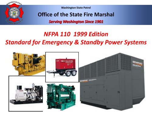
Washington State PatrolOffice of the State Fire MarshalServing Washington Since 1901<strong>NFPA</strong> <strong>110</strong> <strong>1999</strong> <strong>Edition</strong><strong>Standard</strong> <strong>for</strong> <strong>Emergency</strong> & <strong>Standby</strong> <strong>Power</strong> Systems
Level 1 EPSS• 2-2.4.1* Level 1 defines the most stringentequipment per<strong>for</strong>mance <strong>for</strong> applicationswhere failure of the equipment to per<strong>for</strong>mcould result in loss of human life or seriousinjuries. All Level 1 equipment shall bepermanently installed.
LevelMaintenance1 EPSSandOperational Testing• A-2.2.4.1 Typically, Level 1systems are intended to automaticallysupply illumination or power, or both,to critical areas and equipment in theevent of failure of the primary supplyor in the event of danger to elementsof a system intended to supply,distribute, and control power andillumination essential <strong>for</strong> safety tohuman life.• Level 1 systems generally are installedin places of assembly where artificialillumination is required <strong>for</strong> safe exitingand <strong>for</strong> panic control in buildingssubject to occupancy by largenumbers of people.
Level 1 EPSS• A-2.2.4.1 (cont’d)• <strong>Emergency</strong> systems can also providepower <strong>for</strong> such functions as ventilationwhen essential to maintain life, firedetection and alarm systems,elevators, fire pumps, public safetycommunication systems, industrialprocesses where current interruptionwould produce serious life safety orhealth hazards, and similar functions.(See <strong>NFPA</strong> 101©, Life Safety Code©, andChapter 3, Electrical Systems, of <strong>NFPA</strong> 99,<strong>Standard</strong> <strong>for</strong> Health Care Facilities)
Level 2 EPSS• 2-2.4.2 Level 2 definesequipment per<strong>for</strong>mancerequirements <strong>for</strong> applicationswhere failure of the EPSS toper<strong>for</strong>m is less critical to humanlife and safety and where it isexpected that the authorityhaving jurisdiction will exerciseits option to allow a higherdegree of flexibility thanprovided by Level l. All level 2equipment shall be permanentlyinstalled.
Type• 2-2.2 Type defines the maximum time, in seconds, thatthe EPSS will permit the load terminals of the transferswitch to be without acceptable electrical power. Table 2-2.2 provides the types defined by this standard.• Table 2-2.2 Types of EPSSs===============================================• Type U Basically uninterruptible UPS systems• Type 10 10 seconds• Type 60 60 seconds• Type 120 120 seconds• Type M Manual stationary or non-automatic – notimelimit================================================
Class• 2-2.3 Class defines the minimum time, in hours, <strong>for</strong> whichthe EPSS is designed to operate at its rated load without beingrefueled.• Table 2-2.3 Classification of EPSSs===================================================• Class 0.083 0.083 hours (5 minutes)• Class 0.25 0.25 hours (15 minutes)• Class 2 2 hours• Class 6 6 hours• Class 48 48 hours• Class X Other time in hours as requiredby the application, code, or user====================================================
Routine Maintenance andOperational Testing
Routine Maintenance• 6-1.1* The routine maintenance and operationaltesting program shall be based on the manufacturer’srecommendations, instruction manuals, and theminimum standards of this chapter and the authorityhaving jurisdiction.• 6-1.2 Consideration shall be given to temporarilyproviding a portable or alternative source whenever theemergency generator is out of service.
Manuals, Special Tools andSpare Parts• 6-2.1 At least two sets of instructionmanuals <strong>for</strong> all major components ofthe EPSS shall be supplied by themanufacturer(s) of the EPSS and shallcontain the following:• (a) A detailed explanation of the operation of the system• (b) Instructions <strong>for</strong> routine maintenance• (c) Detailed instructions <strong>for</strong> the repair of the EPS and other majorcomponents of the EPSS• (d) An illustrated parts list and part numbers• (e) Illustrated and schematic drawings of electrical wiring systems,including operating and safety devices, control panels,instrumentation, and annunciators
Manuals Special Tools and Spare Parts(Continued)• 6-2.2 For Level 1 systems, one set of instructionmanuals shall be kept in a secure location near theequipment. The other set shall be kept in a differentsecure location.• 6-2.3 Special tools and testing devices required <strong>for</strong>routine maintenance shall be available <strong>for</strong> use whenneeded.• 6-2.4 Replacement <strong>for</strong> parts identified by experienceas high mortality items shall be maintained in a securelocation(s) on the premises. Consideration shall begiven to stocking spare parts as recommended by themanufacturer.
Maintenance andOperational Testing• 6.3.1* The EPSS shall be maintained to ensure to areasonable degree that the system is capable ofsupplying serviced within the time specified <strong>for</strong> thetype and <strong>for</strong> the time duration specified <strong>for</strong> theclass.• 6-3.2 A routine maintenance and operationaltesting program shall be initiated immediately afterthe EPSS has passed acceptance tests or aftercompletion of repairs that impact the operationalreliability of the system.
Records• 6-3.3 A written schedule <strong>for</strong> routine maintenance andoperational testing of the EPSS shall be established.• 6-3.4 A written record of EPSS inspections, tests,exercising, operation, and repairs shall be maintained onthe premises. The written record shall include thefollowing:• (a) The date of the maintenance report• (b) Identification of servicing personnel• (c) Notation of any unsatisfactory condition and thecorrective action taken, including parts replaced• (d) Testing of any repair <strong>for</strong> the appropriate time asrecommended by the manufacturer
Transfer Switches andBatteries• 6-3.5 Transfer switches shall be subjected to a maintenanceprogram including connections, inspection or testing <strong>for</strong>evidence of overheating and excessive contact erosion,removal of dust and dirt, and replacement of contacts whenrequired.• 6-3.6* Storage batteries, including electrolyte levels, used inconnection with Level 1 and Level 2 systems shall beinspected at intervals of not more than 7 days and shall bemaintained in full compliance with manufacturer’sspecifications. Defective batteries shall be repaired orreplaced immediately upon discovery of defects.
Operational Inspection & Testing• 6-4.1 Level 1 and Level 2 EPSSs, includingall appurtenant components, shall beinspected weekly and shall be exercisedunder load at least monthly.• 6-4.2 Generator sets in Level 1 and Level 2service shall be exercised at least monthly<strong>for</strong> a minimum of 30 minutes using one of thefollowing methods:• (a) Under operating temperature conditionsor at not less than 30 percent of the EPSnameplate rating.• (b) Loading that maintains the minimumexhaust gas temperatures as recommendedby the manufacturer• The date and time of day <strong>for</strong> required testingshall be decided by the owner, based onfacility operations.
Operational Inspection & Testing• 6-4.2.1 Equivalent loads used <strong>for</strong> testingshall be automatically replaced withemergency loads in case of failure of theprimary source.• 6-4.2.2 Diesel-powered EPS installationsthat do not meet the requirements of 6-4.2shall be exercised monthly with theavailable EPSS load and exercisedannually with supplemental loads at 25 %of nameplate rating <strong>for</strong> 30 minutes,followed by 50 % of nameplate rating <strong>for</strong>30 minutes, followed by 75 % of nameplaterating <strong>for</strong> 60 minutes, <strong>for</strong> a total of 2continuous hours.
Load Tests6-4.3 Load tests of generator sets shall includecomplete cold starts.6-4.4 Time delays shall be set as follows:(a) Time delay on start: l second minimum• Exception: Gas turbine cycle: 0.5 second minimum(b) Time delay on transfer to emergency: nominimumrequired(c) Time delay on restoration to normal: 5 minutes(d) Time delay on shutdown: 5 minutes minimum
Transfer Switch6-4.5 Level 1 and Level 2 transfer switchesshall be operated monthly. The monthly testof a transfer switch shall consist ofelectrically operating the transfer switchfrom the standard position to the alternateposition and then return to the standardposition.• 6-4.6* EPSS circuit breakers <strong>for</strong> Level 1system usage, including main and feedbreakers between the EPS and the transferswitch load terminals, shall be exercisedannually with the EPS in the off position.– Exception: Medium and high-voltage circuitbreakers <strong>for</strong> Level 1 system usage shall beexercised every six months and tested undersimulated overload conditions every two years.
Oversight• 6-4.7 The routinemaintenance andoperational testingprogram shall beoverseen by a properlyinstructed individual.
Operational Inspection & Testing• A-6-2 Where adequately securedfrom public access, it is desirable tolocate instruction manual, specialtools and testing devices, and spareparts in the room in which theemergency power supply is located.The articles should be mounted at aconvenient location on a wall andshould be enclosed in a metal orother suitable cabinet. The cabinetshould accommodate the instructionmanual on the inside of the door.
Maintenance• A-6-3.1 The suggested maintenanceprocedure and frequency should follow thoserecommended by the manufacturer. I theabsence of such recommendations, the FiguresA-6-3.1 (a) and (b) indicate alternate suggestedprocedures.• A- 6-3.6 Maintenance of batteries shouldinclude checking and recording the value of thespecific gravity.• A- 6-4.6 Circuit breakers should be testedunder simulated overload conditions every 2years.
Questions and Answers