ELECTRICAL SOLUTIONS WIRING DUCT
ELECTRICAL SOLUTIONS WIRING DUCT
ELECTRICAL SOLUTIONS WIRING DUCT

You also want an ePaper? Increase the reach of your titles
YUMPU automatically turns print PDFs into web optimized ePapers that Google loves.
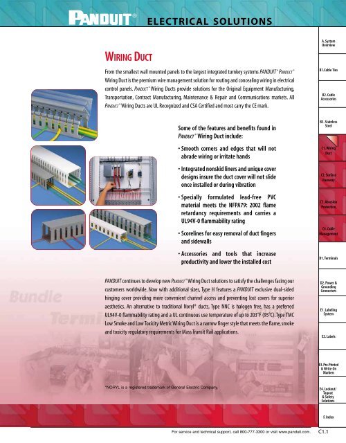
<strong>ELECTRICAL</strong> <strong>SOLUTIONS</strong><strong>WIRING</strong> <strong>DUCT</strong>From the smallest wall mounted panels to the largest integrated turnkey systems PANDUIT ® PAN<strong>DUCT</strong> ®Wiring Duct is the premium wire management solution for routing and concealing wiring in electricalcontrol panels. PAN<strong>DUCT</strong> ® Wiring Ducts provide solutions for the Original Equipment Manufacturing,Transportation, Contract Manufacturing, Maintenance & Repair and Communications markets. AllPAN<strong>DUCT</strong> ® Wiring Ducts are UL Recognized and CSA Certified and most carry the CE mark.A. SystemOverviewB1.Cable TiesB2. CableAccessoriesSome of the features and benefits found inPAN<strong>DUCT</strong> ® Wiring Duct include:• Smooth corners and edges that will notabrade wiring or irritate hands• Integrated nonskid liners and unique coverdesigns insure the duct cover will not slideonce installed or during vibration• Specially formulated lead-free PVCmaterial meets the NFPA79: 2002 flameretardancy requirements and carries aUL94V-0 flammability rating• Scorelines for easy removal of duct fingersand sidewalls• Accessories and tools that increaseproductivity and lower the installed costB3. StainlessSteelC1. WiringDuctC2. SurfaceRacewayC3. AbrasionProtectionC4. CableManagementD1. TerminalsPANDUIT continues to develop new PAN<strong>DUCT</strong> ® Wiring Duct solutions to satisfy the challenges facing ourcustomers worldwide. Now with additional sizes, Type H features a PANDUIT exclusive dual-sidedhinging cover providing more convenient channel access and preventing lost covers for superioraesthetics. An alternative to traditional Noryl* ducts, Type NNC is halogen free, has a preferredUL94V-0 flammability rating and a UL continuous use temperature of up to 203°F (95°C). Type TMCLow Smoke and Low Toxicity Metric Wiring Duct is a narrow finger style that meets the flame, smokeand toxicity regulatory requirements for Mass Transit Rail applications.D2. Power &GroundingConnectorsE1. LabelingSystemE2. LabelsE3. Pre-Printed& Write-OnMarkers*NORYL is a registered trademark of General Electric Company.E4. Lockout/Tagout& SafetySolutionsF. IndexFor service and technical support, call 800-777-3300 or visit www.panduit.com.C1.1
<strong>ELECTRICAL</strong> <strong>SOLUTIONS</strong>A. SystemOverviewWiring Duct for Control Panel ApplicationsB1.Cable Ties2B2. CableAccessoriesB3. StainlessSteelC1. WiringDuctC2. SurfaceRaceway4C3. AbrasionProtectionC4. CableManagement1D1. TerminalsD2. Power &GroundingConnectorsE1. LabelingSystemA53E2. LabelsE3. Pre-Printed& Write-OnMarkersE4. Lockout/Tagout& SafetySolutionsAFor information on FL Wiring Duct and other PAN<strong>DUCT</strong> ® Accessories (pages C1.24-C1.31)F. IndexC1.2
<strong>ELECTRICAL</strong> <strong>SOLUTIONS</strong>Wiring Duct for Control Panel Applications (continued)A. SystemOverviewB1.Cable Ties1PAN<strong>DUCT</strong> ® Type H Hinged Cover Wiring Duct(pages C1.4 – C1.5)B2. CableAccessoriesB3. StainlessSteelC1. WiringDuct2PAN<strong>DUCT</strong> ® Type F Narrow Slot Wiring Duct(pages C1.8 – C1.9)C2. SurfaceRacewayC3. AbrasionProtection3PAN<strong>DUCT</strong> ® Type G Wide Slot Wiring Duct(pages C1.6 – C1.7)C4. CableManagementD1. TerminalsD2. Power &GroundingConnectors4PAN<strong>DUCT</strong> ® Type MC Metric Wiring Duct(pages C1.12 – C1.13)E1. LabelingSystemE2. LabelsE3. Pre-Printed& Write-OnMarkers5PAN<strong>DUCT</strong> ® Type D Flush Cover Round HoleWiring Duct (pages C1.10 – C1.11)E4. Lockout/Tagout& SafetySolutionsF. IndexFor service and technical support, call 800-777-3300 or visit www.panduit.com.C1.3
<strong>ELECTRICAL</strong> <strong>SOLUTIONS</strong>A. SystemOverviewB1.Cable TiesB2. CableAccessoriesB3. StainlessSteelFeatures and Benefits – PAN<strong>DUCT</strong> ® Type H – Hinged Cover Wiring DuctAvailable in eight sizes from 1.5" x 2" up to 4" x 4" in Light Gray, Black and White colors.Dual-sided hinge coveropens up to 100° from eithersidewall of duct for up to 20%faster wiring changesCover retention flangeenables simple “push-on”installation saving timeand hassleCover removal rib eases cover openingfor quick channel access duringwiring changesC1. WiringDuctC2. SurfaceRacewayRobust channelprofile withstands aside impact force upto two times greaterthan conventionalwiring ductC3. AbrasionProtectionUpper and lower scoreline allows easy fingers andsidewall section removal saving installation timeC4. CableManagementSave Time and Material Replacement CostsD1. TerminalsD2. Power &GroundingConnectorsE1. LabelingSystemConventional MethodWith Hinged Cover Wiring DuctE2. Labels■By avoiding the time and hassle in removing and replacing covers, simple wiring changes can be made up to 20% fastercompared to conventional wiring duct installations*E3. Pre-Printed& Write-OnMarkersAvoid Cover Replacement Costs■■Covers represent 20% of the cost of the wiringduct purchaseMisplaced covers are a common occurrence afteryears of use% of Wiring Duct CostBaseCoverE4. Lockout/Tagout& SafetySolutions■Not needing to remove covers during maintenanceensures better aesthetics and safety and avoidsthe cost to replace lost covers.F. Index0%20% 40% 60% 80% 100%*Based on mock panel installations of Type H Hinged Cover Wiring Duct and other commonly available wiring ducts adding a single component with four wires.C1.4Order number of pieces required, in multiples of Standard Package Quantity.Prime items appear in BOLD.
<strong>ELECTRICAL</strong> <strong>SOLUTIONS</strong>PAN<strong>DUCT</strong> ® Type H – Hinged Cover Wiring DuctA. SystemOverview• Material: Lead-free PVC• UL Recognized continuous use temperature: 122°F (50°C)• UL94 Flammability Rating of V-0• Conforms with NFPA 79-2002 section 14.3.1 requirement for flameretardant material• Provided with mounting holesB1.Cable TiesHBase &Cover Std. Std.BaseDuct Size W x H Slot Width Cover Part Length Pkg. Ctn.Part Number In. mm In. mm Number (ft) Qty Qty.H1.5X2LG6 1.75 x 1.98 44.5 x 50.3 .31 7.9 HC1.5LG6 6 6 120H1.5X3LG6 1.75 x 3.06 44.5 x 77.7 .31 7.9 HC1.5LG6 6 6 120H2X2LG6 2.17 x 1.98 55.1 x 50.3 .31 7.9 HC2LG6 6 6 120H2X3LG6 2.17 x 3.06 55.1 x 77.7 .31 7.9 HC2LG6 6 6 60H2X4LG6 2.17 X 4.10 55.1 X 104.1 .31 7.9 HC2LG6 6 6 60H3X3LG6 3.25 x 3.06 82.6 x 77.7 .31 7.9 HC3LG6 6 6 60H3X4LG6 3.25 x 4.10 82.6 x 104.1 .31 7.9 HC3LG6 6 6 60H4X4LG6 4.25 x 4.10 108.0 x 104.1 .31 7.9 HC4LG6 6 6 60B2. CableAccessoriesB3. StainlessSteelC1. WiringDuctWPAN<strong>DUCT</strong> ® Type HS – Hinged Cover Solid Wall RacewayC2. SurfaceRaceway• Material: Lead-free PVC• UL Recognized continuous use temperature: 122°F (50°C)• UL94 Flammability Rating of V-0• Supplied without mounting holesC3. AbrasionProtectionEase of Installation and AccessBase &Cover Std. Std.BaseDuct Size (W x H)Cover Length Pkg. Ctn.Part NumberIn.mm Part Number (ft) Qty. Qty.HS1.5X2LG6NM 1.75 x 1.98 44.5 x 50.3 HC1.5LG6 6 6 120HS1.5X3LG6NM 1.75 x 3.06 44.5 x 77.7 HC1.5LG6 6 6 60HS2X2LG6NM 2.17 x 1.98 55.1 x 50.3 HC2LG6 6 6 120HS2X3LG6NM 2.17 x 3.06 55.1 x 77.7 HC2LG6 6 6 60HS2X4LG6NM 2.17 x 4.10 55.1 x 104.1 HC2LG6 6 6 60HS3X3LG6NM 3.25 x 3.06 82.6 x 77.7 HC3LG6 6 6 60HS3X4LG6NM 3.25 x 4.10 82.6 x 104.1 HC3LG6 6 6 60HS4X4LG6NM 4.25 x 4.10 108.0 x 104.1 HC4LG6 6 6 60Part Number shown for LG (Light Gray). For BL (Black) and WH (White) colors see Color Selection Guide,page C1.43.Base and cover sold separately.Push-On Cover/Dual Sided Hinging Cover■■Cover retention flanges guide duct fingers into cover for simplepush-on cover installationCover can hinge open to 100° from either sidewall to allow fullchannel accessC4. CableManagementD1. TerminalsD2. Power &GroundingConnectorsE1. LabelingSystemE2. LabelsRobust Profile with Superior Cover Performance■■■Covers fully engages fingers limiting sidewall flex for greaterrigidity and durability*Cover retention strength in vertical applications is up to2 times greater than conventional wiring ducts**Up to 2 times the side impact force is required to disengagethe cover compared to conventional wiring ducts****Based on test and measurements comparing Type H Hinged Cover Wiring Duct and other commonly available wiring ducts.For service and technical support, call 800-777-3300 or visit www.panduit.com.E3. Pre-Printed& Write-OnMarkersE4. Lockout/Tagout& SafetySolutionsF. IndexC1.5
<strong>ELECTRICAL</strong> <strong>SOLUTIONS</strong>A. SystemOverviewB1.Cable TiesFeatures and Benefits – PAN<strong>DUCT</strong> ® Type G – Wide Slot Wiring DuctAvailable in 36 sizes from .5" x .5" up to 6" x 4" in a variety of colors.B2. CableAccessoriesExclusive PANDUIT smoothrounded edges preventswiring abrasionNon-slip cover linerprevents cover slideFlush cover designprovides a neat andfinished appearanceB3. StainlessSteelC1. WiringDuctC2. SurfaceRacewayWide finger/slotdesignprovides greaterrigidity and allowsuse with a widerange of wire andbundle sizesC3. AbrasionProtectionC4. CableManagementSpecially formulatedlead-free PVC materialUpper and lower scorelines allowseasy fingers and sidewall sectionremoval saving installation timeRestricted slot designretains wires, eliminatinghassle and saving timeD1. TerminalsD2. Power &GroundingConnectorsE1. LabelingSystemPAN<strong>DUCT</strong> ® Wire Retainers for Type GWiring DuctContain wiring when duct cover isopened. Wire retainers snap easilybetween duct fingers.See page C1.26.PAN<strong>DUCT</strong> ® Divider WallCreate separate wiring channelswithin the wiring duct base. Availablein solid or slotted wall styles.See page C1.24.E2. LabelsE3. Pre-Printed& Write-OnMarkersPAN<strong>DUCT</strong> ® Installation ToolsWide selection of hand tools forcutting and installing wiring duct.See page C1.31.PAN<strong>DUCT</strong> ® Nylon RivetsFast, lowest cost mounting method.See page C1.31.E4. Lockout/Tagout& SafetySolutionsF. IndexC1.6Order number of pieces required, in multiples of Standard Package Quantity.Prime items appear in BOLD.
<strong>ELECTRICAL</strong> <strong>SOLUTIONS</strong>• Wide slot/finger design provides greater sidewall rigidity and canbe used with a wide range of wire bundle sizes• Material: Lead-free PVC• UL Recognized continuous use temperature: 122°F (50°C)• UL94 Flammability Rating of V-0HWPAN<strong>DUCT</strong> ® Type G – Wide Slot Wiring DuctBasePart Number• Conforms with NFPA 79-2002 section 14.3.1 requirement for flameretardant material• Provided with mounting holesDuct Size (W x H) Slot Width Cover PartIn. mm In. mm NumberBase &CoverLength(ft)Std.Pkg.Qty.Std.Ctn.Qty.G.5X.5LG6 .69 x .60 17.5 x 15.2 .38 9.7 C.5LG6 6 6 120G.5X1LG6 .69 x 1.06 17.5 x 26.9 .31 7.9 C.5LG6 6 6 120G.5X2LG6 .69 x 2.03 17.5 x 51.6 .31 7.9 C.5LG6 6 6 120G.5X4LG6 .69 x 4.10 17.5 x 104.1 .31 7.9 C.5LG6 6 6 60G.75X.75LG6 .93 x .82 23.6 x 20.8 .31 7.9 C.75LG6 6 6 120G.75X1LG6 .93 x 1.06 23.6 x 26.9 .31 7.9 C.75LG6 6 6 120G.75X1.5LG6 .93 x 1.57 23.6 x 39.9 .31 7.9 C.75LG6 6 6 120G.75X2LG6 .93 x 2.03 23.6 x 51.6 .31 7.9 C.75LG6 6 6 120G1X1LG6 1.26 x 1.12 32.0 x 28.4 .31 7.9 C1LG6 6 6 120G1X1.5LG6 1.26 x 1.62 32.0 x 41.1 .31 7.9 C1LG6 6 6 120G1X2LG6 1.26 x 2.12 32.0 x 53.8 .31 7.9 C1LG6 6 6 120G1X3LG6 1.26 x 3.12 32.0 x 79.2 .31 7.9 C1LG6 6 6 120G1X4LG6 1.26 x 4.10 32.0 x 104.1 .31 7.9 C1LG6 6 6 60G1.5X1LG6 1.75 x 1.12 44.5 x 28.4 .31 7.9 C1.5LG6 6 6 120G1.5X1.5LG6 1.75 x 1.62 44.5 x 41.1 .31 7.9 C1.5LG6 6 6 120G1.5X2LG6 1.75 x 2.12 44.5 x 53.8 .31 7.9 C1.5LG6 6 6 120G1.5X3LG6 1.75 x 3.12 44.5 x 79.2 .31 7.9 C1.5LG6 6 6 120G1.5X4LG6 1.75 x 4.10 44.5 x 104.1 .31 7.9 C1.5LG6 6 6 60G2X1LG6 2.25 x 1.12 57.2 x 28.4 .31 7.9 C2LG6 6 6 120G2X1.5LG6 2.25 x 1.62 57.2 x 41.1 .31 7.9 C2LG6 6 6 120G2X2LG6 2.25 x 2.12 57.2 x 53.8 .31 7.9 C2LG6 6 6 120G2X3LG6 2.25 x 3.12 57.2 x 79.2 .31 7.9 C2LG6 6 6 60G2X4LG6 2.25 x 4.10 57.2 x 104.1 .31 7.9 C2LG6 6 6 60G2X5LG6 2.25 x 5.10 57.2 x 129.5 .38 9.7 C2LG6 6 6 60G2.5X3LG6 2.75 x 3.12 69.9 x 79.2 .31 7.9 C2.5LG6 6 6 120G3X1LG6 3.25 x 1.12 82.6 x 28.4 .31 7.9 C3LG6 6 6 120G3X2LG6 3.25 x 2.12 82.6 x 53.8 .31 7.9 C3LG6 6 6 120G3X3LG6 3.25 x 3.12 82.6 x 79.2 .31 7.9 C3LG6 6 6 60G3X4LG6 3.25 x 4.10 82.6 x 104.1 .31 7.9 C3LG6 6 6 60G3X5LG6 3.25 x 5.10 82.6 x 129.5 .38 9.7 C3LG6 6 6 60G4X1.5LG6 4.25 x 1.62 108.0 x 41.1 .31 7.9 C4LG6 6 6 120G4X2LG6 4.25 x 2.12 108.0 x 53.8 .31 7.9 C4LG6 6 6 60G4X3LG6 4.25 x 3.12 108.0 x 79.2 .31 7.9 C4LG6 6 6 60G4X4LG6 4.25 x 4.10 108.0 x 104.1 .31 7.9 C4LG6 6 6 60G4X5LG6 4.25 x 5.10 108.0 x 129.5 .38 9.7 C4LG6 6 6 60G6X4LG6 6.25 x 4.15 158.8 x 105.4 .31 7.9 C6LG6 6 6 60Part Number shown for LG (Light Gray). For other color availability see Color Selection Guide, page C1.43.Base and cover sold separately.A. SystemOverviewB1.Cable TiesB2. CableAccessoriesB3. StainlessSteelC1. WiringDuctC2. SurfaceRacewayC3. AbrasionProtectionC4. CableManagementD1. TerminalsD2. Power &GroundingConnectorsE1. LabelingSystemE2. LabelsE3. Pre-Printed& Write-OnMarkersE4. Lockout/Tagout& SafetySolutionsF. IndexFor service and technical support, call 800-777-3300 or visit www.panduit.com.C1.7
<strong>ELECTRICAL</strong> <strong>SOLUTIONS</strong>A. SystemOverviewB1.Cable TiesFeatures and Benefits – PAN<strong>DUCT</strong> ® Type F – Narrow Slot Wiring DuctAvailable in 29 sizes from .5" x .5" up to 4" x 5" in a variety of colors.B2. CableAccessoriesB3. StainlessSteelExclusive PANDUITsmooth rounded edgesprevents wiring abrasionDouble restricted slot designretains wires, eliminating hassleand saving timeNon-slip cover linerprevents cover slideC1. WiringDuctC2. SurfaceRacewayC3. AbrasionProtectionSpecially formulatedlead-free PVC materialNarrow finger/slot designclosely matches the spacingof high-density componentsFlush cover designprovides a neatappearanceC4. CableManagementUpper and lower scorelines allows easy fingersand sidewall section removal saving installation timeD1. TerminalsD2. Power &GroundingConnectorsE1. LabelingSystemPAN<strong>DUCT</strong> ® Wire Retainers forType F Wiring DuctContain wiring when duct cover isopened. Wire retainers snap easilybetween duct fingers.See page C1.27.PAN<strong>DUCT</strong> ® Divider WallCreate separate wiring channelswithin the wiring duct base. Availablein solid or slotted wall styles.See page C1.24.E2. LabelsE3. Pre-Printed& Write-OnMarkersPAN<strong>DUCT</strong> ® Installation ToolsWide selection of hand tools forcutting and installing wiring duct.See page C1.31.PAN<strong>DUCT</strong> ® Nylon RivetsFast, lowest cost mounting method.See page C1.31.E4. Lockout/Tagout& SafetySolutionsF. IndexC1.8Order number of pieces required, in multiples of Standard Package Quantity.Prime items appear in BOLD.
<strong>ELECTRICAL</strong> <strong>SOLUTIONS</strong>• Narrow slot/finger design provides more slots to fit the spacing ofhigh-density terminal blocks and other hardware• Material: Lead-free PVC• UL Recognized continuous use temperature: 122°F (50°C)• UL94 Flammability Rating of V-0HWPAN<strong>DUCT</strong> ® Type F – Narrow Slot Wiring Duct• Conforms with NFPA 79-2002 section 14.3.1 requirement for flameretardant material• Provided with mounting holesBase &Cover Cover Std. Std.BaseDuct Size (W x H) Slot Width Part Length Pkg. Ctn.Part Number In. mm In. mm Number (ft) Qty. Qty.F.5X.5LG6 .69 x .60 17.5 x 15.2 .20 5.0 C.5LG6 6 6 120F.5X1LG6 .69 x 1.06 17.5 x 26.9 .20 5.0 C.5LG6 6 6 120F.75X.75LG6 .93 x .82 23.6 x 20.8 .20 5.0 C.75LG6 6 6 120F.75X1.5LG6 .93 x 1.57 23.6 x 39.9 .20 5.0 C.75LG6 6 6 120F1X1LG6 1.26 x 1.12 32.0 x 28.4 .20 5.0 C1LG6 6 6 120F1X1.5LG6 1.26 x 1.62 32.0 x 41.1 .20 5.0 C1LG6 6 6 120F1X2LG6 1.26 x 2.12 32.0 x 53.8 .20 5.0 C1LG6 6 6 120F1X3LG6 1.26 x 3.12 32.0 x 79.2 .20 5.0 C1LG6 6 6 120F1X4LG6 1.26 x 4.10 32.0 x 104.1 .20 5.0 C1LG6 6 6 60F1.5X1LG6 1.75 x 1.12 44.5 x 28.4 .20 5.0 C1.5LG6 6 6 120F1.5X1.5LG6 1.75 x 1.62 44.5 x 41.1 .20 5.0 C1.5LG6 6 6 120F1.5X2LG6 1.75 x 2.12 44.5 x 53.8 .20 5.0 C1.5LG6 6 6 120F1.5X3LG6 1.75 x 3.12 44.5 x 79.2 .20 5.0 C1.5LG6 6 6 120F1.5X4LG6 1.75 x 4.10 44.5 x 104.1 .20 5.0 C1.5LG6 6 6 60F2X1LG6 2.25 x 1.12 57.2 x 28.4 .20 5.0 C2LG6 6 6 120F2X1.5LG6 2.25 x 1.62 57.2 x 41.1 .20 5.0 C2LG6 6 6 120F2X2LG6 2.25 x 2.12 57.2 x 53.8 .20 5.0 C2LG6 6 6 120F2X3LG6 2.25 x 3.12 57.2 x 79.2 .20 5.0 C2LG6 6 6 60F2X4LG6 2.25 x 4.10 57.2 x 104.1 .20 5.0 C2LG6 6 6 60F2X5LG6 2.25 x 5.10 57.2 x 129.5 .20 5.0 C2LG6 6 6 60F3X1LG6 3.25 x 1.12 82.6 x 28.4 .20 5.0 C3LG6 6 6 120F3X2LG6 3.25 x 2.12 82.6 x 53.8 .20 5.0 C3LG6 6 6 120F3X3LG6 3.25 x 3.12 82.6 x 79.2 .20 5.0 C3LG6 6 6 60F3X4LG6 3.25 x 4.10 82.6 x 104.1 .20 5.0 C3LG6 6 6 60F3X5LG6 3.25 x 5.10 82.6 x 129.5 .20 5.0 C3LG6 6 6 60F4X2LG6 4.25 x 2.12 108.0 x 53.8 .20 5.0 C4LG6 6 6 60F4X3LG6 4.25 x 3.12 108.0 x 79.2 .20 5.0 C4LG6 6 6 60F4X4LG6 4.25 x 4.10 108.0 x 104.1 .20 5.0 C4LG6 6 6 60F4X5LG6 4.25 x 5.10 108.0 x 129.5 .20 5.0 C4LG6 6 6 60Part Number shown for LG (Light Gray). For other color availability see Color Selection Guide, page C1.43.Base and cover sold separately.A. SystemOverviewB1.Cable TiesB2. CableAccessoriesB3. StainlessSteelC1. WiringDuctC2. SurfaceRacewayC3. AbrasionProtectionC4. CableManagementD1. TerminalsD2. Power &GroundingConnectorsE1. LabelingSystemE2. LabelsE3. Pre-Printed& Write-OnMarkersE4. Lockout/Tagout& SafetySolutionsF. IndexFor service and technical support, call 800-777-3300 or visit www.panduit.com.C1.9
<strong>ELECTRICAL</strong> <strong>SOLUTIONS</strong>A. SystemOverviewB1.Cable TiesFeatures and Benefits – PAN<strong>DUCT</strong> ® Flush Cover Type D – Round Hole Wiring DuctAvailable in 16 sizes from 1" x 2" up to 4" x 4" in a variety of colors.B2. CableAccessoriesNon-slip cover linerprevents cover slideExclusive PANDUITsmooth rounded edgesprevents wiring abrasionB3. StainlessSteelC1. WiringDuctC2. SurfaceRacewayFlush cover designprovides a neat andfinished appearanceC3. AbrasionProtectionSpeciallyformulatedlead-free PVCmaterialRound hole designretains and supports wireat variable heights toenhance wire managementBase scoreline allows easyremoval of sidewall section att-junctions and right angles savinginstallation timeC4. CableManagementD1. TerminalsD2. Power &GroundingConnectorsE1. LabelingSystemE2. LabelsPAN<strong>DUCT</strong> ® Wire Retainersfor Type D Wiring DuctContain wiring when ductcover is opened. Wire retainersmount onto walls with pressuresensitive adhesive.See page C1.26.PAN<strong>DUCT</strong> ® Divider WallCreate separate wiring channelswithin the wiring duct base. Availablein solid or slotted wall styles.See page C1.24.E3. Pre-Printed& Write-OnMarkersPAN<strong>DUCT</strong> ® Installation ToolsWide selection of hand tools forcutting and installing wiring duct.See page C1.31.PAN<strong>DUCT</strong> ® Nylon RivetsFast, lowest cost mounting method.See page C1.31.E4. Lockout/Tagout& SafetySolutionsF. IndexC1.10Order number of pieces required, in multiples of Standard Package Quantity.Prime items appear in BOLD.
<strong>ELECTRICAL</strong> <strong>SOLUTIONS</strong>A. SystemOverviewPAN<strong>DUCT</strong> ® Flush Cover Type D – Round Hole Wiring Duct• Round hole design has multiple rows of holes to retain andsupport wire at variable heights and positions• Material: Lead-free PVC• UL Recognized continuous use temperature: 122°F (50°C)• UL94 Flammability Rating of V-0HWBasePart Number• Conforms with NFPA 79-2002 section 14.3.1 requirement for flameretardant material• Provided with mounting holesDuct Size (W x H)In.mmCoverPart NumberBase &CoverLength(ft)Std.Pkg.Qty.Std.Ctn.Qty.D1X2LG6 1.26 x 2.12 32.0 x 53.8 C1LG6 6 6 120D1X3LG6 1.26 x 3.12 32.0 x 79.2 C1LG6 6 6 120D1X4LG6 1.26 x 4.10 32.0 x 104.1 C1LG6 6 6 120D1.5X2LG6 1.75 x 2.12 44.5 x 53.8 C1.5LG6 6 6 120D1.5X3LG6 1.75 x 3.12 44.5 x 79.2 C1.5LG6 6 6 120D1.5X4LG6 1.75 x 4.10 44.5 x 104.1 C1.5LG6 6 6 60D2X2LG6 2.25 x 2.12 57.2 x 53.8 C2LG6 6 6 120D2X3LG6 2.25 x 3.12 57.2 x 79.2 C2LG6 6 6 60D2X4LG6 2.25 x 4.10 57.2 x 104.1 C2LG6 6 6 60D2.5X3LG6 2.75 x 3.12 69.9 x 79.2 C2.5LG6 6 6 120D3X2LG6 3.25 x 2.12 82.6 x 53.8 C3LG6 6 6 120D3X3LG6 3.25 x 3.12 82.6 x 79.2 C3LG6 6 6 60D3X4LG6 3.25 x 4.10 82.6 x 104.1 C3LG6 6 6 60D4X2LG6 4.25 x 2.12 108.0 x 53.8 C4LG6 6 6 60D4X3LG6 4.25 x 3.12 108.0 x 79.2 C4LG6 6 6 60D4X4LG6 4.25 x 4.10 108.0 x 104.1 C4LG6 6 6 60Part Number shown for LG (Light Gray). For other color availability see Color Selection Guide, page C1.43.Base and cover sold separately.B1.Cable TiesB2. CableAccessoriesB3. StainlessSteelC1. WiringDuctC2. SurfaceRacewayC3. AbrasionProtectionC4. CableManagement.67 +- .06 TYP[16.94 +- 1.5].44 +- .02[11.2 +- 0.5]D1. TerminalsHD2. Power &GroundingConnectorsFor 2" duct height = 3 rows of holes3" duct height = 4 rows of holes4" duct height = 6 rows of holesE1. LabelingSystemE2. LabelsE3. Pre-Printed& Write-OnMarkersE4. Lockout/Tagout& SafetySolutionsF. IndexFor service and technical support, call 800-777-3300 or visit www.panduit.com.C1.11
<strong>ELECTRICAL</strong> <strong>SOLUTIONS</strong>A. SystemOverviewB1.Cable TiesFeatures and Benefits – PAN<strong>DUCT</strong> ® Type MC – Metric Narrow Slot Wiring DuctAvailable in 22 sizes from 25mm x 25mm up to 100mm x 100mm in International Gray color.B2. CableAccessoriesDouble restricted slot designretains wires, eliminating hassle andsaving timeNon-slip cover linerprevents cover slideB3. StainlessSteelNarrow finger/slot designmatches the spacing ofhigh-density componentsC1. WiringDuctC2. SurfaceRacewayFlush cover designprovides a neatfinished appearanceC3. AbrasionProtectionC4. CableManagementSpeciallyformulatedlead-free PVCmaterialUpper and lower scorelines alloweasy fingers and sidewall sectionremoval saving installation timeDIN 43 659 metric mountinghole pattern meets EuropeanrequirementsD1. TerminalsD2. Power &GroundingConnectorsE1. LabelingSystemPAN<strong>DUCT</strong> ® Wire Retainers forType MC Wiring DuctContain wiring when duct cover isopened. Wire retainers snap easilybetween duct fingers.See page C1.27.PAN<strong>DUCT</strong> ® Divider WallCreate separate wiring channelswithin the wiring duct base. Availablein solid or slotted wall styles.See page C1.24.E2. LabelsPAN<strong>DUCT</strong> ® Installation ToolsWide selection of hand tools fo rcutting and installing wiring duct.See page C1.31.PAN<strong>DUCT</strong> ® Nylon RivetsFast, lowest cost mounting method.See page C1.31.E3. Pre-Printed& Write-OnMarkersE4. Lockout/Tagout& SafetySolutionsF. IndexC1.12Order number of pieces required, in multiples of Standard Package Quantity.Prime items appear in BOLD.
<strong>ELECTRICAL</strong> <strong>SOLUTIONS</strong>PAN<strong>DUCT</strong> ® Type MC – Metric Narrow Slot Wiring DuctA. SystemOverview• CE compliant and metric sizing for control panels intended forEuropean applications• Material: Lead-free PVC• UL Recognized continuous use temperature: 122°F (50°C)• UL94 Flammability Rating of V-0• Conforms with NFPA 79-2002 section 14.3.1 requirement for flameretardant material• Provided with DIN 43 659 mounting holes• Duct and cover packaged together in 2 meter lengthsB1.Cable TiesB2. CableAccessoriesHWStd.Replacement Base & Cover Pkg.Base & Cover Duct Size (W x H) Slot Width Cover Length Qty.Part Number mm In. In. mm Part Number (M) (M)MC25X25IG2 24.6 x 23.6 .97 x .93 .20 5.0 C25IG2 2 20MC25X37IG2 24.6 x 35.8 .97 x 1.41 .20 5.0 C25IG2 2 20MC25X50IG2 24.6 x 47.8 .97 x 1.88 .20 5.0 C25IG2 2 20MC25X62IG2 24.6 x 59.7 .97 x 2.35 .20 5.0 C25IG2 2 20MC25X75IG2 24.6 x 72.4 .97 x 2.85 .20 5.0 C25IG2 2 20MC37X37IG2 37.1 x 35.8 1.46 x 1.41 .20 5.0 C37IG2 2 20MC37X50IG2 37.1 x 47.8 1.46 x 1.88 .20 5.0 C37IG2 2 20MC37X62IG2 37.1 x 59.7 1.46 x 2.35 .20 5.0 C37IG2 2 20MC37X75IG2 37.1 x 72.4 1.46 x 2.85 .20 5.0 C37IG2 2 20MC50X50IG2 49.5 x 47.8 1.95 x 1.89 .20 5.0 C50IG2 2 20MC50X75IG2 49.5 x 72.4 1.95 x 2.85 .20 5.0 C50IG2 2 10MC50X100IG2 49.5 x 97.8 1.95 x 3.85 .20 5.0 C50IG2 2 10MC62X37IG2 62.0 x 35.8 2.44 x 1.41 .20 5.0 C62IG2 2 20MC62X62IG2 62.0 x 59.7 2.44 x 2.35 .20 5.0 C62IG2 2 20MC75X50IG2 74.7 x 48.0 2.94 x 1.89 .20 5.0 C75IG2 2 20MC75X62IG2 74.7 x 59.7 2.94 x 2.35 .20 5.0 C75IG2 2 20MC75X75IG2 74.7 x 72.4 2.94 x 2.85 .20 5.0 C75IG2 2 10MC75X100IG2 74.7 x 97.8 2.94 x 3.85 .20 5.0 C75IG2 2 10MC100X50IG2 99.6 x 48.0 3.92 x 1.89 .20 5.0 C100IG2 2 10MC100X62IG2 99.6 x 59.7 3.92 x 2.35 .20 5.0 C100IG2 2 10MC100X75IG2 99.6 x 72.4 3.92 x 2.85 .20 5.0 C100IG2 2 10MC100X100IG2 99.6 x 97.8 3.92 x 3.85 .20 5.0 C100IG2 2 10Available in IG (International Gray) only.Base and cover sold together.B3. StainlessSteelC1. WiringDuctC2. SurfaceRacewayC3. AbrasionProtectionC4. CableManagementD1. TerminalsD2. Power &GroundingConnectorsE1. LabelingSystemE2. LabelsE3. Pre-Printed& Write-OnMarkersE4. Lockout/Tagout& SafetySolutionsF. IndexFor service and technical support, call 800-777-3300 or visit www.panduit.com.C1.13
<strong>ELECTRICAL</strong> <strong>SOLUTIONS</strong>A. SystemOverviewB1.Cable TiesFeatures and Benefits – PAN<strong>DUCT</strong> ® Type FS – Solid Wall RacewayAvailable in 27 sizes from .5" x .5" up to 6" x 4" in a variety of colors.B2. CableAccessoriesB3. StainlessSteelSpeciallyformulatedlead-free PVCmaterialNon-slip cover linerprevents cover slideC1. WiringDuctC2. SurfaceRacewayC3. AbrasionProtectionFlush cover designprovides a neat andfinished appearanceC4. CableManagementBase scoreline allows easyremoval of sidewall sectionssaving installation timeD1. TerminalsD2. Power &GroundingConnectorsE1. LabelingSystemPAN<strong>DUCT</strong> ® Wire Retainers forType FS Solid Wall RacewayContain wiring when duct coveris opened. Wire retainers mountsonto walls with pressuresensitive adhesive.See page C1.26.PAN<strong>DUCT</strong> ® Divider WallCreate separate wiring channelswithin the wiring duct base. Availablein solid or slotted wall styles.See page C1.24.E2. LabelsE3. Pre-Printed& Write-OnMarkersPAN<strong>DUCT</strong> ® Installation ToolsWide selection of hand tools forcutting and installing wiring duct.See page C1.31.PAN<strong>DUCT</strong> ® Nylon RivetsFast, lowest cost mounting method.See page C1.31.E4. Lockout/Tagout& SafetySolutionsF. IndexC1.14Order number of pieces required, in multiples of Standard Package Quantity.Prime items appear in BOLD.
<strong>ELECTRICAL</strong> <strong>SOLUTIONS</strong>A. SystemOverviewPAN<strong>DUCT</strong> ® Type FS – Solid Wall Raceway• Solid wall design fully encloses cables providing maximumprotection and aesthetics• Material: Lead-free PVC• UL Recognized continuous use temperature: 122°F (50°C)• UL94 Flammability Rating of V-0• Supplied without mounting holesB1.Cable TiesHW>>>>>>>>>>>>>>>>>>>Std. Std.Base PartDuct Size (W x H) Cover Part Base & Cover Pkg. Ctn.NumberIn.mmNumber Length (ft) Qty. Qty.FS.5X.5LG6NM .69 x .60 17.5 x 15.2 C.5LG6 6 6 120FS.5X1LG6NM .69 x 1.06 17.5 x 26.9 C.5LG6 6 6 120FS.75X.75LG6NM .93 x .82 23.6 x 20.8 C.75LG6 6 6 120FS1X1LG6NM 1.26 x 1.12 32.0 x 28.4 C1LG6 6 6 120FS1X1.5LG6NM 1.26 x 1.62 32.0 x 41.1 C1LG6 6 6 120FS1X2LG6NM 1.26 x 2.12 32.0 x 53.8 C1LG6 6 6 120FS1X3LG6NM 1.26 x 3.12 32.0 x 79.2 C1LG6 6 6 120FS1X4LG6NM 1.26 x 4.10 32.0 x 104.1 C1LG6 6 6 60FS1.5X1LG6NM 1.75 x 1.12 44.5 x 28.4 C1.5LG6 6 6 120FS1.5X1.5LG6NM 1.75 x 1.62 44.5 x 41.1 C1.5LG6 6 6 120FS1.5X2LG6NM 1.75 x 2.12 44.5 x 53.8 C1.5LG6 6 6 120FS1.5X3LG6NM 1.75 x 3.12 44.5 x 79.2 C1.5LG6 6 6 120FS2X1LG6NM 2.25 x 1.12 57.2 x 28.4 C2LG6 6 6 120FS2X1.5LG6NM 2.25 x 1.62 57.2 x 41.1 C2LG6 6 6 120FS2X2LG6NM 2.25 x 2.12 57.2 x 53.8 C2LG6 6 6 120FS2X3LG6NM 2.25 x 3.12 57.2 x 79.2 C2LG6 6 6 60FS2X4LG6NM 2.25 x 4.10 57.2 x 104.1 C2LG2 6 6 60FS3X1LG6NM 3.25 x 1.12 82.6 x 28.4 C3LG6 6 6 120FS3X2LG6NM 3.25 x 2.12 82.6 x 53.8 C3LG6 6 6 120FS3X3LG6NM 3.25 x 3.12 82.6 x 79.2 C3LG6 6 6 60FS3X4LG6NM 3.25 x 4.10 82.6 x 104.1 C3LG6 6 6 60FS3X5LG6NM 3.25 x 5.10 82.6 x 129.5 C3LG6 6 6 60FS4X2LG6NM 4.25 x 2.12 108.0 x 53.8 C4LG6 6 6 60FS4X3LG6NM 4.25 x 3.12 108.0 x 79.2 C4LG6 6 6 60FS4X4LG6NM 4.25 x 4.10 108.0 x 104.1 C4LG6 6 6 60FS4X5LG6NM 4.25 x 5.10 108.0 x 129.5 C4LG6 6 6 60FS6X4LG6NM 6.25 x 4.15 158.8 x 105.4 C6LG6 6 6 60B2. CableAccessoriesB3. StainlessSteelC1. WiringDuctC2. SurfaceRacewayC3. AbrasionProtectionC4. CableManagementD1. TerminalsD2. Power &GroundingConnectors> Indicates parts available with mounting holes. Remove NM from part number.Part Number shown for LG (Light Gray). For other color availability see Color Selection Guide, page C1.43.Base and cover sold separately.E1. LabelingSystemE2. LabelsE3. Pre-Printed& Write-OnMarkersE4. Lockout/Tagout& SafetySolutionsF. IndexFor service and technical support, call 800-777-3300 or visit www.panduit.com.C1.15
<strong>ELECTRICAL</strong> <strong>SOLUTIONS</strong>A. SystemOverviewWiring Duct for Special EnvironmentsB1.Cable TiesType NNC Halogen Free Metric Wiring DuctB2. CableAccessoriesB3. StainlessSteel• Halogen free material is nontoxic, lead-free, environmentally safe and willnot release toxic or corrosive gases that could endanger public safety ordamage sensitive electronic equipment• UL94V-0C1. WiringDuctType NE NORYL* Halogen Free Wiring DuctC2. SurfaceRacewayC3. AbrasionProtection• Halogen free material is nontoxic, lead-free, environmentally safe and willnot release toxic or corrosive gases that could endanger public safety ordamage sensitive electronic equipment• UL94V-1C4. CableManagementD1. TerminalsType TMC Low Smoke/Low Toxicity Free Wiring DuctD2. Power &GroundingConnectorsE1. LabelingSystem• Low smoke/low toxicity material emits a low level of toxic fumes and lowsmoke emissions when burned• Meets Federal Rail Administration Guidelines and NFPA 130requirements for all transit vehicles• UL94V-0E2. LabelsE3. Pre-Printed& Write-OnMarkersE4. Lockout/Tagout& SafetySolutionsThe material isself-extinguishing andhas excellent flameretardancy UL94V-0.The material doesnot release densesmoke when burned perASTM E662 test method.The material does notemit a high volume oftoxic gases when burnedper Boeing and Airbustest methods.F. IndexC1.16*NORYL is a registered trademark of General Electric Company.
<strong>ELECTRICAL</strong> <strong>SOLUTIONS</strong>A. SystemOverviewEnvironment/Material SpecificationsTypical Applicationspages C1.18 – C1.19B1.Cable TiesSemiconductorManufacturingShip BuildingNuclear Power PlantsOil PlatformsB2. CableAccessoriesB3. StainlessSteelC1. WiringDuctEnvironment/Material SpecificationsTypical Applicationspage C1.22C2. SurfaceRacewaySemiconductorManufacturingShip BuildingNuclear Power PlantsOil PlatformsC3. AbrasionProtectionC4. CableManagementEnvironment/Material SpecificationsTypical Applicationspages C1.20 – C1.21D1. TerminalsPassenger Rail CarsOther Transportation VehiclesD2. Power &GroundingConnectorsE1. LabelingSystemE2. LabelsThe material contains no fluorine,bromide or chlorine and will notemit any corrosive or toxic gaseswhen burned per IEC 60754-2test method.Material is rated for a continuous usetemperature above 75°C (167°F).E3. Pre-Printed& Write-OnMarkersE4. Lockout/Tagout& SafetySolutionsF. IndexFor service and technical support, call 800-777-3300 or visit www.panduit.com.C1.17
<strong>ELECTRICAL</strong> <strong>SOLUTIONS</strong>A. SystemOverviewB1.Cable TiesFeatures and Benefits – PAN<strong>DUCT</strong> ® Type NNC – Halogen Free Metric Wiring DuctAvailable in 14 sizes from 25mm x 25mm up to 100mm x 100mm in Light Gray and White.B2. CableAccessoriesDIN 43 659 metricmounting hole patternmeets EuropeanrequirementsNon-slip coverliner preventscover slideB3. StainlessSteelHalogen free modified PPOmaterial is environmentallysafe and will not releasecorrosive or toxic gasesC1. WiringDuctC2. SurfaceRacewayWide finger/slot designprovides greater rigidityand allows use with awide range of wire andbundle sizesFlush coverdesign provides aneat and finishedappearanceC3. AbrasionProtectionUpper and lower Scorelines allows easy finger andsidewall section removal, saving installation timeC4. CableManagementD1. TerminalsD2. Power &GroundingConnectorsPAN<strong>DUCT</strong> ® Notching ToolNotches duct sidewalls to bottomscoreline for tee and corner junctions.See page C1.31.PAN<strong>DUCT</strong> ® Type NNC Halogen FreeSolid Divider WallCreate separate wiring channelswithin the wiring duct base.See page C1.19.E1. LabelingSystemE2. LabelsE3. Pre-Printed& Write-OnMarkersPAN<strong>DUCT</strong> ® Nylon RivetInstallation ToolInstalls PAN<strong>DUCT</strong> Nylon Rivets quicklyand easily.See page C1.31.PAN<strong>DUCT</strong> ® Nylon RivetsFast, lowest cost mounting method.See page C1.31.E4. Lockout/Tagout& SafetySolutionsF. IndexC1.18Order number of pieces required, in multiples of Standard Package Quantity.Prime items appear in BOLD.
<strong>ELECTRICAL</strong> <strong>SOLUTIONS</strong>PAN<strong>DUCT</strong> ® Type NNC – Halogen Free Metric Wiring DuctA. SystemOverview• Material: Halogen free modified PPO material as verified with IEC60754-2 test method (test on gases evolved during combustion ofelectric cables)• UL Recognized continuous use temperature: 203°F (95°C)• UL94 Flammability Rating of V-0• Conforms with NFPA 79-2002 section 14.3.1 requirement for flameretardant material• Provided with DIN 43 659 mounting holes• Metric sizing and finger progression• Duct and cover packaged together in 2 meter lengthsB1.Cable TiesB2. CableAccessoriesBase and CoverPart NumberDuct Size (W x H) Slot Widthmm In. In. mmReplacementCoverPart NumberBase &CoverLength(M)Std.Ctn.Qty.(M)B3. StainlessSteelNNC25X25LG2 24.6 x 23.6 .97 x .93 .39 10.0 NC25LG2 2 20NNC25X37LG2 24.6 x 35.8 .97 x 1.41 .39 10.0 NC25LG2 2 20C1. WiringDuctNNC25X50LG2 24.6 x 47.8 .97 x 1.88 .39 10.0 NC25LG2 2 20NNC25X75LG2 24.6 x 72.4 .97 x 2.85 .39 10.0 NC25LG2 2 20WNNC37X37LG2 37.1 x 35.8 1.46 x 1.41 .39 10.0 NC37LG2 2 20NNC37X50LG2 37.1 x 47.8 1.46 x 1.88 .39 10.0 NC37LG2 2 20NNC37X75LG2 37.1 x 72.4 1.46 x 2.85 .39 10.0 NC37LG2 2 20C2. SurfaceRacewayNNC50X50LG2 49.5 x 47.8 1.95 x 1.88 .39 10.0 NC50LG2 2 20HNNC50X75LG2 49.5 x 72.4 1.95 x 2.85 .39 10.0 NC50LG2 2 10NNC50X100LG2 49.5 x 97.8 1.95 x 3.85 .39 10.0 NC50LG2 2 10NNC75X75LG2 74.7 x 72.4 2.94 x 2.85 .39 10.0 NC75LG2 2 10C3. AbrasionProtectionNNC100X50LG2 99.6 x 47.8 3.92 x 1.88 .39 10.0 NC100LG2 2 10NNC100X75LG2 99.6 x 72.4 3.92 x 2.85 .39 10.0 NC100LG2 2 10NNC100X100LG2 99.6 x 97.8 3.92 x 3.85 .39 10.0 NC100LG2 2 10C4. CableManagementAvailable in LG (Light Gray) and WH (White).Do not allow cutting, tapping or cleaning fluids that contain hydrocarbons to come in contact with Type NNC WiringDuct as it will cause stress cracking. See page C1.44 for a list of chemicals to avoid.Base and cover sold together.D1. TerminalsD2. Power &GroundingConnectorsPAN<strong>DUCT</strong> ® Type NNC Halogen Free Solid Divider Wall• NNC Solid Divider Wall can be mounted inside NNC or NE WiringDuct to create multiple channels• Material: Halogen free modified PPO• Simply install the divider wall base when mounting the duct andsnap the divider wall onto mounting base, DB-CE1. LabelingSystemPart NumberFor NominalDuct Height(mm)Length(M)Std.Pkg.Qty.Std.Ctn.Qty.NNC50DWH2 50 2 2 40NNC75DWH2 75 2 2 40Available in WH (White) color only.NOTE: Must be used with Mounting Base, DB-C (see page C1.24) which is sold separately. Install mounting basesto the duct channel, locate within 2" of each divider wall end and at least every 12" along the length.E2. LabelsE3. Pre-Printed& Write-OnMarkersNNC**DWH2E4. Lockout/Tagout& SafetySolutionsF. IndexFor service and technical support, call 800-777-3300 or visit www.panduit.com.C1.19
<strong>ELECTRICAL</strong> <strong>SOLUTIONS</strong>A. SystemOverviewB1.Cable TiesFeatures and Benefits – PAN<strong>DUCT</strong> ® Type TMC – Low Smoke/Low Toxicity Wiring DuctAvailable in seven sizes from 25mm x 37mm up to 100mm x 75mm in Beige color.B2. CableAccessoriesDouble restricted slotdesign retains wires,eliminating hassle andsaving timeB3. StainlessSteelC1. WiringDuctNon-slip coverliner preventscover slideC2. SurfaceRacewayC3. AbrasionProtectionC4. CableManagementLow smoke, lowtoxicity and lowflammability materialmeets Federal RailAdministrationguidelinesUpper and lower scorelinesallows easy fingers and sidewallsection removal saving installation timeDIN 43 659 metricmounting holepattern meetsEuropeanrequirementsNarrow finger/slot designclosely matches the spacingof high-density componentsD1. TerminalsD2. Power &GroundingConnectorsE1. LabelingSystemPAN<strong>DUCT</strong> ® Wire Retainers for TypeTMC Wiring DuctContain wiring when duct cover isopened. Wire retainers snap easilybetween duct fingers.See page C1.27.PAN<strong>DUCT</strong> ® Type TMC Low Smoke/Low Toxicity Solid Divider WallCreate separate wiring channelswithin the wiring duct base.See page C1.21.E2. LabelsPAN<strong>DUCT</strong> ® Installation ToolsWide selection of hand tools forcutting and installing wiring duct.See page C1.31.PAN<strong>DUCT</strong> ® Nylon RivetsFast, lowest cost mounting method.See page C1.31.E3. Pre-Printed& Write-OnMarkersE4. Lockout/Tagout& SafetySolutionsF. IndexC1.20Order number of pieces required, in multiples of Standard Package Quantity.Prime items appear in BOLD.
<strong>ELECTRICAL</strong> <strong>SOLUTIONS</strong>A. SystemOverviewPAN<strong>DUCT</strong> ® Type NE – NORYL* Halogen Free Wiring DuctB1.Cable Ties• Material: Halogen free NORYL*• UL Recognized continuous use temperature: 203°F (95°C)• UL94 Flammability Rating of V-1• Provided with mounting holesB2. CableAccessoriesB3. StainlessSteelC1. WiringDuctC2. SurfaceRacewayC3. AbrasionProtectionC4. CableManagementD1. TerminalsD2. Power &GroundingConnectorsE1. LabelingSystemHWBase PartNumberDuct Size W x H Slot Width Cover PartIn. mm In. mm NumberNE.5X.5WH6 .63 x .56 16.0 x 14.2 .38 9.7 NC.5WH6 6 6 120NE.5X1WH6 .63 x 1.06 16.0 x 26.9 .31 7.9 NC.5WH6 6 6 120NE1X1WH6 1.14 x 1.06 29.0 x 26.9 .31 7.9 NC1WH6 6 6 120NE1X1.5WH6 1.14 x 1.62 29.0 x 41.1 .31 7.9 NC1WH6 6 6 120NE1X2WH6 1.14 x 2.06 29.0 x 52.3 .31 7.9 NC1WH6 6 6 120NE1X3WH6 1.14 x 3.06 29.0 x 77.7 .31 7.9 NC1WH6 6 6 120NE1X4WH6 1.14 x 4.06 29.0 x 103.1 .31 7.9 NC1WH6 6 6 60NE1.5X1.5WH6 1.64 x 1.62 41.7 x 41.1 .31 7.9 NC1.5WH6 6 6 120NE1.5X2WH6 1.64 x 2.06 41.7 x 52.3 .31 7.9 NC1.5WH6 6 6 120NE1.5X3WH6 1.64 x 3.06 41.7 x 77.7 .31 7.9 NC1.5WH6 6 6 120NE1.5X4WH6 1.64 x 4.06 41.7 x 103.1 .31 7.9 NC1.5WH6 6 6 60NE2X1WH6 2.14 x 1.06 54.4 x 26.9 .31 7.9 NC2WH6 6 6 120NE2X2WH6 2.14 x 2.06 54.4 x 52.3 .31 7.9 NC2WH6 6 6 120NE2X3WH6 2.14 x 3.06 54.4 x 77.7 .31 7.9 NC2WH6 6 6 60NE2X4WH6 2.14 x 4.06 54.4 x 103.1 .31 7.9 NC2WH6 6 6 60NE2.5X3WH6 2.64 x 3.06 67.1 x 77.7 .31 7.9 NC2.5WH6 6 6 120NE3X1WH6 3.14 x 1.06 79.8 x 26.9 .31 7.9 NC3WH6 6 6 120NE3X2WH6 3.14 x 2.06 79.8 x 52.3 .31 7.9 NC3WH6 6 6 120NE3X3WH6 3.14 x 3.06 79.8 x 77.7 .31 7.9 NC3WH6 6 6 60NE3X4WH6 3.14 x 4.06 79.8 x 103.1 .31 7.9 NC3WH6 6 6 60NE3X5WH6 3.14 x 5.06 79.8 x 128.5 .38 9.7 NC3WH6 6 6 60NE4X2WH6 4.14 x 2.06 105.2 x 52.3 .31 7.9 NC4WH6 6 6 60NE4X3WH6 4.14 x 3.06 105.2 x 77.7 .31 7.9 NC4WH6 6 6 60NE4X4WH6 4.14 x 4.06 105.2 x 103.1 .31 7.9 NC4WH6 6 6 60NE4X5WH6 4.14 x 5.06 105.2 x 128.5 .38 9.7 NC4WH6 6 6 60Available in WH (White) only.Do not allow cutting, tapping or cleaning fluids that contain hydrocarbons to come in contact with Type NE WiringDuct as it will cause stress cracking. See page C1.44 for list of chemicals to avoid.Base and cover sold separately.*NORYL is a registered trademark of General Electric Company.Base &CoverLength (ft)Std.Pkg.Qty.Std.Ctn.Qty.E2. LabelsE3. Pre-Printed& Write-OnMarkersE4. Lockout/Tagout& SafetySolutionsF. IndexC1.22Order number of pieces required, in multiples of Standard Package Quantity.Prime items appear in BOLD.
<strong>ELECTRICAL</strong> <strong>SOLUTIONS</strong><strong>WIRING</strong> <strong>DUCT</strong> TOOLS AND ACCESSORIESPANDUIT offers a selection of PAN<strong>DUCT</strong> ® Tools and Accessories to aid cutting, modifying and installingwiring duct.A. SystemOverviewB1.Cable TiesB2. CableAccessoriesSome of the features and benefits found in PAN<strong>DUCT</strong> ®Tools and Accessories include:• Wide selection of hand tools for cutting andinstalling wiring duct• Snap-in wire retainers to retain cabling when thecover is removed, or during cable installation• Divider walls that mount within the ductenabling multiple channels to be created within aduct channel• Corner strips hold corners rigid at tee junctions incontrol panel applications• Joining strips to connect two sections of duct andhold the walls rigid• Mounting clips provide an alternative method tomount the duct and allow the duct to be moreeasily removedB3. StainlessSteelC1. WiringDuctC2. SurfaceRacewayC3. AbrasionProtectionC4. CableManagementD1. TerminalsD2. Power &GroundingConnectorsE1. LabelingSystemE2. LabelsE3. Pre-Printed& Write-OnMarkersE4. Lockout/Tagout& SafetySolutionsF. IndexFor service and technical support, call 800-777-3300 or visit www.panduit.com.C1.23
<strong>ELECTRICAL</strong> <strong>SOLUTIONS</strong>A. SystemOverviewPAN<strong>DUCT</strong> ® Type FL – Flexible Wiring DuctB1.Cable Ties• Material: Flexible Polypropylene• UL Recognized continuous use temperature: 149°F (65°C)• UL94 Flammability Rating of V-2• Factory applied adhesive tape provided for easy mountingB2. CableAccessoriesB3. StainlessSteelWStd.Duct Size (W x H)Length Pkg.Part NumberIn. mm In. mm Qty.FL12X12LG-A .49 x .49 12.5 x 12.5 19.7 500 112FL25X25LG-A .98 x .98 25.0 x 25.0 19.7 500 70FL50X50LG-A 1.97 x 1.97 50.0 x 50.0 19.7 500 32Available in LG (RAL 7040 Light Gray) color only.C1. WiringDuctHC2. SurfaceRacewayC3. AbrasionProtectionC4. CableManagementPAN<strong>DUCT</strong> ® Divider Wall• Wiring duct divider wall can be mounted inside any type ofPANDUIT PVC wiring duct to create multiple channels• Simply install the divider wall base when mounting the duct andsnap the divider wall onto the mounting base• All versions snap onto DB-C mounting base• Divider wall heights 2" and greater have a scoreline featureallowing sections to be removed leaving a smooth edge• Meets UL508/508A insulation material requirement for barrierbetween conductors• UL94 Flammability Rating of V-0• Material: Lead-free PVCD1. TerminalsD2. Power &GroundingConnectorsE1. LabelingSystemE2. LabelsE3. Pre-Printed& Write-OnMarkersE4. Lockout/Tagout& SafetySolutionsF. IndexDB-CD*H6 and D*H2SD*H6Part NumberUsed with AnchorsStd.Pkg.Qty.Std.Ctn.Qty.PAN<strong>DUCT</strong> ® Divider Wall Mounting BaseDB-C PANDUIT NR1 or #8 or #10 screw 100 1000For Nominal Duct HeightStd. Std.Length Pkg. Ctn.Part NumberIn.mm(ft.) Qty. Qty.PAN<strong>DUCT</strong> ® Solid Divider WallD1H6 1.00 25 6 6 120D1.5H6 1.50 37 6 6 120D2H6 2.00 50 6 6 120D3H6 3.00 75 6 6 120D4H6 4.00 100 6 6 120PAN<strong>DUCT</strong> ® Metric Solid Divider WallD50H2 2.00 50 2 2 40D75H2 3.00 75 2 2 40D100H2 4.00 100 2 2 40PAN<strong>DUCT</strong> ® Slotted Divider WallSD2H6 2.00 50 6 6 120SD3H6 3.00 75 6 6 120SD4H6 4.00 100 6 6 120Metric Divider Wall available in IG (International Gray) color only.NOTE: Must be used with Mounting Base, DB-C (see page C1.24) which is sold separately. Install mounting basesto the duct channel, locate within 2" of each divider wall end and at least every 12" along the length.C1.24Order number of pieces required, in multiples of Standard Package Quantity.Prime items appear in BOLD.
<strong>ELECTRICAL</strong> <strong>SOLUTIONS</strong>PAN<strong>DUCT</strong> ® Type NNC Halogen Free Solid Divider Wall• NNC Solid Divider Wall can be mounted inside NNC or NE WiringDuct to create multiple channels• Material: Halogen free modified PPO• Simply install the divider wall base when mounting the duct andsnap the divider wall onto mounting base, DB-CA. SystemOverviewB1.Cable TiesNNC**DWH2Part NumberFor NominalDuct Height(mm)Length(M)Std.Pkg.Qty.Std.Ctn.Qty.NNC50DWH2 50 2 2 40NNC75DWH2 75 2 2 40Available in WH (White) color only.NOTE: Must be used with Mounting Base, DB-C (see page C1.24) which is sold separately. Install mounting basesto the duct channel, locate within 2" of each divider wall end and at least every 12" along the length.B2. CableAccessoriesB3. StainlessSteelC1. WiringDuctPAN<strong>DUCT</strong> ® Type TMC Low Smoke/Low Toxicity Solid Divider WallC2. SurfaceRaceway• TMC Solid Divider Wall can be mounted inside TMC WiringDuct to create multiple channels• Material: Low smoke, low toxicity and lowflammability thermoplastic• Simply install the divider wall base when mounting the duct andsnap the divider wall onto mounting base, DB-CC3. AbrasionProtectionTMC**DW2Part NumberFor NominalDuct Height(mm)Length(M)Std.Pkg.Qty.Std.Ctn.Qty.TMC50DW2 50 2 2 20TMC75DW2 75 2 2 20Available in BR (Natural Beige) color only.NOTE: Must be used with Mounting Base, DB-C (see page C1.43) which is sold separately. Install mounting basesto the duct channel, locate within 2" of each divider wall end and at least every 12" along the length.C4. CableManagementD1. TerminalsD2. Power &GroundingConnectorsE1. LabelingSystemE2. LabelsE3. Pre-Printed& Write-OnMarkersE4. Lockout/Tagout& SafetySolutionsF. IndexFor service and technical support, call 800-777-3300 or visit www.panduit.com.C1.25
<strong>ELECTRICAL</strong> <strong>SOLUTIONS</strong>A. SystemOverviewPAN<strong>DUCT</strong> ® Type G & H Wiring Duct Wire RetainersB1.Cable Ties• Inserts between fingers of Type G Duct and Type H Duct tocontain wiring when cover is removed• Adjustable height• Material: ABSB2. CableAccessoriesB3. StainlessSteel*For 2" width Type H Hinged Cover Wiring Duct use Part No. WR2H-C.Std.Pkg.Qty.Std.Ctn.Qty.Part NumberFor Duct WidthIn. (mm)For Duct HeightIn. (mm)* WR2-C 2.00 (50.8) 2.00 – 4.00 (50.8 – 101.6) 100 1000WR3-C 3.00 (76.2) 2.00 – 4.00 (50.8 – 101.6) 100 1000WR4-C 4.00 (101.6) 2.00 – 4.00 (50.8 – 101.6) 100 1000WR5-C Use with: 3 x 5, 4 x 5 or 6 x 4 Use with: 3 x 5, 4 x 5 or 6 x 4 100 1000C1. WiringDuctC2. SurfaceRacewayC3. AbrasionProtectionC4. CableManagementD1. TerminalsD2. Power &GroundingConnectorsE1. LabelingSystemPAN<strong>DUCT</strong> ® Solid Wall Raceway Type FS & Type D Wiring Duct Wire Retainer• Mounts onto walls of Type FS Raceway or Type D Duct withpressure sensitive adhesive• One size fits three different duct widths• Material: Lead-free PVCFor Duct WidthPart NumberIn. (mm)WRS-A-C10 1.00 (25.4)1.50 (38.1)2.00 (50.8)Full length is used with 2" wide duct. For smaller widths, break off segments at scorelines.Std.Pkg.Qty.Std.Ctn.Qty.100 1000E2. LabelsE3. Pre-Printed& Write-OnMarkersE4. Lockout/Tagout& SafetySolutionsF. IndexC1.26Order number of pieces required, in multiples of Standard Package Quantity.Prime items appear in BOLD.
<strong>ELECTRICAL</strong> <strong>SOLUTIONS</strong>PAN<strong>DUCT</strong> ® Type F, MC & TMC Duct Wire Retainers/Labeling DeviceA. SystemOverview• Used to contain wiring when cover is removed and can also beused as a labeling device• FWR-C works with all Type F Duct sizes• FMWR-C works with all Type MC and TMC sizes• Material: Lead-free PVCB1.Cable TiesFor Duct WidthStd. Std.Pkg. Ctn.Part NumberMaterialIn.mm Qty. Qty.FWR-C Rigid PVC 1.50 – 4.00 — 100 1000FMWR-C Rigid PVC — 37 – 100 100 1000Full length for use with 4" wide duct. For smaller widths, break off segments at scorelines.B2. CableAccessoriesB3. StainlessSteelC1. WiringDuctLabeling Inside Duct –Snaps onto duct fingers. Fulllength for use with 4" wideduct. For smaller widths, breakoff segments at scorelines.PAN<strong>DUCT</strong> ® Duct Corner Strip with 1" Bend Radius ControlLabeling Outside Duct –Break off the last segment from wire retainer below(1.5 mark) and snap onto the back of the remainingsegment. Install label and mount between fingersfacing outward.C2. SurfaceRacewayC3. AbrasionProtection• Creates a strong rigid corner at wiring duct junctions• Provides bend radius protection for cabling as required in NFPA79-2002 section 14.1.4.9 and TIA/EIA-568-B and 569-A• Available in five pre-cut sizes and 6' lengths that can be cut-to-sizeto meet any size requirement• Easy to install two-piece design• Compatible with all styles of PANDUIT Wiring Duct• UL94 Flammability Rating of V-0• Material: Lead-free PVCC4. CableManagementD1. TerminalsCSPC*LG-QFor Duct HeightStd. Std.Pkg. Ctn.Part NumberPart DescriptionIn. mm Color Qty. Qty.6 Foot Lengths for use with all Types of PVC Wiring DuctCSC1LG6Light 6 120All sizes All sizesGrayCut-to-size 6 foot corner strip with (Cut to (Cut toCSC1WH6 a 1" bend radius.duct duct White 6 120CSC1BL6 height) height)Black 6 120Pre-Cut Pieces for use with all Types of PVC Wiring DuctCSPC1LG-Q25 250CSPC1.5LG-QCSPC2LG-QCSPC3LG-QCSPC4LG-Q1" bend radius corner strippre-cut for 1" wall height.1" bend radius corner strippre-cut for 1.5" wall height(2.0" Type H Duct).1" bend radius corner strippre-cut for 2" wall height.1" bend radius corner strippre-cut for 3" wall height.1" bend radius corner strippre-cut for 4" wall height(4.0" Type H Duct).CSPC available in Light Gray color only.Order number of feet required, in multiples of 6' or Standard Package Quantity.1.00 25.4 LightGray1.50 38.1 LightGray2.00 50.8 LightGray3.00 76.2 LightGray4.00 101.6 LightGray25 25025 25025 25025 250D2. Power &GroundingConnectorsE1. LabelingSystemE2. LabelsE3. Pre-Printed& Write-OnMarkersE4. Lockout/Tagout& SafetySolutionsF. IndexFor service and technical support, call 800-777-3300 or visit www.panduit.com.C1.27
<strong>ELECTRICAL</strong> <strong>SOLUTIONS</strong>A. SystemOverviewB1.Cable TiesPAN<strong>DUCT</strong> ® Duct Corner Strips• Slides onto duct at corner or tee junctions for smooth,round corners• Available in five pre-cut sizes and six-foot lengths that can be cutto meet any size requirement• Easy to install one-piece design• Compatible with all styles of PANDUIT Wiring Duct• UL94 Flammability Rating of V-0• Material: Lead-free PVCB2. CableAccessoriesB3. StainlessSteelC1. WiringDuctC2. SurfaceRacewayCS1LG6CSP*LG-QFor Duct HeightStd. Std.Pkg. Ctn.Part Number Part Description In. mm Color Qty. Qty.6 Foot Lengths for use with all Types of PVC Wiring DuctCS1LG66 foot length is cut by Cut to size Cut to size Light Gray 6 120user to fit duct height.Pre-Cut Pieces for use with all Types of PVC Wiring DuctCSP1LG-QLight Gray 25 250CSP1.5LG-Q 1.00 25.4 Light Gray 25 250CSP2LG-Q Pre-cut pieces.Light Gray 25 250CSP3LG-Q 3.00 76.2 Light Gray 25 250CSP4LG-Q 4.00 101.6 Light Gray 25 25Available in LG (Light Gray) only.C3. AbrasionProtectionC4. CableManagementD1. TerminalsPAN<strong>DUCT</strong> ® Duct Joining Strips• Slides onto duct to join sections together• Available in four pre-cut sizes and six-foot lengths that canbe cut to meet any size requirement• Easy to install one-piece design• Compatible with all styles of PANDUIT Wiring Duct• UL94 Flammability Rating of V-0• Material: Lead-free PVCD2. Power &GroundingConnectorsE1. LabelingSystemE2. LabelsE3. Pre-Printed& Write-OnMarkersDJS1**6DJSP*LG-QFor Duct HeightStd. Std.Pkg. Ctn.Part Number Part Description In. mm Color Qty. Qty.6 Foot Lengths for use with all Types of PVC Wiring DuctDJS1LG6 6 foot length is cut by Cut to size Cut to size Light Gray 6 120DJS1WH6 user to fit duct height.WhitePre-Cut Pieces for use with all Types of PVC Wiring DuctDJSP1.5LG-Q1.50 38.1 Light Gray 25 250DJSP2LG-Q 2.00 50.8 Light Gray 25 250Pre-cut pieces.DJSP3LG-Q 3.00 76.2 Light Gray 25 250DJSP4LG-Q 4.00 101.6 Light Gray 25 250Pre-cut pieces available in LG (Light Gray) only.E4. Lockout/Tagout& SafetySolutionsF. IndexC1.28Order number of pieces required, in multiples of Standard Package Quantity.Prime items appear in BOLD.
<strong>ELECTRICAL</strong> <strong>SOLUTIONS</strong>PAN<strong>DUCT</strong> ® Snap-Clip Mounting Bracket – Type G, F, FS, D, MC, NNC & TMC Wiring Duct• Duct easily snaps into bracket• No mounting holes required in duct• Ensures no metal is inside the duct• Duct easily snaps into bracket• Ensures no metal is inside the duct• Snap-clip spacing is not criticalPart Number• Snap-clip spacing is not critical• Simplifies fabrication drawings and panel layout• Material: Spring steelScrew RequiredPAN<strong>DUCT</strong> ® Snap-Clip Mounting Bracket – Type NE Wiring DuctFor Duct WidthIn.mm• Simplifies fabrication drawings and panel layout• Material: Spring steelStd.Pkg.Qty.Std.Ctn.Qty.Snap-Clip Mounting Bracket for use with Types G, F, FS and D Wiring DuctS1F-C #8-32 x 1/4 (Provided) 1.00 25.4 100 1000S1.5F-C #8-32 x 1/4 (Provided) 1.50 38.1 100 1000S2F-C #8-32 x 1/4 (Provided) 2.00 50.8 100 1000S3F-C #8-32 x 1/4 (Provided) 3.00 76.2 100 1000S4F-C #8-32 x 1/4 (Provided) 4.00 101.6 100 1000Snap-Clip Mounting Bracket for use with Types MC, NNC and TMC Wiring DuctSNS25F-C #8-32 x 1/4 (User Supplied) 1.00 25 100 1000SNS37F-C #8-32 x 1/4 (User Supplied) 1.50 37 100 1000SNS50F-C #8-32 x 1/4 (User Supplied) 2.00 50 100 1000SNS62F-C #8-32 x 1/4 (User Supplied) 2.50 62 100 1000SNS75F-C #8-32 x 1/4 (User Supplied) 3.00 75 100 1000For Duct WidthStd. Std.Pkg. Ctn.Part NumberScrew RequiredIn.mm Qty. Qty.SNS.5-C #6-32 x 1/4 (User Supplied) .50 12.7 100 1000SNS1-C #8-32 x 1/4 (User Supplied) 1.00 25.4 100 1000SNS1.5-C #8-32 x 1/4 (User Supplied) 1.50 38.1 100 1000SNS2-C #8-32 x 1/4 (User Supplied) 2.00 50.8 100 1000SNS3-C #8-32 x 1/4 (User Supplied) 3.00 76.2 100 1000A. SystemOverviewB1.Cable TiesB2. CableAccessoriesB3. StainlessSteelC1. WiringDuctC2. SurfaceRacewayC3. AbrasionProtectionC4. CableManagementD1. TerminalsAdhesive Tape for Wiring Duct• Recommended installation temperature is 70°F (21°C)• UL Recognized service temperature is 32°F (0°C) to 140°F (60°C)• Optimum recommended dwell time for acrylic adhesive is 8 hours• Recommended tape load is 1/2 lb. per square inch of tape areaAs a Permanent Mounting Method:• Eliminates the drilling and tapping of holes, labor and time requiredto install separate mounting devicesAs a Temporary Mounting Method:• Holds duct in place to free installer’s hands to further secure ductwith screws, rivets, etcD2. Power &GroundingConnectorsE1. LabelingSystemDuct SizeW x HTapePartNumberRollLengthStd.Pkg.Qty.Std.Ctn.Qty.Yds.M.5 x .5 thru 1.5 x 4 P32W2A2-50-7 7.0 6.4 1 100P32W2A2-50-72 72.0 65.5 1 92 x 1 thru 3 x 3 P32W2A2-50-7 7.0 6.4 1 100P32W2A2-50-72 72.0 65.5 1 93 x 4 thru 3 x 5 P32W2A2-75-7 7.0 6.4 1 60P32W2A2-75-72 72.0 65.5 1 74 x 1.5 thru 4 x 3 P32W2A2-50-7 7.0 6.4 1 100P32W2A2-75-72 72.0 65.5 1 94 x 4 thru 6 x 4 P32W2A2-75-7 7.0 6.4 1 60P32W2A2-75-72 72.0 65.5 1 7Order number of rolls required in multiples of Standard Package Quantity.For service and technical support, call 800-777-3300 or visit www.panduit.com.E2. LabelsE3. Pre-Printed& Write-OnMarkersE4. Lockout/Tagout& SafetySolutionsF. IndexC1.29
<strong>ELECTRICAL</strong> <strong>SOLUTIONS</strong>A. SystemOverviewB1.Cable TiesAdhesive Tape GuideSelection of Wiring Duct Part NumbersAvailable with Factory Applied Adhesive TapeB2. CableAccessoriesB3. StainlessSteelC1. WiringDuctC2. SurfaceRacewayC3. AbrasionProtectionC4. CableManagementD1. TerminalsD2. Power &GroundingConnectorsE1. LabelingSystemE2. LabelsE3. Pre-Printed& Write-OnMarkersE4. Lockout/Tagout& SafetySolutionsF. IndexG DuctLight GraySpecifications forFactory Applied TapeG DuctWhiteG DuctBlackF DuctLight GrayNE DuctWhiteG.5X.5LG6-A G.5X.5WH6-A — F.5X.5LG6-A —G.5X1LG6-A G.5X1WH6-A — F.5X1LG6-A —G.75X.75LG6-A — — F.75X.75LG6-A —G.75X1LG6-A G.75X1WH6-A — — —G.75X1.5LG6-A G.75X1.5WH6-A — F.75X1.5LG6-A —G.75X2LG6-A G.75X2WH6-A — — —G1X1LG6-A G1X1WH6-A — F1X1LG6-A —G1X1.5LG6-A G1X1.5WH6-A — F1X1.5LG6-A —G1X2LG6-A G1X2WH6-A — F1X2LG6-A NE1X2WH6-AG1X3LG6-A G1X3WH6-A G1X3BL6-A F1X3LG6-A —G1X4LG6-A G1X4WH6-A — F1X4LG6-A —G1.5X1LG6-A G1.5X1WH6-A — F1.5X1LG6-A —G1.5X1.5LG6-A G1.5X1.5WH-A — F1.5X1.5LG6-A —G1.5X2LG6-A G1.5X2WH6-A — F1.5X2LG6-A NE1.5X2WH6-AG1.5X3LG6-A G1.5X3WH6-A — F1.5X3LG6-A —G1.5X4LG6-A G1.5X4WH6-A — F1.5X4LG6-A —G2X1LG6-A G2X1WH6-A — F2X1LG6-A —G2X1.5LG6-A G2X1.5WH6-A — F2X1.5LG6-A —G2X2LG6-A G2X2WH6-A G2X2BL6-A F2X2LG6-A NE2X2WH6-AG2X3LG6-A G2X3WH6-A — F2X3LG6-A —G2X4LG6-A G2X4WH6-A G2X4BL6-A F2X4LG6-A —G2X5LG6-A G2X5WH6-A — F2X5LG6-A —G2.5X3LG6-A G2.5X3WH6-A — — —G3X1LG6-A G3X1WH6-A — F3X1LG6-A —G3X2LG6-A G3X2WH6-A — F3X2LG6-A —G3X3LG6-A G3X3WH6-A G3X3BL6-A F3X3LG6-A —G3X4LG6-A G3X4WH6-A — F3X4LG6-A —G3X5LG6-A G3X5WH6-A — F3X5LG6-A —G4X1.5LG6-A G4X1.5WH6-A — — —G4X2LG6-A G4X2WH6-A — F4X2LG6-A NE4X2WH6-AG4X3LG6-A G4X3WH6-A — F4X3LG6-A NE4X3WH6-AG4X4LG6-A G4X4WH6-A G4X4BL6-A F4X4LG6-A NE4X4WH6-AG4X5LG6-A G4X5WH6-A — F4X5LG6-A —All three sizes of Flexible Duct come provided with adhesive: FL12X12LG-A, FL25X25LG-A, FL50X50LG-ATapeDuct Size Rows ofWidthThicknessWxHTape In. mm In. mm.5 x .5 through 1.5 x 4 1 .50 12.7 .03 .82 x 1 through 3 x 3 2 .50 12.7 .03 .83 x 4 through 3 x 5 2 .75 19.1 .03 .84 x 1.5 through 4 x 3 2 .50 12.7 .03 .84 x 4 through 6 x 4 2 .75 19.1 .03 .8C1.30Order number of pieces required, in multiples of Standard Package Quantity.Prime items appear in BOLD.
<strong>ELECTRICAL</strong> <strong>SOLUTIONS</strong>Installation Tools• DCT easily cuts any PAN<strong>DUCT</strong> ® Wiring Duct and Cover• DNT-100 notches duct sidewalls to bottom scoreline for tees andcorner junctions• TNR installs or removes PANDUIT Nylon Rivets, NR1-C andNR1-M, quickly and easily• DFCT easily removes duct fingers in tight placesA. SystemOverviewB1.Cable TiesPart NumberPart DescriptionStd.Pkg.QtyB2. CableAccessoriesDCTDNT-100Duct Cutting Tool (For use with all duct/raceway types)DCT Hand held duct cutting tool. 1Replacement Blade Kit (Includes blade and nylon insert)DCT-BLD Replacement blade kit with blade and nylon insert. 1B3. StainlessSteelReplacement Nylon InsertDCT-RI Replacement nylon insert. 5C1. WiringDuctTNRDFCTDuct Notching Tool (For use with all slotted duct types)DNT-100 Hand held sidewall notching tool. 1Nylon Rivet Installation ToolTNR Hand held nylon rivet installation tool. 1C2. SurfaceRacewayDuct Finger Cutting Tool (For use with all wide slotted duct types)DFCT Hand held duct finger cutting tool. 1C3. AbrasionProtectionNR1-CandNR1-MNylon RivetsNR1-C Nylon rivet for use with TNR rivet tool. 100NR1-M Nylon rivet for use with TNR rivet tool. 1000C4. CableManagementTotal Thickness of Panel and DuctPanel Hole Dia. NeededIn. mm In. mmANSIStandardDrill Bit.158 – .187 4.0 – 4.7 .187 4.7 #15.188 – .218 4.8 – 5.5 .193 4.9 #11.219 – .250 5.6 – 6.4 .203 5.2 #7.251 and up 6.5 and up .213 5.4 #4D1. TerminalsD2. Power &GroundingConnectorsE1. LabelingSystemE2. LabelsE3. Pre-Printed& Write-OnMarkersE4. Lockout/Tagout& SafetySolutionsF. IndexFor service and technical support, call 800-777-3300 or visit www.panduit.com.C1.31
<strong>ELECTRICAL</strong> <strong>SOLUTIONS</strong>A. SystemOverviewB1.Cable TiesB2. CableAccessoriesB3. StainlessSteelC1. WiringDuctC2. SurfaceRacewayC3. AbrasionProtectionC4. CableManagementD1. TerminalsD2. Power &GroundingConnectorsE1. LabelingSystemE2. LabelsE3. Pre-Printed& Write-OnMarkersE4. Lockout/Tagout& SafetySolutionsF. IndexC1.32PAN<strong>DUCT</strong> ® Type G & D Wiring Duct DimensionsDimensions are shown for reference only. Contact customer service at 800-777-3300 for specific dimensional needs.HTTCAFor .5" high duct.FBFor .75", 1", 1.5", 2", 3", 4" and 5" high duct.CFABNote: ‘A’ dimension is measured at base.Note: ‘K’ dimension shown in mounting holedimensions below..67 +- .06 TYP[16.94 +- 1.5]For 2" duct height = 3 rows of holes3" duct height = 4 rows of holes4" duct height = 6 rows of holesHHEEDD.44 +- .02[11.2 +- 0.5]Mounting Hole DimensionsFor .5", .75", 1", and 1.5" wide duct..50 TYP[12.7].20 TYP[5.0]4.0 [101.6] TYPFor 2.0", 2.5", 3", 4" and 6" wide duct.4.0 [101.6] TYPC LK2.0[50.8]2.0[50.8]Order number of pieces required, in multiples of Standard Package Quantity.KCL>>>>>>>>>>>>>>>>>>>><strong>DUCT</strong> SIZEDIMENSIONS – Inches (mm)(W x H)A B C D E F H K T.5 x .5 .69 .60 .69 .38 .37 .80 .50 .05(12.7) x (12.7) (17.5) (15.2) (17.5) (9.5) (9.3) (20.3) (12.7) (1.3).5 x 1 .69 1.06 .69 .75 .31 .80 1.00 .05(12.7) x (25.4) (17.5) (26.9) (17.5) (19.1) (7.9) (20.3) (25.4) (1.3).5 x 2 .69 2.03 .69 1.63 .31 .80 2.00 .08(12.7) x (50.8) (17.5) (51.6) (17.5) (41.3) (7.9) (20.3) (50.8) (2.0).5 x 4 .69 4.10 .69 2.25 .31 1.00 4.00 .10(12.7) x (101.6) (17.5) (104.1) (17.5) (57.2) (7.9) (25.4) (101.6) (2.4).75 x .75 .93 .82 .94 .56 .31 .80 0.75 .06(19.1) x (19.1) (23.6) (20.8) (23.9) (14.3) (7.9) (20.3) (19.1) (1.4).75 x 1 .93 1.06 .94 .75 .31 .80 1.00 .06(19.1) x (25.4) (23.6) 26.9 (23.9) (19.1) (7.9) (20.3) (25.4) (1.4).75 x 1.5 .93 1.57 .94 1.20 .31 .80 1.50 .07(19.1) x (38.1) (23.6) (39.9) (23.9) (30.5) (7.9) (20.3) (38.1) (1.8).75 x 2 .93 2.03 .94 1.63 .31 .80 2.00 .08(19.1) x (50.8) (23.6) (51.6) (23.9) (41.3) (7.9) (20.3) (50.8) (2.0)1 x 1 1.26 1.12 1.25 .75 .31 .80 1.00 .06(25.4) x (25.4) (32.0) (28.4) (31.8) (19.1) (7.9) (20.3) (25.4) (1.4)1 x 1.5 1.26 1.62 1.25 1.20 .31 .80 1.50 .07(25.4) x (38.1) (32.0) (41.1) (31.8) (30.5) (7.9) (20.3) (38.1) (1.8)1 x 2 1.26 2.12 1.25 1.63 .31 .80 2.00 .08(25.4) x (50.8) (32.0) (53.8) (31.8) (41.3) (7.9) (20.3) (50.8) (2.0)1 x 3 1.26 3.12 1.25 2.63 .31 1.00 3.00 .10(25.4) x (76.2) (32.0) (79.2) (31.8) (66.7) (7.9) (25.4) (76.2) (2.4)1 x 4 1.26 4.10 1.25 3.63 .31 1.00 4.00 .11(25.4) x (101.6) (32.0) (104.1) (31.8) (92.1) (7.9) (25.4) (101.6) (2.7)1.5 x 1 1.75 1.12 1.75 .75 .31 .80 1.00 .06(38.1) x (25.4) (44.5) (28.4) (44.5) (19.1) (7.9) (20.3) (25.4) (1.5)1.5 x 1.5 1.75 1.62 1.75 1.20 .31 .80 1.50 .07(38.1) x (38.1) (44.5) (41.1) (44.5) (30.5) (7.9) (20.3) (38.1) (1.8)1.5 x 2 1.75 2.12 1.75 1.63 .31 .80 2.00 .08(38.1) x (50.8) (44.5) (53.8) (44.5) (41.3) (7.9) (20.3) (50.8) (2.0)1.5 x 3 1.75 3.12 1.75 2.63 .31 1.00 3.00 .10(38.1) x (76.2) (44.5) (79.2) (44.5) (66.7) (7.9) (25.4) (76.2) (2.4)1.5 x 4 1.75 4.10 1.75 3.63 .31 1.00 4.00 .11(38.1) x (101.6) (44.5) (104.1) (44.5) (92.1) (7.9) (25.4) (101.6) (2.7)2 x 1 2.25 1.12 2.25 .75 .31 .80 1.00 .50 .06(50.8) x (25.4) (57.2) (28.4) (57.2) (19.1) (7.9) (20.3) (25.4) (12.7) (1.5)2 x 1.5 2.25 1.62 2.25 1.20 .31 .80 1.50 .50 .07(50.8) x (38.1) (57.2) (41.1) (57.2) (30.5) (7.9) (20.3) (38.1) (12.7) (1.8)2 x 2 2.25 2.12 2.25 1.63 .31 .80 2.00 .50 .08(50.8) x (50.8) (57.2) (53.8) (57.2) (41.3) (7.9) (20.3) (50.8) (12.7) (2.0)2 x 3 2.25 3.12 2.25 2.63 .31 1.00 3.00 .50 .10(50.8) x (76.2) (57.2) (79.2) (57.2) (66.7) (7.9) (25.4) (76.2) (12.7) (2.4)2 x 4 2.25 4.10 2.25 3.63 .31 1.00 4.00 .50 .11(50.8) x (101.6) (57.2) (104.1) (57.2) (92.1) (7.9) (25.4) (101.6) (12.7) (2.7)2 x 5 2.25 5.10 2.25 4.63 .38 1.33 5.00 .50 .12(50.8) x (127.0) (57.2) (129.5) (57.2) (117.5) (9.5) (33.9) (127.0) (12.7) (2.9)2.5 x 3 2.75 3.12 2.75 2.63 .31 1.00 3.00 .73 .10(63.5) x (76.2) (69.9) (79.2) (69.9) (66.7) (7.9) (25.4) (76.2) (18.4) (2.5)3 x 1 3.25 1.12 3.25 .75 .31 .80 1.00 1.00 .07(76.2) x (25.4) (82.6) (28.4) (82.6) (19.1) (7.9) (20.3) (25.4) (25.4) (1.8)3 x 2 3.25 2.12 3.25 1.63 .31 .80 2.00 1.00 .08(76.2) x (50.8) (82.6) (53.8) (82.6) (41.3) (7.9) (20.3) (50.8) (25.4) (2.0)3 x 3 3.25 3.12 3.25 2.63 .31 1.00 3.00 1.00 .10(76.2) x (76.2) (82.6) (79.2) (82.6) (66.7) (7.9) (25.4) (76.2) (25.4) (2.4)3 x 4 3.25 4.10 3.25 3.63 .31 1.00 4.00 1.00 .11(76.2) x (101.6) (82.6) (104.1) (82.6) (92.1) (7.9) (25.4) (101.6) (25.4) (2.7)3 x 5 3.25 5.10 3.25 4.63 .38 1.33 5.00 1.00 .12(76.2) x (127.0) (82.6) (129.5) (82.6) (117.5) (9.5) (33.9) (127.0) (25.4) (2.9)4 x 1.5 4.25 1.62 4.25 1.20 .31 .80 1.50 1.50 .07(101.6) x (38.1) (108.0) (41.1) (108.0) (30.5) (7.9) (20.3) (38.1) (38.1) (1.8)4 x 2 4.25 2.12 4.25 1.63 .31 .80 2.00 1.50 .08(101.6) x (50.8) (108.0) (53.8) (108.0) (41.3) (7.9) (20.3) (50.8) (38.1) (2.0)4 x 3 4.25 3.12 4.25 2.63 .31 1.00 3.00 1.50 .10(101.6) x (76.2) (108.0) (79.2) (108.0) (66.7) (7.9) (25.4) (76.2) (38.1) (2.5)4 x 4 4.25 4.10 4.25 3.63 .31 1.00 4.00 1.50 .11(101.6) x (101.6) (108.0) (104.1) (108.0) (92.1) (7.9) (25.4) (101.6) (38.1) (2.7)4 x 5 4.25 5.10 4.25 4.63 .38 1.33 5.00 1.50 .12(101.6) x (127.0) (108.0) (129.5) (108.0) (117.5) (9.5) (33.9) (127.0) (38.1) (2.9)6 x 4 6.25 4.15 6.25 3.63 .31 1.00 4.00 2.50 .11(152.4) x (101.6) (158.8) (105.4) (158.8) (92.1) (7.9) (25.4) (101.6) (63.5) (2.8)>Available for Type G Wiring Duct only.See page C1.43 for wiring duct color and size availability.Prime items appear in BOLD.ON CENTERLINE
<strong>ELECTRICAL</strong> <strong>SOLUTIONS</strong>PAN<strong>DUCT</strong> ® Type F Wiring Duct & FS Raceway DimensionsDimensions are shown for reference only. Contact customer service at 800-777-3300 for specific dimensional needs.A. SystemOverviewFor .5", .75", 1" and 1.5" high duct.CETAFor 2", 3", 4" and 5" high duct.CATBBNote: ‘A’ dimension is measured at base.Note: ‘K’ dimension shown in mountinghole dimensions below.Mounting Hole DimensionsFor .5", .75", 1" and 1.5" wide duct.2.0 TYP[50.8]For 2.0", 2.5", 3", 4" and 6" wide duct.2.0 TYP[50.8]HNote: For Type FS Raceway, no mountingholes is the standard condition; if mountingholes are required, delete NM from thepart number.HFF.50 TYP[12.7].20 TYP[5.0]EDDC L2.0[50.8]KK2.0[50.8]C L<strong>DUCT</strong> SIZE(W x H)DIMENSIONS – Inches (mm)A B C D E F H K T.5 x .5 .69 .60 .69 .38 .20 .50 .50 .05(12.7) x (12.7) (17.5) (15.2) (17.5) (9.5) (5.0) (12.7) (12.7) (1.3).5 x 1 .69 1.06 .69 .75 .20 .50 1.00 .05(12.7) x (25.4) (17.5) (26.9) (17.5) (19.1) (5.0) (12.7) (25.4) (1.3).75 x .75 .93 .82 .94 .56 .20 .50 .75 .06(19.1) x (19.1) (23.6) (20.8) (23.9) (14.3) (5.0) (12.7) (19.1) (1.4).75 x 1.5 .93 1.57 .94 1.20 .20 .50 1.50 .07(19.1) x (38.1) (23.6) (39.9) (23.9) (30.5) (5.0) (12.7) (38.1) (1.8)1 x 1 1.26 1.12 1.25 .75 .20 .50 1.00 .06(25.4) x (25.4) (32.0) (28.4) (31.8) (19.1) (5.0) (12.7) (25.4) (1.4)1 x 1.5 1.26 1.62 1.25 1.20 .20 .50 1.50 .07(25.4) x (38.1) (32.0) (41.1) (31.8) (30.5) (5.0) (12.7) (38.1) (1.8)1 x 2 1.26 2.12 1.25 1.63 .20 .50 2.00 .08(25.4) x (50.8) (32.0) (53.8) (31.8) (41.3) (5.0) (12.7) (50.8) (2.0)1 x 3 1.26 3.12 1.25 2.63 .20 .50 3.00 .10(25.4) x (76.2) (32.0) (79.2) (31.8) (66.7) (5.0) (12.7) (76.2) (2.4)1 x 4 1.26 4.10 1.25 3.63 .20 .50 4.00 .11(25.4) x (101.6) (32.0) (104.1) (31.8) (92.1) (5.0) (12.7) (101.6) (2.7)1.5 x 1 1.75 1.12 1.75 .75 .20 .50 1.00 .06(38.1) x (25.4) (44.5) (28.4) (44.5) (19.1) (5.0) (12.7) (25.4) (1.5)1.5 x 1.5 1.75 1.62 1.75 1.20 .20 .50 1.50 .07(38.1) x (38.1) (44.5) (41.1) (44.5) (30.5) (5.0) (12.7) (38.1) (1.8)1.5 x 2 1.75 2.12 1.75 1.63 .20 .50 2.00 .08(38.1) x (50.8) (44.5) (53.8) (44.5) (41.3) (5.0) (12.7) (50.8) (2.0)1.5 x 3 1.75 3.12 1.75 2.63 .20 .50 3.00 .10(38.1) x (76.2) (44.5) (79.2) (44.5) (66.7) (5.0) (12.7) (76.2) (2.4)1.5 x 4 1.75 4.10 1.75 3.63 .20 .50 4.00 .11(38.1) x (101.6) (44.5) (104.1) (44.5) (92.1) (5.0) (12.7) (101.6) (2.7)2 x 1 2.25 1.12 2.25 .75 .20 .50 1.00 .50 .06(50.8) x (25.4) (57.2) (28.4) (57.2) (19.1) (5.0) (12.7) (25.4) (12.7) (1.5)2 x 1.5 2.25 1.62 2.25 1.20 .20 .50 1.50 .50 .07(50.8) x (38.1) (57.2) (41.1) (57.2) (30.5) (5.0) (12.7) (38.1) (12.7) (1.8)2 x 2 2.25 2.12 2.25 1.63 .20 .50 2.00 .50 .08(50.8) x (50.8) (57.2) (53.8) (57.2) (41.3) (5.0) (12.7) (50.8) (12.7) (2.0)2 x 3 2.25 3.12 2.25 2.63 .20 .50 3.00 .50 .10(50.8) x (76.2) (57.2) (79.2) (57.2) (66.7) (5.0) (12.7) (76.2) (12.7) (2.4)2 x 4 2.25 4.10 2.25 3.63 .20 .50 4.00 .50 .11(50.8) x (101.6) (57.2) (104.1) (57.2) (92.1) (5.0) (12.7) (101.6) (12.7) (2.7)2 x 5 2.25 5.10 2.25 4.63 .20 .50 5.00 .50 .12(50.8) x (127.0) (57.2) (129.5) (57.2) (117.5) (5.0) (12.7) (127.0) (12.7) (2.9)3 x 1 3.25 1.12 3.25 .75 .20 .50 1.00 1.00 .07(76.2) x (25.4) (82.6) (28.4) (82.6) (19.1) (5.0) (12.7) (25.4) (25.4) (1.7)3 x 2 3.25 2.12 3.25 1.63 .20 .50 2.00 1.00 .08(76.2) x (50.8) (82.6) (53.8) (82.6) (41.3) (5.0) (12.7) (50.8) (25.4) (2.0)3 x 3 3.25 3.12 3.25 2.63 .20 .50 3.00 1.00 .10(76.2) x (76.2) (82.6) (79.2) (82.6) (66.7) (5.0) (12.7) (76.2) (25.4) (2.4)3 x 4 3.25 4.10 3.25 3.63 .20 50 4.00 1.00 .11(76.2) x (101.6) (82.6) (104.1) (82.6) (92.1) (5.0) (12.7) (101.6) (25.4) (2.7)3 x 5 3.25 5.10 3.25 4.63 .20 .50 5.00 1.00 .12(76.2) x (127.0) (82.6) (129.5) (82.6) (117.5) (5.0) (12.7) (127.0) (25.4) (2.9)>4 x 1.5 4.25 1.62 4.251.50.07N/A N/A N/AN/A(101.6) x (38.1) (108.0) (41.1) (108.0) (38.1) (1.8)4 x 2 4.25 2.12 4.25 1.63 .20 .50 2.00 1.50 .08(101.6) x (50.8) (108.0) (53.8) (108.0) (41.3) (5.0) (12.7) (50.8) (38.1) (2.0)4 x 3 4.25 3.12 4.25 2.63 .20 .50 3.00 1.50 .10(101.6) x (76.2) (108.0) (79.2) (108.0) (66.7) (5.0) (12.7) (76.2) (38.1) (2.4)4 x 4 4.25 4.10 4.25 3.63 .20 .50 4.00 1.50 .11(101.6) x (101.6) (108.0) (104.1) (108.0) (92.1) (5.0) (12.7) (101.6) (38.1) (2.7)4 x 5 4.25 5.10 4.25 4.63 .20 .50 5.00 1.50 .12(101.6) x (127.0) (108.0) (129.5) (108.0) (117.5) (5.0) (12.7) (127.0) (38.1) (2.9)>6 x 4 6.25 4.15 6.254.00.11N/A N/A N/AN/A(152.4) x (101.6) (158.8) (105.4) (158.8) (101.6) (2.8)>Available for Type FS Raceway only.See page C1.43 for wiring duct color and size availability.ON CENTERLINEB1.Cable TiesB2. CableAccessoriesB3. StainlessSteelC1. WiringDuctC2. SurfaceRacewayC3. AbrasionProtectionC4. CableManagementD1. TerminalsD2. Power &GroundingConnectorsE1. LabelingSystemE2. LabelsE3. Pre-Printed& Write-OnMarkersE4. Lockout/Tagout& SafetySolutionsF. IndexFor service and technical support, call 800-777-3300 or visit www.panduit.com.C1.33
<strong>ELECTRICAL</strong> <strong>SOLUTIONS</strong>A. SystemOverviewPAN<strong>DUCT</strong> ® Type MC & TMC Wiring Duct DimensionsDimensions are shown for reference only. Contact customer service at 800-777-3300 for specific dimensional needs.B1.Cable TiesB2. CableAccessoriesB3. StainlessSteelC1. WiringDuctC2. SurfaceRacewayC3. AbrasionProtectionC4. CableManagementD1. TerminalsD2. Power &GroundingConnectorsE1. LabelingSystemE2. LabelsFor 25mm, 37.5mm and 50mm high duct.CEFor 62.5mm, 75mm and 100mm high duct.Note: ‘A’ dimension is measured at base.Note: ‘K’ dimension shown in mountinghole dimensions below.6.5mm[.26]TTACABBHMounting Hole DimensionsFor 25mm, 37.5mm and 50mm width duct.2000mm[78.74]14mm[.55]8mm[.32]1950mm[76.77]For 75mm and 100mm width duct.H2000mm[78.74]FF50mm[1.97]EDD25mm[.98] 12.5mm[.49]<strong>DUCT</strong> SIZE(W x H)DIMENSIONS – mm (Inches)A B C D E F H T> 25 x 25(.98) x (.98)24.6(.97)23.6(.93)24.6(.97)13.6(.54)5.0(.20)12.5(.49)20.5(.81)1.4(.06)25 x 37.5 24.6 35.8 24.6 24.7 5.0 12.5 33.0 1.4(.98) x (1.48) (.97) (1.41) (.97) (.97) (.20) (.49) (1.30) (.06)> 25 x 50(.98) x (1.97)24.6(.97)47.8(1.88)24.6(.97)34.8(1.37)5.0(.20)12.5(.49)45.5(1.79)1.5(.06)>25 x 62.5(.98) x (2.46)24.6(.97)59.7(2.35)24.6(.97)45.8(1.80)5.0(.20)12.5(.49)58.0(2.28)1.5(.06)> 25 x 75(.98) x (2.95)24.6(.97)73.2(2.88)24.6(.97)57.6(2.27)5.0(.20)12.5(.49)70.5(2.78)1.7(.07)37.5 x 37.5 37.1 35.8 37.1 24.7 5.0 12.5 33.0 1.5(1.48) x (1.48) (1.46) (1.41) (1.46) (.97) (.20) (.49) (1.30) (.06)> 37.5 x 50(1.48) x (1.97)37.1(1.46)47.8(1.88)37.1(1.46)34.8(1.37)5.0(.20)12.5(.49)45.5(1.79)1.7(.07)> 37.5 x 62.5 37.1 59.7 37.1 45.8 5.0 12.5 58.0 1.7(1.48) x (2.46) (1.46) (2.35) (1.46) (1.80) (.20) (.49) (2.28) (.07)> 37.5 x 75 37.1 72.4 37.1 57.6 5.0 12.5 70.5 1.8(1.48) x (2.95) (1.46) (2.85) (1.46) (2.27) (.20) (.49) (2.78) (.07)50 x 50 49.5 48.0 49.6 34.8 5.0 12.5 45.5 1.7(1.97) x (1.97) (1.95) (1.89) (1.95) (1.37) (.20) (.49) (1.79) (.07)> 50 x 75(1.97) x (2.95)49.5(1.95)72.4(2.85)49.6(1.95)57.6(2.27)5.0(.20)12.5(.49)70.5(2.78)1.9(.08)> 50 x 100(1.97) x (3.94)49.5(1.95)97.8(3.85)49.6(1.95)81.0(3.19)5.0(.20)12.5(.49)95.5(3.76)2.2(.09)>62.5 x 37.5(2.46) x (1.48)62.0(2.44)35.8(1.41)62.1(2.44)24.7(.97)5.0(.20)12.5(.49)33.0(1.30)1.7(.07)>62.5 x 62.5(2.46) x (2.46)62.0(2.44)59.7(2.35)62.1(2.44)45.8(1.80)5.0(.20)12.5(.49)58.0(2.28)1.8(.07)75 x 50 74.7 48.0 74.6 34.8 5.0 12.5 45.5 2.0(2.95) x (1.97) (2.94) (1.89) (2.94) (1.37) (.20) (.49) (1.79) (.08)> 75 x 62.5(2.95) x (2.46)74.7(2.94)59.7(2.35)74.6(2.94)45.8(1.80)5.0(.20)12.5(.49)58.0(2.28)2.0(.08)75 x 75 74.7 73.2 74.6 57.6 5.0 12.5 70.5 2.2(2.95) x (2.95) (2.94) (2.88) (2.94) (2.27) (.20) (.49) (2.78) (.09)> 75 x 100(2.95) x (3.94)74.7(2.94)97.8(3.85)74.6(2.94)81.0(3.19)5.0(.20)12.5(.49)95.5(3.76)2.3(.09)100 x 50 99.6 48.0 99.6 34.8 5.0 12.5 45.5 2.0(3.94) x (1.97) (3.92) (1.89) (3.92) (1.37) (.20) (.49) (1.79) (.08)> 100 x 62.5(3.94) x (2.46)99.6(3.92)59.7(2.35)99.6(3.92)45.8(1.80)5.0(.20)12.5(.49)58.0(2.28)2.0(.08)100 x 75 99.6 73.2 99.6 57.6 5.0 12.5 70.5 2.5(3.94) x (2.95) (3.92) (2.88) (3.92) (2.27) (.20) (.49) (2.78) (.10)> 100 x 100 99.6 97.8 99.6 81.0 5.0 12.5 99.5 2.5(3.94) x (3.94) (3.92) (3.85) (3.92) (3.19) (.20) (.49) (3.76) (.10)>Available for Type MC Wiring Duct only.E3. Pre-Printed& Write-OnMarkers4.5mm[.18]1950mm[76.77]50mm[1.97]25mm[.98]E4. Lockout/Tagout& SafetySolutionsF. IndexC1.34Order number of pieces required, in multiples of Standard Package Quantity.Prime items appear in BOLD.
<strong>ELECTRICAL</strong> <strong>SOLUTIONS</strong>PAN<strong>DUCT</strong> ® Type NNC Wiring Duct DimensionsDimensions are shown for reference only. Contact customer service at 800-777-3300 for specific dimensional needs.A. SystemOverviewFor 25mm, 37.5mm and 50mm high duct.TCATBHFor 75mm and 100mm high duct.CAB10.0 TYP[.39]25.0 TYP[.98]10.0 TYP[.39]H25.0 TYP[.98]Mounting Hole DimensionsFor 25mm, 37.5mm and 50mm width duct.2000mm[78.74]14mm[.55]8mm[.32]1950mm[76.77]DD<strong>DUCT</strong> SIZE(W x H)DIMENSIONS – mm (Inches)A B C D H T25 x 25 24.6 23.6 24.6 13.6 20.3 1.5(.98) x (.98) (.97) (.93) (.97) (.54) (.80) (.06)25 x 37 24.6 35.8 24.6 24.6 33.0 1.8(.98) x (1.48) (.97) (1.41) (.97) (.97) (1.30) (.07)25 x 50 24.6 47.8 24.6 34.8 45.5 2.0(.98) x (1.97) (.97) (1.88) (.97) (1.37) (1.79) (.08)25 x 75 24.6 72.4 24.6 57.6 70.6 2.0(.98) x (2.95) (.97) (2.85) (.97) (2.27) (2.78) (.08)37.5 x 37.5 37.1 35.8 37.1 24.7 33.0 1.8(1.48) x (1.48) (1.46) (1.41) (1.46) (.97) (1.30) (.07)37.5 x 50 37.1 47.8 37.1 34.8 45.5 2.0(1.48) x (1.97) (1.46) (1.88) (1.46) (1.37) (1.79) (.08)37.5 x 75 37.1 72.4 37.1 57.6 70.6 2.0(1.48) x (2.95) (1.46) (2.85) (1.46) (2.27) (2.78) (.08)50 x 50 49.5 47.8 49.5 34.8 45.5 2.0(1.97) x (1.97) (1.95) (1.88) (1.95) (1.37) (1.79) (.08)50 x 75 49.5 72.4 49.5 57.6 70.6 2.0(1.97) x (2.95) (1.95) (2.85) (1.95) (2.27) (2.78) (.08)50 x 100 49.5 97.8 49.5 81.0 95.5 2.3(1.97) x (3.94) (1.95) (3.85) (1.95) (3.19) (3.76) (.09)75 x 75 74.7 72.4 74.7 57.6 70.6 2.0(2.95) x (2.95) (2.94) (2.85) (2.94) (2.27) (2.78) (.08)100 x 50 99.6 47.8 99.6 34.8 45.5 2.0(3.94) x (1.97) (3.92) (1.88) (3.92) (1.37) (1.79) (.08)100 x 75 99.6 72.4 99.6 57.6 70.6 2.0(3.94) x (2.95) (3.92) (2.85) (3.92) (2.27) (2.78) (.08)100 x 100 99.6 97.8 99.6 81.0 95.5 2.3(3.92) x (3.85) (3.92) (3.85) (3.92) (3.19) (3.76) (.09)B1.Cable TiesB2. CableAccessoriesB3. StainlessSteelC1. WiringDuctC2. SurfaceRacewayC3. AbrasionProtectionC4. CableManagementD1. TerminalsFor 75mm and 100mm width duct.2000mm[78.74]50mm[1.97]D2. Power &GroundingConnectors6.5mm[.26]25mm[.98] 12.5mm[.49]E1. LabelingSystem4.5mm[.18]1950mm[76.77]50mm[1.97]25mm[.98]E2. LabelsE3. Pre-Printed& Write-OnMarkersE4. Lockout/Tagout& SafetySolutionsF. IndexFor service and technical support, call 800-777-3300 or visit www.panduit.com.C1.35
<strong>ELECTRICAL</strong> <strong>SOLUTIONS</strong>A. SystemOverviewPAN<strong>DUCT</strong> ® Type NE Wiring Duct DimensionsDimensions are shown for reference only. Contact customer service at 800-777-3300 for specific dimensional needs.B1.Cable TiesB2. CableAccessoriesB3. StainlessSteelC1. WiringDuctC2. SurfaceRacewayC3. AbrasionProtectionC4. CableManagementD1. TerminalsD2. Power &GroundingConnectorsE1. LabelingSystemE2. LabelsE3. Pre-Printed& Write-OnMarkersEEFFFor .5" high duct.For 1", 1.25", 1.5", 1.75", 2", 2.5",3", 4" and 5" high duct.DHDMounting Hole DimensionsFor .5", .75", 1", and 1.5" wide duct.HBB.50 TYP[12.7].195 TYP[5.0]4.0 [101.6] TYPFor 2.0", 2.5", 3" and 4" wide duct.4.0 [101.6] TYPCACAC LK2.0[50.8]2.0[50.8]KTTCL<strong>DUCT</strong> SIZE(W x H)DIMENSIONS – Inches (mm)A B C D E F H K T.5 x .5 .63 .56 .69 .38 .37 .80 .50 .05(12.7) x (12.7) (16.0) (14.2) (17.5) (9.7) (9.4) (20.3) (12.7) (1.3).5 x 1 .63 1.06 .69 .75 .31 .80 1.00 .06(12.7) x (25.4) (16.0) (26.9) (17.5) (19.1) (7.9) (20.3) (25.4) (1.5)1 x 1 1.14 1.06 1.25 .75 .31 .80 1.00 .06(25.4) x (25.4) (29.0) (26.9) (31.8) (19.1) (7.9) (20.3) (25.4) (1.5)1 x 1.5 1.14 1.62 1.25 1.20 .31 .80 1.50 .07(25.4) x (38.1) (29.0) (41.1) (31.8) (30.5) (7.9) (20.3) (38.1) (1.8)1 x 2 1.14 2.06 1.25 1.63 .31 .80 2.00 .07(25.4) x (50.8) (29.0) (52.3) (31.8) (41.4) (7.9) (20.3) (50.8) (1.8)1 x 3 1.14 3.06 1.25 2.63 .31 1.00 3.00 .07(25.4) x (76.2) (29.0) (77.7) (31.8) (66.8) (7.9) (25.4) (76.2) (1.8)1 x 4 1.14 4.06 1.25 3.63 .31 1.00 4.00 .08(25.4) x (101.6) (29.0) (103.1) (31.8) (92.2) (7.9) (25.4) (101.6) (2.0)1.5 x 1.5 1.64 1.62 1.75 1.20 .31 .80 1.50 .07(38.1) x (38.1) (41.7) (41.1) (44.5) (30.5) (7.9) (20.3) (38.1) (1.8)1.5 x 2 1.64 2.06 1.75 1.63 .31 .80 2.00 .07(38.1) x (50.8) (41.7) (52.3) (44.5) (41.4) (7.9) (20.3) (50.8) (1.8)1.5 x 3 1.64 3.06 1.75 2.63 .31 1.00 3.00 .07(38.1) x (76.2) (41.7) (77.7) (44.5) (66.8) (7.9) (25.4) (76.2) (1.8)1.5 x 4 1.64 4.06 1.75 3.63 .31 1.00 4.00 .08(38.1) x (101.6) (41.7) (103.1) (44.5) (92.2) (7.9) (25.4) (101.6) (2.0)2 x 1 2.14 1.06 2.25 .75 .31 .80 1.00 .50 .06(50.8) x (25.4) (54.4) (26.9) (57.2) (19.1) (7.9) (20.3) (25.4) (12.7) (1.5)2 x 2 2.14 2.06 2.25 1.63 .31 .80 2.00 .50 .07(50.8) x (50.8) (54.4) (52.3) (57.2) (41.4) (7.9) (20.3) (50.8) (12.7) (1.8)2 x 3 2.14 3.06 2.25 2.63 .31 1.00 3.00 .50 .07(50.8) x (76.2) (54.4) (77.7) (57.2) (66.8) (7.9) (25.4) (76.2) (12.7) (1.8)2 x 4 2.14 4.06 2.25 3.63 .31 1.00 4.00 .50 .08(50.8) x (101.6) (54.4) (103.1) (57.2) (92.2) (7.9) (25.4) (101.6) (12.7) (2.0)2.5 x 3 2.64 3.06 2.75 2.63 .31 1.00 3.00 .75 .07(63.5) x (76.2) (67.1) (77.7) (69.9) (66.8) (7.9) (25.4) (76.2) (19.1) (1.8)3 x 1 3.14 1.06 3.25 .75 .31 .80 1.00 1.00 .06(76.2) x (25.4) (79.8) (26.9) (82.6) (19.1) (7.9) (20.3) (25.4) (25.4) (1.5)3 x 2 3.14 2.06 3.25 1.63 .31 .80 2.00 1.00 .07(76.2) x (50.8) (79.8) (52.3) (82.6) (41.4) (7.9) (20.3) (50.8) (25.4) (1.7)3 x 3 3.14 3.06 3.25 2.63 .31 1.00 3.00 1.00 .07(76.2) x (76.2) (79.8) (77.7) (82.6) (66.8) (7.9) (25.4) (76.2) (25.4) (1.8)3 x 4 3.14 4.06 3.25 3.63 .31 1.00 4.00 1.00 .08(76.2) x (101.6) (79.8) (103.1) (82.6) (92.2) (7.9) (25.4) (101.6) (25.4) (2.0)3 x 5 3.14 5.06 3.25 4.63 .38 1.33 5.00 1.00 .09(76.2) x (127.0) (79.8) (128.5) (82.6) (117.6) (9.7) (33.8) (127.0) (25.4) (2.3)4 x 2 4.14 2.06 4.25 1.63 .31 .80 2.00 1.50 .07(101.6) x (50.8) (105.2) (52.3) (108.0) (41.4) (7.9) (20.3) (50.8) (38.1) (1.8)4 x 3 4.14 3.06 4.25 2.63 .31 1.00 3.00 1.50 .07(101.6) x (76.2) (105.2) (77.7) (108.0) (66.8) (7.9) (25.4) (76.2) (38.1) (1.8)4 x 4 4.14 4.06 4.25 3.63 .31 1.00 4.00 1.50 .08(101.6) x (101.6) (105.2) (103.1) (108.0) (92.2) (7.9) (25.4) (101.6) (38.1) (2.0)4 x 5 4.14 5.06 4.25 4.63 .38 1.33 5.00 1.50 .09(101.6) x (127.0) (105.2) (128.5) (108.0) (117.6) (9.7) (33.8) (127.0) (38.1) (2.3)ON CENTERLINEE4. Lockout/Tagout& SafetySolutionsF. IndexC1.36Order number of pieces required, in multiples of Standard Package Quantity.Prime items appear in BOLD.
<strong>ELECTRICAL</strong> <strong>SOLUTIONS</strong>PAN<strong>DUCT</strong> ® Type H & HS Wiring Duct DimensionsDimensions are shown for reference only. Contact customer service at 800-777-3300 for specific dimensional needs.<strong>DUCT</strong> SIZE(W x H)DIMENSIONS – Inches (mm)A B C D E F H K T1.5 x 2 1.75 1.98 1.88 1.63 .31 .80 1.92 .08(38.1) x (50.8) (44.5) (50.3) (47.8) (41.4) (7.9) (20.3) (48.8) (2.0)1.5 x 3 1.75 3.06 1.88 2.63 .31 1.00 3.00 .10(38.1) x (76.2) (44.5) (77.7) (47.8) (66.8) (7.9) (25.4) (76.2) (2.5)2 x 2 2.17 1.98 2.29 1.57 .31 .80 1.92 .50 .08(50.8) x (50.8) (55.1) (50.3) (58.2) (39.9) (7.9) (20.3) (48.8) (12.7) (2.0)2 x 3 2.17 3.06 2.29 2.63 .31 1.00 3.00 .50 .10(50.8) x (76.2) (55.1) (77.7) (58.2) (66.8) (7.9) (25.4) (76.2) (12.7) (2.5)2 x 4 2.17 4.10 4.38 3.63 .31 1.00 4.00 .50 .10(50.8) x (101.6) (55.1) (104.1) (111.3) (92.2) (7.9) (25.4) (101.6) (12.7) (2.7)3 x 3 3.25 3.06 3.38 2.63 .31 1.00 3.00 1.00 .10(76.2) x (76.2) (82.6) (77.7) (85.9) (66.8) (7.9) (25.4) (76.2) (25.4) (2.5)3 x 4 3.25 4.10 3.38 3.63 .31 1.00 4.00 1.00 .11(76.2) x (101.6) (82.6) (104.1) (85.9) (92.2) (7.9) (25.4) (101.6) (25.4) (2.8)4 x 4 4.25 4.10 4.38 3.63 .31 1.00 4.00 1.50 .11(101.6) x (101.6) (108.0) (104.1) (111.3) (92.2) (7.9) (25.4) (101.6) (38.1) (2.8)On CLA. SystemOverviewB1.Cable TiesB2. CableAccessoriesB3. StainlessSteelC1. WiringDuctFC100C2. SurfaceRacewayFor 1.5", 2.0", 3", 4" wide duct.DHBKKCLC3. AbrasionProtectionTEA4.0 [101.6] TYP 2.0[50.8]C4. CableManagementPAN<strong>DUCT</strong> ® Type FL Wiring Duct DimensionsDimensions are shown for reference only.Dimensions are in mm (in.). Contact customer service at 800-777-3300 for specific dimensional needs.D1. TerminalsNOMINAL<strong>DUCT</strong> SIZE(Wx H)mmNOMINALAREAmm 2<strong>ELECTRICAL</strong>10 AWG 12 AWG3.9 3.1THHN THHN12 x 12 144 3 525 x 25 625 12 1950 x 50 2500 43 67Note: Type FL Wiring Duct has factoryapplied adhesive. For 50 x 50 two strips oftape are used; otherwise, only one strip iscentered on the part.B5.0 TYP[.20] 8.0 TYP[.31]AA6.2 TYP[.25]Note: ‘B’ dimension is without adhesive.4.0 TYP[.16]Mounting Hole DimensionsFor FL12X12LG-A25.0 TYP[.98]For FL25X25LG-A & FL50X50LG-A12.5 TYP[.49]25.0 TYP[.98]C LC L12.5[.49]12.5[.49]D2. Power &GroundingConnectorsE1. LabelingSystemE2. LabelsE3. Pre-Printed& Write-OnMarkersE4. Lockout/Tagout& SafetySolutionsF. IndexFor service and technical support, call 800-777-3300 or visit www.panduit.com.C1.37
<strong>ELECTRICAL</strong> <strong>SOLUTIONS</strong>A. SystemOverviewB1.Cable TiesB2. CableAccessoriesB3. StainlessSteelC1. WiringDuctC2. SurfaceRacewayC3. AbrasionProtectionC4. CableManagementD1. TerminalsPAN<strong>DUCT</strong> ® Type D, G, F & FS Wiring Duct – Wirefill Capacity<strong>DUCT</strong> SIZE.216 .153 .122 .158 .105 .139 .165 .096 .125 .084 .113 .065 .217 .250 .422(W x H) NOMINALUTP/CM STP/CMinches AREA in 2 UTP/CMTHHN THHN THHN MTW THHN MTW MTW TFFN MTW TFFN MTW MTW CAT 5e CAT 6<strong>ELECTRICAL</strong> COMMUNICATION8 10 12141618 2224NOMINALAWG AWG AWGAWGAWGAWG AWGAWG.5 x .5 .250 3 6 10 6 13 7 5 16 9 20 11 34 3 2 1.5 x 1 .500 6 12 19 11 26 15 10 31 18 40 22 68 6 5 2.5 x 2 1.000 12 24 38 23 52 30 21 62 37 81 45 135 12 9 3.75 x .75 .563 7 14 22 13 29 17 12 35 21 46 25 76 7 5 2.75 x 1 .750 9 18 29 17 39 22 16 47 27 61 34 101 9 7 2.75 x 1.5 1.125 14 27 43 26 58 33 24 70 41 91 50 152 14 10 4.75 x 2 1.500 18 37 58 34 78 44 31 93 55 121 67 203 18 14 51 x 1 1.000 12 24 38 23 52 30 21 62 37 81 45 135 12 9 31 x 1.5 1.500 18 37 58 34 78 44 31 93 55 121 67 203 18 14 51 x 2 2.000 24 49 77 46 104 59 42 124 73 162 90 270 24 18 61 x 3 3.000 37 73 115 69 155 89 63 186 110 243 134 406 36 27 101 x 4 4.000 49 98 154 92 207 118 84 248 146 324 179 541 49 37 131.5 x 1 1.500 18 37 58 34 78 44 31 93 55 121 67 203 18 14 51.5 x 1.5 2.250 28 55 86 52 117 67 47 140 82 182 101 304 27 21 71.5 x 2 3.000 37 73 115 69 155 89 63 186 110 243 134 406 36 27 101.5 x 3 4.500 55 110 173 103 233 133 94 279 165 364 201 609 55 41 141.5 x 4 6.000 73 146 230 137 311 177 126 372 219 486 269 811 73 55 192 x 1 2.000 24 49 77 46 104 59 42 124 73 162 90 270 24 18 62 x 1.5 3.000 37 73 115 69 155 89 63 186 110 243 134 406 36 27 102 x 2 4.000 49 98 154 92 207 118 84 248 146 324 179 541 49 37 132 x 3 6.000 73 146 230 137 311 177 126 372 219 486 269 811 73 55 192 x 4 8.000 98 195 307 183 415 237 168 496 293 648 358 1082 97 73 262 x 5 10.000 122 244 384 229 518 296 210 620 366 810 448 1352 121 91 322.5 x 3 7.500 92 183 288 172 389 222 157 465 274 607 336 1014 91 69 243 x 1 3.000 37 73 115 69 155 89 63 186 110 243 134 406 36 27 103 x 2 6.000 73 146 230 137 311 177 126 372 219 486 269 811 73 55 193 x 3 9.000 110 220 346 206 466 266 189 558 329 729 403 1217 109 82 293 x 4 12.000 147 293 461 275 622 355 252 744 439 972 537 1623 146 110 393 x 5 15.000 184 366 576 343 777 444 315 930 549 1215 671 2029 182 137 484 x 1.5 6.000 73 146 230 137 311 177 126 372 319 486 269 811 73 55 194 x 2 8.000 98 195 307 183 415 237 268 496 293 648 358 1082 97 73 264 x 3 12.000 147 293 461 275 622 355 252 744 439 972 537 1623 146 110 394 x 4 16.000 196 391 614 366 829 473 336 992 585 1296 716 2164 194 146 514 x 5 20.000 245 488 768 458 1037 592 420 1240 731 1620 895 2705 243 183 646 x 4 24.000 294 586 921 549 1244 710 504 1488 878 1944 1074 3246 291 219 77See page C1.43 for wiring duct color and size availability. Not all sizes available for each duct type. Wirefill is based on 50% cross-sectional area.D2. Power &GroundingConnectorsE1. LabelingSystemFormula used tocalculate fill capacity:See page C1.41 for explanation of wirefill formula.Number of Wires =Duct W x H1.75 x (Wire O.D.) 2E2. LabelsE3. Pre-Printed& Write-OnMarkersE4. Lockout/Tagout& SafetySolutionsF. IndexFormula to approximatewiring duct size needed:Wire O.D. for multiple wire types:WireO.D.Σ (Number of Wires x Wire O.D.)Number of WiresExample:15 wires with .165" O.D = 15 x .165 = 2.47528 wires with .065" O.D. = 285 x .065 = 1.82016 wires with .125" O.D. = 16 x .125 = 2.00059 total wires = 6.2956.295 – 59 = Wire O.D. = .1071. Determine the number of wires the duct will need to contain.2. Determine the wire outside diameter (for multiple wires see formula at left.3. Calculate the wirefill comparison area using the following formula:Wirefill Comparison Area = Number of Wires x [1.75 x (Wire O.D.) 2 ]Example: Wirefill Comparison Area = 59 x [1.75 x (.107) 2 ] = 59 x .020 = 1.1824. Choose a Duct with W x H equal to or greater than the result from step 3.Area of Selected Duct >= Calculated Wirefill Comparison AreaExample: For Duct Size .75" x 1.5" Duct Area = .75 x 1.5 = 1.125 sq. in.(No good 1.125 < 1.182)For Duct Size 1.5" x 1" Duct Area = 1.5 x 1 = 1.1500 sq. in.(Good 1.500 > 1.182)In the above example 1" x 1.5" duct or larger could also be used.C1.38
<strong>ELECTRICAL</strong> <strong>SOLUTIONS</strong>PAN<strong>DUCT</strong> ® Type MC, NNC & TMC Wiring Duct – Wirefill Capacity<strong>ELECTRICAL</strong> COMMUNICATION8 10 12141618 2224NOMINALAWG AWG AWGAWGAWGAWG AWGAWG<strong>DUCT</strong> SIZE NOMINAL 5.5 3.9 3.1 4.0 2.7 3.5 4.2 2.4 3.2 2.1 2.9 1.7 5.5 6.4 10.7(W x H) AREAmm. mm 2 THHN THHN THHN MTW THHN MTW MTW THHN MTW THHN MTW MTW UTP/CM STP/CMCAT 5e CAT 6 UTP/CM25 x 25 625 12 24 37 22 50 29 20 60 35 78 43 131 12 9 325 x 37 925 18 35 55 33 74 42 30 89 52 116 64 194 17 13 525 x 50 1250 24 47 74 44 100 57 41 120 71 157 87 262 24 18 625 x 62 1550 29 59 92 55 125 71 50 149 88 195 108 325 29 22 825 x 75 1875 36 71 112 67 151 86 61 180 106 235 130 393 35 27 937 x 37 1369 26 52 81 49 110 63 45 132 78 172 95 287 26 19 737 x 50 1850 35 70 110 66 149 85 60 178 105 232 128 388 35 26 937 x 62 2294 44 87 136 81 184 105 75 220 130 288 159 481 43 33 1137 x 75 2775 53 105 165 98 223 127 90 267 157 348 193 582 52 39 1450 x 50 2500 47 95 149 89 201 115 81 240 142 314 173 524 47 35 1250 x 75 3750 71 142 223 133 301 172 122 360 213 471 260 786 71 53 1950 x 100 5000 95 189 298 177 402 229 163 481 283 628 347 1048 94 71 2562 x 37 2294 44 87 136 81 184 105 75 220 130 288 159 481 43 33 1162 x 62 3844 73 145 229 136 309 176 125 369 218 483 267 806 72 54 1975 x 50 3750 71 142 223 133 301 172 122 360 213 471 260 786 71 53 1975 x 62 4650 88 176 277 165 374 213 151 447 264 584 323 975 87 66 2375 x 75 5625 107 213 335 200 452 258 183 541 319 706 390 1179 106 80 2875 x 100 7500 142 284 446 266 603 344 244 721 425 941 520 1572 141 106 37100 x 50 5000 95 189 298 177 402 229 163 481 283 628 347 1048 94 71 25100 x 62 6200 118 235 369 220 498 284 202 596 351 778 430 1300 117 88 31100 x 75 7500 142 284 446 266 603 344 244 721 425 941 520 1572 141 106 37100 x 100 10000 190 378 595 355 803 458 325 961 567 1255 694 2096 188 142 50See page C1.43 for wiring duct color and size availability. Not all sizes available for each duct type. Wirefill is based on 50% cross-sectional area.Formula for 50% wirefill = Nominal Area/(1.75 x D 2 )PAN<strong>DUCT</strong> ® Type H & HS Wiring Duct – Wirefill CapacityNOMINAL<strong>DUCT</strong>SIZE(W x H)inchesWirefill is based on 50% cross-sectional area. Formula for 50% wirefill = Nominal Area/(1.85 x D 2 )PAN<strong>DUCT</strong> ® Type FL Wiring Duct – Wirefill CapacityNOMINAL<strong>DUCT</strong> SIZE(Wx H)mmCAT 5e CAT 6 UTP/CM<strong>ELECTRICAL</strong> COMMUNICATION8 AWG10AWG 12 AWG 14 AWG 16 AWG 18 AWG22AWG24 AWGNOMINAL .216 .153 .122 .158 .105 .139 .165 .096 .125 .084 .113 .065 .217 .250 .422AREAin 2 THHN THHN THHN MTW THHN MTW MTW THHN MTW THHN MTW MTW UTP/CM UTP/CM1.5 x 2 3.000 34 69 108 64 147 83 59 175 103 229 126 383 34 25 91.5 x 3 4.500 52 103 163 97 220 125 89 263 155 344 190 575 51 38 132 x 2 4.000 46 92 145 86 196 111 79 234 138 306 169 511 45 34 122 x 3 6.000 69 138 217 129 294 167 119 351 207 459 253 767 68 51 182 x 4 8.000 92 184 290 173 392 223 158 469 276 612 338 1023 91 69 243 x 3 9.000 104 207 326 194 441 251 178 527 311 689 380 1151 103 77 273 x 4 12.000 139 277 435 259 588 335 238 703 415 919 507 1535 137 103 364 x 4 16.000 185 369 581 346 784 447 317 938 553 1225 677 2047 183 138 48NOMINALAREAmm 2<strong>ELECTRICAL</strong>10 AWG 12 AWG3.9 3.1THHNTHHN12 x 12 144 3 525 x 25 625 12 1950 x 50 2500 43 67Wirefill is based on 50% cross-sectional area.A. SystemOverviewB1.Cable TiesB2. CableAccessoriesB3. StainlessSteelC1. WiringDuctC2. SurfaceRacewayC3. AbrasionProtectionC4. CableManagementD1. TerminalsD2. Power &GroundingConnectorsE1. LabelingSystemE2. LabelsE3. Pre-Printed& Write-OnMarkersE4. Lockout/Tagout& SafetySolutionsF. IndexFor service and technical support, call 800-777-3300 or visit www.panduit.com.C1.39
<strong>ELECTRICAL</strong> <strong>SOLUTIONS</strong>A. SystemOverviewPAN<strong>DUCT</strong> ® Type NE Wiring Duct – Wirefill CapacityB1.Cable TiesB2. CableAccessoriesB3. StainlessSteelC1. WiringDuctC2. SurfaceRacewayC3. AbrasionProtectionC4. CableManagementinchesCAT 5e CAT 6 UTP/CM<strong>ELECTRICAL</strong> COMMUNICATIONNOMINAL8AWG10AWG12AWG14AWG16AWG18AWG22AWG24AWG<strong>DUCT</strong> SIZE.216 .153 .122 .158 .105 .139 .165 .096 .125 .084 .113 .065 .217 .250 .422(W x H) NOMINALAREA in 2 THHN THHN THHN MTW THHN MTW MTW TFFN MTW TFFN MTW MTW UTP/CM STP/CM.5 x .5 .250 3 5 8 5 11 6 5 14 8 18 10 30 3 2 1.5 x 1 .500 5 11 17 10 23 13 9 27 16 35 20 59 5 4 11 x 1 1.000 11 21 34 20 45 26 18 54 32 71 39 118 11 8 31 x 1.5 1.500 16 32 50 30 68 39 28 81 48 106 59 178 16 12 41 x 2 2.000 21 43 67 40 91 52 37 109 64 142 78 237 21 16 61 x 3 3.000 32 64 101 60 136 78 55 163 96 213 117 355 32 24 81 x 4 4.000 43 85 134 80 181 104 73 217 128 283 157 473 42 32 111.5 x 1.5 2.250 24 48 76 45 102 58 41 122 72 159 88 266 24 18 61.5 x 2 3.000 32 64 101 60 136 78 55 163 96 213 117 355 32 24 81.5 x 3 4.500 48 96 151 90 204 116 83 244 144 319 176 533 48 36 131.5 x 4 6.000 64 128 202 120 272 155 110 326 192 425 235 710 64 48 172 x 1 2.000 21 43 67 40 91 52 37 109 64 142 78 237 21 16 62 x 2 4.000 43 85 134 80 181 104 73 217 128 283 157 473 42 32 112 x 3 6.000 64 128 202 120 272 155 110 326 192 425 235 710 64 48 172 x 4 8.000 86 171 269 160 363 207 147 434 256 567 313 947 85 64 222.5 x 3 7.500 80 160 252 150 340 194 138 407 240 531 294 888 80 60 213 x 1 3.000 32 64 101 60 136 78 55 163 96 213 117 355 32 24 83 x 2 6.000 64 128 202 120 272 155 110 326 192 425 235 710 64 48 173 x 3 9.000 96 192 302 180 408 233 165 488 288 638 352 1065 96 72 253 x 4 12.000 129 256 403 240 544 311 220 651 384 850 470 1420 127 96 343 x 5 15.000 161 320 504 300 680 388 275 814 480 1063 587 1775 159 120 424 x 2 8.000 86 171 269 160 363 207 147 434 256 567 313 947 85 64 224 x 3 12.000 129 256 403 240 544 311 220 651 384 850 470 1420 127 96 344 x 4 16.000 171 342 537 320 726 414 294 868 512 1134 627 1893 170 128 454 x 5 20.000 214 427 672 401 907 518 367 1085 640 1417 783 2367 212 160 56Wirefill is based on 50% cross-sectional area.D1. TerminalsD2. Power &GroundingConnectorsE1. LabelingSystemE2. LabelsE3. Pre-Printed& Write-OnMarkersE4. Lockout/Tagout& SafetySolutionsFormula used tocalculate fill capacity:Formula to approximatewiring duct size needed:Wire O.D. for multiple wire types:WireO.D.=See page C1.41 for explanation of wirefill formula.Σ (Number of Wires x Wire O.D.)Number of WiresExample:15 wires with .165" O.D = 15 x .165 = 2.47528 wires with .065" O.D. = 285 x .065 = 1.82016 wires with .125" O.D. = 16 x .125 = 2.00059 total wires = 6.2956.295 –:59 = Wire O.D. = .107Number of Wires =Duct W x H2.00 x (Wire O.D.) 21. Determine the number of wires the duct will need to contain.2. Determine the wire outside diameter (for multiple wires see formula at left.3. Calculate the necessary wirefill comparison area using the following formula:Wirefill Comparison Area = Number of Wires x [2 x (Wire O.D.) 2 ]Example: Wirefill Comparison Area = 59 x [2 x (.107) 2 ] = 59 x .020 = 1.3574. Choose a Duct with W x H equal to or greater than the result from step 3.>Area of Selected Duct = Calculated Wirefill Comparison AreaExample: For Duct Size .75" x 1.5" Duct Area = .75 x 1.5 = 1.125 sq. in.(No good 1.125 < 1.1357For Duct Size 1.5" x 1" Duct Area = 1.5 x 1 = 1.1500 sq. in.(Good 1.500 > 1.357)In the above example 1" x 1.5" duct or larger could also be used.F. IndexC1.40Order number of pieces required, in multiples of Standard Package Quantity.Prime items appear in BOLD.
<strong>ELECTRICAL</strong> <strong>SOLUTIONS</strong>Wirefill Formula(Flush cover duct Types G, F, FS, D, H, HS, MC, NNC & TMC)General FormulaPANDUIT Wiring Duct wirefills are calculated using the following general formula:A. SystemOverviewB1.Cable TiesB2. CableAccessoriesWhy use a 50% Wirefill?As specified in NFPA79-2002 section 14.5.2, Percentage Fills of Raceways (Ducts), a 50% wirefill is given asthe maximum wirefill capacity in all PANDUIT Wiring Ducts. This helps ensure general safe wiring practicesare followed. In actual practice, a 50% wirefill is the maximum amount of wiring the duct can hold given theadditional airspace created between cables by non-uniform cable shapes, cable interlacing and cablepacking factors.What is the Usable Duct Area?The usable area we define as the calculation of internal area that can be occupied by wires or cables.Calculation of Internal AreaSince we use the outerchannel dimensions inour calculation wemake an adjustment inour formula for thethickness of materialand for design elementsthat extend insidethe channel.Air Space AllotmentConsidering these factors the usable duct area is equal to an average of 90% of the nominal area,or (W x H) x .90.Wire AreaThe wire area formula is converted to allow calculation using the cable diameter:In our wirefill formula anadjustment is made to thechannel internal area toaccount for “unusable” airspace that will be presentbetween cables when placedin the channel. Our formulaassumes a uniform closepacked or high-densitycable arrangement(see diagram) (Note 1).B3. StainlessSteelC1. WiringDuctC2. SurfaceRacewayC3. AbrasionProtectionC4. CableManagementD1. TerminalsD2. Power &GroundingConnectorsE1. LabelingSystemFormula DerivationInserting the elements from above into thegeneral formula results in the following:Simplifying this formula results in the formulaused for wire fill calculation (Note 2):E2. LabelsE3. Pre-Printed& Write-OnMarkersNOTE: When calculating wirefill capacity using the above formula, variables W, H and D must be expressed insame units (i.e. mm or inches).1 This calculation does not account for additional airspace created between cables by non-uniform cable shapes, cable interlacing and cable packing factors.2 The resulting formula is used for all PANDUIT Flush Cover Ducts, this excludes Type NE duct which has a different profile design that results in adivisor of 2.0 x D 2 (rather than 1.75 x D 2 as shown here) and Type H and HS Wiring Duct with a profile design that results in a divisor of 1.85 x D 2 .For service and technical support, call 800-777-3300 or visit www.panduit.com.E4. Lockout/Tagout& SafetySolutionsF. IndexC1.41
<strong>ELECTRICAL</strong> <strong>SOLUTIONS</strong>A. SystemOverviewPAN<strong>DUCT</strong> ® Wiring Duct and Raceway – Material SpecificationsB1.Cable TiesB2. CableAccessoriesB3. StainlessSteelC1. WiringDuctC2. SurfaceRacewayC3. AbrasionProtectionC4. CableManagementD1. TerminalsD2. Power &GroundingConnectorsE1. LabelingSystemPROPERTIES UNITS TEST METHODLEAD-FREEPVCHALOGENFREEMODIFIEDPPO(NNC)NORYL(NE)POLYPROPYLENE(FL)LOWSMOKE/LOWTOXICITY(TMC)GENERALSpecific Gravity g/cc ASTM D 792 1.45 1.09 1.08 .95 1.56Heat Deflection Temperature @264 psi °F ASTM D 648 156 215 212 117 222Thermal Expansion 10-5 in/in/°F ASTM D 696 3.7 3.8 3.8 N/A 3.8Thermal Conductivity (BTU-in/hr-ft 2 )°F ASTM C 177 1.3 1.3 1.1 N/A N/ABURNING CHARACTERISTICSFlammability Class — UL94 V-0 V-0 V-1 V-2 V-0Smoke Density @ 4 Minutes — ASTM E 662 538 513 782 N/A 92Limited Oxygen Index (LOI) — ASTM D 2863 35 30 30 25 58Peak Heat Release Rate kW/m2 ASTM E 1354 N/A N/A N/A N/A 49.3HARDNESSDurometer Hardness “D” ASTM D 2240 78 N/A 85 N/A N/ARockwell Hardness “R” ASTM D 785 111 116 115 N/A 118TENSILEStrength at Yield psi ASTM D 638 6,200 7,700 6,900 3,770 6,600Modulus psi ASTM D 638 390,000 350,000 380,000 172,000 316,000FLEXURALStrength at Yield psi ASTM D 790 8,700 11,500 11,400 4,350 11,900Modulus psi ASTM D 790 325,000 340,000 365,000 181,250 317,000IMPACT STRENGTHNotched Izod (.125'') ASTM D 25623°C (73°F) ft-lb/in 4.0 5.0 5.0 1.80 3.00°C (32°F) ft-lb/in 1.6 2.0 N/A N/A N/A<strong>ELECTRICAL</strong> PROPERTIESPower Factor: ASTM D 15060 Hz @30°C (86°F) — 2.90 N/A N/A N/A N/A1 MHz @30°C (86°F) — 4.00 N/A N/A N/A N/ADielectric Constant: ASTM D 15060 Hz @30°C (86°F) — 3.90 N/A 2.65 N/A N/A1 MHz @30°C (86°F) — 3.30 N/A N/A N/A N/ADielectric Strength: ASTM D 149Normal volts/mil IEC 243-1 690 N/A 400 N/A N/AMoist volts/mil 700 N/A N/A N/A N/ANote: To the best of our knowledge the above information is accurate.PANDUIT assumes no liability for the accuracy or completeness of this information.E2. LabelsE3. Pre-Printed& Write-OnMarkersE4. Lockout/Tagout& SafetySolutionsRigid PolyvinylChloride (PVC)A general purposematerial for use in indoorapplications. PVChas a UL flammabilityrating of V-0 and isUL94 Recognized forcontinuous usetemperatures up to122°F (50°C). PVC isan economical wiringduct material.Halogen Free(Modified PPO)A special purposematerial for use inhalogen free or hightemperature applications.Modified PPO has aUL94 flammability ratingof V-0 and is ULRecognized forcontinuous usetemperatures up to203°F (95°C), and is20% lighter than PVC.NORYL*Halogen FreeA special purposematerial for use inhalogen free or hightemperature applications.NORYL* has a UL94flammability rating ofV-1 and is UL Recognizedfor continuous usetemperatures up to 203°F(95°C), and is 20% lighterthan PVC.PolypropyleneA flexible material with aUL94 flammability rating ofV-2 and that is ULRecognized for continuoususe temperatures up to149°F (65°C).Low Smoke/Low ToxicityA special purposematerial for use where lowsmoke, low toxicity and lowflammability characteristicsare critical. Ideally suitedfor transportation industryregulations. Low smoke/low toxicity has a UL94flammability rating of V-0and is UL Recognizedfor continuous usetemperatures up to176°F (80°C).F. Index*NORYL is a registered trademark of General Electric Company.C1.42
<strong>ELECTRICAL</strong> <strong>SOLUTIONS</strong>PAN<strong>DUCT</strong> ® Wiring Duct and Raceway – Color and Size SelectionA. SystemOverviewDuct SizeW x H(inches)LGLight GrayB1.Cable Ties.5 x .5 G F FS G F FS NE.5 x 1 G F FS G F NE.5 x 2 G GB2. Cable.5 x 4 G GAccessories.75 x .75 G F FS G F FS.75 x 1 G G.75 x 1.5 G F G F.75 x 2 G G GB3. Stainless1 x 1 G F FS NNC25X25 G F FS NE NNC25X25 G G FS G MC25X25Steel1 x 1.5 G F FS NNC25X37 G F NE NNC25X37 G G TMC25X37 MC25X371 x 2 G F FS D NNC25X50 G F NE NNC25X50 G G D G MC25X501 x 2.5 MC25X62C1. Wiring1 x 3 G F FS D NNC25X75 G F D NE NNC25X75 G G D MC25X75Duct1 x 4 G F FS D G F D NE G D1.5 x 1 G F FS G F FS1.5 x 1.5 G F FS NNC37X37 G F FS NE NNC37X37 G FS TMC37X37 MC37X371.5 x 2 G F FS D H HS NNC37X50 G F NE H HS NNC37X50 G G D H MC37X50C2. Surface1.5 x 2.5 MC37X62 Raceway1.5 x 3 G F FS D H HS NNC37X75 G F D NE H HS NNC37X75 G G D H MC37X751.5 x 4 G F D G F D NE G G D2 x 1 G F FS G F FS NE G2 x 1.5 G F FS G F FS GC3. Abrasion2 x 2 G F FS D H HS NNC50X50 G F FS D NE H HS NNC50X50 G FS G FS D H HS G TMC50X50 MC50X50 Protection2 x 3 G F FS D H HS NNC50X75 G F FS D NE H HS NNC50X75 G G D H G MC50X752 x 4 G F FS D H HS NNC50X100 G F D NE H HS NNC50X10 G G D H MC50X1002 x 5 G F G F GC4. Cable2.5 x 1.5 MC62X37Management2.5 x 2.5 MC62X622.5 x 3 G D G NE G3 x 1 G F FS G F FS NE3 x 2 G F FS D G F FS NE G G FS TMC75X50 MC75X503 x 2.5 MC75X62 D1. Terminals3 x 3 G F FS D H HS NNC75X75 G F FS D NE H HS NNC75X75 G FS G FS D H G TMC75X75 MC75X753 x 4 G F FS D H HS G F FS D NE H HS G G D H G MC75X1003 x 5 G F FS G F FS NE G4 x 1.5 G FS G GD2. Power &4 x 2 G F FS D NNC100X50 G F FS NE NNC100X5 G D TMC100X50 MC100X50 GroundingConnectors4 x 2.5 MC100X624 x 3 G F FS D NNC100X75 G F FS NE NNC100X7 G G TMC100X75 MC100X754 x 4 G F FS D H HS NNC100X10 G F FS D NE H HS NNC100X1 G FS G FS D H HS G MC100X104 x 5 G F FS G F NE G GE1. Labeling6 x 4 G FS G GSystem*Intrinsic Blue Color – IBWHWhiteIntrinsic Blue wiring duct is made from the same lead-free PVC material as our standard PVC duct. Intrinsic Blue is aninternationally recognized standard blue color that identifies the wiring duct as “incapable of releasing sufficient electrical orthermal energy under normal or abnormal conditions to cause ignition of a specific hazardous atmospheric mixture in itsmost easily ignited concentrations.”*ISA-RD12.6 (Instrument Society of America)DGDarkGrayBLBlackIBIntrinsicBlue*BRBeigeIGInternationalGrayE2. LabelsE3. Pre-Printed& Write-OnMarkersE4. Lockout/Tagout& SafetySolutionsF. IndexFor service and technical support, call 800-777-3300 or visit www.panduit.com.C1.43
<strong>ELECTRICAL</strong> <strong>SOLUTIONS</strong>A. SystemOverviewB1.Cable TiesB2. CableAccessoriesB3. StainlessSteelC1. WiringDuctC2. SurfaceRacewayC3. AbrasionProtectionC4. CableManagementD1. TerminalsD2. Power &GroundingConnectorsE1. LabelingSystemInstallation Tips:Application of Latex Paint on PAN<strong>DUCT</strong> ® Wiring DuctCutting Wiring Duct and CoverThe following is recommended to properly prepare the surface of thewiring duct/raceway and covers for the best adhesion of latex paint:1. Clean surface with mild soap and water solution or mineral spiritswith a clean lint free towel. Allow to dry.2. Using a sanding pad (such as synthetic stripping pad or medium/finesteel wool), slightly roughen the surface to be painted.3. Apply a coat of all-purpose 100% Acrylic primer and allow to dry.4. Apply the desired topcoat of latex paint and allow to dry.5. Install the wiring duct/raceway and covers.For small quantities, use the DCT Duct Cutting Tool on page C1.30. For larger quantities use a miter cuttingsaw blade for clean burr-free cuts. Recommended blade: Carbide 80T or 100T; .90" thickness, .125 kerf.Recommended Precaution when Using Type NNC and NE Wiring DuctCleaning solvents and cutting fluids that contain any of the following chemical agents should not come incontact with Type NNC or Type NE wiring duct. These chemicals are known to cause stress cracking in thehalogen free PPO material.• Hydrocarbons• Phenols• Ketones• Amines• Ethers• Organic, Inorganic and Oxidizing Acids• PetrolNote: PANDUIT assumes no liability for the accuracy or completeness of this list.Part Number System for Wiring DuctG .5 X .5 LG 6 -AE2. LabelsE3. Pre-Printed& Write-OnMarkersE4. Lockout/Tagout& SafetySolutionsType Nominal Width Nominal Height Color LengthG = Wide FingerFlush DesignIn. or mmF = Narrow FingerFlush DesignFS = Solid Wall Flush DesignH = Wide Finger Hinged DesignHS = Solid Wall Hinged DesignD = Round Hole Flush DesignNNC = Halogen Free DesignNE = NORYL* Wide Finger DesignMC = Metric Narrow Finger DesignTMC = Low Smoke Metric DesignIn. or mmLG = LightGrayDG = Dark GrayWH = WhiteBL = BlackIB = Intrinsic BlueBR = BeigeIG = InternationalGreyft. or M–A = Adhesive Backed= Without Adhesive(leave blank)NM = No Mounting HolesF. IndexC1.44*NORYL is a registered trademark of General Electric Company.
<strong>ELECTRICAL</strong> <strong>SOLUTIONS</strong>PANDUIT Wiring Duct Approvals and CompliancesA. SystemOverviewB1.Cable TiesLogo(Symbol) Agency Spec/Approval Requirement Applicable ProductsUnderwritersLaboratories, Inc.File No. E147128UL Standard 1565“Positioning Devices.”All types of Wiring DuctB2. CableAccessoriesCanadian StandardsAssociationFile No. 016446,210335CSA Standard C22.2 No.18.5-02“Positioning Devices.”All types of Wiring DuctB3. StainlessSteelConformite EuropeanLVD 73/23/EECAttended by93/68/EECENC50085 cable trunking system andcable ducting systems for electricalinstallationsWiring Duct Types:H, HS, G, F, D, MC, FS,NNC, TMC and NELogo(Symbol) Agency Complies with: Requirement Applicable ProductsDIN (DeutschesInstitut fur Normung),German Institute forStandardizationNational FireProtection AgencyUnderwritersLaboratories, Inc.DIN 43 659NFPA 79-2002,section 14.3.1NFPA 79-2002,section 14.5.2NFPA 79-2002,section 14.1.4.9NFPA 130,2003 editionUL508, section 15This European standard specifiesdimensions for slotted trunkings that willbe used in electrical switchgearassemblies and that conform to thecorresponding requirements in DIN VDE060 Part 506. The dimensions specifiedwith the standard include:• The channel mounting hole pattern,slot dimensions, pitch and location• The distance from the first to lastlike size mounting hole• Minimum overall product length“Nonmetallic ducts shall be permitted(inside enclosures) only when they aremade with a flame retardant material.”Flame-retardant material is defined in thestandard by the IEC 60332-1 test method.PANDUIT Wiring Duct publishes amaximum percentage wire fill for commonwire types equal to 50 percent of theinterior cross-sectional area of the duct.PANDUIT bend radius control accessoriescan be mounted at right angle and teejunctions created using wiring duct in orderto maintain cable bend radius control.Performance Criteria for the Flammabilityand Smoke Emission Characteristics ofMaterials used in Fixed Guideway Vehiclesand Passenger Rail Cars.An insulating barrier (divider wall) shall bemanufactured from an insulating materialexhibiting minimum properties includingHigh Current Arc Resistance to ignition(HAI), Hot Wire Ignition (HWI),Comparative Tracking Index (CTI),electrical Relative Thermal Index (RTI)and flame class.Wiring Duct Types:MC, TMC and NNCWiring Duct Types:H, G, F, D, MC, NNCand TMCWiring Duct Types:H, G, F, FS, D, MC,NNC and TMCDuct Corner Strip with 1"Bend Radius ControlType TMC Wiring DuctPVC Divider WallC1. WiringDuctC2. SurfaceRacewayC3. AbrasionProtectionC4. CableManagementD1. TerminalsD2. Power &GroundingConnectorsE1. LabelingSystemE2. LabelsE3. Pre-Printed& Write-OnMarkersE4. Lockout/Tagout& SafetySolutionsF. IndexFor service and technical support, call 800-777-3300 or visit www.panduit.com.C1.45
<strong>ELECTRICAL</strong> <strong>SOLUTIONS</strong>A. SystemOverviewPANDUIT Wiring Duct Approvals and Compliances (continued)B1.Cable TiesLogo(Symbol)DescriptionSpec/ApprovalRequirementApplicable ProductsB2. CableAccessoriesB3. StainlessSteelElevated TemperatureHalogen Free IEC60754-2Low FlammabilityUL94V-0PANDUIT logoPANDUIT logoPANDUIT logoMaterial is rated for a continuous usetemperature above 167°F (75°C).Material contains no fluorine, bromide orchlorine and will not emit any corrosive ortoxic gases when burned, confirmed usingIEC 60754-2 test method.Per UL standard, material isself-extinguishing and has excellentfire resistance.Wiring Duct Types:NE, NNC and NNCWiring Duct Types:NE and NNCWiring Duct Types:NNC, TMC and allPVC wiring ductC1. WiringDuctLow SmokeASTM E 662PANDUIT logoPer ASTM test method and NFPA130 Standard, material exceedsthe requirements for low smokegenerating material.Wiring Duct Type TMCC2. SurfaceRacewayLow Toxicity Boeingand Airbus BSS-7239,ATS 1000.1PANDUIT logoPer the Boeing and Airbus test standards,material exceeds the requirements for lowlevels of toxic gas release.Wiring Duct Types:NNC and TMCC3. AbrasionProtectionC4. CableManagementD1. TerminalsD2. Power &GroundingConnectorsE1. LabelingSystemE2. LabelsE3. Pre-Printed& Write-OnMarkersE4. Lockout/Tagout& SafetySolutionsF. IndexC1.46
<strong>ELECTRICAL</strong> <strong>SOLUTIONS</strong>A. SystemOverviewFIBER-<strong>DUCT</strong> ROUTING SYSTEMPANDUIT provides leading solutions for cable routing. These routing products are compatible with ourcable management solutions increasing your ability to maintain an orderly and clean work environment,implement quick and easy moves, adds and changes and maintain the integrity of your fiber and coppercabling plant in order to maximize long-term performance.B1.Cable TiesB2. CableAccessories• Two system sizes available: 4x4 and 2x2• Minimum 2" (50.8mm) bend radius fittings protectagainst signal loss due to excessive cable bends• Snap-on non-slip covers• Compatible with PANDUIT ® FIBERRUNNER ® 12x4, 6x4, 4x4and 2x2 Routing SystemsB3. StainlessSteelC1. WiringDuctC2. SurfaceRacewayThe 2x2 and 4x4 FIBER-<strong>DUCT</strong> Routing Systems are comprised of channel, fittings and brackets designedto segregate, route and protect fiber optic and copper cabling to and between racks within thetelecommunications room.C3. AbrasionProtectionC4. CableManagementD1. TerminalsD2. Power &GroundingConnectorsE1. LabelingSystemE2. LabelsE3. Pre-Printed& Write-OnMarkersE4. Lockout/Tagout& SafetySolutionsF. IndexFor service and technical support, call 800-777-3300 or visit www.panduit.com.C1.47
<strong>ELECTRICAL</strong> <strong>SOLUTIONS</strong>A. SystemOverview2x2 and 4x4 FIBER-<strong>DUCT</strong> Routing Systems RoadmapB1.Cable TiesB2. CableAccessories7B3. StainlessSteelC1. WiringDuct10548631112C2. SurfaceRaceway9C3. AbrasionProtection14C4. CableManagementD1. Terminals1213D2. Power &GroundingConnectorsFIBER-<strong>DUCT</strong> Mounting BracketsE1. LabelingSystemE2. LabelsExisting ThreadedRod Bracket forFIBER-<strong>DUCT</strong> SystemNew Threaded RodBracket forFIBER-<strong>DUCT</strong> SystemUnder-FloorPedestal Bracket forFIBER-<strong>DUCT</strong> SystemBracket for AttachingThreaded Rod to1 1/2" Ladder RackE3. Pre-Printed& Write-OnMarkersE4. Lockout/Tagout& SafetySolutionsF. IndexLadder RackBracket forFIBER-<strong>DUCT</strong> System“L” Wall MountBracket forFIBER-<strong>DUCT</strong> SystemStrut MetalFraming BracketAdjustable“Z” BracketTop Rail of RackSupport BracketC1.48
<strong>ELECTRICAL</strong> <strong>SOLUTIONS</strong>A. SystemOverviewB1.Cable Ties1Coupler Fitting (see page C1.50)B2. CableAccessories2End Cap Fitting (see page C1.51)B3. StainlessSteel345Four Way Cross Fitting (see page C1.51)Inside Vertical Right Angle (see page C1.51)Outside Vertical Right Angle (see page C1.51)C1. WiringDuctC2. SurfaceRaceway6Inside Vertical 45° Angle (see page C1.51)C3. AbrasionProtection7Outside Vertical 45° Angle (see page C1.51)C4. CableManagement8Horizontal Tee Fitting (see page C1.51)D1. Terminals91011Vertical Tee Fitting (see page C1.52)Horizontal Right Angle Fitting (see page C1.50)Reducer Fitting (see page C1.51)D2. Power &GroundingConnectorsE1. LabelingSystemE2. Labels12FIBER-<strong>DUCT</strong> Channel (see page C1.50)1314FIBER-<strong>DUCT</strong> Slotted Channel (see page C1.50)Bend Radius Control Trumpet (see page C1.53)E3. Pre-Printed& Write-OnMarkersE4. Lockout/Tagout& SafetySolutionsF. IndexFor service and technical support, call 800-777-3300 or visit www.panduit.com.C1.49
<strong>ELECTRICAL</strong> <strong>SOLUTIONS</strong>A. SystemOverview2x2 and 4x4 FIBER-<strong>DUCT</strong> Routing SystemsB1.Cable Ties• Channel, covers, fittings and other non-metallic systemcomponents made from V-0 flame class rated material• Snap on non-slip covers• Compatible with PANDUIT ® FIBERRUNNER ® 2x2, 4x4, 6x4and 12x4 Routing SystemsB2. CableAccessoriesB3. StainlessSteelC1. WiringDuctC2. SurfaceRacewayS2X2S4X4Part NumberPart DescriptionFIBER-<strong>DUCT</strong> ChannelS2X2YL6NM Used to carry the cables throughout the FIBER-<strong>DUCT</strong> Routing System. Accepts cover C2YL6. Coversold separately.S4X4YL6NMUsed to carry the cables throughout the FIBER-<strong>DUCT</strong> Routing System. Accepts cover C4YL6. Coversold separately.FIBER-<strong>DUCT</strong> Slotted ChannelE2X2YL6 Used to carry the cables vertically to the front or theback of equipment racks throughout the system.Accepts cover C2YL6. Extra supports required whenused in horizontal applications. Cover sold separately.SystemSizeStd.Pkg.Qty.Std.Ctn.Qty.2x2 6 1204x4 6 602x2 6 120C3. AbrasionProtectionE2X2E4X4E4X4YL6Used to carry the cables vertically to the front or theback of equipment racks throughout the system.Accepts cover C4YL6. Extra supports required whenused in horizontal applications. Cover sold separately.4x4 6 60C4. CableManagementFIBER-<strong>DUCT</strong> CoverC2YL6Cover for FIBER-<strong>DUCT</strong> channel and FIBER-<strong>DUCT</strong> slotted channel. Non-slip cover design incorporatesintegral high friction lining to inhibit cover movement.2x2 6 120D1. TerminalsD2. Power &GroundingConnectorsC2C4C4YL6Cover for FIBER-<strong>DUCT</strong> channel and FIBER-<strong>DUCT</strong> slottedchannel. Non-slip cover design incorporates integral highfriction lining to inhibit cover movement.NOTE: Available with mounting holes. To order, delete NM from the part number.For fastest installation use NR2WH-L or NR4BL-L Snap Rivets.For other colors replace YL (Yellow) with OR (Orange) or BL (Black).Order number of feet required, in multiples of standard 6' length increments.4x4 6 120E1. LabelingSystemE2. LabelsFIBER-<strong>DUCT</strong> FCF2X2FCF4X4System FittingsPart NumberPart DescriptionSystemSizeStd.Pkg.Qty.Coupler FittingFCF2X2YL Used to join two sections of duct together. FIBER-<strong>DUCT</strong> 2x2 1 5coupler is not required at each fitting connection.FCF4X4YL 4x4 1 5Std.Ctn.Qty.E3. Pre-Printed& Write-OnMarkersE4. Lockout/Tagout& SafetySolutionsFRA2X2FRA4X4Horizontal Right Angle FittingFRA2X2YL Attaches to channel to create a 90° horizontal turn 2x2 1 5from a straight horizontal run. Cover included.FRA4X4YL 4x4 1 5For other colors replace suffix YL (Yellow) with OR (Orange) or BL (Black).Fittings include 5/16" assembly holes for fast mechanical fastening.F. IndexC1.50Order number of pieces required, in multiples of Standard Package Quantity.Prime items appear in BOLD.
<strong>ELECTRICAL</strong> <strong>SOLUTIONS</strong>FIBER-<strong>DUCT</strong> System Fittings (continued)A. SystemOverviewFT2X2FT4X4FFWC2X2FFWC4X4FEC2X2FEC4X4FIV452X2FIV454X4FOV452X2FOV454X4Part NumberPart DescriptionSystemSizeStd.Pkg.Qty.Horizontal Tee FittingFT2X2YL Attaches to channel to create a 90° horizontal branch 2x2 1 5from a straight horizontal run. Cover included.FT4X4YL 4x4 1 5Four Way Cross FittingFFWC2X2YL Attaches to channel to create a horizontal four way 2x2 1 5FFWC4X4YLcross intersection. Cover included.4x4 1 5End Cap FittingFEC2X2YL Used for closing off open ends of the channel. No 2x2 1 5coupler required. Push-on installation.FEC4X4YL 4x4 1 5Inside Vertical 45° Angle FittingFIV452X2YL Attaches to channel to create a 45° upward angle from 2x2 1 5FIV454X4YLa straight horizontal run. Used with outside vertical 45°angle fitting FOV452X2YL or FOV454X4YL to changelevel of straight horizontal runs. Cover included.4x4 1 5Outside Vertical 45° Angle FittingFOV452X2YL Attaches to channel to create a 45° downward angle 2x2 1 5FOV454X4YLfrom a straight horizontal run. Used with inside vertical45° angle fitting FIV452X2YL or FIV454X4YL tochange level of straight horizontal runs. Cover included. 4x4 1 5Inside Vertical Right Angle FittingFIVRA2X2YL Attaches to channel to create a 90° upward angle from 2x2 1 5FIVRA4X4YLa straight horizontal run. Used with outside vertical 90°angle fitting FOVRA2X2YL or FOVRA4X4YL to changelevel of straight horizontal runs. Cover included.4x4 1 5Std.Ctn.Qty.B1.Cable TiesB2. CableAccessoriesB3. StainlessSteelC1. WiringDuctC2. SurfaceRacewayC3. AbrasionProtectionC4. CableManagementD1. TerminalsFIVRA2X2FIVRA4X4FOVRA2X2FOVRA4X4Outside Vertical Right Angle FittingFOVRA2X2YL Attaches to channel to create a 90° downward angle 2x2 1 5FOVRA4X4YLfrom a straight horizontal run. Used with inside vertical90° angle fitting FIVRA2X2YL or FIVRA4X4YL tochange level of straight horizontal runs. Cover included. 4x4 1 54x4 to 2x2 FIBER-<strong>DUCT</strong> Reducer FittingFRF42YL Joins any 4x4 FIBER-<strong>DUCT</strong> fitting to the 2x2FIBER-<strong>DUCT</strong> channel, S2X2YL6 or E2X2YL6.Includes cover.For other colors replace suffix YL (Yellow) with OR (Orange) or BL (Black).Fittings include 5/16" assembly holes for fast mechanical fastening.2x24x41 5D2. Power &GroundingConnectorsE1. LabelingSystemE2. LabelsFRF42E3. Pre-Printed& Write-OnMarkersE4. Lockout/Tagout& SafetySolutionsF. IndexFor service and technical support, call 800-777-3300 or visit www.panduit.com.C1.51
<strong>ELECTRICAL</strong> <strong>SOLUTIONS</strong>A. SystemOverviewFIBER-<strong>DUCT</strong> SpilloutsB1.Cable TiesPart NumberPart DescriptionSystemSizeStd.Pkg.Qty.Std.Ctn.Qty.B2. CableAccessoriesB3. StainlessSteelFVTHD2X22x2 Vertical TeeFVTHD2X2YLAttaches to 2x2 channel to create a 90° vertical dropfrom a horizontal run. Hinged door included. Acceptschannel cover in conjunction with channel. UseQUIKLOCK coupler FBC2X2YL with HS2X2YL6 orH2X2YL6 channels. Use snap rivets NR2WH-L or boltsF14PN-L with S2X2YL6 or E2X2YL6 channels. Alsoaccepts FIDT2X2YL.2x2 1 5C1. WiringDuctFTR2X23-Sided BRC Trumpet Spillout for 2x2 ExitFTR2X2YL Used to limit the bend radius of the cable to 2"(50.8mm) when exiting from a FIBERRUNNER ® spill-overfitting FRSPYL or from 2x2 FIBER-<strong>DUCT</strong> channel.2x2 1 51-Port Spillout to 1.5" (38mm) Inside Diameter Corrugated TubingC2. SurfaceRacewayC3. AbrasionProtectionFIDT2X2FIDT2X2YLUsed to route cable into one piece of 1.5" (38mm)diameter split corrugated tubing. Used withFIBERRUNNER ® spill-over fitting FRSPYL, 2x2FIBER-<strong>DUCT</strong> fittings and the 2x2 FIBERRUNNER ®hinged channel. Securely holds split corrugated tubingto ensure system integrity and easy access to add orremove cables.2x2 1 5C4. CableManagementFVT4X44x4 Vertical TeeFVT4X4YLAttaches to channel to create a 90° vertical drop froma horizontal run. Accepts FIDT4X4BL, FTR4X4YL,S4X4YL6 or E4X4YL6 directly.4x4 1 53-Sided Vertical Tee Trumpet SpilloutD1. TerminalsFTR4X4FTR4X4YLUsed to limit the bend radius of the cable to2" (50.8mm) when exiting from a 4x4 or 6x4FIBERRUNNER ® vertical tee and 4x4 FIBER-<strong>DUCT</strong> fittings.4x4 1 5D2. Power &GroundingConnectorsE1. LabelingSystemFIDT4X4BL2-Port Spillout to 1.5" (38mm) Inside Diameter Corrugated TubingFIDT4X4BL Used to route cable into one or two pieces of 1.5"(38mm) diameter split corrugated tubing. Used withFRVT6X4YL, FRVT4X4YL or FVT4X4YL. Securelyholds corrugated split tubing to ensure system integrityand easy access to add or remove cables.Black color only.For other colors replace suffix YL (Yellow) with OR (Orange) or BL (Black).4x4 1 5E2. LabelsE3. Pre-Printed& Write-OnMarkersE4. Lockout/Tagout& SafetySolutionsF. IndexC1.52Order number of pieces required, in multiples of Standard Package Quantity.Prime items appear in BOLD.
<strong>ELECTRICAL</strong> <strong>SOLUTIONS</strong>FIBER-<strong>DUCT</strong> Bend Radius Control Trumpets• Provides method to transition cabling into rack systemTRC2BLPart NumberTRC2BL• Maintains 1" (25.4mm) bend radius controlPart DescriptionBend radius control trumpet for exiting at the sidewallof 2" wall heights of Type E FIBER-<strong>DUCT</strong> channels.SystemSizeStd.Pkg.Qty.Std.Ctn.Qty.2x2 1 10A. SystemOverviewB1.Cable TiesB2. CableAccessoriesTRC4BLBend radius control trumpet for exiting at the sidewallof 4" wall heights of Type E FIBER-<strong>DUCT</strong> channels.4x4 1 10B3. StainlessSteelTRC4BLC1. WiringDuctFIBER-<strong>DUCT</strong> AccessoriesC2. SurfaceRacewayFITF2X2FITF4X4BFITF4X4ANR2WH-LNR4BL-LPart NumberPart DescriptionInnerduct Transition Fitting – 2x2 SizeFITF2X2 Provides transition from 2x2 FIBER-<strong>DUCT</strong> RoutingSystem to 3/4" (19mm) or 1" (25.4mm) inner duct.Innerduct Transition Fitting – 4x4 SizeFITF4X4A Provides transition from 4x4 FIBER-<strong>DUCT</strong> RoutingSystem to two pieces of 1" (25.4mm) inner duct.Innerduct Transition Fitting – 4x4 SizeFITF4X4B Provides transition from 4x4 FIBER-<strong>DUCT</strong> RoutingSystem to two pieces of 1 1/4" (31.8mm) inner duct.SystemSizeStd.Pkg.Qty.Std.Ctn.Qty.2x2 1 104x4 1 104x4 1 10Snap RivetsNR2WH-L Snap rivet fastens channel and fittings together for 2x2 50 500NR4BL-Ladded strength and rigidity. Snap rivet mounts flushto surfaces.4x4 50 500C3. AbrasionProtectionC4. CableManagementD1. TerminalsD2. Power &GroundingConnectorsF14PWN-LFBBF14PN-LPlastic Bolts and NutsF14PWN-L 1/4" plastic bolts and wing nuts fastens channel andfittings together for added strength and rigidity.F14PN-L1/4" plastic bolts and hex nuts fastens channel andfittings together for added strength and rigidity.2x24x42x24x450 50050 500Snap Bracket ClipFBB2-X Snap bracket enables the FIBER-<strong>DUCT</strong> channel to be 2x2 10 100FBB4-Xquickly and securely mounted. Contains all hardwarefor assembly to any FIBER-<strong>DUCT</strong> bracket.4x4 10 100E1. LabelingSystemE2. LabelsE3. Pre-Printed& Write-OnMarkersE4. Lockout/Tagout& SafetySolutionsF. IndexFor service and technical support, call 800-777-3300 or visit www.panduit.com.C1.53
<strong>ELECTRICAL</strong> <strong>SOLUTIONS</strong>A. SystemOverviewFIBER-<strong>DUCT</strong> Mounting BracketsB1.Cable TiesB2. CableAccessoriesB3. StainlessSteelC1. WiringDuctC2. SurfaceRacewayC3. AbrasionProtectionC4. CableManagementD1. TerminalsD2. Power &GroundingConnectorsE1. LabelingSystemE2. LabelsE3. Pre-Printed& Write-OnMarkersE4. Lockout/Tagout& SafetySolutionsFTRBE12, FTRBE58FTRBE12MFTRBN12, FTRBN58FTRBN12MFUSBFLB12X15FLB58X15FLB12X20FLB58X20FLRBFLBFTRB12FTRB58FZBA1.5X4Std.Pkg.Qty.Std.Ctn.Qty.Part NumberPart DescriptionFor ThreadedRod SizeExisting Threaded Rod Bracket for FIBER-<strong>DUCT</strong> SystemFTRBE12 Used for supporting the 2x2 and 4x4 FIBER-<strong>DUCT</strong> 1/2" 1 10Systems from existing threaded rod installations.FTRBE58 Bracket is secured to threaded rod with two split 5/8" 1 10nuts. Contains hardware for attaching to threadedFTRBE12M rods and hardware for mounting channel to bracket. 12mm 1 10New Threaded Rod Bracket for FIBER-<strong>DUCT</strong> SystemFTRBN12 Used for supporting the 2x2 and 4x4 FIBER-<strong>DUCT</strong> 1/2" 1 10FTRBN58Systems from new threaded rod installations.Bracket is secured to threaded rod with two nuts. 5/8" 1 10FTRBN12MContains hardware for attaching to threaded rodsand hardware for mounting channel to bracket.12mm 1 10Under-Floor Pedestal for FIBER-<strong>DUCT</strong> SystemFUSBUsed to support the 2x2 and 4x4 FIBER-<strong>DUCT</strong> Systems by attaching to under floor pedestal (notincluded). Use on pedestals up to 1" in diameter.Bracket contains hardware to attach to pedestaland hardware for mounting channel to bracket.— 1 10Bracket for Attaching Threaded Rod to 1 1/2" Ladder RackFLB12X15 Bracket attaches to 3/8" (9.5mm) wide x 1 1/2"1/2" 1 10FLB58X15(38.1mm) ladder rack rail. Bracket accepts threadedrod (not included). Contains bracket and hardwarefor attaching bracket to ladder rack.5/8" 1 10Bracket for Attaching Threaded Rod to 2" Ladder RackFLB12X20 Bracket attaches to 3/8" (9.5mm) wide x 2"1/2" 1 10FLB58X20(50.8mm) ladder rack rail. Bracket accepts threadedrod (not included). Contains bracket and hardwarefor attaching bracket to ladder rack.5/8" 1 10Ladder Rack Bracket for FIBER-<strong>DUCT</strong> SystemFLRBUsed to support the 2x2 and 4x4 FIBER-<strong>DUCT</strong> Systems attaching directly to any 3/8" (9.5mm) x1 1/2" (38.1mm) or 3/8" (9.5mm) x 2" (50.8mm)ladder rack rail. No threaded rod required. Containshardware for mounting channel to bracket.“L” Wall Mount Bracket for FIBER-<strong>DUCT</strong> SystemFLBUsed to support 2x2 and 4x4 FIBER-<strong>DUCT</strong> Systemsby attaching to a wall or the front or back of anequipment rack. Contains hardware for mountingchannel to bracket.— 1 10— 1 10Strut Metal Framing BracketFTRB12 Bracket attaches to strut metal framing. Contains 1/2" 1 10FTRB58bracket and hardware for attaching threaded rod tometal framing.5/8" 1 10Adjustable “Z” BracketFZBA1.5X4 Bracket used to offset FIBER-<strong>DUCT</strong> System frommounting surface, adjustable from 1.5" (38mm) to4" (101mm). Typically used on the front of anequipment rack.— 1 10F. IndexC1.54Order number of pieces required, in multiples of Standard Package Quantity.Prime items appear in BOLD.
<strong>ELECTRICAL</strong> <strong>SOLUTIONS</strong>FIBER-<strong>DUCT</strong> Mounting Brackets (continued)A. SystemOverviewFMRBFEIAB58F2PCLB12F2PCLB58F2PCLB12MF2PCLB58MFRAFC58Part NumberPart DescriptionTop Rail of Rack Support BracketFMRBBracket attaches to top rail of equipment rack foradded support in a vertical direction. Containshardware for attaching bracket to an EIA/TIA rackand for mounting channel to bracket.EIA/TIA Threaded Rod Mounting BracketFEIAB58 Bracket consists of two identical components thatclamp onto the crossmembers of standard EIA/TIAracks and are secured with standard hex nuts andsplit lockwashers (included) tightened onto a lengthof 5/8" diameter threaded rod (not included). Thethreaded rod is positioned in the center of thebrackets providing a vertical threaded rod stud tomount FIBERRUNNER ® and FIBER-<strong>DUCT</strong> threaded rodmounting brackets onto.Std.For Threaded Pkg.Rod Size Qty.Std.Ctn.Qty.— 1 105/8" 1 10Two Piece Ladder Rack Bracket for Attaching Threaded Rod to 1 1/2" –2" Ladder RackF2PCLB12 Two piece bracket attaches to 3/8" (9.5mm) wide x 1/2" 1 10F2PCLB581 1/2" (38.1mm) or 3/8" (9.5mm) wide x 2"(50.8mm) ladder rack rail. Bracket halves slide into 5/8" 1 10F2PCLB12Mposition and clamp together on the ladder rack rail,which allows for a one-handed assembly of the 12mm 1 10F2PCLB58Mthreaded rod (not included). Contains bracket andhardware for attaching bracket to ladder rack.16mm 1 10Two-Piece Framing Clip for Attaching 5/8" Threaded Rod to 2" x 9/16" C-ChannelAuxiliary Framing BarsFRAFC58 Two-piece framing clip attaches to auxiliary framingbars. Framing clip halves slide into position andinterlock on the auxiliary framing bars, allowingeasier assembly of the threaded rod to bars.Contains two-piece framing clip and hardware forattaching framing clip to auxiliary framing bars.(5/8" threaded rod not included.)5/8" 1 10B1.Cable TiesB2. CableAccessoriesB3. StainlessSteelC1. WiringDuctC2. SurfaceRacewayC3. AbrasionProtectionC4. CableManagementD1. TerminalsD2. Power &GroundingConnectorsE1. LabelingSystemE2. LabelsE3. Pre-Printed& Write-OnMarkersE4. Lockout/Tagout& SafetySolutionsF. IndexFor service and technical support, call 800-777-3300 or visit www.panduit.com.C1.55
<strong>ELECTRICAL</strong> <strong>SOLUTIONS</strong>A. SystemOverviewCable Fills for 2x2 and 4x4 FIBER-<strong>DUCT</strong> Cable Routing SystemB1.Cable TiesThe maximum amounts may vary according to the cable fill installation methods, straightness of cables, etc.B2. CableAccessories2.25"(57.1mm)W2x2 FIBER-<strong>DUCT</strong> Routing SystemFill/Pile Up Internal Area in 2 .063"Diameter1.6mmDiameter2.0mm.079"Diameter3.0mm.118"CAT 6Diameter6.35mm.25"CAT 5eDiameter4.9mm.193"B3. StainlessSteelA=3.5in 2(2258mm 2 )H2.10"(53.3mm)40% Fill2" Pile Up 3.5 449 286 128 29 4850% Fill2" Pile Up 3.5 561 357 160 36 6060% Fill2" Pile Up 3.5 674 428 192 43 72C1. WiringDuctC2. SurfaceRacewayC3. AbrasionProtectionC4. CableManagement4.25"(107.9mm)A=14.6in 2(9419mm 2 )4.10"(104.1mm)4x4 FIBER-<strong>DUCT</strong> Routing SystemFill/Pile Up Internal Area in 2 .063"Diameter1.6mmDiameter2.0mm.079"Diameter3.0mm.118"CAT 6Diameter6.35mm.25"CAT 5eDiameter4.9mm.193"40% Fill2" Pile Up 7.60 975 620 278 62 1043" Pile Up 11.30 1450 922 413 92 1554" Pile Up 14.60 1873 1191 534 119 20050% Fill2" Pile Up 7.60 1219 775 347 77 1303" Pile Up 11.30 1812 1153 517 115 1934" Pile Up 14.60 2342 1489 668 149 25060% Fill2" Pile Up 7.60 1463 930 417 93 1563" Pile Up 11.30 2175 1383 620 138 2324" Pile Up 14.60 2810 1787 801 178 299D1. TerminalsChannel cutting instructions: For optimum results, use FRCUT miter box and saw. For larger quantities use aplastic cutting saw blade for clean, burr-free cuts. Recommend: Carbide 80T or 100T; .090" thickness, .125" kerf.D2. Power &GroundingConnectorsE1. LabelingSystemE2. LabelsE3. Pre-Printed& Write-OnMarkersE4. Lockout/Tagout& SafetySolutionsF. IndexC1.56Order number of pieces required, in multiples of Standard Package Quantity.Prime items appear in BOLD.
<strong>ELECTRICAL</strong> <strong>SOLUTIONS</strong>NotesA. SystemOverviewB1.Cable TiesB2. CableAccessoriesB3. StainlessSteelC1. WiringDuctC2. SurfaceRacewayC3. AbrasionProtectionC4. CableManagementD1. TerminalsD2. Power &GroundingConnectorsE1. LabelingSystemE2. LabelsE3. Pre-Printed& Write-OnMarkersE4. Lockout/Tagout& SafetySolutionsF. IndexFor service and technical support, call 800-777-3300 or visit www.panduit.com.C1.57
<strong>ELECTRICAL</strong> <strong>SOLUTIONS</strong>A. SystemOverviewB1.Cable TiesB2. CableAccessoriesB3. StainlessSteelPAN-WAY ® NON-METALLIC SURFACE RACEWAYPAN-WAY ® Non-Metallic Surface Raceways provide maximum flexibility for routing, protecting,concealing and terminating high performance copper, voice, video, fiber optic and power cabling.PANDUIT surface raceways are designed with attention to function and aesthetics to blend with anydécor. PANDUIT surface raceway systems include transition fittings that facilitate seamless integrationof one PANDUIT surface raceway system to another. PANDUIT Surface Raceway Systems work with allPANDUIT ® MINI-COM ® Modules for complete connectivity possibilities.C1. WiringDuctC2. SurfaceRacewayC3. AbrasionProtectionC4. CableManagement• Aesthetically pleasing• Lightweight• Tamper resistant• Bend radius control• Resists dents and conceals scratches and chips• Ease of modifications and additions• Lowest installed costD1. TerminalsD2. Power &GroundingConnectorsPANDUIT surface raceway provides a variety of choices when selecting data and electrical terminations.All PANDUIT surface raceways include a full complement of fittings that are designed to maintain theproper bend radius control required for high performance copper and fiber optic cabling systems. All ofthe raceways accept either NEMA 70mm standard screw-on faceplates or superior PAN-WAY ® Snap-OnFaceplates. PANDUIT surface raceway systems work with all PANDUIT ® MINI-COM ® Modules, for completeconnectivity possibilities.E1. LabelingSystemE2. LabelsE3. Pre-Printed& Write-OnMarkersE4. Lockout/Tagout& SafetySolutionsF. IndexC2.0
<strong>ELECTRICAL</strong> <strong>SOLUTIONS</strong>A. SystemOverviewPAN-WAY ® OFFICE FURNITURE RACEWAYPAN-WAY ® Office Furniture Raceway is a one-piece single channel system designed to route datacabling along the top of office furniture partitions. Outlets can be positioned at any point alongthe partition at desk level or in the corner at the intersection of two partitions. Office FurnitureRaceway has a tamper resistant closure design, which protects sensitive cabling from accidentaldamage and discourages unauthorized access, yet the system is accessible by a qualified installerfor moves, adds and changes.• Designed for desktop terminations which utilizethe typically unused area of the cubicle• Fittings meet TIA/EIA bend radius requirementspreventing cable performance degradation, yetmaintain original aesthetic “squared corner”styling of furniture• Designed to work with major office furnituremanufacturers panels (such as Steelcase, HermanMiller and others)• Robust design includes a one-piece hinge andtamper resistant closure design which increasesproduct stability and reduces inadvertent orunauthorized access to data cabling• Designed for use with PANDUIT connectivity; alsoaccepts common manufacturers’ connectivity withuse of a NEMA standard 70mm faceplate ormodule frameThe system includes a full complement of fittings, accessories, and termination options.PAN-WAY ® Office Furniture Raceway is available in four popular colors to blend with most officefurniture systems and creates a virtually invisible cost effective routing solution.B1.Cable TiesB2. CableAccessoriesB3. StainlessSteelC1. WiringDuctC2. SurfaceRacewayC3. AbrasionProtectionC4. CableManagementD1. TerminalsD2. Power &GroundingConnectorsE1. LabelingSystemE2. LabelsE3. Pre-Printed& Write-OnMarkersE4. Lockout/Tagout& SafetySolutionsF. IndexFor service and technical support, call 800-777-3300 or visit www.panduit.com.C2.1
<strong>ELECTRICAL</strong> <strong>SOLUTIONS</strong>A. SystemOverviewOffice Furniture Raceway RoadmapB1.Cable TiesB2. CableAccessoriesB3. StainlessSteelC1. WiringDuctTMPSND1ORQC2. SurfaceRacewayLC3. AbrasionProtectionGC4. CableManagementSee explodedview 2 pg. C2.5C J K VSee explodedview 1 pg. C2.4FD1. TerminalsA B E H UD2. Power &GroundingConnectorsNOTE: Office Furniture Raceway is designed to blend with its environment. Shown in White on Office Slate furniture for illustration purposes only.E1. LabelingSystemE2. LabelsE3. Pre-Printed& Write-OnMarkersE4. Lockout/Tagout& SafetySolutionsF. IndexC2.2
<strong>ELECTRICAL</strong> <strong>SOLUTIONS</strong>A. SystemOverview1OFR20**6 – Office Furniture Raceway(page C2.6)LOFR20MPT** – Mid Panel Tee Fitting(page C2.8)B1.Cable TiesAOFCR70**6 – Corner Raceway Base(page C2.6)MOFR20WE** – Wall Entrance Fitting(page C2.8)B2. CableAccessoriesBOFCRC70**6 – Corner Raceway Cover(page C2.6)NOFR20RA** – Right Angle Fitting(page C2.8)B3. StainlessSteelCOFVR5**6 – Vertical Raceway(page C2.6)OOFR20T** – Tee Fitting(page C2.8)C1. WiringDuctDOFR20CP**8 – Communication Pole(page C2.6)POFR20CR** – Cross Fitting(page C2.8)C2. SurfaceRacewayEOFR20OFCR70**4 – Four Cubicle DropFitting (page C2.7)QOFR20IC** – Inside Corner Fitting(page C2.8)C3. AbrasionProtectionFOFR20OFCR70**2 – Two Cubicle DropFitting (page C2.7)ROFR20OC** – Outside Corner Fitting(page C2.8)C4. CableManagementD1. TerminalsGOFR20OFCR70**1 – One Cubicle DropFitting (page C2.7)SOFR20CC** – Coupler Fitting(page C2.8)D2. Power &GroundingConnectorsHOFCR70EC** – Corner Raceway EndCap Fitting (page C2.8)TOFR20EC** – End Cap Fitting(page C2.9)E1. LabelingSystemJOFR20SO** – Spill Over Fitting(page C2.8)UOF70FV4** – Vertical SlopedCommunication Snap-On Faceplate(page C2.9)E2. LabelsKOFR20DMB** – Desk Mount Box(page C2.8)VOF70FH4** – Horizontal SlopedCommunication Snap-on Faceplate(page C2.9)E3. Pre-Printed& Write-OnMarkersE4. Lockout/Tagout& SafetySolutionsF. IndexFor service and technical support, call 800-777-3300 or visit www.panduit.com.C2.3
<strong>ELECTRICAL</strong> <strong>SOLUTIONS</strong>A. SystemOverviewB1.Cable TiesB2. CableAccessoriesB3. StainlessSteelC1. WiringDuctC2. SurfaceRacewayOffice Furniture ConfigurationsExploded view 1Components RequiredA. OFR20OFCR70**4 = Four Cubicle Drop Fitting.B. OFCR70**6 = Corner Raceway Base.C. OFCR70EC = Corner Raceway End Cap Fitting.D. OF70FV4 = Vertical Sloped CommunicationSnap-On Faceplate.E. PANDUIT ® MINI-COM ® Modules.F. OFCRC70**6 = Corner Raceway Cover.ASee pageC2.7C2.6C2.7C2.8—C2.6C3. AbrasionProtectionC4. CableManagementD1. TerminalsD2. Power &GroundingConnectorsFE1. LabelingSystemE2. LabelsBEDE3. Pre-Printed& Write-OnMarkersCE4. Lockout/Tagout& SafetySolutionsF. IndexC2.4
<strong>ELECTRICAL</strong> <strong>SOLUTIONS</strong>Office Furniture Configurations (continued)Exploded view 2A. SystemOverviewB1.Cable TiesComponents RequiredA. OFR20SO** = Spill Over Fitting.B. OFVR5**6 = Vertical Raceway.C. OFR20DMB = Desk Mount Box.D. PANDUIT ® MINI-COM ® Modules.3E. OF70FH4** = Horizontal Sloped CommunicationSnap-On Faceplate.See pageC2.7C2.6C2.7—C2.8B2. CableAccessoriesB3. StainlessSteelC1. WiringDuctAC2. SurfaceRacewayC3. AbrasionProtectionC4. CableManagementBD1. TerminalsD2. Power &GroundingConnectorsCE1. LabelingSystemDEE2. LabelsE3. Pre-Printed& Write-OnMarkersE4. Lockout/Tagout& SafetySolutionsF. IndexFor service and technical support, call 800-777-3300 or visit www.panduit.com.C2.5
<strong>ELECTRICAL</strong> <strong>SOLUTIONS</strong>A. SystemOverviewPAN-WAY ® Office Furniture Raceway SystemB1.Cable TiesB2. CableAccessories• UL listed in accordance with UL-5C requirements for Class 2Communication Cable Management Systems• Maintains bend radius control throughout the entire Office FurnitureRaceway system as required by TIA/EIA-568-B and 569-B• Faceplates are compliant with the labeling requirements of theTIA/EIA-606-A standard• Robust design and tamper resistant closure increasesproduct stability and prevents damage to cablingduring and after installation• Product supplied with adhesive backing for fast andeasy installation• Creates a virtually invisible solution for routing data cables onpanels from all common manufacturers with a top cap widthbetween 1.88" and 2.30"• Designed for use with PAN-NET ® Connectivity, also accepts allcommon manufacturers’ connectivity with use of a NEMAstandard 70mm faceplate or module frameB3. StainlessSteel1.71"C1. WiringDuct1.88"OFFICE FURNITURE RACEWAYInternal Area = 2.31 Sq. In. Office Beige (OB) Office Gray (OG) Office Slate (OS) Medium Tone (MT)C2. SurfaceRacewayC3. AbrasionProtectionPart NumberOFR20OB6Part DescriptionOffice Furniture Raceway. Onepiece single channel low voltageraceway with adhesive tape backingfor data cable routing along top ofmodular furniture partitions. Availablein 6' lengths.RacewaySize1.88" x1.71"Color‡OfficeBeigeLength(ft)Std.Pkg.Qty.Std.Ctn.Qty.6 6 48C4. CableManagement‡For other colors, replace OB (Office Beige) with OS (Office Slate), OG (Office Gray) or MT (Medium Tone).Order number of feet required in multiples of standard carton quantity.D1. TerminalsPAN-WAY ® Office Furniture Raceway FittingsD2. Power &GroundingConnectorsE1. LabelingSystemE2. LabelsE3. Pre-Printed& Write-OnMarkersE4. Lockout/Tagout& SafetySolutionsF. Index• Office Furniture Raceway fittings have been designed to maintain the TIA/EIA required 1" minimum bend radius for high performancecopper and fiber optic cabling systemsOFCR70OFVR5OFCRC70OFR20CPPart NumberOFCR70OB6OFCRC70OB6OFVR5OB6OFR20CPOB8Part DescriptionOffice Furniture Corner Raceway Base. Used toterminate low voltage data cabling in the corner atthe intersection of modular office furniture panels.Accepts 70mm standard faceplates.Available in 6' lengths.Office Furniture Corner Raceway Cover.Available in 6' lengths.Office Furniture Vertical Raceway. One piecesingle channel raceway used to connectOFR20**6 to desk mount box (OFR20DMB**)and must be used with OFR20SO** orOFR20DSO**. Available in 6' lengths.Communication Pole. Allows for data cable entryinto Office Furniture Raceway from suspendedceiling. 8' pole allows maximum 7' distance fromtop of furniture partition to ceiling. Must be usedwith OFR20MPT**. NOTE: Not intended for useat intersection of furniture panels.LabelsRequired Color‡— OfficeBeige— OfficeBeige— OfficeBeige— OfficeBeigeStd.Pkg.Qty.‡For other colors, replace OB (Office Beige) with OS (Office Slate), OG (Office Gray) or MT (Medium Tone).**Computer printable labels found on pages E2.1 – E2.30.Std.Ctn.Qty.6 486 486 1201 —C2.6Order number of pieces required, in multiples of Standard Package Quantity.Prime items appear in BOLD.
<strong>ELECTRICAL</strong> <strong>SOLUTIONS</strong>PAN-WAY ® Office Furniture Raceway Fittings (continued)A. SystemOverviewOFR20OFCR70**4OFR20OFCR70**2Part NumberOFR20OFCR70OB4OFR20OFCR70OB2Part DescriptionFour Cubicle Drop Fitting. Allows the transitionfrom Office Furniture Raceway run horizontallyalong partition wall to Office Furniture CornerRaceway mounted vertically in four cubicles atthe intersection of partitions. Fitting maintains 1"minimum bend radius of cabling. Supplied withadhesive tape.Two Cubicle Drop Fitting. Allows the transitionfrom Office Furniture Raceway run horizontallyalong partition wall to Office Furniture CornerRaceway mounted vertically in two cubicles atthe intersection of partitions. Fitting maintains 1"minimum bend radius of cabling. Supplied withadhesive tape.LabelsRequiredStd.Pkg.Color‡ Qty.— OfficeBeige— OfficeBeigeStd.Ctn.Qty.1 101 10B1.Cable TiesB2. CableAccessoriesB3. StainlessSteelC1. WiringDuctOFR20OFCR70**1OFR20OFCR70OB1One Cubicle Drop Fitting. Allows the transitionfrom Office Furniture Raceway run horizontallyalong partition wall to Office Furniture CornerRaceway mounted vertically in one cubicle atthe intersection of partitions. Fitting maintains 1"minimum bend radius of cabling. Supplied withadhesive tape.— OfficeBeige1 10C2. SurfaceRacewayC3. AbrasionProtectionOFR20OFCR70**1POFR20OFCR70OB1POne Cubicle Drop Bypass Fitting. Allows thetransition from Office Furniture Raceway runhorizontally along partition wall, around existingfurniture pole, to Office Furniture CornerRaceway mounted vertically in one cubicle atthe intersection of partitions. Fitting maintains 1"minimum bend radius of cabling. Supplied withadhesive tape.— OfficeBeige1 10C4. CableManagementD1. TerminalsOFR20OFCR70**2POFR20OFCR70OB2PTwo Cubicle Drop Bypass Fitting. Allows thetransition from Office Furniture Raceway runhorizontally along partition wall, around existingfurniture pole, to Office Furniture CornerRaceway mounted vertically in two cubicles atthe intersection of partitions. Fitting maintains 1"minimum bend radius of cabling. Supplied withadhesive tape.— OfficeBeige1 10D2. Power &GroundingConnectorsOFR20OFCR70**4POFR20OFCR70OB4PFour Cubicle Drop Bypass Fitting. Allows thetransition from Office Furniture Raceway runhorizontally along partition wall, around existingfurniture pole, to Office Furniture CornerRaceway mounted vertically in four cubicles atthe intersection of partitions. Fitting maintains 1"minimum bend radius of cabling. Supplied withadhesive tape.— OfficeBeige1 10E1. LabelingSystemE2. Labels‡For other colors, replace OB (Office Beige) with OS (Office Slate), OG (Office Gray) or MT (Medium Tone).**Computer printable labels found on pages E2.1 – E2.30.E3. Pre-Printed& Write-OnMarkersE4. Lockout/Tagout& SafetySolutionsF. IndexFor service and technical support, call 800-777-3300 or visit www.panduit.com.C2.7
<strong>ELECTRICAL</strong> <strong>SOLUTIONS</strong>A. SystemOverviewPAN-WAY ® Office Furniture Raceway Fittings (continued)B1.Cable TiesB2. CableAccessoriesPart NumberOFCR70ECOBPart DescriptionCorner Raceway End Cap Fitting. Openingallows cord passage through fitting such asmonitor and keyboard cables. Supplied withadhesive tape.LabelsRequiredStd.Pkg.Color‡ Qty.— OfficeBeigeStd.Ctn.Qty.1 10B3. StainlessSteelOFRCR70ECOFR20SOOFR20SOOBSpill-Over Fitting. Allows transition from OfficeFurniture Raceway run horizontally alongpartition wall to Office Furniture VerticalRaceway in one location. Adjustable fittingmaintains 1" minimum bend radius of cablingand works with various panel widths between1.88" – 2.30". Supplied with adhesive tape.— OfficeBeige1 10C1. WiringDuctC2. SurfaceRacewayOFR20DSOOFR20DMBOFR20DSOOBDouble Spill-Over Fitting. Fitting is used to spillover both sides of the furniture partitions atthe same location. Incorporates a built-in, yetremovable end cap that eliminates the needfor additional raceway and fittings to terminatethe pathway.— OfficeBeige1 10C3. AbrasionProtectionOFR20MPTOFR20WEOFR20DMBOBDesk Mount Box. Box accepts Office FurnitureSnap-On Faceplates as well as 70mm NEMAstandard screw-on faceplates. Designed for usewith OFVR5**6 raceway and OFR20SO**,OFR20DSO** spill-over fittings. Supplied withadhesive tape.— OfficeBeige1 10C4. CableManagementOFR20RAOFR20TOFR20MPTOBMid-panel Tee Fitting. Used to connectcommunication pole to Office Furniture Racewayrun horizontally along partition wall. Suppliedwith adhesive tape.NOTE: Not intended for use at intersection offurniture panels.— OfficeBeige1 10D1. TerminalsD2. Power &GroundingConnectorsOFR20CROFR20ICOFR20WEOBOFR20RAOBWall Entrance Fitting. Allows entry from wall toOffice Furniture Raceway run horizontally alongpartition walls. Fitting includes bend radiusprotection and trim plate to cover wall opening.Requires minimum wall opening of4.5"W x 3.0"H. Supplied with adhesive tape.Right Angle Fitting. Used to join sections ofOffice Furniture Raceway at 90° flat junction.Supplied with adhesive tape.— OfficeBeige— OfficeBeige1 101 10E1. LabelingSystemOFR20TOBTee Fitting. Used to create an undivided teejunction between sections of Office FurnitureRaceway. Supplied with adhesive tape.— OfficeBeige1 10E2. LabelsOFR20OCOFR20CCOFR20CROBOFR20ICOBCross Fitting. Used to join sections of OfficeFurniture Raceway at four corners. Supplied withadhesive tape.Inside Corner Fitting. Used to join sections ofOffice Furniture Raceway at inside corner.Supplied with adhesive tape.— OfficeBeige— OfficeBeige1 101 10E3. Pre-Printed& Write-OnMarkersOFR20OCOBOutside Corner Fitting. Used to join sections ofOffice Furniture Raceway at outside corner.Supplied with adhesive tape.— OfficeBeige1 10E4. Lockout/Tagout& SafetySolutionsOFR20CCOB-XCoupler Fitting. For use with OfficeFurniture Raceway.— OfficeBeige‡For other colors, replace OB (Office Beige) with OS (Office Slate), OG (Office Gray) or MT (Medium Tone).**Computer printable labels found on pages E2.1 – E2.30.10 100F. IndexC2.8Order number of pieces required, in multiples of Standard Package Quantity.Prime items appear in BOLD.
<strong>ELECTRICAL</strong> <strong>SOLUTIONS</strong>PAN-WAY ® Office Furniture Raceway Fittings (continued)A. SystemOverviewPart NumberOFR20LCOBPart DescriptionLong Coupler Fitting. Used to bridge OfficeFurniture Raceway between panel sections. Canalso be used to fill void left by Spill-Over Fitting,when furniture partitions are reconfigured.LabelsRequiredStd.Pkg.Color‡ Qty.— OfficeBeigeStd.Ctn.Qty.1 10B1.Cable TiesB2. CableAccessoriesOFR20LCOFR20ECOFR20ECOBEnd Cap Fitting. Used to terminate OfficeFurniture Raceway. Supplied with adhesive tape.— OfficeBeige1 10B3. StainlessSteelOF70FH2 OF70FV2OF70FH4 OF70FV4T70SDB-XOF70FH2OBOF70FV2OBOF70FH4OBOF70FV4OBT70SDB-XSnap-On Single Gang Horizontal SlopedCommunication Faceplate. Accepts up to twoPANDUIT ® MINI-COM ® modules (not included).No additional mounting hardware required.TIA/EIA-606-A compliant.Snap-On Single Gang Vertical SlopedCommunication Faceplate. Accepts up to twoPANDUIT ® MINI-COM ® modules (not included).No additional mounting hardware required.TIA/EIA-606-A compliant.Snap-On Single Gang Horizontal SlopedCommunication Faceplate. Accepts up to fourPANDUIT ® MINI-COM ® modules (not included).No additional mounting hardware required.TIA/EIA-606-A compliant.Snap-On Single Gang Vertical SlopedCommunication Faceplate. Accepts up to fourPANDUIT ® MINI-COM ® modules (not included).No additional mounting hardware required.TIA/EIA-606-A compliant.Standard Faceplate Bracket. Used to mountNEMA standard 70mm single gangscrew-on faceplates.1-OnePort1-TwoPort1-OnePort1-TwoPort1-OnePort1-FourPort1-OnePort2-TwoPortOfficeBeigeOfficeBeigeOfficeBeigeOfficeBeige‡For other colors, replace OB (Office Beige) with OS (Office Slate), OG (Office Gray) or MT (Medium Tone).**Computer printable labels found on pages E2.1 – E2.30.1 101 101 101 10— Gray 10 —C1. WiringDuctC2. SurfaceRacewayC3. AbrasionProtectionC4. CableManagementD1. TerminalsD2. Power &GroundingConnectorsE1. LabelingSystemE2. LabelsE3. Pre-Printed& Write-OnMarkersE4. Lockout/Tagout& SafetySolutionsF. IndexFor service and technical support, call 800-777-3300 or visit www.panduit.com.C2.9
<strong>ELECTRICAL</strong> <strong>SOLUTIONS</strong>A. SystemOverviewB1.Cable TiesCable Fill Capacities for Office Furniture RacewayThis information is to be used as a guide in selecting the proper size raceway. The maximum amounts may varyaccording to the cable installation methods, straightness of cables, etc.B2. CableAccessoriesB3. StainlessSteelC1. WiringDuctC2. SurfaceRacewayA = 2.31 in 2Cable fill #1: Open Channelwithout DevicesC3. AbrasionProtectionSPEC = 40% cable fill – The recommended design in cablecapacity, leaves room for future moves, adds and changes.MAX for Data = 60% cable fill – The maximum cablequantity based on cable interweaving and packing factors.MAX for Power cable fill – The maximum of electricalcables based on UL temperature rise test.C4. CableManagementD1. TerminalsCR-SR-Cove-Wirefill1Raceway Type & ConfigurationFillArea(in²)Data Grade Cable Data Grade Cable Audio/Video Cable Fiber Optic Cable24 AWG/UTP CM 24 AWG/UTP CMCat 5e (4pr)Cat 6 (4pr)RG62 StrandDIA. = .217 DIA. = .250 DIA. = .275 DIA. = .175FILL FILL FILL FILLSPEC MAX SPEC MAX SPEC MAX SPEC MAX(40%) (60%) (40%) (60%) (40%) (60%) (40%) (60%)1. OFR20: No Devices. 2.30 24 37 18 28 15 23 38 57D2. Power &GroundingConnectorsE1. LabelingSystemE2. LabelsE3. Pre-Printed& Write-OnMarkersE4. Lockout/Tagout& SafetySolutionsF. IndexC2.10
<strong>ELECTRICAL</strong> <strong>SOLUTIONS</strong>A. SystemOverviewPAN-WAY ® COVE RACEWAYPAN-WAY ® Cove Raceway is a full line of NEC and TIA/EIA compliant raceway, which has the appearanceof architectural molding; that allows you to route, conceal, protect and terminate copper, voice, video,fiber optic or power cabling. This offering adds elegance to any room or work area by softening thehorizontal angles between the wall and ceiling or the vertical angles between two walls.B1.Cable TiesB2. CableAccessories• UL & CSA rated 600V• Bend radius control is maintainedthroughout the entire system as requiredby TIA/EIA-568-B and 569-B• Product mounts high out of reach forincreased tamper resistance• Divided channel system allows forrouting and terminations of both powerand data cabling• Raceway and fitting covers may bepainted to match any décorB3. StainlessSteelC1. WiringDuctC2. SurfaceRacewayC3. AbrasionProtectionPAN-WAY ® Cove Raceway includes a full complement of fittings and transitions easily to other PANDUITraceway such as LD, LDPH, LD2P10,T-45 and T-70.C4. CableManagementD1. TerminalsD2. Power &GroundingConnectorsE1. LabelingSystemE2. LabelsE3. Pre-Printed& Write-OnMarkersE4. Lockout/Tagout& SafetySolutionsF. IndexFor service and technical support, call 800-777-3300 or visit www.panduit.com.C2.11
<strong>ELECTRICAL</strong> <strong>SOLUTIONS</strong>A. SystemOverviewCove Raceway RoadmapB1.Cable TiesDB2. CableAccessoriesB3. StainlessSteel1GSee explodedview 3 pg. C2.15TUUVC1. WiringDuctBFLMNOSee explodedview 4 pg. C2.15C2. SurfaceRacewayA23C3. AbrasionProtectionC4. CableManagementD1. TerminalsCDESee explodedview 1 pg.C2.14HJKDSee explodedview 2 pg. C2.14PQRD4 SKD2. Power &GroundingConnectorsE1. LabelingSystemE2. LabelsE3. Pre-Printed& Write-OnMarkersE4. Lockout/Tagout& SafetySolutionsF. IndexC2.12
<strong>ELECTRICAL</strong> <strong>SOLUTIONS</strong>A. SystemOverview1WCM35BIW, WCM35CIW – CoveRaceway Base and Cover (page C2.16)HJBP2FS** – FAST-SNAP Double GangPower Rated Surface Mount OutletBox (page C2.52)B1.Cable Ties1233WCM35DW – Cove Raceway DividerWall (page C2.16)LDPH10** – LDPH10 Raceway(page C2.77)T45B**, T45C** – T-45 Raceway Baseand Cover (page C2.48)T45DW – T-45 Raceway Divider Wall(page C2.48)JKLT70FV4** – Snap-On Vertical SlopedCommunication Faceplate(page C2.52)T70PG** – Single Gang RectangularElectrical/Communication Snap-OnFaceplate (page C2.54)WCM35OCIW – Cove RacewayOutside Corner Fitting (page C2)B2. CableAccessoriesB3. StainlessSteelC1. WiringDuct4T70B**, T70C** – T-70 Raceway Baseand Cover (page C2.36)MWCM35CCIW – Cove Raceway CoverCoupler Fitting (page C2.17)C2. SurfaceRaceway4T70DW – T-70 Raceway Divider Wall(page C2.36)NWCM35TIW – Cove Raceway TeeFitting (page C2.17)C3. AbrasionProtectionABWCM35ECIW – Cove RacewayEnd Cap (page C2.17)WCM35TR10IW – Cove Raceway LowProfile Transition Fitting forLD/LDPH10 Raceway (page C2.17)OPWCM35TI – Cove Raceway Tee FittingInsert (page C2.17)WCM35TR70IW – Cove Raceway LowProfile Transition Fitting forT-70 Raceway (page C2.17)C4. CableManagementD1. TerminalsCDJBP1** – Power Rated Single GangTwo-Piece Box (page C2.58)ERU20** – 20A Rectangular Outlet(page C2.60)QRST70WC2** – T-70 WORKSTATION OUTLETCENTER Offset Box for Snap-OnFaceplates (page C2.37)T70FH2** – Snap-On HorizontalSloped Communication Faceplate(page C2.52)T70EC** – T70 Raceway End CapFitting (page C2.37)D2. Power &GroundingConnectorsE1. LabelingSystemECPG** – Single Gang RectangularElectrical/Communication Screw-OnFaceplate (page C2.59)TFP2RC – Double Gang RectangularElectrical and CommunicationFaceplate (page C2.59)E2. LabelsFWCM35ICIW – Cove Raceway InsideCorner Fitting (page C2.17)UWCM35DBFIW – Cove RacewayDevice Box and Faceplate Adapter(page C2.17)E3. Pre-Printed& Write-OnMarkersGWCM35TRIW – Cove RacewayTransition Fitting for T-45 and LDSeries Raceways (page C2.17)VT70FH4** – Snap-On HorizontalSloped Communication Faceplate(page C2.52)E4. Lockout/Tagout& SafetySolutionsF. IndexFor service and technical support, call 800-777-3300 or visit www.panduit.com.C2.13
<strong>ELECTRICAL</strong> <strong>SOLUTIONS</strong>A. SystemOverviewB1.Cable TiesCove ConfigurationsExploded view 1Components RequiredSee pageB2. CableAccessoriesB3. StainlessSteelA. WCM35TR10 = Cove Raceway Low Profile TransitionFitting for LD/LDP10 Raceway.B. JBP1 = Power Rated Single Gang Two-Piece Box.C. ERU20 = 20A Rectangular Electrical Outlet(screws included).D. CPG = Screw-On Single Gang Rectangular Faceplate.C2.17C2.58C2.60C2.59AC1. WiringDuctCBC2. SurfaceRacewayDC3. AbrasionProtectionC4. CableManagementExploded view 2Components RequiredSee pageD1. TerminalsD2. Power &GroundingConnectorsA. WCM35TR = Cove Raceway Transition Fitting.B. JBP2FS = FAST-SNAP Double Gang Power RatedSurface Mount Outlet Box.C. PANDUIT ® MINI-COM ® Modules.D. T70PG = Single Gang RectangularElectrical/Communication Snap-On Faceplate.E. T70FV4 = Snap-On Vertical SlopedCommunication Faceplate.C2.17C2.52—C2.54C2.52AE1. LabelingSystemF. ERU20 = 20A Rectangular Electrical Outlet(screws included).C2.60E2. LabelsE3. Pre-Printed& Write-OnMarkersFE4. Lockout/Tagout& SafetySolutionsF. IndexDECBC2.14
<strong>ELECTRICAL</strong> <strong>SOLUTIONS</strong>Cove Configurations (continued)Exploded view 3A. SystemOverviewB1.Cable TiesComponents RequiredSee pageA. WCM35DBF = Cove Raceway Device Box andFaceplate Adapter.B. FP2RC = PAN-WAY ® Classic Series Faceplates forPower and Communication.C. PANDUIT ® MINI-COM ® Modules.C2.17C2.59—B2. CableAccessoriesD. ERU20 = 20A Rectangular Electrical Outlet(screws included).C2.60AB3. StainlessSteelDC1. WiringDuctC2. SurfaceRacewayAC3. AbrasionProtectionCBC4. CableManagementExploded view 4Components RequiredA. WCM35DBF = Cove Raceway Device Box andFaceplate Adapter.B. PANDUIT ® MINI-COM ® Modules.C. T70FH4 = Snap-On Horizontal SlopedCommunication Faceplate.See pageC2.17—C2.52D1. TerminalsD2. Power &GroundingConnectorsE1. LabelingSystemAE2. LabelsE3. Pre-Printed& Write-OnMarkersBAE4. Lockout/Tagout& SafetySolutionsCF. IndexFor service and technical support, call 800-777-3300 or visit www.panduit.com.C2.15
<strong>ELECTRICAL</strong> <strong>SOLUTIONS</strong>A. SystemOverviewPAN-WAY ® Cove Raceway SystemB1.Cable TiesB2. CableAccessories• UL and CSA rated 600V; meets UL5A and CSA C22.2No. 62.1-03 standards• Bend radius control is maintained throughout the entire CoveRaceway System as required by TIA/EIA-568-B and 569-B• Tamper resistant• Transitions to PANDUIT T-70, T-45, and LD Profile Raceways• Cove raceway and fittings may be painted to blend with any decor• Supplied with pre-punched mounting holesB3. StainlessSteel3.50"C1. WiringDuct3.50"COVE RACEWAYInternal Area = 5.40 Sq. In.(3484 Sq. mm)C2. SurfaceRacewayPart NumberPart DescriptionRacewaySizeColor‡Length(ft)Std.Ctn.Qty.Cove Raceway BaseC3. AbrasionProtectionWCM35BIW8WCM35BIW8Cove Raceway Base is available in 8' lengthsand is used for mounting in the horizontalcorner between the ceiling and wall orvertical corner between walls.3.50"x3.50"OffWhite8 64C4. CableManagementCove Raceway CoverWCM35CIW8 Cove Raceway Cover available in 8' lengths. — OffWhite8 64D1. TerminalsWCM35CIW8Cove Raceway Divider WallD2. Power &GroundingConnectorsE1. LabelingSystemWCM35DW8WCM35DW8Cove Raceway Divider Wall. Snaps onto railsin Cove Raceway Base to create separatechannels. Must use wire retainers to ensurechannel separation per UL/CSA. Available in8' lengths.— Gray 8 64E2. Labels‡All parts available in IW (Off White) only except for WCM35DW8 which is available in Gray only.Order number of feet required in multiples of standard carton quantity.Order raceway base and cover separately.E3. Pre-Printed& Write-OnMarkersE4. Lockout/Tagout& SafetySolutionsF. IndexC2.16Order number of pieces required, in multiples of Standard Package Quantity.Prime items appear in BOLD.
<strong>ELECTRICAL</strong> <strong>SOLUTIONS</strong>PAN-WAY ® Cove Raceway FittingsA. SystemOverview• Cove raceway fittings are designed to maintain the TIA/EIA-568-B and 569-B required minimum bend radius for high performance copperand fiber optic cabling systemsB1.Cable TiesWCM35CCIW-XWCM35ICIWPart Number Part Description Color‡WCM35CCIW-XWCM35ICIWCover Coupler Fittings. Used to join two pieces of CoveRaceway Cover together.Inside Corner Fitting. Used to join Cove Raceway at insidecorners. Maintains a minimum 1" bend radius of cabling.OffWhiteOffWhiteStd.Pkg.Qty.Std.Ctn.Qty.10 1001 10B2. CableAccessoriesB3. StainlessSteelWCM35OCIWWCM35TIWWCM35OCIWWCM35TIWWCM35TIOutside Corner Fitting. Used to join Cove Raceway atoutside corners. Maintains a minimum 1" bend radiusof cabling.Tee Fitting. Used to join sections of Cove Raceway toform a “tee” junction. Maintains a minimum 1" bend radiusof cabling.Tee Fitting Insert. Mounts inside Cove Raceway tee fittingto maintain channel separation at tee junctions. Maintainsa minimum 1" bend radius of cabling.OffWhiteOffWhite1 101 10Gray 1 10C1. WiringDuctC2. SurfaceRacewayWCM35TIWCM35ECIWWCM35ECIWEnd Cap Fitting. Used to terminate or enter CoveRaceway. Includes breakouts for 1/2" and 3/4" conduit.OffWhite1 10C3. AbrasionProtectionWCM35TRIWTransition Fitting. Used to transition from Cove Raceway toPAN-WAY ® T-45 Raceway or LD Series Raceways.OffWhite1 10WCM35TRIWWCM35TR5IWWCM35TR5IWLow Profile Transition Fitting. Used to transition from CoveRaceway to LD/LDPH5.OffWhite1 10C4. CableManagementWCM35TR10IWLow Profile Transition Fitting. Used to transition from CoveRaceway to LD/LDPH10.OffWhite1 10D1. TerminalsWCM35TR70IWLow Profile Transition Fitting. Used to transition from CoveRaceway to T-70.OffWhite1 10WCM35TR10IWWCM35DBFIWWCM35TR70IWWCM35BFIWWCM35DBFIWWCM35BFIWWCM35WR-XDevice Box and Faceplate Adapter. Used in CoveRaceway to install single or double gang power and/ordata devices in-line. Will accept snap-on or screw-onsingle gang faceplate or screw-on double gang faceplate.NOTE: Will accept GFCI or TVSS outlets in single gangconfiguration only.Backfeed Fitting. Inserts allow cable entry and exit throughthe back of the raceway and conduit. Breakouts include1/2", 3/4" and 1" .Wire Retainer. Holds wires in place. Will not interfere withcover installation.OffWhiteOffWhite1 101 10Gray 10 —D2. Power &GroundingConnectorsE1. LabelingSystemE2. LabelsWCM35WR-X‡All parts available in IW (Off White) only except WCM35WR-X and WCM35TI which are available in Gray only.E3. Pre-Printed& Write-OnMarkersE4. Lockout/Tagout& SafetySolutionsF. IndexFor service and technical support, call 800-777-3300 or visit www.panduit.com.C2.17
<strong>ELECTRICAL</strong> <strong>SOLUTIONS</strong>A. SystemOverviewB1.Cable TiesCable Fill Capacities for Cove RacewayThis information is to be used as a guide in selecting the proper size raceway. The maximum amounts may vary according toIthe cable installation methods, straightness of cables, etc.B2. CableAccessoriesB3. StainlessSteelC1. WiringDuctA = 5.4 in 2Cable fill #1: Open channelwithout Devices.A = 5.0 in 2Cable fill #2: Open channelwith Wire Retainer.3A = 2.4 in 23B = 2.4 in 2Cable fill #3: Divided channel(power and data) with Wire Retainerand Divider Wall.C2. SurfaceRacewayC3. AbrasionProtectionC4. CableManagementD1. TerminalsA = 1.6 in 2A = 1.4 in 2 A = 1.8 in 2 A = 2.4in 2D2. Power &GroundingConnectorsE1. LabelingSystemE2. LabelsE3. Pre-Printed& Write-OnMarkersE4. Lockout/Tagout& SafetySolutionsF. IndexC2.18Cable fill #4: Divided Channel(power and data) with Device Boxand Faceplate.SPEC = 40% cable fill – The recommended design in cable capacity,leaves room for future moves, adds, and changes.CR-SR-Cove-Wirefill1Raceway Type & ConfigurationFillArea(in²)Cable fill #5: Divided Channel(power and data) with Low ProfileTransition Insert.MAX for Data = 60% cable fill – The maximum cable quantitybased on cable interweaving and packing factors.MAX for Power cable fill – The maximum of electrical cablesbased on UL temperature rise test.Electrical Cables Data Grade Cable Data Grade Cable Audio/Video Fiber Optic Cable14 AWG 12 AWG 10 AWG 24 AWG/UTP CM 24 AWG/UTP CMTHHN/T90 Cat 5e (4pr) Cat 6 (4pr)RG62 Strand.105 .122 .153 DIA. = .217 DIA. = .250 DIA. = .275 DIA. = .175FILL FILL FILL FILL FILLMAX MAX MAX SPEC MAX SPEC MAX SPEC MAX SPEC MAX(UL Temp Rise Test) (40%) (60%) (40%) (60%) (40%) (60%) (40%) (60%)1. WCM35: No Devices. 5.4 50 40 30 58 87 44 66 29 43 89 134WCM35: Using Wire Retainer –2. No Devices. 5 50 40 30 54 81 41 61 26 40 83 1243A. WCM35: Power and data using Wire 2.4 — — — 25 38 19 28 13 19 39 583B.Retainer and Divider Wall.2.4 30 25 20 — — — — 13 19 22 —4A.WCM35: Power and data using DBF.1.6 — — — 17 25 13 19 10 16 26 354B. 1.4 25 25 20 — — — — — — — —5A. WCM35: Power and data using1.8 25 25 20 19 29 14 22 12 18 29 445B.Low Profile Transition Insert.2.5 — — — 25 38 19 28 13 19 39 58
<strong>ELECTRICAL</strong> <strong>SOLUTIONS</strong>A. SystemOverviewPAN-WAY ® TG-70 NON-METALLIC SURFACE RACEWAYPAN-WAY ® TG-70 Non-Metallic Surface Raceway is a multi-channel raceway, which provides asolution for routing copper, fiber optic and/or power cabling when maximum cable capacityis required.B1.Cable TiesB2. CableAccessories• Large raceway channel providesmaximum capacity• Fittings maintain (1.6") 40mm bendradius control• Multi-channel two-piece design• Aesthetically pleasing• Lightweight• Tamper resistantB3. StainlessSteelC1. WiringDuctC2. SurfaceRacewayThe TG-70 Raceway System consists of raceway base and cover, fittings, termination hardware andaccessories. PAN-WAY ® TG-70 Raceway can mount NEMA standard screw-on faceplates or superiorPAN-WAY ® Snap-On Faceplates directly to the channel. Fittings for TG-70 are available to transition toPAN-WAY ® T-45 and LD Raceway.C3. AbrasionProtectionC4. CableManagementD1. TerminalsD2. Power &GroundingConnectorsE1. LabelingSystemE2. LabelsE3. Pre-Printed& Write-OnMarkersE4. Lockout/Tagout& SafetySolutionsF. IndexFor service and technical support, call 800-777-3300 or visit www.panduit.com.C2.19
<strong>ELECTRICAL</strong> <strong>SOLUTIONS</strong>A. SystemOverviewTG-70 Raceway RoadmapB1.Cable TiesB2. CableAccessoriesTB3. StainlessSteelSee explodedview 2 pg. C2.22See explodedview 4 pg. C2.23SC1. WiringDuctC2. SurfaceRaceway1GHKLNPRC3. AbrasionProtectionC4. CableManagementA 2BJMDFOQSee explodedview 3 pg. C2.23D1. TerminalsD2. Power &GroundingConnectorsCDSee explodedview 1 pg. C2.22AE1. LabelingSystemEFE2. LabelsE3. Pre-Printed& Write-OnMarkersE4. Lockout/Tagout& SafetySolutionsF. IndexC2.20
<strong>ELECTRICAL</strong> <strong>SOLUTIONS</strong>A. SystemOverview1TG-70** – TG-70 Raceway Baseand Cover (page C2.24)JTGOC** – TG-70 Outside CornerFitting (page C2.25)B1.Cable Ties1TGDW – TG-70 Raceway DividerWall (page C2.24)KTGT** – TG-70 Tee Fitting(page C2.25)B2. CableAccessories2LD2P10** – Raceway(page C2.75)LTGTD – TG Tee Divider(page C2.25)B3. StainlessSteelATGEC** – TG-70 End Cap(page C2.75)MTGBF** – TG-70 Backfeed Fitting(page C2.25)C1. WiringDuctC2. SurfaceRacewayBTGTR** – TG-70 Transition Fitting(page C2.25)NTGIC** – TG-70 Inside CornerFitting (page C2.25)C3. AbrasionProtectionCJBP2FS** – FAST-SNAP DoubleGang Power Rated SurfaceMount Box (page C2.52)OTG70HB3-X – TG-70 Hanging Boxwith Divider Wall(page C2.26)C4. CableManagementDET70PG** – Single GangRectangular Electrical/Communication Snap-OnFaceplate (page C2.54)T70FV2** – Snap-On VerticalSloped CommunicationFaceplate (page C2.52)PQT70FH4** – Snap-On HorizontalSloped CommunicationFaceplate (page C2.52)TGRA** – TG-70 Right AngleFitting (page C2.25)D1. TerminalsD2. Power &GroundingConnectorsE1. LabelingSystemFERU20** – 20A RectangularElectrical Outlet (page C2.60)RCPG** – Single Gang RectangularPower and CommunicationFaceplate (page C2.59)E2. LabelsGTG70BC** – TG-70 Base Couplers(page C2.25)ST70DB-X – T-70 Device Bracket(page C2.26)E3. Pre-Printed& Write-OnMarkersHT70CC** – T-70 Cover Couplers(page C2.25)TTGEE** – TG-70 Entrance EndFitting (page C2.25)E4. Lockout/Tagout& SafetySolutionsF. IndexFor service and technical support, call 800-777-3300 or visit www.panduit.com.C2.21
<strong>ELECTRICAL</strong> <strong>SOLUTIONS</strong>A. SystemOverviewTG-70 ConfigurationsB1.Cable TiesB2. CableAccessoriesB3. StainlessSteelC1. WiringDuctExploded view 1Components RequiredA. T70FV2 = Vertical Sloped CommunicationSnap-On Faceplate.B. PANDUIT ® MINI-COM ® Modules.C. T70PG = Single Gang Rectangular Electrical/Communication Snap-On Faceplate.D. ERU20 = 20A Rectangular Electrical Outlet(screws included).E. JBP2FS = FAST-SNAP Double Gang Power RatedSurface Mount Outlet Box.See pageC2.52—C2.54C2.60C2.52C2. SurfaceRacewayCC3. AbrasionProtectionADEBC4. CableManagementD1. TerminalsD2. Power &GroundingConnectorsExploded view 2Components RequiredA. T70PG = Single Gang Rectangular ElectricalCommunication Faceplate.B. ERU20 = 20A Rectangular Electrical Outlet(screws included).C. TG70HB3 = TG-70 Three-Sided Hanging Box.See pageC2.54C2.60C2.26E1. LabelingSystemE2. LabelsE3. Pre-Printed& Write-OnMarkersE4. Lockout/Tagout& SafetySolutionsABCF. IndexC2.22
<strong>ELECTRICAL</strong> <strong>SOLUTIONS</strong>TG-70 Configurations (continued)Exploded view 3A. SystemOverviewB1.Cable TiesComponents RequiredA. T70FH4 = Snap-On Horizontal SlopedCommunication Faceplate.B. PANDUIT ® MINI-COM ® Modules.See pageC2.52—B2. CableAccessoriesB3. StainlessSteelC1. WiringDuctBC2. SurfaceRacewayAC3. AbrasionProtectionExploded view 4Components RequiredA. CPG = Single Gang Rectangular Screw-On Faceplate(screws included).B. PANDUIT ® MINI-COM ® Modules.C. T70DB = T70 Device Bracket.See pageC2.59—C2.26C4. CableManagementD1. TerminalsD2. Power &GroundingConnectorsCE1. LabelingSystemE2. LabelsABE3. Pre-Printed& Write-OnMarkersE4. Lockout/Tagout& SafetySolutionsF. IndexFor service and technical support, call 800-777-3300 or visit www.panduit.com.C2.23
<strong>ELECTRICAL</strong> <strong>SOLUTIONS</strong>A. SystemOverviewPAN-WAY ® TG-70 Surface Raceway SystemB1.Cable Ties• UL & CSA rated 600V; meets UL5A and CSA C22.2No. 62.1-03 standards• Large cable capacity with aesthetically pleasing design• Tamper resistant• Compatible with NEMA standard faceplates or PAN-WAY ® ClassicSeries Snap-On Faceplates• Transitions to PANDUIT T-45 and LD Profile Raceway• Supplied with pre-punched mounting holesB2. CableAccessoriesB3. StainlessSteelTG-70Internal Area = 10.85 Sq. In.C1. WiringDuctC2. SurfaceRacewayC3. AbrasionProtectionC4. CableManagementD1. TerminalsTG70T70CTGDWStd.Length Ctn.Part Number Part Description Raceway Size Color‡ (ft) Qty.TG-70 Raceway Base and Cover – PACKAGED TOGETHERTG70IW8 TG-70 Raceway Base and Cover in 8' and8 3210' lengths. Supplied with pre-punched 5.32" x 2.68"OffTG70IW10 mounting holes.White 10 40T-70/TG-70/Twin-70 Raceway CoverT70CIW8 T-70, TG-70, or Twin-70 Raceway Cover in8 96Off8' and 10' lengths. —T70CIW10 White 10 120TG Raceway Divider WallTGDW8 TG Raceway Divider Wall. Snaps onto rails8 64TGDW10in TG Raceway Base to create separatechannels. Must use wire retainers toensure channel separation per UL/CSA.Available in 8' and 10' lengths.— Gray10 80‡For other colors replace IW (Off White) with EI (Electric Ivory).Order number of feet required in multiples of standard carton quantity.D2. Power &GroundingConnectorsE1. LabelingSystemE2. LabelsE3. Pre-Printed& Write-OnMarkersE4. Lockout/Tagout& SafetySolutionsF. IndexC2.24Order number of pieces required, in multiples of Standard Package Quantity.Prime items appear in BOLD.
<strong>ELECTRICAL</strong> <strong>SOLUTIONS</strong>PAN-WAY ® TG-70 Raceway FittingsA. SystemOverview• TG-70 fittings are designed to exceed the TIA/EIA-568-B and 569-B required minimum bend radius for high performance copperand fiber optic cabling systemsB1.Cable TiesPart Number Part Description Color‡T70CCIW-X Cover Coupler Fitting. Used to join sections of cover together. OffWhiteStd.Pkg.Qty.Std.Ctn.Qty.10 100B2. CableAccessoriesT70CCTG70BCTG70BCIW-X Base Coupler Fitting. Each piece includes two base couplerhalves for joining sections of TG-70 Base together.OffWhite10 —B3. StainlessSteelTGRAIWRight Angle Fitting. Used to join sections of TG Raceway at90° flat junctions.OffWhite1 10TGRATGICTGICIWInside Corner Fitting. Used to join sections of TG Raceway atinside corners. Fittings adjust from 85° to 135° to adapt tonon-square corners.OffWhite1 —C1. WiringDuctTGSICIWInside Corner Fitting – Non-adjustable. Used to join sectionsof TG Raceway at inside corners.OffWhite1 10C2. SurfaceRacewayTGSICTGOCTGOCIWOutside Corner Fitting. Used to join sections of TG Racewayat outside corners. Fittings adjust from 85° to 135° to adapt tonon-square corners.OffWhite1 —C3. AbrasionProtectionTGSOCIWOutside Corner Fitting – Non-adjustable. Used to join sectionsof TG Raceway at outside corners.OffWhite1 10TGSOCTGTTGTIWTee Fitting. Used to join sections of TG Raceway attee intersections.OffWhite1 5C4. CableManagementTGTDTGECTGTDTGECIWTGEEIWTee Divider Insert. Mounts inside TGT Tee Fitting to maintainchannel separation in TG Raceway at tee intersections.End Cap. Used to terminate or allow entry to TG Raceway.Two knockouts each for ½" (16mm) and 1" (27mm) conduit.Entrance End Fitting. Accepts large conduit, (up to 2") in lineor at a right angle. Maintains a 40mm bend radius with aremovable insert and channel separation.Gray 1 5OffWhiteOffWhite1 101 10D1. TerminalsD2. Power &GroundingConnectorsTGTRIWTransition Fitting from TG to T-45. Provides a tee transitionfrom TG Raceway to T-45 and LD series size 5 and 10. Usewith RF5X3 Reducer Fitting to transition to LD series size 3.OffWhite1 10E1. LabelingSystemTGEETGTRTGBFIWTGBFIBackfeed Fitting. Features breakouts to enter through thebottom of the fitting and maintains bend radius control witha removable, bend radius insert and channel separation.Backfeed Fitting Insert. Removable and maintains bendradius control.OffWhiteOffWhite1 101 10E2. Labels‡For other colors replace IW (Off White) with EI (Electric Ivory).E3. Pre-Printed& Write-OnMarkersTGBFTGBFIE4. Lockout/Tagout& SafetySolutionsF. IndexFor service and technical support, call 800-777-3300 or visit www.panduit.com.C2.25
<strong>ELECTRICAL</strong> <strong>SOLUTIONS</strong>A. SystemOverviewPAN-WAY ® TG-70 Raceway AccessoriesB1.Cable Ties• TG-70 accessories consist of device mounting brackets, standard faceplate brackets for data, wire retainers, and fiber spool brackets.The three-sided hanging box is used to mount NEMA standard single gang outlet and communications devicesB2. CableAccessoriesB3. StainlessSteelT70DB-XT70SDB-XPart Number Part Description ColorStd.Pkg.Qty.Std.Ctn.Qty.T70DB-XDevice Mounting Bracket. Used to mount NEMAstandard single gang electrical outlets andcommunication devices with either screw-onor snap-on single gang faceplates. Can be usedwith T-70, Twin-70, and TG-70 Raceways.Gray 10 —C1. WiringDuctT70SDB-XStandard Faceplate Bracket. Used to mount NEMAstandard 70mm single gang screw-on faceplates.Gray 10 —C2. SurfaceRacewayTG70HB3-XTG70HB3GFCI-XTG70HB3-XThree-sided Hanging Box. Mounts standard electricaloutlets or communication devices with either NEMAstandard single gang screw-on or PANDUIT Snap-onFaceplates. When used with TGDW Divider Wall,box separates and fully encloses device to providecabling separation.Gray 10 —C3. AbrasionProtectionTG70WR-XTGFSBTG70HB3GFCI-XGFCI Three-Sided Hanging Box. Accepts single gangU.S. GFCI (ground fault circuit interrupter) standardelectrical devices. Provides increased internal area forconnections and excess wire.Gray 10 —C4. CableManagementTG70WR-X Wire Retainer. Holds wires in place during installation. Gray 10 100D1. TerminalsD2. Power &GroundingConnectorsTGFSB installed inTG-70 RacewayTGFSBFiber Spool Bracket. Each piece consists of two halvesthat snap into base of TG Raceway. Provides method tocontain one meter or more of fiber slack and acts as astrain relief while maintaining a minimum 32mm bendradius. Bracket separation can be adjusted to fit thelength of slack required.Gray 1 10E1. LabelingSystemE2. LabelsE3. Pre-Printed& Write-OnMarkersE4. Lockout/Tagout& SafetySolutionsF. IndexC2.26Order number of pieces required, in multiples of Standard Package Quantity.Prime items appear in BOLD.
<strong>ELECTRICAL</strong> <strong>SOLUTIONS</strong>Cable Fill Capacities for TG-70 RacewayThis information is to be used as a guide in selecting the proper size raceway. The maximum amounts may vary according toIthe cable installation methods, straightness of cables, etc.A. SystemOverviewB1.Cable TiesB2. CableAccessoriesB3. StainlessSteelA = 10.09 in 2A = 10.68 in 2A = 10.85 in 2C1. WiringDuctCable fill #1: With Data onlyusing Screw-On Faceplatesand devices.Cable fill #2: With Data onlyusing Snap-On Faceplatesand Wire Retainer.Cable fill #3: With Wire Retainer.C2. SurfaceRacewayC3. AbrasionProtectionC4. CableManagementA = 3.16 in 2 A = 7.20 in 2 A = 3.08 in 2 A = 5.58 in 2Cable fill #5: With Power and dataCable fill #4: Divided (see 5Aand 5B for power anddata applications).using Snap-On Faceplates and3-Sided Power Box.D1. TerminalsSPEC = 40% cable fill – The recommended design in cable capacity,leaves room for future moves, adds, and changes.1.2.CR-SR-TG70-Wirefill1Raceway Type & ConfigurationFillArea(in²)MAX for Data = 60% cable fill – The maximum cable quantitybased on cable interweaving and packing factors.MAX for Power cable fill – The maximum number of electricalcables based on UL temperature rise test.Electrical Cables Data Grade Cable Data Grade Cable Audio/Video Fiber Optic Cable14 AWG 12 AWG 10 AWG 24 AWG/UTP CM 24 AWG/UTP CMTHHN/T90 Cat 5e (4pr) Cat 6 (4pr)RG62 Strand.105 .122 .153 DIA. = .217 DIA. = .250 DIA. = .275 DIA. = .175FILL FILL FILL FILL FILLMAX MAX MAX SPEC MAX SPEC MAX SPEC MAX SPEC MAX(UL Temp Rise Test) (40%) (60%) (40%) (60%) (40%) (60%) (40%) (60%)TG-70: Data only using Screw-OnFaceplates and Devices. 10.09 — — — 92 138 82 123 53 80 164 247TG-70: Data only using Snap-OnFaceplates and Wire Retainer. 10.68 — — — 97 146 87 130 56 85 174 2613. TG-70: Wire Retainer without devices. 10.85 40 40 38 99 148 88 132 57 86 177 2654A. TG-70: Divided power and data (A). 3.16 28 28 26 28 43 25 38 17 25 51 774B. TG-70: Divided power and data (B). 7.2 — — — 65 98 58 88 38 57 117 1765A.TG-70: Power and data using Snap-OnFaceplates and 3-Sided Power Box (A). 3.08 28 28 26 28 42 25 37 16 24 50 755B.TG-70: Power and data using Snap-OnFaceplates and 3-Sided Power Box (B). 5.58 — — — 51 76 45 68 30 44 91 136For service and technical support, call 800-777-3300 or visit www.panduit.com.D2. Power &GroundingConnectorsE1. LabelingSystemE2. LabelsE3. Pre-Printed& Write-OnMarkersE4. Lockout/Tagout& SafetySolutionsF. IndexC2.27
<strong>ELECTRICAL</strong> <strong>SOLUTIONS</strong>A. SystemOverviewNotesB1.Cable TiesB2. CableAccessoriesB3. StainlessSteelC1. WiringDuctC2. SurfaceRacewayC3. AbrasionProtectionC4. CableManagementD1. TerminalsD2. Power &GroundingConnectorsE1. LabelingSystemE2. LabelsE3. Pre-Printed& Write-OnMarkersE4. Lockout/Tagout& SafetySolutionsF. IndexC2.28
<strong>ELECTRICAL</strong> <strong>SOLUTIONS</strong>PAN-WAY ® T-70 & TWIN-70 NON-METALLICSURFACE RACEWAYPAN-WAY ® T-70 and Twin-70 Non-Metallic Surface Raceways are multi-channel raceways whichprovide solutions for routing copper, fiber optic and/or power cabling along fixed perimeter walls.T-70 features the WORKSTATION OUTLET CENTER Offset Box which provides an offset solution tomaximize channel capacity and outlet density. Twin-70 offers two totally independent channelsmaintained throughout the system for independent access to power, copper and fiber optic cabling.A. SystemOverviewB1.Cable TiesB2. CableAccessoriesB3. StainlessSteel• Aesthetically pleasing• Lightweight• Tamper resistant• Fittings maintain 1" bend radius control• T-70 utilizes a single channel with snap-individer wall to provide multi-channel capability• Twin-70 utilizes two independent channelsand covers to provide multi-channel capabilityC1. WiringDuctC2. SurfaceRacewayC3. AbrasionProtectionThe T-70 and Twin-70 raceway systems consist of raceway base and cover, fittings, terminationhardware and accessories. PAN-WAY ® T-70 and Twin-70 raceway can mount NEMA standardscrew-on faceplates or superior PAN-WAY ® Snap-On Faceplates directly to the channel. Fittings forT-70 and Twin-70 are available to transition to T-70,Twin-70,T-45 and LD raceways.C4. CableManagementD1. TerminalsD2. Power &GroundingConnectorsE1. LabelingSystemE2. LabelsE3. Pre-Printed& Write-OnMarkersE4. Lockout/Tagout& SafetySolutionsF. IndexFor service and technical support, call 800-777-3300 or visit www.panduit.com.C2.29
<strong>ELECTRICAL</strong> <strong>SOLUTIONS</strong>A. SystemOverviewT-70 Raceway RoadmapB1.Cable TiesB2. CableAccessoriesGJMB3. StainlessSteelSee explodedview 1 pg. C2.32KSSee explodedview 4 pg. C2.331C1. WiringDuctC2. SurfaceRacewayBCDEHKQPC3. AbrasionProtectionA2FJSLC4. CableManagementJRSee explodedview 2 pg. C2.32TSee explodedview 3 pg. C2.33D1. TerminalsND2. Power &GroundingConnectorsOSE1. LabelingSystemE2. LabelsE3. Pre-Printed& Write-OnMarkersE4. Lockout/Tagout& SafetySolutionsF. IndexC2.30
<strong>ELECTRICAL</strong> <strong>SOLUTIONS</strong>A. SystemOverview1T70B**, T70C** – T-70 Baseand Cover (page C2.36)JT70PG** – Single GangRectangular ElectricalCommunication Snap-OnFaceplate (page C2.53)B1.Cable Ties1T70DW – T-70 Divider Wall(page C2.36)KT70FH2** – Snap-On HorizontalSloped Communication Faceplate(page C2.52)B2. CableAccessories2LD2P10** – LD2P10 Raceway(page C2.75)LT70RA** – T-70 Right AngleFitting (page C2.36)B3. StainlessSteelAT70EC** – T-70 End Cap Fitting(page C2.37)MT70EE** – T-70 Entrance EndFitting (page C2.37)C1. WiringDuctC2. SurfaceRacewayBT70TR** – T-70 Transition Fitting(page C2.37)NJBP2FS** – FAST-SNAP DoubleGang Power Rated SurfaceMount Outlet Box (page C2.58)C3. AbrasionProtectionCT70T** – T-70 Tee FittingT70TD – T-70 Tee Divider(page C2.37)OT70FV2** – Vertical SlopedCommunication Snap-OnFaceplate (page C2.53)C4. CableManagementD1. TerminalsDET70OC** – T-70 Outside CornerFitting (page C2.37)T70BC** – T-70 Base CouplerFitting (page C2.36)PQT70DB-X – T-70 Device Bracket(page C2.40)CPG** – Single Gang RectangularScrew-On Faceplate (page C2.55)D2. Power &GroundingConnectorsE1. LabelingSystemFT70CC** – T-70 Cover CouplerFitting (page C2.36)RT70BF** – T-70 Backfeed Fitting(page C2.37)E2. LabelsGT70WC2** – T-70 WORKSTATIONOUTLET CENTER Offset Box forSnap-On Faceplates (page C2.37)SERU20** – 20A RectangularElectrical Outlet (page C2.56)E3. Pre-Printed& Write-OnMarkersHT70IC** – T-70 Inside CornerFitting (page C2.36)TT70HB3-X – Three-Sided HangingBox (page C2.40)E4. Lockout/Tagout& SafetySolutionsF. IndexFor service and technical support, call 800-777-3300 or visit www.panduit.com.C2.31
<strong>ELECTRICAL</strong> <strong>SOLUTIONS</strong>A. SystemOverviewT-70 ConfigurationsB1.Cable TiesExploded view 1B2. CableAccessoriesB3. StainlessSteelC1. WiringDuctComponents RequiredA. T70WC2 = T-70 WORKSTATION OUTLET CENTER Offset Boxfor Snap-On Faceplates.B. ERU20 = 20A Rectangular Electrical Outlet(screws included).C. PANDUIT ® MINI-COM ® Modules.D. T70PG = Single Gang Rectangular Electrical/Communication Snap-On Faceplate.E. T70FH2 = Snap-On Horizontal SlopedCommunication Faceplate.See pageC2.37C2.60—C2.53C2.52C2. SurfaceRacewayBC3. AbrasionProtectionADC4. CableManagementCED1. TerminalsExploded view 2D2. Power &GroundingConnectorsE1. LabelingSystemComponents RequiredA. T70PG = Single Gang Rectangular Electrical/Communication Snap-On Faceplate.B. ERU20 = 20A Rectangular Electrical Outlet(screws included).C. T70HB3-X = Three-Sided Hanging Box.See pageC2.53C2.60C2.40E2. LabelsE3. Pre-Printed& Write-OnMarkersBE4. Lockout/Tagout& SafetySolutionsF. IndexACC2.32
<strong>ELECTRICAL</strong> <strong>SOLUTIONS</strong>T-70 Configurations (continued)Exploded view 3A. SystemOverviewB1.Cable TiesComponents RequiredA. T70FH2 = Snap-On Horizontal SlopedCommunication Faceplate.B. PANDUIT ® MINI-COM ® Modules.See pageC2.52—B2. CableAccessoriesB3. StainlessSteelC1. WiringDuctC2. SurfaceRacewayBAC3. AbrasionProtectionC4. CableManagementExploded view 4Components RequiredA. CPG = Single Gang Rectangular Screw-On FaceplatesSee pageC2.59—C2.40D1. TerminalsD2. Power &GroundingConnectorsE1. LabelingSystemE2. LabelsABCE3. Pre-Printed& Write-OnMarkersE4. Lockout/Tagout& SafetySolutionsF. IndexFor service and technical support, call 800-777-3300 or visit www.panduit.com.C2.33
<strong>ELECTRICAL</strong> <strong>SOLUTIONS</strong>A. SystemOverviewTwin-70 Raceway RoadmapB1.Cable TiesRB2. CableAccessoriesB3. StainlessSteelABHAJLMCFSC1. WiringDuct1QC2. SurfaceRacewayC3. AbrasionProtectionC4. CableManagement2 GCK3NCPOD1. TerminalsDFD2. Power &GroundingConnectorsEFSE1. LabelingSystemE2. LabelsE3. Pre-Printed& Write-OnMarkersE4. Lockout/Tagout& SafetySolutionsF. IndexC2.34
<strong>ELECTRICAL</strong> <strong>SOLUTIONS</strong>A. SystemOverview1T702B**, T70C** – Twin-70 RacewayBase and Cover (page C2.38)JT70CC** – T-70 Cover CouplerFitting (page C2.36)B1.Cable Ties2T45B**, T45C** – T-45 RacewayBase and Cover (page C2.48)KT702T** – Twin-70 Tee Fitting(page C2.39)B2. CableAccessories3T70B**, T70C** – T-70 RacewayBase and Cover (page C2.36)B3. StainlessSteelAT702EC** – Twin-70 End CapFitting (page C2.39)LT702IC** – Twin-70 Inside CornerFitting (page C2.39)C1. WiringDuctBT702TRL** – Twin-70 TransitionFitting (page C2.39)MT702TR** – Twin-70 TransitionFitting (page C2.39)C2. SurfaceRacewayC3. AbrasionProtectionCT70PG** – Single GangRectangular Electrical/Communication Snap-OnFaceplate (page C2.53)NT70RA** – T-70 Right AngleFitting (page C2.36)C4. CableManagementDT70FV2** – Vertical SlopedCommunication Snap-OnFaceplate (page C2.53)OT70EC** – T-70 End Cap Fitting(page C2.37)D1. TerminalsEJBP2FS** – FAST-SNAP DoubleGang Power Rated SurfaceMount Outlet Box (page C2.58)PT70FH4** – Snap-On HorizontalSloped Communication Faceplate(page C2.52)D2. Power &GroundingConnectorsE1. LabelingSystemFERU20** – 20A RectangularElectrical Outlet (page C2.56)QT702RA** – Twin-70 Right AngleFitting (page C2.39)E2. LabelsGT702OC** – Twin-70 OutsideCorner Fitting (page C2.39)RT702EE** – Twin-70 Entrance EndFitting (page C2.39)E3. Pre-Printed& Write-OnMarkersHT702BC** – Twin-70 Base CouplerFitting (page C2.39)ST70DB-X** – T-70 DeviceMounting Bracket (page C2.40)E4. Lockout/Tagout& SafetySolutionsF. IndexFor service and technical support, call 800-777-3300 or visit www.panduit.com.C2.35
<strong>ELECTRICAL</strong> <strong>SOLUTIONS</strong>A. SystemOverviewPAN-WAY ® T-70 Surface Raceway SystemB1.Cable Ties• UL & CSA rated 600V; meets UL5A and CSA C22.2No. 62.1-03 standards• Large cable capacity with aesthetically pleasing design• Tamper resistant• Compatible with NEMA standard 70mm faceplates orPAN-WAY ® Classic Series Snap-On Faceplates• Transitions to PANDUIT T-45 and LD Profile Raceways• Supplied with pre-punched mounting holesB2. CableAccessoriesB3. StainlessSteelT-70Internal Area = 5.15 Sq. In.C1. WiringDuctC2. SurfaceRacewayT70BPart Number Part Description Raceway Size Color‡T-70 Raceway BaseLength(ft)T70BIW8 T-70 Raceway Base in 8' and 10'8 48T70BIW10lengths. Supplied with pre-punchedmounting holes. 4.07" x 1.77"OffWhite10 60Std.Ctn.Qty.C3. AbrasionProtectionC4. CableManagementD1. TerminalsD2. Power &GroundingConnectorsT70CT70DWT-70/TG-70/Twin-70 Raceway CoverT70CIW8 T-70, TG-70, or Twin-70 Raceway Cover in8 96T70CIW108' and 10' lengths.—OffWhite10 120T-70/Twin-70 Raceway Divider WallT70DW8 T-70/Twin-70 Raceway Divider Wall.8 96T70DW10Snaps onto rails in T-70/Twin-70 Racewaybase to create separate channels. Mustuse wire retainers to ensure channelseparation per UL/CSA. Available in 8'and 10' lengths.— Gray10 120‡For other colors replace IW (Off White) with EI (Electric Ivory), WH (White) or IG (International Gray in8' lengths ONLY).Order raceway base and cover separately.Order number of feet required in multiples of standard carton quantity.E1. LabelingSystemE2. LabelsE3. Pre-Printed& Write-OnMarkersE4. Lockout/Tagout& SafetySolutionsF. IndexT70CCT70RAPAN-WAY ® T-70 Raceway Fittings• T-70 fittings are designed to maintain the TIA/EIA-568-B and 569-B required minimum bend radius for high performance copper and fiberoptic cabling systemsT70BCT70ICPart Number Part Description Color‡T70CCIW-X Cover Coupler Fitting. Used to join sections ofOffcover together.WhiteT70BCIW-X Base Coupler Fitting. Used to join sections of T-70Raceway Base together.T70RAIW Right Angle Fitting. Used to join sections of T-70Raceway at right angles.T70ICIW Inside Corner Fitting. Used to join sections of T-70Raceway at inside corners.OffWhiteOffWhiteOffWhiteStd.Pkg.Qty.Std.Ctn.Qty.10 10010 01 101 10C2.36Order number of pieces required, in multiples of Standard Package Quantity.Prime items appear in BOLD.
<strong>ELECTRICAL</strong> <strong>SOLUTIONS</strong>PAN-WAY ® T-70 Raceway Fittings (continued)A. SystemOverviewT70OCT70TPart NumberPart DescriptionT70OCIW Outside Corner Fitting. Used to join sections of T-70Raceway at outside corners.T70TIWTee Fitting. Used to join sections of T-70 Raceway attee intersections.Std.Pkg.Color‡ Qty.OffWhiteOffWhiteStd.Ctn.Qty.1 101 10B1.Cable TiesB2. CableAccessoriesT70TDT-70 Tee Fitting Divider. Separates power and data withintee fitting. Replaces T70TDB, T70TDC, AND T70TDT.Gray 1 10B3. StainlessSteelT70TDT70ECT70ECIW End Cap Fitting. Used to terminate or allow entry to T-70Raceway with conduit breakouts of 1/2".OffWhite1 10T70EEIW Entrance End Fitting. Conduit breakouts of 1/2", 3/4", 1",and 1 1/4" which allows entry from ceiling or wall.OffWhite1 10C1. WiringDuctT70EET70TRT70TRCT70TRIWT70TRCIWT70TRITransition Fitting. Used to transition to any LD Profileor T-45 Raceway while maintaining channel separation.Fitting includes bend radius insert.Transition Fitting Cover. Used to transition to any LD Profileor T-45 Raceway.Divided Insert for T-70 to LD2P10. Maintains channelseparation within T70TR fitting.OffWhiteOffWhite1 101 10Gray 1 10C2. SurfaceRacewayC3. AbrasionProtectionT70WM40TRIW Wiremold* to T-70 Transition Fitting. In-line transition fittingfrom Wiremold G4000 to T-70 Raceway.OffWhite1 10T70BFIWBackfeed Fitting. Allows cable entry through the back of theT-70 Raceway.OffWhite1 10C4. CableManagementT70TRIT70WM40TRT70BFIT70WCIWBackfeed Fitting Insert. Bend radius insert to be usedwith T70BF.WORKSTATION OUTLET CENTER Offset Box for Screw-OnFaceplates. Two-piece box and bracket accept any NEMAstandard screw-on faceplate.Gray 1 10OffWhite1 10D1. TerminalsT70BFT70BFIT70WC2IW WORKSTATION OUTLET CENTER Offset Box for PAN-WAY ®Snap-on Faceplates. Two-piece box and bracket acceptany standard electrical outlet. Accepts any PAN-WAY ®Snap-On Electrical/Communication Faceplates.OffWhite1 10D2. Power &GroundingConnectors‡For other colors replace IW (Off White) with EI (Electric Ivory), IG (International Gray), or WH (White).T702TRI available in Gray only.*Wiremold is a registered trademark of the Wiremold Co.E1. LabelingSystemT70WCT70WC2E2. LabelsE3. Pre-Printed& Write-OnMarkersE4. Lockout/Tagout& SafetySolutionsF. IndexFor service and technical support, call 800-777-3300 or visit www.panduit.com.C2.37
<strong>ELECTRICAL</strong> <strong>SOLUTIONS</strong>A. SystemOverviewPAN-WAY ® Twin-70 Surface Raceway SystemB1.Cable TiesB2. CableAccessories• UL & CSA rated 600V; meets UL5A and CSA C22.2No. 62.1-03 standards• Separate channels allow independent access to power andcommunication cabling throughout the entire system• Transitions to PANDUIT T-70, T-45 and LD Profile Raceways• Compatible with NEMA standard 70mm faceplates or PAN-WAY ®Classic Series Snap-On Faceplates• Tamper resistant• Supplied with pre-punched mounting holesB3. StainlessSteelC1. WiringDuctC2. SurfaceRacewayC3. AbrasionProtectionC4. CableManagementD1. TerminalsD2. Power &GroundingConnectorsT702BT70CT70DWTWIN-70Left Internal Area = 4.59 Sq. In.Right Inrenal Area = 4.59 Sq. In.Std.Part Number Part Description Raceway Size Color‡Length(ft)Ctn.Qty.Twin-70 Raceway BaseT702BIW8 Twin-70 Raceway Base in 8' and 10'8 24T702BIW10lengths. Supplied with pre-punchedmounting holes. Off7.23" x 1.77"White10 30T-70/TG-70/Twin-70 Raceway CoverT70CIW8 T-70, TG-70, or Twin-70 Raceway Cover8 96T70CIW10in 8' and 10' lengths.Off—White10 120T-70/Twin-70 Raceway Divider WallT70DW8 T-70/Twin-70 Raceway Divider Wall.8 96T70DW10Snaps onto rails in T-70/Twin-70 Racewaybase to create separate channels. Mustuse wire retainers to ensure channelseparation per UL/CSA. Available in 8'and 10' lengths.— Gray 10 120‡For other colors replace IW (Off White) with EI (Electric Ivory) or WH (White).Two feet of cover needed for every foot of Twin-70 Base.Order number of feet required in multiples of standard carton quantity.E1. LabelingSystemE2. LabelsE3. Pre-Printed& Write-OnMarkersE4. Lockout/Tagout& SafetySolutionsF. IndexC2.38Order number of pieces required, in multiples of Standard Package Quantity.Prime items appear in BOLD.
<strong>ELECTRICAL</strong> <strong>SOLUTIONS</strong>PAN-WAY ® Twin-70 Raceway FittingsA. SystemOverview• Twin-70 fittings are designed to maintain the TIA/EIA-568-B and 569-B required minimum bend radius for high performance copper andfiber optic cabling systemsB1.Cable TiesT70CCT702BCPart Number Part Description Color‡T70CCIW-X Cover Coupler Fitting. Used to join sections of cover together. OffWhiteT702BCIW-XBase Coupler Fitting. Used for joining sections of Twin-70Base together.OffWhiteStd.Pkg.Qty.Std.Ctn.Qty.10 10010 —B2. CableAccessoriesB3. StainlessSteelT702RAT702ICT702RAIWT702ICIWRight Angle Fitting. Used to join sections of Twin-70Raceway at 90° flat junctions.Inside Corner Fitting. Used to join sections of Twin-70Raceway at inside corners.OffWhiteOffWhite1 101 10C1. WiringDuctT702OCIWOutside Corner Fitting. Used to join sections of Twin-70Raceway at outside corners.OffWhite1 10C2. SurfaceRacewayT702OCT702TT702TIWTee Fitting. Used to join sections of Twin-70 Racewayat tee intersections.OffWhite1 5C3. AbrasionProtectionT702ECT702EET702ECIWEnd Cap Fitting. Conduit breakouts of 1/2" for entry intoraceway channel.T702EEIW Entrance End Fitting. Conduit breakouts of 1/2", 1", 1 1/4"and 1 1/2" for entry from ceiling or wall.OffWhiteOffWhite1 101 5C4. CableManagementD1. TerminalsT702TRT702TRLT702TRIW Transition Fitting. Used to transition to T-70 Raceway. OffWhite1 5T702TRLIWTransition Fitting. Used to transition to any LD Profile orT-45 Raceway.OffWhite1 5D2. Power &GroundingConnectorsT702TRIT702TRITransition Divider Insert for Twin-70 to T-70 or Twin-70 toLD Profile. Maintains channel separation within T702TRor T702TRL fittings.Gray 1 10E1. LabelingSystem‡For other colors replace IW (Off White) with EI (Electric Ivory) or WH (White). T702TRI available in Gray only.E2. LabelsE3. Pre-Printed& Write-OnMarkersE4. Lockout/Tagout& SafetySolutionsF. IndexFor service and technical support, call 800-777-3300 or visit www.panduit.com.C2.39
<strong>ELECTRICAL</strong> <strong>SOLUTIONS</strong>A. SystemOverviewPAN-WAY ® T-70 & Twin-70 Raceway AccessoriesB1.Cable Ties• T-70 and Twin-70 accessories consist of device mounting brackets, snap-on device brackets, hanging boxes, and three-sided hanging boxesused to mount NEMA standard single gang electrical outlets and or communication devicesB2. CableAccessoriesB3. StainlessSteelT70DB-XT70SDB-XPart Number Part Description ColorStd.Pkg.Qty.Std.Ctn.Qty.T70DB-XDevice Mounting Bracket. Used to mount NEMAstandard single gang electrical outlets andcommunication devices with either screw-on orsnap-on single gang faceplates. Can be used withT-70, Twin-70, and TG-70 Raceways.Gray 10 —T70SDB-XStandard Faceplate Bracket. Used to mount NEMAstandard 70mm single gang screw-on faceplates.Gray 10 —C1. WiringDuctC2. SurfaceRacewayT70HB-XT70HB3-XT70HB-XHanging Box. Used to mount NEMA standard singlegang electrical outlets and devices with either screw-onor snap-on single gang faceplates when there arecommunications cables in the raceway. For use in T-70and Twin-70 Raceway only.Gray 10 —C3. AbrasionProtectionT70HB3GFCI-XT70WR-XT70HB3-XThree-Sided Hanging Box. Used to mount NEMAstandard single gang electrical outlets and deviceswith either screw-on or snap-on single gang faceplateswhen there are communications cables in the raceway.Box is low profile for increased channel capacity anddoes not require breakout removal. For use withT-70 and Twin-70 Raceway only.Gray 10 —C4. CableManagementT70HB3GFCI-XT70 GFCI Three-Sided Hanging Box. Accepts singlegang U.S. GFCI (ground fault circuit interrupter)standard electrical devices. Provides increasedinternal area for connections and excess wire.Gray 10 —D1. TerminalsD2. Power &GroundingConnectorsT70S-XT70FSBT70WR-X Wire Retainer. Holds wires in place during installation. Gray 10 100T70S-XT70FSBSpacer Plate. Used to mount the CBX4 Surface MountBox onto the T70DB-X or T70HB-X/T70HB3-X.Fiber Spool Bracket. Each piece consists of two halvesthat snap into base of T-70 or Twin-70 Raceway.Provides method to contain one meter or more offiber slack and acts as a strain relief while maintaininga minimum 30mm bend radius. Bracket separation canbe adjusted to fit the length of slack required.— 10 —Gray 1 10E1. LabelingSystemE2. LabelsE3. Pre-Printed& Write-OnMarkersUse the T70FSB with T-70 or Twin-70 Raceway tocontain 1m or more of fiber slack while maintaininga 30mm cable bend radius. Brackets are adjustablefor slack length.Use T70S-X Spacer Plate for mountingthe CBX4 Surface Mount Box on T-70or Twin-70.E4. Lockout/Tagout& SafetySolutionsF. IndexC2.40Order number of pieces required, in multiples of Standard Package Quantity.Prime items appear in BOLD.
<strong>ELECTRICAL</strong> <strong>SOLUTIONS</strong>Cable Fill Capacities for T-70 RacewayThis information is to be used as a guide in selecting the proper size raceway. The maximum amounts may vary according tolthe cable installation methods, straightness of cables, etc.A. SystemOverviewB1.Cable TiesB2. CableAccessoriesabB3. StainlessSteelA = 5.15 in 2A = .86 in 2A = 1.72 in 2A = 3.67 in 2Cable fill #1: Raceway withno devices.Cable fill #2: Power and data usingThree-Sided Hanging Box andDevice Bracket.Cable fill #3: Data only usingVertical Sloped Screw-OnCommunication Faceplates.C1. WiringDuctC2. SurfaceRacewayabC3. AbrasionProtectionA = 4.71 in 2Cable fill #4: Data only usingHorizontal Sloped Snap-OnCommunication Faceplates.A = .91 in 2 A = 3.12 in 2Cable fill #5: Power and data using the WORKSTATIONOUTLET CENTER Offset Box.C4. CableManagementSPEC = 40% cable fill – The recommended design in cable capacity,leaves room for future moves, adds and changes.CR-SR-T70-Wire Fill1Raceway Type & ConfigurationFillArea(in²)MAX for Data = 60% cable fill – The maximum cable quantitybased on cable interweaving and packing factors.MAX for Power cable fill – The maximum of electrical cablesbased on UL temperature rise test.Electrical Cables Data Grade Cable Data Grade Cable Audio/Video Fiber Optic Cable14 AWG 12 AWG 10 AWG 24 AWG/UTP CM 24 AWG/UTP CMTHHN/T90 Cat 5e (4pr) Cat 6 (4pr)RG62 Strand.105 .122 .153 DIA. = .217 DIA. = .250 DIA. = .275 DIA. = .175FILL FILL FILL FILL FILLMAX MAX MAX SPEC MAX SPEC MAX SPEC MAX SPEC MAX(UL Temp Rise Test) (40%) (60%) (40%) (60%) (40%) (60%) (40%) (60%)1. T-70: No devices. 5.15 24 20 15 55 83 41 62 27 41 86 1292a. T-70: Power and data using the Three- .86 14 11 7 9 14 7 10 5 7 14 212b.Sided Hanging Box and Device Bracket.1.72 — — — 19 28 14 21 9 14 29 433. T-70: Data only (Screw-On Faceplates). 3.67 — — — 39 59 29 44 19 29 67 1014. T-70: Data only (Snap-On Faceplates). 4.71 — — — 50 76 38 57 25 37 83 1255a. T-70: Power and data using the.91 14 11 7 9 14 7 11 5 7 15 235b.WORKSTATION OUTLET CENTER Offset Box.3.12 — — — 33 50 25 38 17 25 52 78D1. TerminalsD2. Power &GroundingConnectorsE1. LabelingSystemE2. LabelsE3. Pre-Printed& Write-OnMarkersE4. Lockout/Tagout& SafetySolutionsF. IndexFor service and technical support, call 800-777-3300 or visit www.panduit.com.C2.41
<strong>ELECTRICAL</strong> <strong>SOLUTIONS</strong>A. SystemOverviewB1.Cable TiesCable Fill Capacities for Twin-70 RacewayThis information is to be used as a guide in selecting the proper size raceway. The maximum amounts may vary according tolthe cable installation methods, straightness of cables, etc.B2. CableAccessoriesabB3. StainlessSteelA = 2.05 in 2 A = 1.43 in 2A = 4.59 in 2A = 3.11 in 2 A = 3.32 in 2C1. WiringDuctCable fill #1: Power and datawith no devices.Cable fill #2: One Twin-70Channel with no devices.Cable fill #3: Data only usingVertical Sloped Screw-OnCommunication Faceplates.Cable fill #4: Power using DeviceBracket and NEMA standard70mm Screw-On faceplates.C2. SurfaceRacewayC3. AbrasionProtectionC4. CableManagementA = 4.14 in 2 A = 2.33 in 2Cable fill #5: Data only usingHorizontal Sloped Snap-OnCommunication Faceplates.Cable fill #6: 20A TVSSRectangular Outlet usingDevice Bracket and Snap-OnElectrical/Communication Faceplate.D1. TerminalsD2. Power &GroundingConnectorsE1. LabelingSystemE2. LabelsE3. Pre-Printed& Write-OnMarkersSPEC = 40% cable fill – The recommended design in cable capacity,leaves room for future moves, adds, and changes.CR-SR-Tw70-Wire Fill1Raceway Type & ConfigurationFillArea(in²)MAX for Data = 60% cable fill – The maximum cable quantitybased on cable interweaving and packing factors.MAX for Power cable fill – The maximum of electrical cablesbased on UL temperature rise test.Electrical Cables Data Grade Cable Data Grade Cable Audio/Video Fiber Optic Cable14 AWG 12 AWG 10 AWG 24 AWG/UTP CM 24 AWG/UTP CMTHHN/T90 Cat 5e (4pr) Cat 6 (4pr)RG6 2 Strand.105 .122 .153 DIA. = .217 DIA. = .250 DIA. = .275 DIA. = .175FILL FILL FILL FILL FILLMAX MAX MAX SPEC MAX SPEC MAX SPEC MAX SPEC MAX(UL Temp Rise Test) (40%) (60%) (40%) (60%) (40%) (60%) (40%) (60%)1a.2.05 — — — 22 33 16 25 18 27 34 51Twin-70: Power and data, without devices.1b. 1.43 — — — 15 23 11 17 12 19 24 362. Twin-70: One channel (no devices). 4.59 — — — 49 74 37 56 24 36 76 1153. Twin-70: Data only (Screw-On Faceplate). 3.11 — — — 33 50 25 38 16 25 52 784. Twin-70: Power only (Screw-On Faceplate). 3.32 15 13 13 35 53 27 40 18 26 55 835. Twin-70: Data only (Snap-On Faceplate). 4.14 — — — 44 67 33 50 22 33 69 1036. Twin-70: TVSS Power (Snap-On Faceplate). 2.33 16 16 14 25 37 18 28 12 18 39 58E4. Lockout/Tagout& SafetySolutionsF. IndexC2.42
<strong>ELECTRICAL</strong> <strong>SOLUTIONS</strong>A. SystemOverviewPAN-WAY ® T-45 NON-METALLIC SURFACE RACEWAYPAN-WAY ® T-45 Non-Metallic Surface Raceway is a multi-channel raceway, which provides a solutionfor routing copper, fiber optic and/or power cabling along fixed perimeter walls. T-45 SurfaceRaceway terminates using the T-45 Hinged Data and Power Brackets, T-45 Offset Box and selectPAN-WAY ® Surface Mount Outlet Boxes.B1.Cable TiesB2. CableAccessories• Multi-directional cover hinge allows cableinstallation from either side• Hinged data and power brackets provide easyaccess for terminating outlets• Aesthetically pleasing• Lightweight• Tamper resistant• Fittings maintain 1" bend radius controlB3. StainlessSteelC1. WiringDuctC2. SurfaceRacewayC3. AbrasionProtectionPAN-WAY ® T-45 Surface Raceway accepts NEMA standard screw-on faceplates for superior PAN-WAY ®Snap-On Faceplates when terminating with the T-45 Offset Box and Surface Mount Outlet Boxes.Fittings for T-45 are available to transition to PAN-WAY ® LD Series Raceways.C4. CableManagementD1. TerminalsD2. Power &GroundingConnectorsE1. LabelingSystemE2. LabelsE3. Pre-Printed& Write-OnMarkersE4. Lockout/Tagout& SafetySolutionsF. IndexFor service and technical support, call 800-777-3300 or visit www.panduit.com.C2.43
<strong>ELECTRICAL</strong> <strong>SOLUTIONS</strong>A. SystemOverviewT-45 Raceway RoadmapB1.Cable TiesJB2. CableAccessoriesB3. StainlessSteelC1. WiringDuctC2. SurfaceRaceway2HRGKLMRSee explodedview 4 pg. C2.47NORQS1C3. AbrasionProtectionABSee explodedview 2 pg. C2.46PC4. CableManagementD1. TerminalsCEFSee explodedview 3 pg. C2.47D2. Power &GroundingConnectorsDMRSee explodedview 1 pg. C2.46E1. LabelingSystemE2. LabelsE3. Pre-Printed& Write-OnMarkersE4. Lockout/Tagout& SafetySolutionsF. IndexC2.44
<strong>ELECTRICAL</strong> <strong>SOLUTIONS</strong>A. SystemOverview1T45B**, T45C** – T-45 Raceway(page C2.48)JCPG** – Single Gang RectangularElectrical/ CommunicationScrew-On Faceplate (page C2.59)B1.Cable Ties1T45DW** – T-45 Divider Wall(page C2.48)KT45IC** – T-45 Inside CornerFitting (page C2.49)B2. CableAccessories2ALDPH10** – LDPH10 Raceway(page C2.77)T45EC** – T-45 End Cap Fitting(page C2.49)LT45WC** – T-45 Offset Box forScrew-On Faceplates/Receptacles(page C2.49)B3. StainlessSteelC1. WiringDuctBT45T**and T45TD – T-45 TeeFitting and Divider (page C2.49)MT70PG** – Single GangRectangular Electrical/Communication Snap-OnFaceplate (page C2.54)C2. SurfaceRacewayCJBP2FS** – FAST-SNAP DoubleGang Power Rated SurfaceMount Outlet Box (C2.58)NT45WC2** – T-45 Offset Box forSnap-On Faceplates (page C2.49)C3. AbrasionProtectionC4. CableManagementDT70FV2** – Snap-On VerticalSloped Communication Faceplate(C2.52 )OT70FH4** – Snap-On HorizontalSloped Communication Faceplate(page C2.52)D1. TerminalsET45HDB** – T-45 Snap-OnHinged Data Bracket(page C2.49)PT45RA** – T-45 Right AngleFitting (page C2.49)D2. Power &GroundingConnectorsE1. LabelingSystemFT45OC** – T-45 Outside CornerFitting (page C2.49)QT45HEGB** – T-45 ElectricalBracket (page C2.49)E2. LabelsGT45RLD** – T-45 Reducer Fitting(page C2.49)RERU20** – 20A RectangularElectrical Outlet (page C2.60)E3. Pre-Printed& Write-OnMarkersHJBP1** – Power Rated SingleGang Two-Piece Box (page C2.58)ST45EE** – T-45 Entrance EndFitting (page C2.49)E4. Lockout/Tagout& SafetySolutionsF. IndexFor service and technical support, call 800-777-3300 or visit www.panduit.com.C2.45
<strong>ELECTRICAL</strong> <strong>SOLUTIONS</strong>A. SystemOverviewT-45 ConfigurationsB1.Cable TiesExploded view 1B2. CableAccessoriesComponents RequiredA. T45HDB = T-45 Snap-On Hinged Data Bracket.B. PANDUIT ® MINI-COM ® Modules.See pageC2.49—B3. StainlessSteelC1. WiringDuctBC2. SurfaceRacewayC3. AbrasionProtectionAC4. CableManagementExploded view 2D1. TerminalsD2. Power &GroundingConnectorsComponents RequiredA. T70PG = Single Gang Rectangular Electrical/Communication Snap-On Faceplate.B. ERU20 = 20A Rectangular Electrical Outlet(screws included).C. T45WC = T-45 Offset Box for Screw-OnFaceplates/Receptacles.See pageC2.54C2.60C2.49E1. LabelingSystemCE2. LabelsABE3. Pre-Printed& Write-OnMarkersE4. Lockout/Tagout& SafetySolutionsF. IndexC2.46
<strong>ELECTRICAL</strong> <strong>SOLUTIONS</strong>T-45 Configurations (continued)A. SystemOverviewExploded view 3B1.Cable TiesComponents RequiredA. T70FH4 = Snap-On Horizontal SlopedCommunication Faceplate.B. PANDUIT ® MINI-COM ® Modules.C. T45WC2 = T-45 Offset Box for Snap-On Faceplates.See pageC2.52—C2.49B2. CableAccessoriesB3. StainlessSteelAC1. WiringDuctBCC2. SurfaceRacewayC3. AbrasionProtectionExploded view 4Components RequiredA. T45HEGB = T-45 Electrical Bracket forRectangular Outlet.B. ERU20 = 20A Rectangular Electrical Outlet(screws included).See pageC2.49C2.60C4. CableManagementD1. TerminalsD2. Power &GroundingConnectorsBE1. LabelingSystemE2. LabelsE3. Pre-Printed& Write-OnMarkersAE4. Lockout/Tagout& SafetySolutionsF. IndexFor service and technical support, call 800-777-3300 or visit www.panduit.com.C2.47
<strong>ELECTRICAL</strong> <strong>SOLUTIONS</strong>A. SystemOverviewPAN-WAY ® T-45 Surface Raceway SystemB1.Cable TiesB2. CableAccessories• UL and CSA rated 600V; meets UL5A and CSA C22.2No. 62.1-03 standards• Hinged cover allows easy access from either side• Optional factory applied adhesive backing speeds installation• Supplied with pre-punched mounting holes• Tamper resistant• Terminates using the T-45 Hinged Data or Power Brackets, OffsetBox, or Surface Mount Outlet Box solutionsB3. StainlessSteelT-45Internal Area = 2.12 Sq. In.C1. WiringDuctC2. SurfaceRacewayC3. AbrasionProtectionC4. CableManagementD1. TerminalsD2. Power &GroundingConnectorsT45BT45CT45DWStd.Part Number Part Description Raceway Size Color‡Length(ft)Ctn.Qty.T-45 Raceway Base with adhesiveT45BIW8-A T-45 Raceway Base in 8' and 10' 2.38" x 1.25"8 160lengths with adhesive. Supplied withOffpre-punched mounting holes.WhiteT45BIW10-A 2.38" x 1.25" 10 200T-45 Raceway Base without AdhesiveT45BIW8 T-45 Raceway Base in 8' and 10'8 160lengths. Supplied with pre-punchedOff—T45BIW10 mounting holes.White 10 200T-45 Raceway CoverT45CIW8 T-45 Raceway Cover in 8' and 10'8 160lengths. Can be hinged open on eitherOffT45CIW10 —side of T-45 Base.White10 200T-45 Raceway Divider WallT45DW8 T-45 Divider Wall. Snaps onto rails in8 160T-45 Raceway Base to create separateT45DW10 channels. Must use wire retainers to— Gray 10 200ensure channel separation per UL/CSA.Available in 8' and 10' lengths.‡For other colors replace IW (Off White) with EI (Electric Ivory).Order base and cover separatelyOrder number of feet required in multiples of standard carton quantity.E1. LabelingSystemE2. LabelsE3. Pre-Printed& Write-OnMarkersE4. Lockout/Tagout& SafetySolutionsF. IndexC2.48Order number of pieces required, in multiples of Standard Package Quantity.Prime items appear in BOLD.
<strong>ELECTRICAL</strong> <strong>SOLUTIONS</strong>PAN-WAY ® Type T-45 Raceway FittingsA. SystemOverview• T-45 fittings are designed to maintain the TIA/EIA-568-B and 569-B required minimum bend radius for high performance copperand fiber optic cabling systemsB1.Cable TiesT45CCT45RAPart Number Part Description Color‡T45CCIW-X Cover Coupler Fitting. Used to join two pieces of T-45Cover together.T45RAIWRight Angle Fitting. Used to join sections of T-45 Raceway at90° flat junction.OffWhiteOffWhiteStd.Pkg.Qty.Std.Ctn.Qty.10 1001 10B2. CableAccessoriesB3. StainlessSteelT45ICT45OCT45ICIWInside Corner Fitting. Used to join T-45 Raceway atinside corner.T45OCIW Outside Corner Fitting. Used to join T-45 Raceway at 90°outside corner.OffWhiteOffWhite1 101 10C1. WiringDuctT45TIW Tee Fitting. Used to join T-45 Raceway at tee intersections. OffWhite1 10C2. SurfaceRacewayT45TT45TDT45TDDivided Insert. Used to separate power and data withinthe T45T.T45ECIW End Cap Fitting. Used to terminate T-45 Raceway. OffWhiteGray 1 101 10C3. AbrasionProtectionT45ECT45EET45EEIWEntrance End Fitting. With knockouts for 1/2", 3/4", 1", and1 1/4" conduit which allows entry from ceiling or wall.OffWhite1 10C4. CableManagementT45RLDIWReducer Fitting. Reduces from T-45 to LD10Profile Raceways.OffWhite1 10D1. TerminalsT45TRI Provides bend radius control at transition from T-70 to T-45when used with T70TR.Gray 1 10T45RLDT45TRIT45HDBIW Snap-on Hinged Data Bracket. Used for mounting PANDUIT ®MINI-COM ® and FJ ® modules vertically in-line within T-45Raceway. Can be hinged opened on either side of T-45 Base.OffWhite1 10D2. Power &GroundingConnectorsT45HEBIW Electrical Bracket and Box. Used for mounting standard 106duplex electrical outlets.OffWhite1 10E1. LabelingSystemT45HDBT45HEBT45HEGBIWT45WR-XElectrical Bracket and Box. Used for mounting standardrectangular style electrical outlets.Wire Retainers. Used to hold wires in placeduring installation.OffWhite1 10Gray 10 100E2. LabelsT45HEGBT45WR-XT45WCIWT45WC2IWOffset Box. Allows for the mounting of any standard electricalor communication outlet offset from the raceway channel. Boxaccepts any NEMA standard screw-on faceplate or PAN-WAY ®Electrical Snap-On Faceplates.Offset Box. Box accepts any PAN-WAY ® CommunicationSnap-On Faceplates.‡For other colors replace IW (Off White) with EI (Electric Ivory). T45TD, T45TRI, and T45WR-Xavailable in Gray only.OffWhiteOffWhite1 101 10E3. Pre-Printed& Write-OnMarkersE4. Lockout/Tagout& SafetySolutionsT45WCT45WC2F. IndexFor service and technical support, call 800-777-3300 or visit www.panduit.com.C2.49
<strong>ELECTRICAL</strong> <strong>SOLUTIONS</strong>A. SystemOverviewB1.Cable TiesCable Fill Capacities for T-45 RacewayThis information is to be used as a guide in selecting the proper size raceway. The maximum amounts may vary according tothe cable installation methods, straightness of cables, etc.B2. CableAccessoriesA = 2.13 in 2A = 1.72 in 2A = .44 in 2B = 1.20 in 2B3. StainlessSteelCable fill #1: T-45 with no devices.Cable fill #2: T-45 with wire retainer.Cable fill #3: Power and data usinga Wire Retainer and Divider Wall.C1. WiringDuctC2. SurfaceRacewayA = .44 in 2B = .68 in 2 C = .44 in 2 A = .41 in 2 B = 1.06 in 2Cable fill #4: Power and data usinga Wire Retainer and Divider Walls.Cable fill #5: Power and data using the Offset Box.C3. AbrasionProtectionC4. CableManagementA = 2.00 in 2A = .52 in 2 B = 1.2 in 2 A = .22 in 2 B = .5 in 2D1. TerminalsD2. Power &GroundingConnectorsE1. LabelingSystemE2. LabelsE3. Pre-Printed& Write-OnMarkersE4. Lockout/Tagout& SafetySolutionsF. IndexCable fill #6: Data only usingHinged Data Bracket.SPEC = 40% cable fill – The recommended design in cable capacity,leaves room for future moves, adds, and changes.CR-SR-T45-Wire Fill1Raceway Type & ConfigurationFillArea(in²)Cable fill #7: Power and data using HingedData Bracket with Divider Insert.Cable fill #8: Power and data UsingElectrical Bracket/Box and HingedData Bracket.MAX for Data = 60% cable fill – The maximum cable quantitybased on cable interweaving and packing factors.MAX for Power cable fill – The maximum of electrical cablesbased on UL temperature rise test.Electrical Cables Data Grade Cable Data Grade Cable Audio/Video Fiber Optic Cable14 AWG 12 AWG 10 AWG 24 AWG/UTP CM 24 AWG/UTP CMTHHN/T90 Cat 5e (4pr) Cat 6 (4pr)RG6 2 Strand.105 .122 .153 DIA. = .217 DIA. = .250 DIA. = .275 DIA. = .175FILL FILL FILL FILL FILLMAX MAX MAX SPEC MAX SPEC MAX SPEC MAX SPEC MAX(UL Temp Rise Test) (40%) (60%) (40%) (60%) (40%) (60%) (40%) (60%)1. T-45: No devices. 2.13 36 27 25 22 34 17 26 11 17 35 532. T-45: No devices with wire retainer. 1.72 36 27 25 18 27 14 21 9 14 28 423A. T-45: Power and data with wire retainer .44 12 11 8 4 7 3 5 2 3 7 103B. and divider wall (2 channels).1.20 — — — 12 19 9 14 6 10 16 294A..44 12 11 8 4 7 3 5 2 3 7 104B.T-45: Power and data with wire retainerand two divider walls (3 channels)..68 — — — 7 11 5 8 4 5 11 164C. .44 — — — 4 7 3 5 2 3 7 105A. T-45: Power and data using the.41 12 11 8 4 6 3 5 2 3 6 105B. WORKSTATION OUTLET CENTER Offset Box. 1.06 — — — 11 17 8 12 6 8 17 266. T-45: Data only using data bracket. 2.00 — — — 21 32 16 24 11 16 33 497A. T-45 Power and data using Hinged Data .52 12 11 8 — — — 3 4 — —7B. Bracket with Divider Insert.1.2 — — — 12 18 9 14 6 10 16 248A. T-45: Power and data using Electrical .22 9 7 4 — — — 1 2 — —8B. Bracket and Box..5 — — — 5 8 4 6 3 4 8 12C2.50
<strong>ELECTRICAL</strong> <strong>SOLUTIONS</strong>PAN-WAY ® SNAP-ON FACEPLATES &SURFACE MOUNT OUTLET BOXESPAN-WAY ® Snap-On Faceplates are designed for use with PANDUIT surface raceway systems and installfaster than conventional screw-on faceplates, reducing labor costs and providing a more aestheticappearance. PAN-WAY ® Snap-On Communication Faceplates are available in vertical and horizontalorientation and accept PANDUIT ® MINI-COM ® Copper and Fiber Optic Modules. Electrical outletsare available in colors to complement PANDUIT raceway and are available in 20A, 106 duplex,rectangular,TVSS and GFCI.• Snap-on faceplates install without theuse of screws providing faster installationand superior aesthetics• FAST-SNAP boxes assemble without theuse of screws and accept PAN-WAY ®Snap-On Faceplates• Snap-on communication faceplates areavailable in horizontal or vertical slopedoutlet configurations• Snap-on electrical faceplates are availablein 106 duplex or rectangular stylesA. SystemOverviewB1.Cable TiesB2. CableAccessoriesB3. StainlessSteelC1. WiringDuctC2. SurfaceRacewayC3. AbrasionProtectionC4. CableManagementSurface mount outlet boxes are available for both power and communication applications. They arecompatible with PAN-WAY ® LD, LDPH, LD2P10, and T-45 Raceway Systems. PAN-WAY ® Snap-OnFaceplates mount directly to Cove, TG-70, T-70, Twin-70, T-45 raceways, PAN-WAY ® FAST-SNAP Boxesand PAN-POLE Aluminum Outlet Poles.D1. TerminalsD2. Power &GroundingConnectorsE1. LabelingSystemE2. LabelsE3. Pre-Printed& Write-OnMarkersE4. Lockout/Tagout& SafetySolutionsF. IndexFor service and technical support, call 800-777-3300 or visit www.panduit.com.C2.51
<strong>ELECTRICAL</strong> <strong>SOLUTIONS</strong>A. SystemOverviewPAN-WAY ® FAST-SNAP Surface Mount Outlet BoxesB1.Cable Ties• JB1FS and JBP2FS assemble without the use of screws forfaster installation• JB1FS and JBP2FS are supplied with adhesive backing tospeed installation• JB1FS and JBP2FS accept PAN-WAY ® Snap-On Faceplates forsuperior aestheticsB2. CableAccessoriesB3. StainlessSteelJB1FSPart Number Part Description Color‡JB1FSIW-ASingle Gang Two-piece Snap Together Outlet Boxwith adhesive backing. Box accepts PAN-WAY ®Snap-On Faceplates. For use with PAN-WAY ® T-45or LD Profile Raceways. 5.0"L x 3.3"W x 1.6"H(127.1mm x 82.7mm x 41.1mm).Breakouts for 1/2", 3/4", or 1" diameter conduit.OffWhiteStd.Pkg.Qty.Std.Ctn.Qty.1 10C1. WiringDuctJBP2FSIWDouble Gang Power Rated Two-Piece Snap Together OutletBox. Box accepts PAN-WAY ® Snap-On Faceplates. For use withPAN-WAY ® T-45 or LD Profile Raceways. 5.0"L x 6.1"W x 1.6"H(127mm x 156mm x 41mm). Breakouts for 1/2", 3/4", or1" diameter conduit.OffWhite1 10C2. SurfaceRacewayJBP2FS**‡For other colors replace IW (Off White) with EI (Electric Ivory), IG (International Gray) or WH (White).C3. AbrasionProtectionPAN-WAY ® Classic Series Snap-On Faceplates for Use with PANDUIT ®MINI-COM ® Modules• Can be used with PAN-WAY ® Cove, TG-70, T-70, Twin-70, T-45 Raceway Systems, FAST-SNAP Outlet Boxes, andPAN-POLE Aluminum Outlet PoleC4. CableManagementPart Number Part Description Color‡Std.Pkg.Qty.Std.Ctn.Qty.T70FH2IWSnap-on Horizontal Sloped Communication Faceplate.Accepts two PANDUIT ® MINI-COM ® modules (not included).No additional mounting hardware required.OffWhite1 10D1. TerminalsT70FH2T70FH4T70FH4IWSnap-on Horizontal Sloped Communication Faceplate.Accepts four PANDUIT ® MINI-COM ® modules (not included).No additional mounting hardware required.OffWhite1 10D2. Power &GroundingConnectorsT70FV2IWSnap-on Vertical Sloped Communication Faceplate.Accepts two PANDUIT ® MINI-COM ® modules (not included).No additional mounting hardware required.OffWhite1 10E1. LabelingSystemT70FV2T70FV4T70FV4IWSnap-on Vertical Sloped Communication Faceplate.Accepts four PANDUIT ® MINI-COM ® modules (not included).No additional mounting hardware required.OffWhite1 10‡For other colors replace IW (Off White) with EI (Electric Ivory), IG (International Gray) or WH (White).E2. LabelsE3. Pre-Printed& Write-OnMarkersE4. Lockout/Tagout& SafetySolutionsF. IndexComponent Labels for PAN-WAY ® Classic Series Snap-On Faceplates for Use withPANDUIT ® MINI-COM ® Modules and InsertsFaceplate PartNumberSuggested Label Solutions for TIA/EIA-606-A ComplianceLaser/Ink Jet DesktopPrinter LabelVIPER LS6 PortablePrinter LabelPANACEA ® LS7 Hand-HeldPrinter LabelT70FH2IWT70FV2IWT70FV4IWC125X030FJJ C125X030FJ6 LS7-25-1All T70B partsT70FH4IW C252X030FJJ C252X030FJ6 LS7-25-1For complete labeling solutions and product information, reference chart on pages E2.1 – E2.30.C2.52Order number of pieces required, in multiples of Standard Package Quantity.Prime items appear in BOLD.
<strong>ELECTRICAL</strong> <strong>SOLUTIONS</strong>PAN-WAY ® Classic Series Snap-On Faceplates for Use withPANDUIT ® MINI-COM ® Inserts• Single gang vertical or horizontal sloped communication faceplatesaccept one or two PANDUIT ® MINI-COM ® insertsPart Number Part Description Color‡T70BH1IW• Can be used with PAN-WAY ® Cove,TG-70, T-70, Twin-70, T-45Raceway Systems, FAST-SNAP Outlet Boxes, and PAN-POLE Aluminum Outlet PoleSnap-On Horizontal Communication Faceplate.Accepts one 1/2-size PANDUIT ® MINI-COM ® Insert andtwo modules. No additional mounting hardware required.OffWhiteStd.Pkg.Qty.Std.Ctn.Qty.1 10A. SystemOverviewB1.Cable TiesB2. CableAccessoriesT70BH1T70BH2T70BH2IWSnap-On Horizontal Communication Faceplate.Accepts two 1/2-size PANDUIT ® MINI-COM ® Inserts andfour modules. No additional mounting hardware required.OffWhite1 10B3. StainlessSteelT70B1IWSnap-On Vertical Communication Faceplate. Holds one1/2-size PANDUIT ® MINI-COM ® Insert and two modules.No additional mounting hardware required.OffWhite1 10C1. WiringDuctT70B1T70B2T70B2IWSnap-On Vertical Communication Faceplate. Holds two1/2-size PANDUIT ® MINI-COM ® Inserts and four modules.No additional mounting hardware required.OffWhite‡For other colors replace IW (Off White) with EI (Electric Ivory), IG (International Gray) or WH (White)1 10C2. SurfaceRacewayC3. AbrasionProtectionPAN-WAY ® Classic Series Snap-On Faceplates for Communication/Power• Can be used with PAN-WAY ® Cove, TG-70, T-70, Twin-70, T-45 Raceway Systems, FAST-SNAP Outlet Boxes, and PAN-POLE Aluminum Outlet PoleC4. CableManagementT70PT70PST70PGT70PGSPart Number Part Description Color‡T70PIW Snap-On Single Gang 106 Duplex Electrical/Communication OffFaceplate. Used to cover one NEMA standard 106 duplex Whiteelectrical outlet. In communication applications, coversone standard 106 duplex communication module frame.No additional mounting hardware required.T70PGIWT70PSIWSnap-On Single Gang Rectangular Electrical/CommunicationFaceplate. Used to cover one NEMA standard rectangularelectrical outlet. In communication applications, covers onestandard rectangular communication module frame. Noadditional mounting hardware required.Snap-On Single Gang 106 Duplex CommunicationFaceplate. Used to cover one NEMA standard 106 duplexcommunication module frame. Module frame screw mountsdirectly to underside of snap-on faceplate. No mountingdevice needed. Supplied with one mounting screw.NOTE: Not for use with electrical devices.OffWhiteOffWhiteStd.Pkg.Qty.Std.Ctn.Qty.1 101 101 10D1. TerminalsD2. Power &GroundingConnectorsE1. LabelingSystemE2. LabelsT70PNT70PGSIWSnap-On Single Gang Rectangular CommunicationFaceplate. Used to cover one NEMA standard rectangularcommunication module frame. Module frame screw mountsdirectly to underside of snap-on faceplate. No mountingdevice needed. Supplied with two mounting screws.NOTE: Not for use with electrical devices.OffWhite1 10E3. Pre-Printed& Write-OnMarkersT70PNIW Snap-On Single Gang Blank Cover Faceplate. OffWhite‡For other colors, replace IW (Off White) with EI (Electric Ivory), IG (International Gray) or WH (White).See label chart on page C2.591 10E4. Lockout/Tagout& SafetySolutionsF. IndexFor service and technical support, call 800-777-3300 or visit www.panduit.com.C2.53
<strong>ELECTRICAL</strong> <strong>SOLUTIONS</strong>A. SystemOverviewPANDUIT ® NETKEY Snap-On Sloped Keystone FaceplatesB1.Cable Ties• Accepts all PANDUIT ® NETKEY Keystone Copper Modulesand Duplex Fiber Optic Modules• Can be used with PAN-WAY ® Cove, TG-70, T-70, Twin-70,T-45 Raceway Systems, FAST-SNAP Outlet Boxes, andPAN-POLE Aluminum Outlet PoleB2. CableAccessoriesB3. StainlessSteelC1. WiringDuctC2. SurfaceRacewayNK2HSRFNK4VSRFNK4HSRFPart Number Part Description Color‡NK2HSRFIW Snap-on two position sloped horizontal faceplate accepts any OffPANDUIT ® NETKEY module. Compatible with PANDUIT ® WhiteFAST-SNAP Outlet Boxes, Surface Raceway Systemsand PAN-POLE Outlet Poles.NK4HSRFIWNK4VSRFIWSnap mount four position sloped horizontal faceplate acceptsany PANDUIT ® NETKEY module. Compatible with PANDUIT ®FAST-SNAP Outlet Boxes, Surface Raceway Systems andPAN-POLE Outlet Poles.Snap mount four position sloped vertical faceplate acceptsany PANDUIT ® NETKEY module. Compatible with PANDUIT ®FAST-SNAP Outlet Boxes, Surface Raceway Systems andPAN-POLE Outlet Poles.OffWhiteOffWhite‡For other colors replace IW (Off White) with EI (Electric Ivory), IG (International Gray), or WH (White).For complete labeling solutions and product information, reference chart below.Std.Pkg.Qty.Std.Ctn.Qty.1 101 101 10C3. AbrasionProtectionPANDUIT ® NETKEY Snap-On Flush Universal Keystone FaceplatesC4. CableManagement• Wider module spacing to accept all commonmanufacturers’ Keystone modules .900 inches wideor less• Can be used with PAN-WAY ® Cove, TG-70, T70, Twin-70,T-45 Raceway Systems, FAST-SNAP Outlet Boxes andPAN-POLE Aluminum Outlet PolesD1. TerminalsD2. Power &GroundingConnectorsE1. LabelingSystemT70KW2T70KW4Part Number Part Description Color‡T70KW2IW Snap-on two position flush mount faceplate accepts any OffPANDUIT ® NETKEY module and most other manufacturers’ WhiteKeystone modules. Compatible with PANDUIT ® FAST-SNAP Outlet Boxes, Surface Raceway Systems and PAN-POLE Outlet Poles.T70KW4IWSnap-on four position flush mount faceplate accepts anyPANDUIT ® NETKEY module and most other manufacturers’Keystone modules. Compatible with PANDUIT ® FAST-SNAP Outlet Boxes, Surface Raceway Systems and PAN-POLE Outlet Poles.OffWhite‡For other colors replace IW (Off White) with EI (Electric Ivory), IG (International Gray), or WH (White).For complete labeling solutions and product information, reference chart below.Std.Pkg.Qty.Std.Ctn.Qty.1 101 10E2. LabelsComponent Labels for Snap-On “Sloped” Keystone Faceplatesand Snap-On “Flush” Universal Keystone FaceplatesE3. Pre-Printed& Write-OnMarkersE4. Lockout/Tagout& SafetySolutionsFaceplate PartNumberSuggested Label Solutions for TIA/EIA-606-A ComplianceLaser/Ink Jet DesktopPrinter LabelVIPER LS6 PortablePrinter LabelPANACEA ® LS7 Hand-HeldPrinter LabelNK2HSRFIWT70KW2IW C125X030FJJ C125X030FJ6 LS7-25-1NK4VSRFIW 2-C125X030FJJ 2-C125X030FJ6 LS7-25-1NK4HSRFIWT70KW4IW C261X030FJJ C261X030FJ6 LS7-25-1F. IndexFor complete labeling solutions and product information, reference chart on pages E2.1 – E2.30.C2.54Order number of pieces required, in multiples of Standard Package Quantity.Prime items appear in BOLD.
<strong>ELECTRICAL</strong> <strong>SOLUTIONS</strong>PAN-WAY ® Snap-On Faceplates for SYSTIMAX* Communication ModulesA. SystemOverview• Can be used with PAN-WAY ® Cove, TG-70, T70, Twin-70, T-45 Raceway Systems, FAST-SNAP Outlet Boxes, and PAN-POLE Aluminum Outlet PolesB1.Cable TiesT70L2Part Number Part Description Color‡T70L2IW Snap-On Horizontal Communication Faceplate designed Offto accept two SYSTIMAX* Communication ModulesWhite(not included). Can be used with PANDUIT SurfaceRaceway Systems and boxes that accept 70mmfaceplates. No additional mounting hardware required.Std.Pkg.Qty.Std.Ctn.Qty.1 10B2. CableAccessoriesB3. StainlessSteelT70L4T70L4IWSnap-On Horizontal Communication Faceplate designedto accept four SYSTIMAX* Communication Modules(not included). Can be used with PANDUIT SurfaceRaceway Systems and boxes that accept 70mmfaceplates. No additional mounting hardware required.OffWhite1 10C1. WiringDuctC2. SurfaceRacewayT70LV2IWSnap-On Vertical Communication Faceplate designedto accept two SYSTIMAX* Communication Modules(not included). Can be used with PANDUIT SurfaceRaceway Systems and boxes that accept 70mmfaceplates. No additional mounting hardware required.OffWhite1 10C3. AbrasionProtectionT70LV2T70LV4IWSnap-On Vertical Communication Faceplate designedto accept four SYSTIMAX* Communication Modules(not included). Can be used with PANDUIT SurfaceRaceway Systems and boxes that accept 70mmfaceplates. No additional mounting hardware required.OffWhite1 10C4. CableManagementD1. TerminalsT70LV4‡For other colors replace IW (Off White) with EI (Electric Ivory), IG (International Gray) or WH (White).*SYSTIMAX ® is a registered trademark of Commscope, Inc.D2. Power &GroundingConnectorsComponent Labels for SYSTIMAX* Communication ModulesE1. LabelingSystemFaceplate PartNumberSuggested Label Solutions for TIA/EIA-606-A ComplianceLaser/Ink Jet DesktopPrinter LabelVIPER LS6 PortablePrinter LabelPANACEA ® LS7 Hand-HeldPrinter LabelE2. LabelsT70L2IWT70LV2IWC125X030FJJ C125X030FJ6 LS7-25-1T70LV4IW 2-C125X030FJJ 2-C125X030FJ6 LS7-25-1T70L4IW C261X030FJJ C261X030FJ6 LS7-25-1*SYSTIMAX ® is a registered trademark of Commscope, Inc.For complete labeling solutions and product information, reference charts on pages E2.1 – E2.30.E3. Pre-Printed& Write-OnMarkersE4. Lockout/Tagout& SafetySolutionsF. IndexFor service and technical support, call 800-777-3300 or visit www.panduit.com.C2.55
<strong>ELECTRICAL</strong> <strong>SOLUTIONS</strong>A. SystemOverviewPAN-WAY ® Snap-On Faceplates for Nordx/CDT* Communication ModulesB1.Cable Ties• Can be used with PAN-WAY ® Cove, TG-70, T70, Twin-70, T-45 Raceway Systems, FAST-SNAP Outlet Boxes, and PAN-POLE Aluminum Outlet PolesB2. CableAccessoriesB3. StainlessSteelT70N2Part Number Part Description Color‡T70N2IW Snap-On Horizontal Communication Faceplate designed Offto accept two Nordx/CDT* Communication ModulesWhite(not included). Can be used with PANDUIT SurfaceRaceway Systems and boxes that accept 70mmfaceplates. No additional mounting hardware required.Std.Pkg.Qty.Std.Ctn.Qty.1 10C1. WiringDuctT70N4T70N4IWSnap-On Horizontal Communication Faceplate designedto accept four Nordx/CDT* Communication Modules(not included). Can be used with PANDUIT SurfaceRaceway Systems and boxes that accept 70mmfaceplates. No additional mounting hardware required.OffWhite1 10C2. SurfaceRacewayC3. AbrasionProtectionT70NV2IWSnap-On Vertical Communication Faceplate designedto accept two Nordx/CDT* Communication Modules(not included). Can be used with PANDUIT SurfaceRaceway Systems and boxes that accept 70mmfaceplates. No additional mounting hardware required.OffWhite1 10C4. CableManagementT70NV2T70NV4IWSnap-On Vertical Communication Faceplate designedto accept four Nordx/CDT* Communication Modules(not included). Can be used with PANDUIT SurfaceRaceway Systems and boxes that accept 70mmfaceplates. No additional mounting hardware required.OffWhite1 10D1. TerminalsD2. Power &GroundingConnectorsE1. LabelingSystemE2. LabelsE3. Pre-Printed& Write-OnMarkersT70NV4‡For other colors replace IW (Off White) with EI (Electric Ivory).*Nordx/CDT is a registered trademark of Nordx/CDT, Inc.Component Labels for Nordx/CDT* Communication ModulesFaceplate PartNumberSuggested Label Solutions for TIA/EIA-606-A ComplianceLaser/Ink Jet DesktopPrinter LabelVIPER LS6 PortablePrinter LabelPANAC _ EA ® LS7 Hand-HeldPrinter LabelT70N2IWT70NV2IWC125X030FJJ C125X030FJ6 LS7-25-1T70NV4IW 2-C125X030FJJ 2-C125X030FJ6 LS7-25-1T70N4IW C261X030FJJ C261X030FJ6 LS7-25-1*Nordx/CDT is a registered trademark of Nordx/CDT, Inc.For complete labeling solutions and product information, reference charts on pages E2.1 – E2.30.E4. Lockout/Tagout& SafetySolutionsF. IndexC2.56Order number of pieces required, in multiples of Standard Package Quantity.Prime items appear in BOLD.
<strong>ELECTRICAL</strong> <strong>SOLUTIONS</strong>PAN-WAY ® Low Voltage Surface Mount Outlet BoxesA. SystemOverview• JBX3510 assembles without the use of screws forfaster installation• JBX3510, JB1, and JB1D are supplied with adhesivebacking to speed installation• JB1 and JB1D are a one-piece design requiring no assemblyB1.Cable TiesJBX3510JB1DJBP2DJBA-XJB1JBP2RJBX3510JB1FSPart Number Part Description Color‡JBX3510IW-AJB1IW-AJB1DIW-AJBP2IWJBP2DIWRJBX3510IWSingle Gang Two-piece Snap Together Outlet Box withadhesive backing. Box accepts PAN-WAY ® Screw-OnFaceplates or any NEMA standard single gang faceplate.For use with PAN-WAY ® T-45 or LD Profile Raceway.5.0"L x 3.3"W x 1.6"H (127mm x 83mm x 41mm).Breakouts for 1/2", 3/4", or 1" diameter conduit.Single Gang One-piece Outlet Box with adhesivebacking. Box accepts PAN-WAY ® Screw-On Faceplates orany NEMA standard single gang faceplate. For use withPAN-WAY ® LD Profile Raceways. 5.1"L x 3.3"W x 1.8"H(129mm x 85mm x 44mm). Breakouts for 1/2", 3/4",or 1" diameter conduit.Single Gang One-piece Deep Outlet Box with adhesivebacking. Box accepts PAN-WAY ® Screw-On Faceplatesor any NEMA standard single gang faceplate. For use withPAN-WAY ® LD Profile Raceways. 5.2"L x 3.5"W x 2.8"H(133mm x 86mm x 70mm). Breakouts for 1/2", 3/4",or 1" diameter conduit.Double Gang Two-piece Screw Together Outlet Box.Box accepts PAN-WAY ® Screw-On Faceplates or anyNEMA standard double gang faceplates. Foruse with PAN-WAY ® LD Profile Raceways.5.0" L x 5.0"W x 1.6"L (128mm x 128mm x 41mm).Breakouts for 1/2" or 3/4" diameter conduit.Double Gang Two-piece Screw Together Deep OutletBox. Box accepts PAN-WAY ® Screw-On Faceplates or anyNEMA standard double gang faceplate. For use withPAN-WAY ® T-45 or LD Profile Raceways.5.2"L x 5.2"W x 2.8"H (132mm x 132mm x 70mm).Breakouts for 1/2", 3/4", or 1" diameter conduit.Single Gang Two-Piece Screw Together Round OutletBox. Box accepts UL/CSA devices not to exceed 10 lbs.(5 lbs. per CSA). For use with PAN-WAY ® LD ProfileRaceways. Dia. = 5.5"D x 1.1"H (139mm x 29mm).Breakouts for 3/4" or 1" diameter conduit.OffWhiteOffWhiteOffWhiteOffWhiteOffWhiteOffWhiteStd.Pkg.Qty.Std.Ctn.Qty.1 101 101 101 101 101 5B2. CableAccessoriesB3. StainlessSteelC1. WiringDuctC2. SurfaceRacewayC3. AbrasionProtectionC4. CableManagementD1. TerminalsD2. Power &GroundingConnectorsJBA-XJB1FSIW-AIn-wall box adapter. Adapts single gang surface mountoutlet boxes to in-wall conduit boxes.Single Gang Two-Piece Snap Together Outlet Boxwith adhesive backing. Box accepts PAN-WAY ® Snap-OnFaceplates. For use with PAN-WAY ® T-45 or LD ProfileRaceways. 5.0"L x 3.3"W x 1.6"H(127.1mm x 82.7mm x 41.1mm).Breakouts for 1/2", 3/4", or 1" diameter conduit.— 10 100OffWhite1 10E1. LabelingSystemE2. Labels‡For other colors replace IW (Off White) with EI (Electric Ivory), IG (International Gray) or WH (White)E3. Pre-Printed& Write-OnMarkersE4. Lockout/Tagout& SafetySolutionsF. IndexFor service and technical support, call 800-777-3300 or visit www.panduit.com.C2.57
<strong>ELECTRICAL</strong> <strong>SOLUTIONS</strong>A. SystemOverviewPAN-WAY ® Power Rated Surface Mount Outlet BoxesB1.Cable Ties• JBX3510 assembles without the use of screws forfaster installation• JBX3510, JB1 and JB1D are supplied with adhesive backing tospeed installation• JB1 and JB1D are a one-piece design requiring no assemblyB2. CableAccessoriesB3. StainlessSteelJBP1JBP2Part Number Part Description Color‡JBP1IWSingle Gang Two-Piece Screw Together Outlet Box. Box acceptsPAN-WAY ® Screw-On Faceplates or any NEMA standard singlegang faceplate. For use with PAN-WAY ® LD Profile Raceways.5.2"L x 3.5"W x 1.8"H (132mm x 88mm x 44mm). Breakouts for1/2", 3/4", or 1" diameter conduit.OffWhiteStd.Pkg.Qty.Std.Ctn.Qty.1 10C1. WiringDuctJBP2IWDouble Gang Two-Piece Screw Together Outlet Box. Box acceptsPAN-WAY ® Screw-On Faceplates or any NEMA standard doublegang faceplates. For use with PAN-WAY ® LD Profile Raceways.5.0" L x 5.0"W x 1.6"L (128mm x 128mm x 41mm).Breakouts for 1/2" or 3/4" diameter conduit.OffWhite1 10C2. SurfaceRacewayJBP1DJBP2DJBP1DIWSingle Gang Two-Piece Screw Together Deep Outlet Box.Box accepts PAN-WAY ® Screw-On Faceplates or any NEMAstandard single gang faceplate. For use with PAN-WAY ® T-45,LD2P10 (when used with JBD1), or LD Profile Raceways.5.2"L x 3.5"W x 2.8"H (132mm x 88mm x 70mm).Breakouts for 1/2", 3/4", or 1" diameter conduit.OffWhite1 10C3. AbrasionProtectionC4. CableManagementJBP1EJBP1IJBP2DIWJBP1EIWDouble Gang Two-Piece Screw Together Deep Outlet Box. Boxaccepts PAN-WAY ® Screw-On Faceplates or any NEMA standarddouble gang faceplate. For use with PAN-WAY ® T-45 or LD ProfileRaceways. 5.2"L x 5.2"W x 2.8"H (132mm x 132mm x 70mm).Breakouts for 1/2", 3/4", or 1" diameter conduit.Single Gang Two-Piece Screw Together Extension Outlet Box.Box accepts PAN-WAY ® Screw-On Faceplates or any NEMAstandard single gang faceplate. For use with PAN-WAY ® LD ProfileRaceways. 5.0"L x 3.3"W x 1.0"H (127mm x 84mm x 25mm).Breakouts for 1/2", 3/4", or 1" diameter conduit.OffWhiteOffWhite1 101 10D1. TerminalsPSJBXJBD1JBP1IIWSingle Gang Two-Piece Screw Together Intermediate Outlet Box.Box accepts PAN-WAY ® Screw-On Faceplates or any NEMA standardsingle gang faceplate. For use with PAN-WAY ® LD Profile Raceways.5.1"L x 3.4"W x 2.3"H (130mm x 86mm x 58mm).Breakouts for 1/2" or 3/4" diameter conduit.OffWhite1 10D2. Power &GroundingConnectorsE1. LabelingSystemE2. LabelsJBP2SJBD2PSJBXIWJBD1JBP2SIWSingle Gang Two-Piece Snap Together Power Source Box. Foruse with PAN-WAY ® LDP3, 5, 10, or LDS3, or 5 Profile Raceways.5.0"L x 3.3"W x 1.3"H (128mm x 83mm x 33mm).Breakouts for 1/2", 3/4", or 1" diameter conduit.Single Gang Pass Through Divider. Allows power andcommunication outlets to be routed in series. For use withJBP1 or JBP1D when installing LD2P10 Raceway.Double Gang Two-Piece Screw Together Divided Outlet Box.Box accepts PAN-WAY ® Screw-On Faceplates or any NEMA standarddouble gang faceplate. For use with PAN-WAY ® T-45 or LD ProfileRaceways. 5.1"L x 5.1"W x 1.6"H (128mm x 128mm x 41mm).Breakouts for 1/2", or 3/4" diameter conduit.OffWhiteOffWhiteOffWhite1 101 101 10JBD2Double Gang Pass Through Divider. Allows power andcommunication outlets to be routed in series. For use withJBP2D when installing LD2P10 Raceway.OffWhite1 10E3. Pre-Printed& Write-OnMarkersE4. Lockout/Tagout& SafetySolutionsJBP2FSRJBX3510JBP2FSIWRJBX3510IWDouble Gang Two-Piece Snap Together Outlet Box. Box acceptsPAN-WAY ® Snap-On Faceplates. For use with PAN-WAY ® T-45 or LDProfile Raceways. 5.0"L x 6.1"W x 1.6"H (127mm x156mm x 41mm).Breakouts for 1/2", 3/4", or 1" diameter conduit.Single Gang Two-Piece Screw Together Round Outlet Box.Box accepts UL/CSA devices not to exceed 10 lbs. (5 lbs. per CSA).For use with PAN-WAY ® LD Profile Raceways. Dia. = 5.5"D x 1.1"H(139mm x 29mm). Breakouts for 3/4" or 1" diameter conduit.OffWhiteOffWhite1 101 5‡For other colors replace IW (Off White) with EI (Electric Ivory), IG (International Gray) or WH (White).F. IndexC2.58Order number of pieces required, in multiples of Standard Package Quantity.Prime items appear in BOLD.
<strong>ELECTRICAL</strong> <strong>SOLUTIONS</strong>PAN-WAY ® Classic Series Faceplates for Power andCommunication ApplicationsA. SystemOverview• For use with JBP2S or JBP2D outlet boxesB1.Cable TiesFP2DCFP2RCPart Number Part Description Color‡FP2DCIW Covers one NEMA standard 106 duplex electrical receptacle Offand accepts PANDUIT ® MINI-COM ® 1/2-size, 1/3-size, and White2/3-size inserts. For product application, please referenceLD Profile Raceway section.FP2RCIWCP106IWCovers one NEMA standard rectangular electrical receptacleand accepts PANDUIT ® MINI-COM ® 1/2-size, 1/3-size, and2/3-size inserts. For product application, please referenceLD Profile Raceway section.Screw-On Single Gang 106 Duplex Faceplate. Covers oneNEMA standard 106 duplex electrical outlet or one standard106 communication module frame.OffWhiteOffWhiteStd.Pkg.Qty.Std.Ctn.Qty.1 101 101 10B2. CableAccessoriesB3. StainlessSteelC1. WiringDuctCP106CP106**-2GCP106IW-2GScrew-On Double Gang 106 Duplex Faceplate. Covers twoNEMA standard 106 duplex electrical outlets or two standard106 communication module frames.OffWhite1 10C2. SurfaceRacewayCPGIWScrew-On Single Gang Rectangular Faceplate. Covers oneNEMA standard rectangular electrical outlet or one standardrectangular communication module frame.OffWhite1 10C3. AbrasionProtectionCPGCPG**-2GCPGIW-2GCPNIWScrew-On Double Gang Rectangular Faceplate. Covers twoNEMA standard rectangular electrical outlets or two standardrectangular communication module frames.Screw-On Single Gang Blank Cover Faceplate. Can be usedwith PAN-WAY ® Cove, TG-70, T-70, Twin-70, T-45 RacewaySystems, FAST-SNAP Outlet Boxes, and PAN-POLE AluminumOutlet Pole. Supplied with two mounting screws.OffWhiteOffWhite1 101 10C4. CableManagementCPNIW-2GScrew-On Double Gang Blank Cover Faceplate. For use withPAN-WAY ® Surface Mount Outlet Boxes. Supplied with fourmounting screws.OffWhite1 10D1. TerminalsCPNCPN**-2G‡For other colors replace suffix IW (Off White) with EI (Electric Ivory), IG (International Gray) or WH (White).All faceplates supplied with mounting screwsD2. Power &GroundingConnectorsComponent Labels for Classic Series Power andCommunication FaceplatesE1. LabelingSystemSuggested Label Solutions for TIA/EIA-606-A ComplianceFaceplate PartNumberLaser/Ink Jet DesktopPrinter LabelVIPER LS6 PortablePrinter LabelPANAC _ EA ® LS7 Hand-HeldPrinter LabelE2. LabelsCPGIWT70PGS C125X030FJJ C125X030FJ6 LS7-25-1CPGIW-2GFP2RC 2-C125X030FJJ 2-C125X030FJ6 LS7-25-1T70PG C261X030FJJ C261X030FJ6 LS7-25-1For complete labeling solutions and product information, reference chart on pages E2.1 – E2.30.E3. Pre-Printed& Write-OnMarkersE4. Lockout/Tagout& SafetySolutionsF. IndexFor service and technical support, call 800-777-3300 or visit www.panduit.com.C2.59
<strong>ELECTRICAL</strong> <strong>SOLUTIONS</strong>A. SystemOverviewPAN-WAY ® Stainless Steel FaceplatesB1.Cable TiesB2. CableAccessoriesPart NumberWPS-20Part DescriptionStainless Steel Single Gang 106 Duplex Screw-On Faceplate.Covers one NEMA standard 106 duplex electrical outlet or onestandard 106 communication module frame.Std.Pkg.Qty.Std.Ctn.Qty.1 10B3. StainlessSteelWPS-20WPS-202WPS-202Stainless Steel Double Gang 106 Duplex Screw-On Faceplate.Covers two NEMA standard 106 duplex electrical outlets or twostandard 106 communication module frames.All faceplates supplied with mounting screws.1 10C1. WiringDuctC2. SurfaceRacewayPAN-WAY ® Electrical Outlets• Electrical outlets are standard electrical devices that fit into PAN-WAY ® outlet boxes or any NEMA standard outlet boxesC3. AbrasionProtectionPart Number Part Description Color‡EDU20IW-X 20A 106 Duplex Outlet. OffWhiteStd.Pkg.Qty.10C4. CableManagementEDU20ERU20ERU20IW-X 20A Rectangular Outlet. OffWhite10ETU20IW-X20A TVSS Rectangular Outlet(transient voltage surge suppressor).OffWhite10D1. TerminalsD2. Power &GroundingConnectorsETU20EGU20EGU20IW-X 20A GFCI Rectangular Outlet (ground fault circuit interrupter). OffWhite‡For other colors, replace IW (Off White) with EI (Electric Ivory).All outlets supplied with mounting screws.10E1. LabelingSystemPAN-WAY ® Surface Mount Outlet Box with 20A Electrical Outlet• Supplied with a 20A U.S. style rectangular electrical outlet and a 20A 106 Duplex Electrical outlet.E2. LabelsE3. Pre-Printed& Write-OnMarkersE4. Lockout/Tagout& SafetySolutionsJBP1MR20Part Number Part Description Color‡JBP1MR20IW Single Gang Two-Piece Power Rated Low Profile Snap OffTogether Outlet Box. Includes 20A U.S. style rectangular Whiteelectrical outlet. For use with PAN-WAY ® LDPH3, 5, 10 orLDS3 or 5 Profile Raceways only. 4.8"L x 2.9"W x 1.2"H(123mm x 74mm x 31mm).JBP1MD20IWSingle Gang Two-Piece Power Rated Low Profile SnapTogether Outlet Box. Includes 20A U.S. style 106 duplexelectrical outlet. For use with PAN-WAY ® LDPH3, 5, 10 orLDS3 or 5 Profile Raceways only. 4.8"L x 2.9"W x 1.2"H(123mm x 74mm x 31mm).OffWhiteStd.Pkg.Qty.Std.Ctn.Qty.1 101 10F. IndexC2.60JBP1MD20Order number of pieces required, in multiples of Standard Package Quantity.Prime items appear in BOLD.
<strong>ELECTRICAL</strong> <strong>SOLUTIONS</strong>Selection Chart for using PAN-WAY ® Surface Raceway with PAN-WAY ®Surface Mount Outlet BoxesHow to use this chart:1. Locate the desired PAN-WAY ® Raceway in the left column.2. Locate the desired PAN-WAY ® Outlet Box in the top row.3. Match up the raceway with the outlet box to see if they are compatible. (Y = yes, N = no).4. Select correct surface mount outlet box.A. SystemOverviewB1.Cable TiesB2. CableAccessoriesPAN-WAY ® Surface Mount Outlet BoxesB3. StainlessSteelLow Voltageor Fiber OpticONLYPower, Low Voltage or Fiber OpticC1. WiringDuctJB1, JB1DJB1FSJBX3510Type LD (Low Voltage or Fiber Optic ONLY)RJBX3510 JBP1 JBP1D JBP1EJBP1IJBP2JBP2SJBP2DJBP2FSJBP1MR20JBP1MD20PSJBXC2. SurfaceRacewayLD3LD5YYYYYYYYYYYYYYNNYYC3. AbrasionProtectionLD10YYYYYYYNYType LDPH (Power, Low Voltage or Fiber Optic)LDPH3YY YYYYYYYC4. CableManagementLDPH5LDPH10YYYYYYYYYYYYYYYYYYD1. TerminalsType LDS (Power, Low Voltage or Fiber Optic)LDS3LDS5YYYYYYYYYYYYYYYYYYD2. Power &GroundingConnectorsType LD2P10 (Power, Low Voltage or Fiber Optic)LD2P10NN N Y w/JBD1NNYNNE1. LabelingSystemType T-45 (Power, Low Voltage or Fiber Optic)T-45Y (JB1FS andJBX3510)NNYNNYNNE2. LabelsE3. Pre-Printed& Write-OnMarkersE4. Lockout/Tagout& SafetySolutionsF. IndexFor service and technical support, call 800-777-3300 or visit www.panduit.com.C2.61
<strong>ELECTRICAL</strong> <strong>SOLUTIONS</strong>A. SystemOverviewNotesB1.Cable TiesB2. CableAccessoriesB3. StainlessSteelC1. WiringDuctC2. SurfaceRacewayC3. AbrasionProtectionC4. CableManagementD1. TerminalsD2. Power &GroundingConnectorsE1. LabelingSystemE2. LabelsE3. Pre-Printed& Write-OnMarkersE4. Lockout/Tagout& SafetySolutionsF. IndexC2.62
<strong>ELECTRICAL</strong> <strong>SOLUTIONS</strong>PAN-WAY ® LD PROFILE NON-METALLICSURFACE RACEWAYPAN-WAY ® LD Profile Raceway is available in single and multi-channel styles to provide a solution forrouting copper, fiber optic and power cabling along fixed perimeter walls.A. SystemOverviewB1.Cable TiesB2. CableAccessories• LD2P10 features one-piece multi-channeldesign for both power and data applications• LDPH features one-piece single channeldesign and a tamper resistant latch for powerOR data applications• LD features one-piece single channel designfor data routing• LDS features one-piece single channel tamperresistant design with maximum security forpower OR data applications.B3. StainlessSteelC1. WiringDuctC2. SurfaceRacewayC3. AbrasionProtectionPAN-WAY ® LD Profile Raceways include a full complement of fittings for standard, bend radiuscontrol, power rated and multi-channel use, and transition easily to other PANDUIT raceway suchas Cove,TG-70,T-70,Twin-70 and T-45.C4. CableManagementD1. TerminalsD2. Power &GroundingConnectorsE1. LabelingSystemE2. LabelsE3. Pre-Printed& Write-OnMarkersE4. Lockout/Tagout& SafetySolutionsF. IndexFor service and technical support, call 800-777-3300 or visit www.panduit.com.C2.63
<strong>ELECTRICAL</strong> <strong>SOLUTIONS</strong>A. SystemOverviewLD2P10 Profile Raceway RoadmapB1.Cable TiesB2. CableAccessoriesRB3. StainlessSteelC1. WiringDuctEGHKSee explodedview 3 pg. C2.65N1C2. SurfaceRacewayBJC3. AbrasionProtectionAOQC4. CableManagementFSee explodedview 2 pg. C2.64PD1. TerminalsCSee explodedview 1 pg. C2.64ELD2. Power &GroundingConnectorsDEME1. LabelingSystemE2. LabelsE3. Pre-Printed& Write-OnMarkersE4. Lockout/Tagout& SafetySolutionsF. IndexC2.64
<strong>ELECTRICAL</strong> <strong>SOLUTIONS</strong>A. SystemOverview1LD2P10 – Raceway (page C2.75)KICFX10** – Power Rated InsideCorner Fitting (page C2.75)B1.Cable TiesAECFX10** – Power Rated End CapFitting (page C2.75)LJBP1** – Power Rated SingleGang Two-Piece Box (page C2.58)B2. CableAccessoriesBTFXD10** – 1" Bend Radius TeeFitting (page C2.75)B3. StainlessSteelMCPG** – Single Gang RectangularScrew-On Faceplate (page C2.59)C1. WiringDuctCJBP2S** – Power Rated DoubleGang Three-Piece Divided Box(page C2.58)C2. SurfaceRacewayDFP2RC** – Double GangRectangular Electrical & 2Communication Insert Faceplate(page C2.59)NCFX10** – Power Rated CouplerFitting (page C2.75)C3. AbrasionProtectionOJBP1D** – Single GangTwo-Piece Deep Box (page C2.58)C4. CableManagementEERU20** – 20 A RectangularElectrical Outlet (page C2.60)D1. TerminalsFOCFX10** – 1" Bend RadiusOutside Corner Fitting(page C2.75)PJBD1 – Single Gang Pass ThroughDivider for LD2P10 Raceway(page C2.58)D2. Power &GroundingConnectorsGJBP2D** – Power Rated DoubleGang Two-Piece Deep Box(page C2.58)QRAFX10** – Power Rated RightAngle Fitting (page C2.75)E1. LabelingSystemE2. LabelsHJBD2 – Double Gang PassThrough and Divider for LD2P10Raceway (page C2.58)REEFX** – Power Rated/1" BendRadius Entrance End Fitting(page C2.75)E3. Pre-Printed& Write-OnMarkersJCPG**-2G – Double GangRectangular Screw-On Faceplate(page C2.59)E4. Lockout/Tagout& SafetySolutionsF. IndexFor service and technical support, call 800-777-3300 or visit www.panduit.com.C2.65
<strong>ELECTRICAL</strong> <strong>SOLUTIONS</strong>A. SystemOverviewLD2P10 ConfigurationsB1.Cable TiesB2. CableAccessoriesB3. StainlessSteelExploded view 1Components RequiredA. PANDUIT ® MINI-COM ® Modules.B. FP2RC = Double Gang Rectangular Electrical and TwoCommunication Insert Faceplate (screws included).C. ERU20 = 20A Rectangular Electrical Outlet(screws included).D. JBP2S = Power Rated Double Gang Three-PieceDivided Box (screws included).See page—C2.59C2.60C2.58C1. WiringDuctC2. SurfaceRacewayACDC3. AbrasionProtectionBC4. CableManagementExploded view 2Components RequiredSee pageD1. TerminalsD2. Power &GroundingConnectorsE1. LabelingSystemA. JBD2 = Double Gang Pass Through Divider forLD2P10 Raceway.B. JBP2D = Power Rated Double Gang Two-PieceDeep Box.C. ERU20 = 20A Rectangular Electrical Outlet(screws included).D. PANDUIT ® MINI-COM ® Modules.E. CPG2G = Double Gang Rectangular Screw-OnFaceplate (screws included).C2.58C2.58C2.60—C2.59E2. LabelsE3. Pre-Printed& Write-OnMarkersDBAE4. Lockout/Tagout& SafetySolutionsF. IndexECC2.66
<strong>ELECTRICAL</strong> <strong>SOLUTIONS</strong>LD2P10 Configurations (continued)A. SystemOverviewExploded view 3B1.Cable TiesA PANDUIT ® MINI-COM ® Modules.BCComponents RequiredJBP1D = Power Rated Single Gang Two-PieceDeep Box (screws included).JBD1 = Single Gang Pass Through Divider forLD2P10 Raceway.See page—C2.58C2.58B2. CableAccessoriesB3. StainlessSteelBC1. WiringDuctACC2. SurfaceRacewayC3. AbrasionProtectionC4. CableManagementD1. TerminalsD2. Power &GroundingConnectorsE1. LabelingSystemE2. LabelsE3. Pre-Printed& Write-OnMarkersE4. Lockout/Tagout& SafetySolutionsF. IndexFor service and technical support, call 800-777-3300 or visit www.panduit.com.C2.67
<strong>ELECTRICAL</strong> <strong>SOLUTIONS</strong>A. SystemOverviewLD Profile Raceway RoadmapB1.Cable TiesB2. CableAccessoriesOB3. StainlessSteelC1. WiringDuctSee explodedview 2 pg. C2.71HC2. SurfaceRaceway1BGC3. AbrasionProtectionC4. CableManagementAC2FJKLMND1. TerminalsD2. Power &GroundingConnectorsDESee explodedview 1 pg. C2.70E1. LabelingSystemE2. LabelsE3. Pre-Printed& Write-OnMarkersE4. Lockout/Tagout& SafetySolutionsF. IndexC2.68
<strong>ELECTRICAL</strong> <strong>SOLUTIONS</strong>A. SystemOverview1LD10 – Raceway (page C2.76)GCF10** – Coupler Fitting(page C2.79)B1.Cable TiesB2. CableAccessories2LD5 – Raceway (page C2.76)HICF10** – Inside Corner Fitting(page C2.79)B3. StainlessSteelAECF10** – End Cap Fitting(page C2.79)JJBP2FS** – FAST-SNAP DoubleGang Power Rated SurfaceMount Outlet Box (page C2.58)C1. WiringDuctC2. SurfaceRacewayBTF10** – Tee Fitting(page C2.79)KT70FV2** – Snap-On VerticalSloped Communication Faceplate(page C2.52)C3. AbrasionProtectionC4. CableManagementCRF10X5** – Reducer Fitting(page C2.79)LJB1FS** – FAST-SNAP SingleGang Surface Mount Outlet Box(page C2.52)D1. TerminalsDJBX3510** – Single GangTwo-Piece Snap-Together Box(page C2.57)MT70FV4** – Snap-On VerticalSloped Communication Faceplate(page C2.52)D2. Power &GroundingConnectorsE1. LabelingSystemE2. LabelsECPG** – Single Gang RectangularScrew-On Faceplate (page C2.59)NRAF10** – Right Angle Fitting(page C2.79)E3. Pre-Printed& Write-OnMarkersFOCF10** – Outside Corner Fitting(page C2.79)ODCF10** – Drop Ceiling/EntranceEnd Fitting (page C2.79)E4. Lockout/Tagout& SafetySolutionsF. IndexFor service and technical support, call 800-777-3300 or visit www.panduit.com.C2.69
<strong>ELECTRICAL</strong> <strong>SOLUTIONS</strong>A. SystemOverviewLD ConfigurationsB1.Cable TiesB2. CableAccessoriesB3. StainlessSteelExploded view 1Components RequiredA. CPG = Single Gang Rectangular Screw-OnFaceplate (screws included).B. PANDUIT ® MINI-COM ® Modules.C. JBX3510 = Single Gang Two-Piece SnapTogether Box.See pageC2.59—C2.57C1. WiringDuctC2. SurfaceRacewayCC3. AbrasionProtectionABC4. CableManagementD1. TerminalsD2. Power &GroundingConnectorsE1. LabelingSystemE2. LabelsE3. Pre-Printed& Write-OnMarkersE4. Lockout/Tagout& SafetySolutionsF. IndexC2.70
<strong>ELECTRICAL</strong> <strong>SOLUTIONS</strong>LD Configurations (continued)A. SystemOverviewExploded view 2Components RequiredA. T70FV2 = Snap-On VerticalSloped Communication Faceplate – Two Port.B. PANDUIT ® MINI-COM ® Modules.C. JBP2FS = FAST-SNAP Double Gang Power RatedSurface Mount Outlet Box.See pageC2.52—C2.52B1.Cable TiesB2. CableAccessoriesB3. StainlessSteelC1. WiringDuctC2. SurfaceRacewayBCC3. AbrasionProtectionAC4. CableManagementD1. TerminalsD2. Power &GroundingConnectorsE1. LabelingSystemE2. LabelsE3. Pre-Printed& Write-OnMarkersE4. Lockout/Tagout& SafetySolutionsF. IndexFor service and technical support, call 800-777-3300 or visit www.panduit.com.C2.71
<strong>ELECTRICAL</strong> <strong>SOLUTIONS</strong>A. SystemOverviewLDPH Profile Raceway RoadmapB1.Cable TiesOB2. CableAccessoriesB3. StainlessSteelC1. WiringDuctKSee explodedview 2 pg. C2.74C2. SurfaceRaceway1BHC3. AbrasionProtectionC4. CableManagementAC2GFLMDEFNJD1. TerminalsD2. Power &GroundingConnectorsDEFSee explodedview 1 pg. C2.74E1. LabelingSystemE2. LabelsE3. Pre-Printed& Write-OnMarkersE4. Lockout/Tagout& SafetySolutionsF. IndexC2.72
<strong>ELECTRICAL</strong> <strong>SOLUTIONS</strong>A. SystemOverview1LDPH10 – Raceway (page C2.77)GOCFC10** – Power Rated OutsideCorner Fitting (page C2.81)B1.Cable TiesB2. CableAccessories2LDPH5 – Raceway (page C2.77)HCFX10** – Power Rated/1" BendRadius Coupler Fitting(page C2.81)B3. StainlessSteelAECFX10** – Power Rated/1" BendRadius End Cap Fitting(page C2.81)JRAEFX** – Power Rated/1" BendRadius Right Angle Entrance EndFitting (page C2.81)C1. WiringDuctC2. SurfaceRacewayBTFX10** – Power Rated/1" BendRadius Tee Fitting (page C2.81)KICFX10** – Power Rated InsideCorner Fitting (page C2.81)C3. AbrasionProtectionC4. CableManagementCRFX105** – Power Rated/1" BendRadius Reducer Fitting(page C2.81)LJBP2** – Power Rated DoubleGang Two-Piece Box (page C2.58)D1. TerminalsDJBP1** – Power Rated SingleGang Two-Piece Box (page C2.58)MCPG**-2G – Double GangRectangular Screw-On Faceplates(page C2.59)D2. Power &GroundingConnectorsE1. LabelingSystemE2. LabelsECPG** – Single Gang RectangularScrew-On Faceplate (page C2.59)NRAFX10** – Power Rated RightAngle Fitting (page C2.81)E3. Pre-Printed& Write-OnMarkersFERU20** – 20 A RectangularElectrical Outlet (page C2.60)ODCEFX** – Power Rated/1" BendRadius Drop Ceiling Entrance EndFitting (page C2.81)E4. Lockout/Tagout& SafetySolutionsF. IndexFor service and technical support, call 800-777-3300 or visit www.panduit.com.C2.73
<strong>ELECTRICAL</strong> <strong>SOLUTIONS</strong>A. SystemOverviewB1.Cable TiesB2. CableAccessoriesB3. StainlessSteelLDPH ConfigurationsExploded view 1Components RequiredA. CPG = Single Gang Rectangular Screw-OnFaceplate (screws included).B. ERU20 = 20A Rectangular Electrical Outlet(screws included).C. JBP1 = Power Rated Single Gang Two-Piece Box(screws included).See pageC2.59C2.60C2.58C1. WiringDuctCC2. SurfaceRacewayAC3. AbrasionProtectionC4. CableManagementBD1. TerminalsD2. Power &GroundingConnectorsE1. LabelingSystemExploded view 2Components RequiredA. CPG**2G = Double Gang Rectangular Screw-OnFaceplate (screws included).B. ERU20 = 20A Rectangular Electrical Outlet(screws included).C. JBP2 = Power Rated Double Gang Two-Piece Box(screws included).See pageC2.59C2.60C2.58E2. LabelsE3. Pre-Printed& Write-OnMarkersAE4. Lockout/Tagout& SafetySolutionsBCF. IndexC2.74
<strong>ELECTRICAL</strong> <strong>SOLUTIONS</strong>PAN-WAY ® Type LD2P10 Multi-Channel Surface Raceway SystemA. SystemOverview• UL and CSA rated 600V; meets UL5A and CSA C22.2No. 62.1-03 standards• Routes power and data together• One-piece hinged design allows cables to be laid in• Tamper resistant• Factory applied adhesive backing speeds installation• FT-4 Rated for Canada• Terminates using JBP1D, JBP2D, JBP2FS, or JBP2S surfacemount outlet box solutionsB1.Cable TiesB2. CableAccessoriesB3. StainlessSteelLeft Internal Area = .43 Sq. In.Right Internal Area = .50 Sq. In.Part NumberPart DescriptionRacewaySize Color‡Length(ft)Std.Ctn.Qty.LD2P10IW8-A Two channel tamper resistant one-piece8 160latching surface raceway. Supplied with 1.51"pre-applied adhesive backed tape.OffxLD2P10IW10-A Available in 8' and 10' lengths.White 10 200.86"LD2P Raceway requires screw mounting if it is being used for power cabling applications.Order number of feet required in multiples of standard length increments.‡For other colors replace IW (Off White) with EI (Electric Ivory), IG (International Gray), or WH (White).Multi-Channel Fittings for LD2P10• Multi-channel fittings for LD2P10 are designed to maintain the TIA/EIA-568-B and 569-B required minimum bend radius for highperformance copper and fiber optic cabling systemsC1. WiringDuctC2. SurfaceRacewayC3. AbrasionProtectionC4. CableManagementCFX10RAFX10Part Number Part Description Color‡CFX10IW-X Coupler Fitting for use with LD10, LDPH10,Offand LD2P10 Raceways.WhiteRAFX10IW-XRight Angle Fitting for use with LDPH10 andLD2P10 Raceways.OffWhiteStd.Pkg.Qty.1010D1. TerminalsD2. Power &GroundingConnectorsICFX10OCFX10ICFX10IW-XInside Corner Fitting for use with LDPH10 andLD2P10 Raceways.OffWhite10E1. LabelingSystemOCFX10IW-XOutside Corner Fitting for use with LDPH10 andLD2P10 Raceways.OffWhite10E2. LabelsTFXD10ECFX10TFXD10IW-XTee Fitting with divided insert to maintain separation of powerand data cabling. For use with LD2P10 Raceway.OffWhite10ECFX10IW-X End Cap Fitting for use with LDPH10 and LD2P10 Raceways. OffWhite10E3. Pre-Printed& Write-OnMarkersEEFXEEFXIW Entrance End Fitting for LD2P10 Raceway. Breakouts for 1/2",3/4", and 1" diameter conduit.‡For other colors replace IW (Off White) with EI (Electric Ivory), IG (International Gray) or WH (White).OffWhite1E4. Lockout/Tagout& SafetySolutionsF. IndexFor service and technical support, call 800-777-3300 or visit www.panduit.com.C2.75
<strong>ELECTRICAL</strong> <strong>SOLUTIONS</strong>A. SystemOverviewB1.Cable TiesPAN-WAY ® LD Surface Raceway System• For routing data and low voltage cabling• One-piece hinged design allows cables to be laid in• Factory applied adhesive backing speeds installation• FT-4 Rated for Canada• Terminates using surface mount outlet box solutions or PANDUIT ®MINI-COM ® Surface Mount BoxesB2. CableAccessoriesB3. StainlessSteelLD3Internal Area = .21 Sq. In.LD5Internal Area = .38 Sq. In.LD10Internal Area = 1.00 Sq. In.C1. WiringDuctC2. SurfaceRacewayC3. AbrasionProtectionC4. CableManagementLD3LD5Part NumberPart DescriptionRacewaySize Color‡Length(ft)Std.Ctn.Qty.LD3 – Surface RacewayLD3IW6-A One-piece latching surface raceway.6 120Supplied with pre-applied adhesive backedtape. Available in 6', 8', and 10' lengths.LD3IW8-A .77"Off 8 160xWhite.46"LD3IW10-A 10 200LD5 – Surface RacewayLD5IW6-A One-piece latching surface raceway.6 120Supplied with pre-applied adhesive backedtape. Available in 6', 8', and 10' lengths.LD5IW8-A 1.00"Off 8 160xWhite.60"LD5IW10-A 10 200D1. TerminalsD2. Power &GroundingConnectorsE1. LabelingSystemLD10LD10 – Surface RacewayLD10IW6-A One-piece latching surface raceway.6 120Supplied with pre-applied adhesive backedtape. Available in 6', 8', and 10' lengths.LD10IW8-A 1.51"Off 8 160xWhite.94"LD10IW10-A 10 200‡For other colors replace IW (Off White) with EI (Electric Ivory), IG (International Gray), or WH (White).Order number of feet required in multiples of standard length increments.E2. LabelsE3. Pre-Printed& Write-OnMarkersE4. Lockout/Tagout& SafetySolutionsF. IndexC2.76Order number of pieces required, in multiples of Standard Package Quantity.Prime items appear in BOLD.
<strong>ELECTRICAL</strong> <strong>SOLUTIONS</strong>PAN-WAY ® LDPH Surface Raceway SystemA. SystemOverview• UL and CSA rated 600V; meets UL5A and CSA C22.2No. 62.1-03 standards• Two-piece hinged design allows cables to be laid in• Tamper resistant• Factory applied adhesive backing speeds installation• FT-4 Rated for Canada• Terminates using surface mount outlet box solutions or PANDUIT ®MINI-COM ® Surface Mount BoxesB1.Cable TiesB2. CableAccessories.41".55".86.75"LDPH3Internal Area = .17 Sq. In.1.02"LDPH5Internal Area = .33 Sq. In.1.52LDPH10Internal Area = .89 Sq. In.B3. StainlessSteelLDPH3Part NumberPart DescriptionRacewaySize Color‡Length(ft)Std.Ctn.Qty.LDPH3 – Surface RacewayLDPH3IW8-A Tamper resistant one-piece latching8 160surface raceway. Supplied with pre-appliedadhesive backed tape. Available in 8' and .77"Off10' lengths.xLDPH3IW10-A White 10 200.46"C1. WiringDuctC2. SurfaceRacewayLDPH5LDPH10LDPH5 – Surface RacewayLDPH5IW8-A Tamper resistant one-piece latching8 160surface raceway. Supplied with pre-appliedadhesive backed tape. Available in 8' and 1.00"Off10' lengths.xLDPH5IW10-A White 10 200.60"LDPH10 – Surface RacewayLDPH10IW8-A Tamper resistant two-piece latching8 160surface raceway. Supplied with pre-appliedadhesive backed tape. Available in 8' and 1.52"Off10' lengths.xLDPH10IW10-A White 10 200.86"LDPH Raceway requires screw mounting for power cabling applications.Order number of feet required in multiples of standard length increments.‡For other colors replace IW (Off White) with EI (Electric Ivory), IG (International Gray), or WH (White).C3. AbrasionProtectionC4. CableManagementD1. TerminalsD2. Power &GroundingConnectorsE1. LabelingSystemE2. LabelsE3. Pre-Printed& Write-OnMarkersE4. Lockout/Tagout& SafetySolutionsF. IndexFor service and technical support, call 800-777-3300 or visit www.panduit.com.C2.77
<strong>ELECTRICAL</strong> <strong>SOLUTIONS</strong>A. SystemOverviewPAN-WAY ® LDS Surface Raceway SystemB1.Cable TiesB2. CableAccessories• UL and CSA rated 600V; meets UL5A and CSA C22.2No. 62.1-03 standards• Tamper resistant non-hinged design• Factory applied adhesive backing speeds installation• FT-4 Rated for Canada• Type LDS is the only non-metallic raceway that is bendable inlow voltage applications to route around and over obstructions• LDS Raceway requires screw mounting using the LMD mountingstraps for power cabling installations• Terminates using surface mount outlet box solutions or PANDUIT ®MINI-COM ® Surface Mount BoxesB3. StainlessSteelLDS3Internal Area = .21 Sq. In.LDS5Internal Area = .38 Sq. In.C1. WiringDuctPart Number Part Description Raceway Size Color‡Length(ft)Std.Ctn.Qty.C2. SurfaceRacewayLDS3LDS3 – Surface RacewayLDS3IW10-A Tamper resistant one-piece surfaceraceway. Supplied with pre-appliedadhesive backed tape. Available in10' lengths..77" x .41" OffWhite10 200C3. AbrasionProtectionC4. CableManagementLDS5LDS5 – Surface RacewayLDS5IW10-A Tamper resistant one-piece surfaceraceway. Supplied with pre-appliedadhesive backed tape. Available in10' lengths.1.01" x .55" OffWhiteMounting StrapsLMD3IW-Q For use with LDS3 Raceway. Size 3 OffWhite10 200— 100D1. TerminalsLMD5IW-Q For use with LDS5 Raceway. Size 5 OffWhite— 100‡For other colors replace IW (Off White) with EI (Electric Ivory), IG (International Gray) or WH (White).Order number of feet required in multiples of standard length increments.D2. Power &GroundingConnectorsLMD3LMD5E1. LabelingSystemMethod for Bending Type LDS Raceway (Low Voltage Applications)E2. LabelsE3. Pre-Printed& Write-OnMarkersE4. Lockout/Tagout& SafetySolutions1) Slide 18" to 30" section of LDS Racewayinto PVC pipe heating blanket.*(Recommended blanket designed forbending 1/2" to 1 1/2" PVC conduit.)2) Allow section to heat approximately2-3 minutes. Raceway will be soft andpliable, but should not stretch. (Timewill vary with blanket temperatureand raceway size.)3) Remove raceway section from blanketand hold in desired position until theraceway cools. Install mountingstraps immediately.*Heating blanket not offered by PANDUIT .F. IndexC2.78Order number of pieces required, in multiples of Standard Package Quantity.Prime items appear in BOLD.
<strong>ELECTRICAL</strong> <strong>SOLUTIONS</strong>Standard Fittings for Low Voltage ApplicationsA. SystemOverviewCFRAFPart Number Part Description Color‡CF3IW-E Coupler Fitting for use with LD3 Raceway. OffWhiteCF5IW-E Coupler Fitting for use with LD5 Raceway. OffWhiteStd.Pkg.Qty.2020B1.Cable TiesB2. CableAccessoriesCF10IW-X Coupler Fitting for use with LD10 Raceway. OffWhite10RAF3IW-E Right Angle Fitting for use with LD3 Raceway. OffWhite20B3. StainlessSteelRAF5IW-E Right Angle Fitting for use with LD5 Raceway. OffWhite20ICFOCFRAF10IW-X Right Angle Fitting for use with LD10 Raceway. OffWhiteICF3IW-E Inside Corner Fitting for use with LD3 Raceway. OffWhite1020C1. WiringDuctICF5IW-E Inside Corner Fitting for use with LD5 Raceway. OffWhiteICF10IW-X Inside Corner Fitting for use with LD10 Raceway. OffWhite2010C2. SurfaceRacewayTFECFOCF3IW-E Outside Corner Fitting for use with LD3 Raceway. OffWhiteOCF5IW-E Outside Corner Fitting for use with LD5 Raceway. OffWhite2020C3. AbrasionProtectionOCF10IW-X Outside Corner Fitting for use with LD10 Raceway. OffWhite10TF3IW-E Tee Fitting for use with LD3 Raceway. OffWhite20C4. CableManagementCRFCDCFTF5IW-E Tee Fitting for use with LD5 Raceway. OffWhite20TF10IW-X Tee Fitting for use with LD10 Raceway. OffWhite10D1. TerminalsECF3IW-E End Cap Fitting for use with LD3 Raceway. OffWhite—FBARFECF5IW-E End Cap Fitting for use with LD5 Raceway. OffWhiteECF10IW-X End Cap Fitting for use with LD10 Raceway. OffWhite——D2. Power &GroundingConnectorsCRFC5IW-XFour Way Cross Fitting for use with LD5, LDPH5, andLDS5 Raceways.OffWhiteDCF3IW-X Drop Ceiling/Entrance End Fitting for use with LD3 Raceway. OffWhite1010E1. LabelingSystemDCF5IW-X Drop Ceiling/Entrance End Fitting for use with LD5 Raceway. OffWhite10DCF10IW-X Drop Ceiling/Entrance End Fitting for use with LD10 Raceway. OffWhite10E2. LabelsFBA5IW-XFire Box Adapter for use with LD5/LDPH5 Profile Raceways.NOTE: For low voltage applications only.OffWhite10FBA10IW-X Fire Box Adapter for use with LD10/LDPH10 Profile Raceways.NOTE: For low voltage applications only.RF5X3IW-E Reducer Fitting for LD Raceway from size 5 to size 3.For use with LD5 and LD3 Raceways.OffWhiteOffWhite1020E3. Pre-Printed& Write-OnMarkersRF10X3IW-X Reducer Fitting for LD Raceway from size 10 to size 3.For use with LD3 and LD10 Raceways.RF10X5IW-X Reducer Fitting for LD Raceway from size 10 to size 5.For use with LD5 and LD10 Raceways.OffWhiteOffWhite1010E4. Lockout/Tagout& SafetySolutions‡For other colors replace IW (Off White) with EI (Electric Ivory), IG (International Gray), or WH (White).F. IndexFor service and technical support, call 800-777-3300 or visit www.panduit.com.C2.79
<strong>ELECTRICAL</strong> <strong>SOLUTIONS</strong>A. SystemOverviewB1.Cable TiesOne Inch Bend Radius Fittings for TIA/EIA Compliance• One inch bend radius fittings are designed to maintain the TIA/EIA-568-B and 569-B required minimum bend radius for highperformance copper and fiber optic cabling systems.B2. CableAccessoriesPart Number Part Description Color‡CFX3IW-X Coupler Fitting for use with LD3, LDPH3, and LDS3 Raceways. OffWhiteStd.Pkg.Qty.10B3. StainlessSteelCFXRAFCCFX5IW-X Coupler Fitting for use with LD5, LDPH5, and LDS5 Raceways. OffWhiteCFX10IW-XCoupler Fitting for use with LD10, LDPH10,and LD2P10 Raceways.OffWhite1010RAFC3IW-X Right Angle Fitting for use with LD3, LDPH3 and LDS3 Raceways. OffWhite10C1. WiringDuctRAFC5IW-X Right Angle Fitting for use with LD5, LDPH5 and LDS5 Raceways. OffWhite10C2. SurfaceRacewayICFCOCFXRAFC10IW-X Right Angle Fitting for use with LD10 and LDPH10 Raceways. OffWhiteICFC3IW-XICFC5IW-XInside Corner Fitting for use with LD3, LDPH3,and LDS3 Raceways.Inside Corner Fitting for use with LD5, LDPH5,and LDS5 Raceways.OffWhiteOffWhite101010C3. AbrasionProtectionICFC10IW-X Inside Corner Fitting for use with LD10 and LDPH10 Raceways. OffWhiteOCFX3IW-X Outside Corner Fitting for use with LDPH3 and LDS3 Raceways. OffWhite1010C4. CableManagementTFCCRFC5OCFX5IW-X Outside Corner Fitting for use with LDPH5 and LDS5 Raceways. OffWhiteOCFX10IW-X Outside Corner Fitting for use with LDPH10and LD2P10 Raceways.OffWhite1010TFC3IW-X Tee Fitting for use with LD3, LDPH3, and LDS3 Raceways. OffWhite10D1. TerminalsECFXDCEFXTFC5IW-X Tee Fitting for use with LD5, LDPH5, and LDS5 Raceways. OffWhiteTFC10IW-X Tee Fitting for use with LD10 and LDPH10 Raceways. OffWhite1010D2. Power &GroundingConnectorsCRFC5IW-XFour Way Cross Fitting for use with LD5, LDPH5,and LDS5 Raceways.OffWhiteECFX3IW-X End Cap Fitting for use with LDPH3 and LDS3 Raceways. OffWhite1010E1. LabelingSystemRAEFXRFXECFX5IW-X End Cap Fitting for use with LDPH5 and LDS5 Raceways. OffWhiteECFX10IW-X End Cap Fitting for use with LDPH10 and LD2P10 Raceways. OffWhite1010E2. LabelsDCEFXIW-XDrop Ceiling/Entrance End Fitting for use with LD3, LDPH3, LDS3,LD5, LDPH5, LDS5, LD10, and LDPH10 Raceways. Use CA3 orCA5 adapters for LD3 or LD5 Profile Raceways.OffWhite10RAEFXIW-XRight Angle/Entrance End Fitting for use with LD3, LDPH3, LDS3,LD5, LDPH5, LDS5, LD10, and LDPH10 Raceways. CA3 or CA5adapters for LD3 or LD5 Profile Raceways.OffWhite10E3. Pre-Printed& Write-OnMarkersRFX53IW-XRFX103IW-XReducer Fitting for use with LD3, LDPH3, LDS3, LD5, LDPH5,and LDS5 Raceways.Reducer Fitting for use with LD3, LDPH3, LDS3, LD10, andLDPH10 Raceways.OffWhiteOffWhite1010E4. Lockout/Tagout& SafetySolutionsRFX105IW-XReducer Fitting for use with LD5, LDPH5, LDS5, LD10, andLDPH10 Raceways.‡For other colors replace IW (Off White) with EI (Electric Ivory), IG (International Gray), or WH (White).OffWhite10F. IndexC2.80Order number of pieces required, in multiples of Standard Package Quantity.Prime items appear in BOLD.
<strong>ELECTRICAL</strong> <strong>SOLUTIONS</strong>Power Rated Fittings for Power to 600V – LDPH/LDS/LD2P Raceway OnlyA. SystemOverviewCFXRAFXPart Number Part Description Color‡CFX3IW-X Coupler Fitting for use with LD3, LDPH3, and LDS3 Raceways. OffWhiteCFX5IW-X Coupler Fitting for use with LD5, LDPH5, and LDS5 Raceways. OffWhiteStd.Pkg.Qty.1010B1.Cable TiesB2. CableAccessoriesCFX10IW-XCoupler Fitting for use with LD10, LDPH10, andLD2P10 Raceways.OffWhite10RAFX3IW-X Right Angle Fitting for use with LDPH3 and LDS3 Raceways. OffWhiteRAFX5IW-X Right Angle Fitting for use with LDPH5 and LDS5 Raceways. OffWhite1010B3. StainlessSteelICFXOCFCRAFX10IW-X Right Angle Fitting for use with LDPH10 and LD2P10 Raceways. OffWhiteICFX3IW-X Inside Corner Fitting for use with LDPH3 and LDS3 Raceways. OffWhite1010C1. WiringDuctICFX5IW-X Inside Corner Fitting for use with LDPH5 and LDS5 Raceway. OffWhiteICFX10IW-X Inside Corner Fitting for use with LDPH10 and LD2P10 Raceways. OffWhite1010C2. SurfaceRacewayTFXCRFXOCFC3IW-X Outside Corner Fitting for use with LDPH3 and LDS3 Raceways. OffWhiteOCFC5IW-X Outside Corner Fitting for use with LDPH5 and LDS5 Raceways. OffWhite1010C3. AbrasionProtectionOCFC10IW-X Outside Corner Fitting for use with LDPH10 Raceway only.OffWhite10TFX3IW-X Tee Fitting for use with LDPH3 and LDS3 Raceways. OffWhiteTFX5IW-X Tee Fitting for use with LDPH5 and LDS5 Raceways. OffWhite1010C4. CableManagementCEFXECFXTFX10IW-X Tee Fitting for use with LDPH10 Raceway only. OffWhiteCRFX5IW-XFour Way Cross Fitting for use with LD5, LDPH5, andLDS5 Raceways.OffWhite1010D1. TerminalsDCEFXRAEFXCEFXIW-XConduit Entrance End Fitting. This power rated two-piece fittingis designed to accommodate the entrance of 1/2" conduit or alignwith knockouts on surface mount electrical boxes. For use withLD3/LDPH3 and has breakouts available to work with LD5/LDPH5and LD10/LDPH10. Cover and base snap together – no hardwareis required.OffWhite10D2. Power &GroundingConnectorsECFX3IW-X End Cap Fitting for use with LDPH3 and LDS3 Raceways. OffWhiteECFX5IW-X End Cap Fitting for use with LDPH5 and LDS5 Raceways. OffWhite1010E1. LabelingSystemRFXECFX10IW-X End Cap Fitting for use with LDPH10 and LD2P10 Raceways. OffWhiteDCEFXIW-XDrop Ceiling/Entrance End Fitting for use with LD3, LDPH3, LDS3,LD5, LDPH5, LDS5, LD10, and LDPH10 Raceways. Use CA3 orCA5 adapters for LD3 or LD5 Profile Raceways.OffWhite1010E2. LabelsRAEFXIW-XRFX53IW-XRFX103IW-XRFX105IW-XRight Angle/Entrance End Fitting for use with LD3, LDPH3, LDS3,LD5, LDPH5, LDS5, LD10, and LDPH10 Raceways. CA3 or CA5adapters for LD3 or LD5 Profile Raceways.Reducer Fitting for use with LD3, LDPH3, LDS3, LD5, LDPH5, andLDS5 Raceway.Reducer Fitting for use with LD3, LDPH3, LDS3, LD10, andLDPH10 RacewayReducer Fitting for use with LD5, LDPH5, LDS5, LD10, andLDPH10 Raceways.OffWhiteOffWhiteOffWhiteOffWhite10101010E3. Pre-Printed& Write-OnMarkersE4. Lockout/Tagout& SafetySolutions‡For other colors replace IW (Off White) with EI (Electric Ivory), IG (International Gray), or WH (White).F. IndexFor service and technical support, call 800-777-3300 or visit www.panduit.com.C2.81
<strong>ELECTRICAL</strong> <strong>SOLUTIONS</strong>A. SystemOverviewRaceway Adapters for LD RacewayB1.Cable Ties• Fits into universal breakout of DCEFX or RAEFX fittings• For use with Types LD3, LDPH3, and LDS3 and LD5, LDPH5, andLDS5 RacewaysB2. CableAccessoriesB3. StainlessSteelCA3CA5Part Number Part Description Color‡CA3IW-XCA5IW-XFits into universal breakout of DCEFX or RAEFX fittings. Foruse LD3, LDPH3, and LDS3 Raceways.Fits into universal breakout of DCEFX or RAEFX fittings. Foruse LD5, LDPH5, and LDS5 Raceways.OffWhiteOffWhite‡For other colors replace IW (Off White) with EI (Electric Ivory), IG (International Gray), or WH (White).Std.Pkg.Qty.Std.Ctn.Qty.10 5010 50C1. WiringDuctC2. SurfaceRacewayC3. AbrasionProtectionCable Fill Capacities for LD Profile RacewayThis information is to be used as a guide in selecting the proper size raceway. The maximum amounts may vary accordingito the cable installation methods, straightness of cables, etc.C4. CableManagementLD3 LD5 LD10 LDPH3 LDPH5 LDPH10 LD2P10 – Left LDP210 – Right LDS3 LDS5.21 in 2 .38 in 2 1.00 in 2 .17 in 2 .33 in 2 98 in 2.43 in 2.50 in 2.21 in 2 .38 in 2D1. TerminalsD2. Power &GroundingConnectorsSPEC = 40% cable fill – The recommended design in cable capacity,leaves room for future moves, adds and changes.MAX for Data = 60% cable fill – The maximum cable quantitybased on cable interweaving and packing factors.MAX for Power cable fill – The maximum of electrical cablesbased on UL temperature rise test.E1. LabelingSystemE2. LabelsRaceway Type & ConfigurationElectrical Cables Data Grade Cable Data Grade Cable Audio/Video Fiber Optic Cable14 AWG 12 AWG 10 AWG 24 AWG/UTP CM 24 AWG/UTP CMTHHN/T90 Cat 5e (4pr) Cat 6 (4pr)FillRG62 StrandArea .105 .122 .153 DIA. = .217 DIA. = .250 DIA. = .275 DIA. = .175(in²)FILL FILL FILL FILL FILLMAX MAX MAX SPEC MAX SPEC MAX SPEC MAX SPEC MAX(UL Temp Rise Test) (40%) (60%) (40%) (60%) (40%) (60%) (40%) (60%)LD3 .21 — — — 2 3 1 2 1 2 4 5E3. Pre-Printed& Write-OnMarkersE4. Lockout/Tagout& SafetySolutionsF. IndexLD5 .38 — — — 4 6 3 4 2 3 6 9LD10 1.00 — — — 10 16 8 12 5 8 16 24LDPH3 .17 9 7 4 1 2 1 2 1 1 2 4LDPH5 .33 14 12 8 3 5 2 4 2 3 5 8LDPH10 .89 18 18 16 9 14 7 10 5 8 14 22LD2P10 – Left Channel .43 14 11 8 4 6 3 5 2 3 7 11LD2P10 – Right Channel .50 — — — 5 8 4 6 3 4 8 12LDS3 .21 9 6 4 2 3 1 2 1 2 3 5LDS5 .38 10 8 5 4 6 3 4 2 3 6 9C2.82
<strong>ELECTRICAL</strong> <strong>SOLUTIONS</strong>Floor Guard• Accessory to route cables over carpet, concrete, or tile toprevent tripping• Flexible vinyl material can be easily cut to specific lengths• Cables route through underside of productA. SystemOverviewB1.Cable TiesPart Number Part Description Color‡FG1EI6-AFlexible vinyl material used to route cabling over carpet, Electrictile, and concrete. Product available in 6' and 50' rolls. IvoryStd.Pkg.Qty.1B2. CableAccessoriesFG1**FG3**FG1EI50-AFlexible vinyl material used to route cabling over carpet,tile, and concrete. Product available in 6' and 50' rolls.ElectricIvory30B3. StainlessSteelFG3EI50-AFG3EI6S-AFlexible vinyl material used to route cabling over carpet,tile, and concrete. Product available in 6' and 50' rolls.Flexible vinyl material used to route cabling over carpet,tile, and concrete. Product available in 6' and 50' rolls.ElectricIvoryElectricIvory130C1. WiringDuctMounting tape is pre-applied only to FG3 in 6' lengths.‡For other colors replace EI (Electric Ivory) with BR (Brown), YL (Safety Yellow), or BL (Black).C2. SurfaceRacewayPAN-WAY ® Surface Raceway Cutting ToolC3. AbrasionProtectionPart NumberSRTPart DescriptionUsed to cut all LD Profile Raceway. Leaves a clean burr-free finishon raceway. Can also be used to cut plastic conduit.Std.Pkg.Qty.Std.Ctn.Qty.1 10C4. CableManagementD1. TerminalsD2. Power &GroundingConnectorsE1. LabelingSystemE2. LabelsE3. Pre-Printed& Write-OnMarkersE4. Lockout/Tagout& SafetySolutionsF. IndexFor service and technical support, call 800-777-3300 or visit www.panduit.com.C2.83
<strong>ELECTRICAL</strong> <strong>SOLUTIONS</strong>A. SystemOverviewB1.Cable TiesFoam Tape• Acrylic foam tape – Recommended for high temperature andoutdoor applications (180° F) and exposure to UV light•Rubber foam tape – Excellent quick tack designed for long termshear loads in indoor applications up to 120°B2. CableAccessoriesPart Number Part Description ColorStd.Pkg.Qty.Std.Ctn.Qty.1/32'' Thick White Acrylic AdhesiveP32W2A2-50-7 Foam Tape, 1/32" (thick) x .50" (wide) x 7 yards,acrylic adhesive.White 1 100B3. StainlessSteelP32W2A2-75-7Foam Tape, 1/32" (thick) x .75" (wide) x 7 yards,acrylic adhesive.White 1 60P32W2A2P32W2R1P32W2A2-100-7Foam Tape, 1/32" (thick) x 1" (wide) x 7 yards,acrylic adhesive.White 1 50C1. WiringDuctP32W2A2-50-72Foam Tape, 1/32" (thick) x .50" (wide) x 72 yards,acrylic adhesive.White 1 9P32W2A2-75-72Foam Tape, 1/32" (thick) x .75" (wide) x 72 yards,acrylic adhesive.White 1 7C2. SurfaceRacewayC3. AbrasionProtectionP32W2A2-100-72Foam Tape, 1/32" (thick) x 1" (wide) x 72 yards,acrylic adhesive.1/32'' Thick White Rubber AdhesiveP32W2R1-50-7 Foam Tape, 1/32" (thick) x .50" (wide) x 7 yards,rubber adhesive.P32W2R1-75-7Foam Tape, 1/32" (thick) x .75" (wide) x 7 yards,rubber adhesive.White 1 5White 1 100White 1 60C4. CableManagementP32W2R1-100-7P32W2R1-50-72Foam Tape, 1/32" (thick) x 1" (wide) x 7 yards,rubber adhesive.Foam Tape, 1/32" (thick) x .50" (wide) x 72 yards,rubber adhesive.White 1 50White 1 9P32W2R1-75-72Foam Tape, 1/32" (thick) x .75" (wide) x 72 yards,rubber adhesive.White 1 7D1. TerminalsP32W2R1-100-72Foam Tape, 1/32" (thick) x 1" (wide) x 72 yards,rubber adhesive.White 1 5P32W2R1-150-72Foam Tape, 1/32" (thick) x 1.5" (wide) x 72 yards,rubber adhesive.White 1 4D2. Power &GroundingConnectorsE1. LabelingSystemE2. LabelsE3. Pre-Printed& Write-OnMarkersE4. Lockout/Tagout& SafetySolutionsF. IndexC2.84Order number of pieces required, in multiples of Standard Package Quantity.Prime items appear in BOLD.
<strong>ELECTRICAL</strong> <strong>SOLUTIONS</strong>PAN-WAY ® TYPE T130 NON-METALLIC SURFACE RACEWAYPAN-WAY ® T130 Multi-Channel Raceway provides a large capacity channel solution for routing low voltage,fiber optic, and/or power cabling along fixed perimeter walls. The T130 Raceway System consists ofraceway base, cover, fittings, termination hardware, and accessories.A. SystemOverviewB1.Cable TiesB2. CableAccessoriesB3. StainlessSteel• Large capacity multi-channel raceway system• Lightweight• Tamper resistantC1. WiringDuctC2. SurfaceRacewayPANDUIT T130 Raceway can mount NEMA standard 70mm screw-on faceplates or available snap-on andpre-punched covers, power and low voltage applications.C3. AbrasionProtectionC4. CableManagementD1. TerminalsD2. Power &GroundingConnectorsE1. LabelingSystemE2. LabelsE3. Pre-Printed& Write-OnMarkersE4. Lockout/Tagout& SafetySolutionsF. IndexFor service and technical support, call 800-777-3300 or visit www.panduit.com.C2.85
<strong>ELECTRICAL</strong> <strong>SOLUTIONS</strong>A. SystemOverviewType T130 Raceway RoadmapB1.Cable TiesB2. CableAccessoriesMB3. StainlessSteelCC1. WiringDuctC2. SurfaceRacewayA1BCDFGHJK1C3. AbrasionProtectionC4. CableManagementSee explodedview 1 pg. C2.88ECNOPLD1. TerminalsSee explodedview 2 pg. C2.88D2. Power &GroundingConnectorsAE1. LabelingSystemE2. LabelsE3. Pre-Printed& Write-OnMarkersE4. Lockout/Tagout& SafetySolutionsF. IndexC2.86
<strong>ELECTRICAL</strong> <strong>SOLUTIONS</strong>A. SystemOverview1TB130**, TC130** – T130 RacewayBase and Cover (page C2.89)GTT130** – T130 Tee Fitting(page C2.90)B1.Cable Ties1TD68 – T130 Divider Wall(page C2.89)HTIC130** – T130 Inside CornerFitting (page C2.90)B2. CableAccessoriesATEC130** – T130 End Cap Fitting(page C2.90)JT130DB-X – Hanging DeviceBracket (page C2.92)B3. StainlessSteelBT130DBD-X – “Gangable” DeviceBracket (page C2.92)KT130RMC** – Rectangular ElectricalDevice Snap-On Faceplate (page C2.92)C1. WiringDuctCERU20** – 20A RectangularElectrical Outlet (page C2.60)LTRA130** – T130 Right AngleFitting (page C2.90)C2. SurfaceRacewayDT130RMC2** – Double RectangularElectrical Device Snap-On Faceplate(page C2.92)MNTEE130** – T130 Entrance EndFitting (page C2.90)TB5583-V – Type T Box(page C2.91)C3. AbrasionProtectionC4. CableManagementETOCC130** – T130 Outside CornerFitting Cover (page C2.90)OCPG** – Single Gang RectangularScrew-On Faceplate (page C2.59)D1. TerminalsFTOCB130** – T130 OutsideCorner Fitting Base (page C2.90)PT130G** – Pre-Cut Cover(page C2.91)D2. Power &GroundingConnectorsE1. LabelingSystemE2. LabelsE3. Pre-Printed& Write-OnMarkersE4. Lockout/Tagout& SafetySolutionsF. IndexFor service and technical support, call 800-777-3300 or visit www.panduit.com.C2.87
<strong>ELECTRICAL</strong> <strong>SOLUTIONS</strong>A. SystemOverviewType T130 ConfigurationsB1.Cable TiesExploded view 1B2. CableAccessoriesB3. StainlessSteelComponents RequiredA. T130RMC2 = Double Rectangular Electrical DeviceSnap-On Faceplate.B. EUR20 = 20A Rectangular Electrical Outlet.C. PANDUIT ® MINI-COM ® Modules.D. T130DBD-X = “Gangable” Device Bracket.See pageC2.88C2.60—C2.88C1. WiringDuctC2. SurfaceRacewayBDC3. AbrasionProtectionACC4. CableManagementExploded view 2D1. TerminalsD2. Power &GroundingConnectorsComponents RequiredA. TB5583-V = Type T Box for T130 Raceway.B. EUR20 = 20A Rectangular Electrical Outlet(screws included).C. T130G = Pre-Cut Cover for Type T Box andNEMA Faceplates.D. CPG = Single Gang Rectangular Screw-OnFaceplate (screws included).See pageC2.87C2.60C2.87C2.59E1. LabelingSystemE2. LabelsABE3. Pre-Printed& Write-OnMarkersE4. Lockout/Tagout& SafetySolutionsCDF. IndexC2.88
<strong>ELECTRICAL</strong> <strong>SOLUTIONS</strong>PAN-WAY ® Type T130 Surface Raceway SystemA. SystemOverview• UL and CSA rated 600V; meets UL5A andCSA C22.2 No. 62.1-03 standards• Large capacity multi-channel system• Tamper resistant cover latch designB1.Cable TiesB2. CableAccessoriesInternal Area = 10.96 Sq. In.B3. StainlessSteelTB130 Base andTC130 CoverStd.Part Number Part Description Raceway Size Color‡Length(ft)Ctn.Qty.Type T130 Raceway BaseTB130IW8 T130 raceway base available in 8'8 32and 10' lengths. Supplied withpre-punched mounting holes.Off5.10" x 2.70"TB130IW10 White 10 40Type T130 Raceway CoverTC130IW8 T130 raceway cover available in 8'8 64and 10' lengths.Off—TC130IW10 White 10 80Type T Raceway Divider WallTD688 Type T divider wall creates8 64TD6810separate channels. Available in8' and 10' lengths. — Gray10 80C1. WiringDuctC2. SurfaceRacewayC3. AbrasionProtectionC4. CableManagementTD68‡For other colors replace IW (Off White) with EI (Electric Ivory) or IG (International Gray).Order number of feet required in multiples of standard carton quantity.D1. TerminalsD2. Power &GroundingConnectorsE1. LabelingSystemE2. LabelsE3. Pre-Printed& Write-OnMarkersE4. Lockout/Tagout& SafetySolutionsF. IndexFor service and technical support, call 800-777-3300 or visit www.panduit.com.C2.89
<strong>ELECTRICAL</strong> <strong>SOLUTIONS</strong>A. SystemOverviewPAN-WAY ® Type T130 Raceway FittingsB1.Cable TiesB2. CableAccessoriesTCFC130TCFB3070TRA130Part Number Part Description Color‡TCFC130IW-XCover Coupler Fitting. Used to join sections of T130Cover together.TCFB3070IW-X Base Coupler Fitting. Used to join sections of T130Base together.OffWhiteOffWhiteStd.Pkg.Qty.Std.Ctn.Qty.10 10010 —B3. StainlessSteelTRA130IWRight Angle Fitting. Used to join sections of T130Raceway at right angles.OffWhite1 10TRA130IRT130 Bend Radius Insert. Works with T130 Right Angleand Tee Fittings.Gray 1 10C1. WiringDuctTRA130IRTIC130TIC130IWInside Corner Fitting. Used to join sections of T130Raceway at inside corners.OffWhite1 10TOCB130IWOutside Corner Base Fitting. Used to join sections ofT130 Raceway at outside corners.OffWhite1 10C2. SurfaceRacewayTOCC130IWOutside Corner Cover Fitting. Used to cover T130Outside Corner Base.OffWhite1 10TOCB130TOCC130TT130IWTee Fitting. Used to join sections of T130 Raceway attee intersections.OffWhite1 10C3. AbrasionProtectionT130TD Divided Tee Insert. To be used with T130 Tee Fitting. Gray 1 10C4. CableManagementTT130T130TDTEC130IW End Cap Fitting. Conduit breakouts of 1/2" and 3/4". OffWhiteTEE130IW Entrance End Fitting. Conduit breakouts of 1/2", 3/4",1", 1 1/2" and 2". Fitting accommodates entry fromceiling or wall.OffWhite1 101 10D1. Terminals‡For other colors replace IW (Off White) with EI (Electric Ivory) or IG (International Gray).TEC130TEE130D2. Power &GroundingConnectorsE1. LabelingSystemE2. LabelsE3. Pre-Printed& Write-OnMarkersE4. Lockout/Tagout& SafetySolutionsF. IndexC2.90Order number of pieces required, in multiples of Standard Package Quantity.Prime items appear in BOLD.
<strong>ELECTRICAL</strong> <strong>SOLUTIONS</strong>Type T Raceway AccessoriesA. SystemOverviewTMB130-XPart Number Part Description ColorStd.Pkg.Qty.Std.Ctn.Qty.TMB130-X Mounting Brackets. T130 Raceway is snapped onto brackets.Can be used as required anywhere along the raceway.Black 10 —TWR130-X Wire Retainer. Holds wires in place during installation. Gray 10 100B1.Cable TiesB2. CableAccessoriesB3. StainlessSteelTWR130-XC1. WiringDuctPAN-WAY ® Pre-Cut Cover and Type T Outlet Box• For mounting standard NEMA faceplates• Cover length = 7.05" (179mm)TB5583-VTBSR-Q• Cutout dimension = 2.42" x 4.06" (61.5mm x 103mm)Part Number Part Description Color‡Std.Pkg.Qty.Std.Ctn.Qty.TB5583-V Outlet Box. Used for mounting single gang NEMA standardelectrical devices and faceplates.Gray 5 60C2. SurfaceRacewayC3. AbrasionProtectionC4. CableManagementTBSR-QStrain Relief. Required to support cable connections invertically mounted raceway applications. Snaps onto TB5583-V.Gray 25 —T130GIW Pre-Cut Cover. Accepts standard NEMA electrical faceplates. OffWhite‡For other colors replace IW (Off White) with EI (Electric Ivory) or IG (International Gray).1 10D1. TerminalsT130GD2. Power &GroundingConnectorsPAN-WAY ® Pre-Cut Covers for Snap-On Modular Furniture FaceplatesE1. LabelingSystem• Snap-On Faceplate Pre-Cut Covers are for use with Snap-OnModular Furniture Faceplates• Cover couplers (located under Type T Raceway fittings) arerequired for each faceplate• Cutout dimensions: 2.67" to 2.75" (60.1mm to 72.4mm) x 1.345" to1.405" (34.2mm to 35.7mm)E2. LabelsT130K1T130K2Part Number Part Description Color‡T130K1IW Pre-cut Cover. Accepts one Snap-On ModularOffFurniture Faceplate.WhiteT130K2IWPre-cut Cover. Accepts two Snap-On ModularFurniture Faceplates.‡For other colors replace IW (Off White) with EI (Electric Ivory) or IG (International Gray).OffWhiteStd.Pkg.Qty.Std.Ctn.Qty.1 101 10E3. Pre-Printed& Write-OnMarkersE4. Lockout/Tagout& SafetySolutionsF. IndexFor service and technical support, call 800-777-3300 or visit www.panduit.com.C2.91
<strong>ELECTRICAL</strong> <strong>SOLUTIONS</strong>A. SystemOverviewT130 Hanging Device BracketsB1.Cable TiesB2. CableAccessoriesT130DB-XT130DBD-XPart Number Part Description ColorStd.Pkg.Qty.Std.Ctn.Qty.T130DB-X Single Position Device Bracket. Used to mount NEMAstandard electrical receptacles and standardcommunication module frames (including GFCI).Gray 10 —B3. StainlessSteelT130DBD-XGangable Device Brackets. Can be interlocked to mountNEMA standard electrical receptacles (including GFCI)and standard communication module frames.Gray 10 —C1. WiringDuctT130DBD installed inType T racewayT130DBVSingle Position Vertical Device Bracket. Used to mountNEMA standard electrical receptacles (including GFCI)and standard communication module frames.White 1 10C2. SurfaceRacewayT130DBVC3. AbrasionProtectionT130 Snap-On FaceplatesC4. CableManagementD1. TerminalsT130DMC2T130DMCPart Number Part Description Color‡T130DMC2IW Covers 2 NEMA standard 106 duplex electrical devices or Offstandard communication module fames. Replaces Whitefaceplate and pre-cut raceway cover. For use withT130DBD-X and TD688 or T6810 divider wall.T130DMCIWCovers NEMA standard 106 duplex electrical devices orstandard communication module frames. Replacesfaceplate and pre-cut raceway cover.OffWhiteStd.Pkg.Qty.Std.Pkg.Qty.1 101 10D2. Power &GroundingConnectorsT130LMCIWCovers NEMA standard twist lock electrical devices orstandard communication module frames. Replacesfaceplate and pre-cut raceway cover.OffWhite1 10E1. LabelingSystemT130LMCT130RMC2T130RMC2IWCovers 2 NEMA standard rectangular electrical devices orstandard communication module frames. Replacesfaceplate and pre-cut raceway cover. For use withT130DBD-X and TD688 or T6810 divider wall.OffWhite1 10E2. LabelsT130RMCIWCovers NEMA standard rectangular electrical devices orstandard communication module frames. Replacesfaceplate and pre-cut raceway cover.OffWhite1 10E3. Pre-Printed& Write-OnMarkersT130RMCT130TDMCT130TDMCIWT130TMCIWCovers NEMA standard duplex electrical devices orstandard communication module frames and providesproper sized opening to accept snap-on modular furniturefaceplates.Provides proper sized opening to accept snap-on modularfurniture faceplates.OffWhiteOffWhite1 101 10E4. Lockout/Tagout& SafetySolutionsT130TMCT130TRMCT130TRMCIWCovers NEMA standard rectangular electrical devices orstandard communication module frames and providesproper sized opening to accept snap-on modular furniturefaceplates.OffWhite1 10F. Index‡For other colors replace IW (Off White) with EI (Electric Ivory) or IG (International Gray)C2.92Order number of pieces required, in multiples of Standard Package Quantity.Prime items appear in BOLD.
<strong>ELECTRICAL</strong> <strong>SOLUTIONS</strong>Quick Wire Fill Capacities for Type T130 RacewayThis information is to be used as a guide in selecting the proper size raceway. The maximum amounts may vary according toithe wire installation methods, straightness of wires, etc.A. SystemOverviewB1.Cable TiesB2. CableAccessoriesB3. StainlessSteelA = 10.96 in 2 A = 2.56 in 2A = 2.56 in 2Wirefill #1: T130 Raceway withno devices.Wirefill #2: T130 Raceway – Power and datausing T Box and U.S. Standard “Screw-On”Electrical/Communication Faceplates.C1. WiringDuctC2. SurfaceRacewayC3. AbrasionProtectionA = 10.34 in 2Wirefill #3: T130 Raceway –Data only using ModularFurniture Faceplates.4A = 3.72 in 2 4B = 3.52 in 2Wirefill #4: T130 Raceway – Powerand data using T130RMC2 Faceplate.C4. CableManagementD1. TerminalsSPEC = 40% wire fill – The recommended design in cable capacity,leaves room for future moves, adds and changes.CR-SR-T-WireFill1Raceway Type & ConfigurationFillArea(in²)MAX for Data = 60% wire fill – The maximum cable quantitybased on cable interweaving and packing factors.MAX for Power wire fill – The maximum of electrical cablesbased on UL temperature rise test.Electrical Cables Data Grade Cable Data Grade Cable Coax Cable Fiber Optic Cable14 AWG 12 AWG 10 AWG 24 AWG/UTP CM 24 AWG/UTP CMTHHN/T90 Cat 5e (4pr) Cat 6 (4pr)RG62 Strand.105 .122 .153 DIA. = .217 DIA. = .250 DIA. = .275 DIA. = .175FILL FILL FILL FILL FILLMAX MAX MAX SPEC MAX SPEC MAX SPEC MAX SPEC MAX(UL Temp Rise Test) (40%) (60%) (40%) (60%) (40%) (60%) (40%) (60%)1. T130: No devices. 10.96 31 28 26 119 178 89 133 58 87 182 2742A.T130: Power and data using T-Box2.56 17 15 14 28 42 20 31 14 20 43 642B.and U.S. Standard Faceplate.2.56 — — — 28 42 20 31 14 20 43 643.T130: Data only using ModularFurniture Faceplate. 10.34 — — — 108 162 84 126 55 82 166 2494A. T130: Power and data using3.72 20 16 17 40 60 30 45 20 30 66 99T130TRMC2 Faceplate.4B. 3.52 — — — 38 57 28 43 19 28 80 120D2. Power &GroundingConnectorsE1. LabelingSystemE2. LabelsE3. Pre-Printed& Write-OnMarkersE4. Lockout/Tagout& SafetySolutionsF. IndexFor service and technical support, call 800-777-3300 or visit www.panduit.com.C2.93
<strong>ELECTRICAL</strong> <strong>SOLUTIONS</strong>A. SystemOverviewNotesB1.Cable TiesB2. CableAccessoriesB3. StainlessSteelC1. WiringDuctC2. SurfaceRacewayC3. AbrasionProtectionC4. CableManagementD1. TerminalsD2. Power &GroundingConnectorsE1. LabelingSystemE2. LabelsE3. Pre-Printed& Write-OnMarkersE4. Lockout/Tagout& SafetySolutionsF. IndexC2.94
<strong>ELECTRICAL</strong> <strong>SOLUTIONS</strong>PAN-POLE POWER AND COMMUNICATION POLESPAN-POLE Power and Communication Poles provide industry-leading solutions for cable routing inthe open office environment. Available with pre-terminated electrical outlets with divided channelfor power and communication applications or as an open channel communication pole.A. SystemOverviewB1.Cable TiesB2. CableAccessories• Tamper resistant cover• Bend radius control fitting(above ceiling) as required byTIA/EIA-568-B and 569-B• Complete with ceiling and floormounting hardwareB3. StainlessSteelC1. WiringDuctC2. SurfaceRacewayC3. AbrasionProtectionPAN-POLE Power and Communication Poles accept NEMA standard 70mm screw-on faceplates orsuperior PAN-WAY ® Snap-On Faceplates.C4. CableManagementD1. TerminalsD2. Power &GroundingConnectorsE1. LabelingSystemE2. LabelsE3. Pre-Printed& Write-OnMarkersE4. Lockout/Tagout& SafetySolutionsF. IndexFor service and technical support, call 800-777-3300 or visit www.panduit.com.C2.95
<strong>ELECTRICAL</strong> <strong>SOLUTIONS</strong>A. SystemOverviewB1.Cable TiesPAN-POLE Power Pole• Dual channel aluminum pole is equipped with pre-terminatedelectrical outlets and provides channel separation for theinstallation of communication cabling and modules.• UL and CSA rated 600V• Available in 11' or 13' lengths and supplied with anon-metallic cover• Electrical outlets are pre-wiredB2. CableAccessoriesB3. StainlessSteelPre-installed components include:1. Blank non-metallic cover2. Two 20A factory wired rectangular outlets with wiringfed through power channel to base of power entry box3. Power entry with 1/2" and 3/4" conduit breakouts4. Removable plate for power wiring connections5. Ground screw pre-mounted behind removable plateSupplied mounting hardware includes:1. Entry end bend radius fitting2. Ceiling T-bar bracket3. Ceiling tile trim plate4. End cap5. End cap floor grip padC1. WiringDuctC2. SurfaceRacewayC3. AbrasionProtectionPart Number Part Description Color‡PCPA11R20IW PAN-POLE Power Pole Assembly is supplied in 11' length formaximum ceiling height of 10'. Dual channel design allows for theinstallation of communication outlets.PCPA13R20IW PAN-POLE Power Pole Assembly is supplied in 13' length formaximum ceiling heights of 12'. Dual channel design allows forthe installation of communication outlets.Communication Components sold separately.‡For other colors replace IW (Off White) with EI (Electric Ivory).OffWhiteOffWhiteStd.Pkg.Qty.11C4. CableManagementD1. TerminalsD2. Power &GroundingConnectorsE1. LabelingSystemE2. LabelsE3. Pre-Printed& Write-OnMarkersE4. Lockout/Tagout& SafetySolutionsF. IndexPCPA11R20PCPA13R20C2.96Order number of pieces required, in multiples of Standard Package Quantity.Prime items appear in BOLD.
<strong>ELECTRICAL</strong> <strong>SOLUTIONS</strong>Installation of Communication Outlets on PAN-POLE Power PoleUtilizing Standard Screw-On FaceplatesA. SystemOverviewB1.Cable TiesComponents RequiredSee pageA.B.C.D.CPG** = Single Gang Rectangular Screw-OnFaceplate (screws included).PANDUIT ® MINI-COM ® Modules.T70SDB-X = Standard Faceplate Bracket.PCPA**R20 Power Pole.C2.59—C2.102C2.96B2. CableAccessoriesB3. StainlessSteelC1. WiringDuctC2. SurfaceRacewayC3. AbrasionProtectionC4. CableManagementD1. TerminalsBCD2. Power &GroundingConnectorsAE1. LabelingSystemE2. LabelsDE3. Pre-Printed& Write-OnMarkersE4. Lockout/Tagout& SafetySolutionsF. IndexFor service and technical support, call 800-777-3300 or visit www.panduit.com.C2.97
<strong>ELECTRICAL</strong> <strong>SOLUTIONS</strong>A. SystemOverviewB1.Cable TiesInstallation of Communication Outlets on PAN-POLE Power PoleUtilizing PANDUIT Snap-On FaceplatesComponents RequiredSee pageB2. CableAccessoriesA.B.C.T70FV2** = Single Gang Vertical SlopedC2.52Communication Snap-On Faceplate.PANDUIT ® MINI-COM ® Modules.—PCPA**R20 Power Pole. C2.96B3. StainlessSteelC1. WiringDuctC2. SurfaceRacewayC3. AbrasionProtectionC4. CableManagementD1. TerminalsD2. Power &GroundingConnectorsE1. LabelingSystemE2. LabelsABE3. Pre-Printed& Write-OnMarkersE4. Lockout/Tagout& SafetySolutionsCF. IndexC2.98
<strong>ELECTRICAL</strong> <strong>SOLUTIONS</strong>PAN-POLE Communication Pole• Single channel aluminum pole for routing low voltage communication cabling only• Poles are available in 11' or 13' lengths and are supplied with a non-metallic coverA. SystemOverviewB1.Cable TiesSupplied mounting hardware includes:1. Entry end bend radius fitting2. Ceiling T-bar bracket3. Ceiling tile trim plate4. End cap5. End cap floor grip padB2. CableAccessoriesB3. StainlessSteelPart Number Part Description Color‡PCPA11IW PAN-POLE Communication Pole Assembly is supplied in 11' length for Offmaximum ceiling height of 10'.WhiteStd.Pkg.Qty.1C1. WiringDuctC2. SurfaceRacewayPCPA13IWPAN-POLE Communication Pole Assembly is supplied in 13' length formaximum ceiling height of 12'.Communication Components sold separately.‡For other colors replace IW (Off White) with EI (Electric Ivory).OffWhite1C3. AbrasionProtectionC4. CableManagementD1. TerminalsD2. Power &GroundingConnectorsE1. LabelingSystemE2. LabelsE3. Pre-Printed& Write-OnMarkersPCPA11PCPA13E4. Lockout/Tagout& SafetySolutionsF. IndexFor service and technical support, call 800-777-3300 or visit www.panduit.com.C2.99
<strong>ELECTRICAL</strong> <strong>SOLUTIONS</strong>A. SystemOverviewB1.Cable TiesInstallation of Communication Outlets on PAN-POLE Communication PoleUtilizing Standard Screw-On FaceplatesB2. CableAccessoriesA.Components RequiredCPG** = Single Gang Rectangular Screw-OnFaceplate (screws included).See pageC2.59B.PANDUIT ® MINI-COM ® Modules.—B3. StainlessSteelC.D.T70SDB-X = Standard Faceplate Bracket.PCPA** = Communication Pole.C2.102C2.99C1. WiringDuctC2. SurfaceRacewayC3. AbrasionProtectionC4. CableManagementD1. TerminalsD2. Power &GroundingConnectorsBCE1. LabelingSystemAE2. LabelsE3. Pre-Printed& Write-OnMarkersDE4. Lockout/Tagout& SafetySolutionsF. IndexC2.100
<strong>ELECTRICAL</strong> <strong>SOLUTIONS</strong>Installation of Communication Outlets on PAN-POLE Communication PoleUtilizing PANDUIT Snap-On FaceplatesA. SystemOverviewB1.Cable TiesA.Components RequiredT70FV2** = Single Gang Vertical SlopedCommunication Snap-On Faceplate.See pageC2.52B2. CableAccessoriesB.C.PANDUIT ® MINI-COM ® Modules.PCPA** = Communication Pole.—C2.99B3. StainlessSteelC1. WiringDuctC2. SurfaceRacewayC3. AbrasionProtectionC4. CableManagementD1. TerminalsBAD2. Power &GroundingConnectorsE1. LabelingSystemE2. LabelsCE3. Pre-Printed& Write-OnMarkersE4. Lockout/Tagout& SafetySolutionsF. IndexFor service and technical support, call 800-777-3300 or visit www.panduit.com.C2.101
<strong>ELECTRICAL</strong> <strong>SOLUTIONS</strong>A. SystemOverviewPAN-POLE Extension KitsB1.Cable TiesB2. CableAccessoriesPart Number Part Description Color‡PCPAK22IWPAN-POLE Extension Kit. To extend the 11' pole to 22'. Extensionkit includes: Fully assembled 11’ pole with brace/coupler,additional wiring and screws.NOTE: Customer needs to purchase a separate standard 11' poleto make the required length.Std.Pkg.Qty.Off 1WhiteB3. StainlessSteelPCPAK16IWPAN-POLE extension kit. To extend the 13' pole to 16'. Extensionkit includes: Fully assembled 3’ pole with brace/coupler, additionalwiring and screws.NOTE: Customer needs to purchase a separate standard 13' poleto make the required length.OffWhite1C1. WiringDuctPCPAK22PCPAK16All product color is (IW) Off White.C2. SurfaceRacewayC3. AbrasionProtectionPAN-POLE Power Addition Kits & Standard Faceplate BracketC4. CableManagement• Power addition kits (UL listed for field installation) provide for theaddition of power outlets• Allow for the installation of up to three additional duplex outlets(Five outlets max.)• Outlets may be added to the existing factory wired circuit or oneadditional circuit may be addedD1. TerminalsD2. Power &GroundingConnectorsPCPAKR20Part Number Part Description Color‡PCPAKR20IW Power addition kit includes 20A rectangular outlet with two Offmounting screws, outlet mounting bracket with one mounting Whitescrew and snap-on faceplate.PCPAKRIWPower addition kit includes outlet mounting bracket with onemounting screw and snap-on faceplate.Rectangular power outlet purchased separately.OffWhiteStd.Pkg.Qty.Std.Ctn.Qty.1 101 10E1. LabelingSystemT70SDB-XStandard Faceplate Bracket. Used to mount NEMA standard70mm single gang screw-on faceplates.Gray 10 —E2. LabelsPCPAKR‡For other colors replace IW (Off White) with EI (Electric Ivory).When purchasing Power Addition Kit with 20A Outlet, use with PAN-POLE Power Pole, PCPA11R20IWand PCPA13R20IW.When purchasing Power Addition Kit without Outlet, rectangular power outlet needs to be purchasedseparately. Use with PAN-POLE Power Pole, PCPA11R20EI and PCPA13R20EI.E3. Pre-Printed& Write-OnMarkersE4. Lockout/Tagout& SafetySolutionsT70SDB-XF. IndexC2.102Order number of pieces required, in multiples of Standard Package Quantity.Prime items appear in BOLD.
<strong>ELECTRICAL</strong> <strong>SOLUTIONS</strong>PAN-POLE Replacement PartsA. SystemOverviewPCPKITPCPTPPart Number Part Description ColorPCPKITIWReplacement includes: Bend radius control ramp, two thumbscrews, one 2-piece ceiling trim plate, and one end cap withfloor grip pad. Also available in EI (Electric Ivory)OffWhitePCPTPIW Replacement ceiling trim plate. OffWhiteStd.Pkg.Qty.Std.Ctn.Qty.1 51 —B1.Cable TiesB2. CableAccessoriesPCPECIWReplacement end cap with floor grip pad. Also available inEI (Electric Ivory).OffWhite1 —B3. StainlessSteelPCPECPCPBRCReplacement bend radius control ramp with T-bar bracket forattaching pole to T-bar. Includes mounting screws.Gray 1 —C1. WiringDuctC2. SurfaceRacewayPCPBRCC3. AbrasionProtectionC4. CableManagementD1. TerminalsD2. Power &GroundingConnectorsE1. LabelingSystemE2. LabelsE3. Pre-Printed& Write-OnMarkersE4. Lockout/Tagout& SafetySolutionsF. IndexFor service and technical support, call 800-777-3300 or visit www.panduit.com.C2.103
<strong>ELECTRICAL</strong> <strong>SOLUTIONS</strong>A. SystemOverviewB1.Cable TiesCable Fill Capacities for PAN-POLE Power and Communication PolesThis information is to be used as a guide in selecting the proper size raceway. The maximum amounts may vary according tothe cable installation methods, straightness of cables, etc.B2. CableAccessories2A 2B 2A 2BB3. StainlessSteelA = .47 in 2A = 2.75 in 2 A = .43 in 2 A = 2.15 in 2C1. WiringDuctCable fill #1: Power Pole with DataTerminals using Vertical SlopedSnap-on Communication Faceplate.Cable fill #2: Power Pole with DataTerminals using Sloped Screw-onCommunication Faceplate.C2. SurfaceRacewayC3. AbrasionProtection34C4. CableManagementA = 3.47 in 2Cable fill #3: Communication Poleusing Vertical Sloped Snap-onCommunication Faceplate.A = 2.83 in 2Cable fill #4: Communication Poleusing Sloped Screw-OnCommunication Faceplate.D1. TerminalsD2. Power &GroundingConnectorsSPEC = 40% cable fill – The recommended design in cable capacity,leaves room for future moves, adds and changes.MAX for Data = 60% cable fill – The maximum cable quantitybased on cable interweaving and packing factors.MAX for Power cable fill – The maximum of electrical cablesbased on UL temperature rise test.E1. LabelingSystemE2. LabelsE3. Pre-Printed& Write-OnMarkersE4. Lockout/Tagout& SafetySolutionsCR-SR-PanPole-WireFill1Electrical Cables Data Grade Cable Data Grade Cable Audio/Video Fiber Optic Cable14 AWG 12 AWG 10 AWG 24 AWG/UTP CM 24 AWG/UTP CMFill THHN/T90 Cat 5e (4pr) Cat 6 (4pr)RG6 2 StrandRaceway Type & Configuration Area .105 .122 .153 DIA. = .217 DIA. = .250 DIA. = .275 DIA. = .175(in²)FILL FILL FILL FILL FILLMAX MAX MAX SPEC MAX SPEC MAX SPEC MAX SPEC MAX(UL Temp Rise Test) (40%) (60%) (40%) (60%) (40%) (60%) (40%) (60%)1A. Power Pole: Power Channel. .47 — 11 — — — — — — — — —1B.Power Pole: Data Channel using SlopedSnap-On Faceplate. 2.75 — — — 30 45 22 33 15 22 46 692A. Power Pole: Power Channel. .43 — 11 — — — — — — — — —2B.Power Pole: Data Channel using SlopedScrew-On Faceplate. 2.15 — — — 23 35 17 26 11 17 36 543.Communication Pole using SlopedSnap-On Faceplate. 3.47 — — — 38 57 28 42 18 28 58 874.Communication Pole using SlopedScrew-On Faceplate. 2.83 — — — 31 46 23 34 15 22 48 72F. IndexC2.104