GESTRA Steam Systems - Gestra AG
GESTRA Steam Systems - Gestra AG
GESTRA Steam Systems - Gestra AG

Create successful ePaper yourself
Turn your PDF publications into a flip-book with our unique Google optimized e-Paper software.
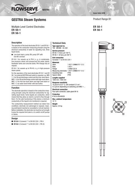
Issue Date: 6/08<strong>GESTRA</strong> <strong>Steam</strong> <strong>Systems</strong>Multiple Level Control ElectrodesER 50-1ER 56-1Product Range B1ER 50-1ER 56-1DescriptionThe operation of the level electrodes ER 50-1 and ER 56-1is based on the conductive measuring principle using theelectrical conductivity of water for signalling max. threeliquid levels:■ Low-level alarm, pump ON, pump OFF withone NO conctactER 50-1 for vessels up to PN 6, e. g. in condensate,low-pressure steam and pressurized hot-water plants,feedwater tanks and concrete tanks. PN 6 flange only onrequest.ER 56-1 for vessels up to PN 40, e. g. in high-pressuresteam plants.For the operation of the level electrodes ER 50-1 and ER56-1 an external <strong>GESTRA</strong> level switch is required, e.g. NRS1-1 for fill and discharge control and first low-level alarm,NRS 1-5 for fill and discharge control with high-level alarm,NRS 1-2 for first low-level alarm and high-level alarm orNRS 1-3 as water level limiter with test button.FunctionThe electrode operation is based on the conductive measuringprinciple using the electrical conductivity for signallingliquid levels. Some liquids are conductive, whichmeans that they allow an electric current to flow throughthem. For the safe functioning of this device a minimumconductivity of the liquid to be monitored is required.The conductivity measurement method can detect twoconditions: electrode rod submerged or exposed, meaningswitchpoint reached (or exceeded) or not yet reached.Before installation, the electrode rod must be cut to lengthto give the required limit alarm or to switch on/off pumpsor valves.Technical DataType approval no.TÜV · WR/WB · 03-302Service pressureER 50-1: 6 bar g at 159 °C,ER 56-1: 32 bar g at 238 °CEnd connectionScrewed 1" to EN ISO 228-1MaterialsStem1.4571 CrNiMoTi17-12-2Body 1.4571Flange 1.0460 C22.8Measuring electrodes 1.4571 CrNiMoTi17-12-2Insulating tube PTFESpacer disks PTFELengths supplied1000 mm, 1500 mmResponse sensitivity10 μS/cm at 25 °C, cell constant 0.3 cm -10.5 μS/cm depending on switching unit NRS 1-...Electrical connectionFour-pole connector, cable gland M 16ProtectionIP 65 to EN 60529Max. ambient temperature70 °CWeightApprox. 0.8 kgDesign■ ER 50-1: Screwed 1" to EN ISO 228-1, PN 6.■ ER 56-1: Screwed 1" to EN ISO 228-1, PN 40.
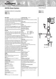
Multiple Level Control ElectrodesER 50-1ER 56-1Dimensions1"DN 50§$Important NotesFor the wiring to the electrodes use multi-core flexibleconduit, minimum conductor size 1.5 mm 2 .Order and Enquiry SpecificationsLevel electrode ER 50-1, PN 6Connection......................................................................Inspection.......................................................................Length supplied.........................................................mmLevel electrode ER 56-1, PN 40Connection......................................................................Inspection.......................................................................Length supplied.........................................................mmThe following test certificates can be issued onrequest, at extra cost:In accordance with EN 10204-2.1, -2.2, 3.1 and 3.2.All inspection requirements have to be stated with theorder. After supply of the equipment certificates can nolonger be established. Charges and extent of the abovementioned certificates as well as the different tests confirmedtherein are listed in our leaflet “Test and InspectionCharges for Standard Equipment”. For other tests andinspections than those listed above, please consult us.Associated Equipmentn Level controller type NRS 1-1b as fill or dischargecontroller with first low-level alarmn Level controller type NRS 1-5b as fill or dischargecontroller with high level alarmn Level switch type NRS 1-2b as low-level alarm andhigh-level alarmn Level switch type NRS 1-3b as low-level alarm withtest buttonKey§ Flange PN 40, DN 50, DIN 2527Flange PN 40, DN 100, DIN 2527$ For the approval of the boiler standpipe withconnecting flange the relevant regulations must beconsidered.% Vent hole& High water (HW)/ Electrode rod ∅ = 5 mm( Protection tube DN 80b Low water (LW)c Reducer DIN 2616 part 2, K88.9 x 3.242.4 x 2.6 Wd Reducer DIN 2616 part 2, K114.3 x 3.648.3 x 2.9 WATEX (Atmosphère Explosible)According to the European Directive 94/9/EC the equipmentmust not be used in explosion-risk areas.1000, 1500270∅ 42Fig. 1 ER 50-1, ER 56-11" to EN ISO 228DN 20DN 20ME&=≤ 90 °∅ 20 -5∅ 2020Fig. 2 Protection tube for installation ofelectrode inside the boiler≥ 20≥ 20%/(bc§$&/bSupply in accordance with our general termsof business.Fig. 3 External measuring potDN 20<strong>GESTRA</strong> <strong>AG</strong>P. O. Box 10 54 60, D-28054 BremenMünchener Str. 77, D-28215 BremenTelephone +49 (0) 421 35 03 - 0, Fax +49 (0) 421 35 03-393E-Mail gestra.ag@flowserve.com, Internet www.gestra.de810756-02/608cm · 2007 <strong>GESTRA</strong> <strong>AG</strong> · Bremen · Printed in Germany