
You also want an ePaper? Increase the reach of your titles
YUMPU automatically turns print PDFs into web optimized ePapers that Google loves.
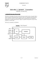
<strong>PICREF</strong>-4HARDWARE OVERVIEWLamp dimming using a TRIACLogic level TRIACS are a relatively new introduction.They allow a microcontroller to directly drive (througha current limiting resistor) the gate of a TRIAC.TRIACs can be used to control the brightness of alamp by switching the AC power on part-way througheach half wave (Figure 2 and Figure 3). By controllingwhere the TRIAC is "fired" during the power-line cycle,the microcontroller can control the average voltageacross the filament of the lamp, and thus thebrightness.The TRIAC used for this application is able to handlelamps up to a maximum of 100W.R9 is connected to the "hot" lead of the AC power lineand to pin GP4. The ESD protection diodes of theinput structure of the GPIO allows this connectionwithout damage (see Figure 1). When the voltage onthe AC power line is positive, the protection diode fromthe input to V DD is forward biased, and the input bufferwill see approximately V DD +0.7 volts and the softwarewill read the pin as high. When the voltage on the lineis negative, the protection diode from V SS to the inputpin is forward biased, and the input buffer seesapproximately V SS -0.7 volts and the software will readthe pin as low. By polling GP4 for a change in state,the software can detect a zero crossing.Since there is no transformer for power-lineisolation, the user must be very careful and assessthe risks from line-transients in his applicationlocation. The varistor (RV1) will add someprotection.The Power SupplyThe power supply used for this design uses onlydiscrete components and has no transformer orvoltage regulator making it extremely low cost. It hasbeen designed to handle either 60Hz or 50Hz inputpower, 120V nominal line voltage.The caveat to this low cost power supply is that it cannot provide large currents, and the user must take carenot to overload it.FIGURE 1:ZERO CROSSING DETECTIONPIC12C508 I/O structureVDDAC LineVoltageV DDR9 V SS20MGP4VDDPND QENVSSVSSRD Port© 1997 Microchip Technology Inc. DS40171A-page 3
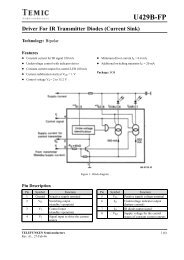
<strong>PICREF</strong>-4FIGURE 2:WAVEFORMSLine VoltageVoltage at Hot output lead,near full brightVoltage atPIC12C508, GP2FIGURE 3:OUTPUT VOLTAGE OF FULL-WAVE PHASE CONTROLφφ180Output Voltage1601401201008060Peak VoltageRMSAVG402000 20 40 60 80 100 120 140 160 180Conduction Angle φDS40171A-page 4© 1997 Microchip Technology Inc.
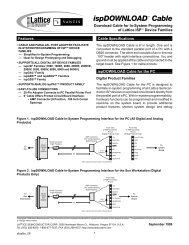
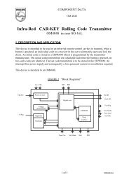
<strong>PICREF</strong>-4SOFTWARE OVERVIEWThe software is written in ’C’ using MPLABC, V1.21.There is only a main function and one function calledButtoncheck.Main FunctionInitializationThe main function begins by initializing all of the RAMregisters used, and setting the TRIS register so thatthe zero crossing sense, dim button, and bright buttonpins are set as inputs, and so that the TRIAC drive pinis set to be an input. The OPTION register is set toassign the prescaler to the timer with a ratio of 1:64,timer to increment on internal clock, and enable theweak pull-up resistors on GP0, GP1, and GP3.The next statement sets the output latch of GP2 (theoutput to the TRIAC) high. Note that this statementonly sets the output latch high. Since it is set to be aninput at this point, the pin will be at high-impedance.Because the internal RC oscillator of the PIC12C508can vary with temperature and supply voltage (the Vddsupply should be fairly constant at 5V), the programconstantly keeps track of the total Timer0 count ofeach half cycle of the AC line. If this were not doneand the count was too long for maximum dimming, theTRIAC would be fired shortly after the next half-cyclehad begun and actually cause the lamp to be on fullbright instead of full dim. The rest of the code beforeentering the main program loop synchronizes theTimer0 count with the line voltage so that the linefrequency/Timer0 count is known.Main Program LoopThe main program loop counts the line cycles andcalls Buttoncheck after DelayCnt cycles. If it is nottime to call Buttoncheck, two short routines are run,one for the positive and one for the negative half-cycleof the AC line. The routines are identical except for theline polarity checking, so only one will be described.The line phase is checked to see if the next half-cyclehas already begun. If it has, Maxdim is incrementedand a wait state is initiated to re-synch with the linevoltage. If it hasn’t, the program waits for the linevoltage to cross zero and when it does, resets Maxdimto match the half-cycle time. If the selectedon-percentage is selected to be greater than full dim, itis reset to give full dim.The timer is set to time out when the TRIAC should befired for the desired brightness. The program thengoes into a loop to wait for either the timer to roll overto zero, or for the AC line half cycle to expire.The TRIAC is then fired by setting the pin connected toit’s gate to be an output (the output latch was alreadyset high) to supply current into the gate. A short delayis initiated to widen the firing pulse before againsetting the pin to a high-impedance. The TRIAC willshut off when the AC line voltage next crosses zero.Buttoncheck SubroutineThis subroutine checks for presses of the BRT andDIM buttons and increments or decrementsPercenton based on their states.If both buttons are pressed and the lamp is not off, it isturned off. If it is already off, it is turned on full bright.In addition to taking commands from the buttons, atest function is built in to this routine. The test mode isentered by holding both buttons, and then releasingand pressing DIM again. The test will run for 255cycles or until the DIM button is pressed. The testruns in a cycle of brightening to full bright, dimming tofull dim and then flashing full bright twice.After the section of Buttoncheck where the testcycling is done if the program is in test mode, theprogram checks the buttons for the sequence to entertest mode, and looks for a both pressed for instant onor off. Following this code is the single button up anddown commands with checking for more than fullbright and less than full dim.DESIGN MODIFICATIONSThis reference design will work for many applicationswithout modification. It is anticipated that customersmay want to customize its functionality, however, andthis section offers suggestions for modification:• The software was written for a 60Hz line frequencyand might work on a 50HZ line, but hasnot been tested at anything but 60Hz.• Modify the circuit to use a single button. For thismodification, pressing the button would turn thelamp on and off, and if held, would graduallybrighten the lamp to full bright, then gradually dimto full dim. The brightness would stay at whateverlevel it was at when the button was released.• Add a light level sensor such that if full darknesswas sensed when the button was pressed, thelamp would gradually brighten to avoid shockingeyes adjusted for darkness.• Add a sensor to automatically switch the lamp onand off based on the room occupancy.• Use the two available pins to add a serial bus forcontrol from remote computer.• Add a "Halloween" mode that would flash thelamp at random times for a short period to simulatespooky lightning and such.• Add a photo sensor to maintain a given brightnesslevel in a room depending on ambient light.© 1997 Microchip Technology Inc. DS40171A-page 5
<strong>PICREF</strong>-4FIGURE 4:SOFTWARE FLOWCHART, MAIN PROGRAM LOOPStartInitializeVariablesSync to ACPowerlineLineAlreadyLow?NoYesIncrement Maxdimand resyncTimeto checkbuttons?YesCallButtonPressWait for ZeroCrossingCompensateMaxdimNoInitialize TMR0LineAlreadyHigh?NoYesIncrement Maxdimand resyncTimerRollover orZero Cross?NoWait for ZeroCrossingYesCompensateMaxdimFire TRIACFirstPass?YesSet for fulldimNoInitialize TMR0TimerRollover orZero Cross?NoYesFire TRIACDS40171A-page 6© 1997 Microchip Technology Inc.
<strong>PICREF</strong>-4FIGURE 5:SOFTWARE FLOWCHART, FUNCTION BUTTONPRESSButtonpressIn TestMode?YesDimPressed?YesCancel Test ModeReturnNoNoModify Percent OnBoth buttonsPressed?NoYesPercentOn =Maxdim?NoYesPercentOn =MaxbrtPercentOn =MaxdimHasCycle run255 times?NoReturnOnlyDIMPressed?NoYesDecrementPercentOnYesCancel Test ModeReturnOnlyBRTPressed?YesIncrementPercentOnNoPercentOn>Maxbrt?YesPercentOn =MaxbrtReturnNoPercentOn
<strong>PICREF</strong>-4NOTES:DS40171A-page 8© 1997 Microchip Technology Inc.
<strong>PICREF</strong>-4APPENDIX A: SYSTEM SPECIFICATIONSThe following is a list of specifications for the Lamp dimmer:AC Input: 120 VAC ± 10%, 60Hz ± 3HzOutput: 100W, resistive load only!APPENDIX B: BILL OF MATERIALSDescription Qty Designators Part #, Manufacturer, Contact #Resistor, 1/4 Watt, 47ohm,1 R1 GenericAxial LeadResistor, 1/4 Watt, 475ohm,3 R4, R5, R6 GenericAxial LeadResistor, 1/4 Watt, 1Mohm,1 R2 GenericAxial LeadResistor, 1/4 Watt, 20Mohm,1 R3 GenericAxial Lead8 Pin, 8-Bit, CMOS, Microcontroller 1 U1 12C508, Microchip Technology, Inc.(602) 786-7200Logic Triac, TO-202AB, 400V 1 Q1 L4004F51, Teccor Electronics Inc.(214) 580-1515Zener Diode, 5.1V, DO-35 1 D3 1N5231BCT, Diodes Incorporated/Digi-Key(800) 344-4539Diode 2 D1, D2 1N4001, GenericKeyswitch, Momentary PCB Mount 2 S1, S2 BF3-1000, Omron(847) 843-7900ZNR Transient/Surge Absorbers,1250A Surge, 300VDC, 230VACAluminum Electrolytic Capacitor,220uF, 35VAxial Ceramic Capacitor,0.01uF, 50VPolyester & Foil Capacitor,0.1uF, 200V1 RV1 ERZ-V07D361, Panasonic(206) 395-73431 C1 ECE-A1VU221, Panasonic(206) 395-73431 C2 A103Z15Z5UFVVWA, Philips(602) 820-22251 C3 ECQ-M2104KZ, Panasonic(206) 395-7343TABLE 1:BUTTON FUNCTIONSButtonBRTDIMHold DIM, Press BRTHold BRT, Press, release,and press DIM again. To exittest mode, press DIM.FunctionBrightenDimIf off: turn full on, if on: turn offEnter test/demo mode© 1997 Microchip Technology Inc. DS40171A-page 9
<strong>PICREF</strong>-4FIGURE 6:CIRCUIT DIAGRAMReturn (White)Hot outHot inJP2321DANGERElectrocution HazardRV1VARISTORS2BrightS1DimR147R320MJP1321+5VC3.1uFR21M1234U1VDDGP5GP4GP312C508VSSGP0GP1GP28765R4R5470D11N4001D21N4001D31N5231R6470C1220uFwhite (return)VCCC2.01hotQ1L4004F51DS40171A-page 10© 1997 Microchip Technology Inc.
<strong>PICREF</strong>-4APPENDIX C:SOFTWARE PROGRAM#pragma option v;#include /********************************************************//* DIMMER.C/*/* Lamp dimmer for the 12C508./* This program uses the internal 4MHz oscillator/* To drive TRIAC, the output is taken high/* or put in high-impeadance(open drain) to release it/*/* NOTE: This program is designed to work with a 60Hz/* line frequency, it must be modified if used/* on a 50Hz AC line./*/* GPIO = Dim button/* GPIO = No Connect/* GPIO = Output to TRIAC/* GPIO = Bright Button/* GPIO = Zero Crossing sense input/* GPIO = No Connect/********************************************************/#defineBrtbut GPIO.0//Brighten button#define Output GPIO.2//Output to TRIAC#define Dimbut GPIO.3//Dim button#define LineInput GPIO.4//AC line zero crossing sensevoid Buttoncheck(void);unsigned int PercentOn, Maxdim;unsigned int TestCheck, Outcount, TestCount;unsigned int DelayCnt;unsigned int LastBoth, FirstPass;unsigned int Count;const Maxbrt = 0xFD, NotInTest = 3;void main(){PercentOn = 0xD0;Maxdim = 0x70;TestCheck = 0;Outcount = 0;TestCount = 0;DelayCnt = NotInTest;LastBoth = 0;FirstPass = 1;Count = 0;for(Count = 0; Count < 60; Count++){while(LineInput == 1);while(LineInput == 0);CLRWDT;}WREG = 0x85;#asm ( OPTION);WREG = 0x1D;#asm ( TRIS GPIO);//Button check routine//Global variables//On Period//Value of Maximum dimming//Test mode check counter//Counter for test mode exit//Test mode counter//Delay count//Both buttons pressed last time flag//Indicate power-up//General counter//Allow power supply to stabilize//1:64 tmr0 prescaler, pullups enabled//Set up I/OGPIO = 0x04;//Set TRIAC output latch highwhile(LineInput == 1)CLRWDT;TMR0 = PercentOn;while(TMR0 >= 3 && LineInput == 0)CLRWDT;while(1)//Synch to line phase//Get Delay time//Delay to enter main at proper point//Stay in this loop© 1997 Microchip Technology Inc. DS40171A-page 11
<strong>PICREF</strong>-4{Count = 0;while (Count++ < DelayCnt){if(LineInput == 1){Maxdim += 5;while(LineInput == 1);while(LineInput == 0)CLRWDT;}else{while(LineInput == 0)CLRWDT;Maxdim = PercentOn - TMR0 + 2;//Check for button press everyDelayCnt zero crossings//Check for AC line already high//If so, increment Maxdim// and re-sync with line//Wait for zero crossing//Compensate full dim value for line// frequency vs osc. speed}if(FirstPass == 1)//If first pass, go to full dim{FirstPass = 0;PercentOn = Maxdim;}if(PercentOn < Maxdim)//If maxdim moved, fix brightnessPercentOn = Maxdim;TMR0 = PercentOn;//Get delay timewhile(TMR0 >= 3 && LineInput == 1) //Delay TRIAC turn on (wait for Counter rollover)CLRWDT;GPIO = 0x04;WREG = 0x19;#asm ( TRIS GPIO);NOP;NOP;NOP;NOP;NOP;NOP;NOP;WREG = 0x1D;#asm ( TRIS GPIO);CLRWDT;if(LineInput == 0){Maxdim += 5;while(LineInput == 0);while(LineInput == 1)CLRWDT;}else{while(LineInput==1)CLRWDT;Maxdim = PercentOn - TMR0 + 2;}if(PercentOn < Maxdim)PercentOn = Maxdim;TMR0 = PercentOn;while(TMR0 >= 3 && LineInput == 0)CLRWDT;GPIO = 0x04;WREG = 0x19;#asm ( TRIS GPIO);//Set TRIAC output latch high//Fire TRIAC//Delay for TRIAC fire pulse//Release TRIAC fire Signal//Check for AC line already low//If so, increment Maxdim// and re-sync with line//Wait for zero crossing//Compensate full dim value for line// frequency vs osc. speed//If maxdim moved, fix brightness//Get Delay time//Delay TRIAC turn on//Set TRIAC output latch high//Fire TRIACDS40171A-page 12© 1997 Microchip Technology Inc.
<strong>PICREF</strong>-4NOP;//Delay for TRIAC fire pulseNOP;NOP;NOP;NOP;NOP;NOP;WREG = 0x1D;#asm ( TRIS GPIO);//Release TRIAC fire signalCLRWDT;}Buttoncheck();//Check for button press}}/******************************************************** *//* ButtonCheck *//* *//* This subroutine checks for presses on the BRT and DIM *//* buttons and increments or decrements PercentOn. *//* *//* If both buttons are pressed and the lamp *//* is not off, it is turned off, if off, it is set to *//* to max bright. *//* *//* In addition, a test function is built in. If both *//* buttons are pressed, the dim let go and then pressed *//* again, test mode is entered. If dim is pressed *//* (alone), the program goes to normal operation at max *//* dim. The test mode brightens to full bright, dims to *//* full dim, flashes full bright twice, and repeats. *//******************************************************** */void Buttoncheck(){NOP; //Bugfix for MPLABC V1.10if(TestCheck == 3)//Check test mode flag{DelayCnt = 2;//Reset the delay countif(Brtbut && !Dimbut)//If Dimbutton pressed, exit test mode{TestCheck = 0;//Clear Test mode flagDelayCnt = 5;return;}if(TestCount == 0)//Ramp up to full dim{if(++PercentOn > Maxbrt)//Check for full bright{PercentOn = Maxbrt;++TestCount;return;}elsereturn;}if(TestCount == 1)//Ramp down to full dim{if(--PercentOn
<strong>PICREF</strong>-4}return;while(TestCount++ < 10){PercentOn = Maxdim;return;}while(TestCount++ < 15){PercentOn = Maxbrt;return;}while(TestCount++ < 20){PercentOn = Maxdim;return;}while(TestCount++ < 25){PercentOn = Maxbrt;return;}while(TestCount++ < 30){PercentOn = Maxdim;return;}PercentOn = Maxdim;TestCount = 0;if(++Outcount == 255){TestCheck = 0;DelayCnt = NotInTest;Outcount = 0;}return;//Turn off for a short period//Turn On for a short period//Turn off for a short period//Turn on for a short period//Turn off for a short period//Reset to beggining of test sequence//Run 255 cycles of test mode//Clear Test mode flagif(TestCheck)if(++Outcount == 0x60){DelayCnt = NotInTest;Outcount = 0;TestCheck = 0;}if(!TestCheck && !Brtbut && !Dimbut)TestCheck = 1;if(TestCheck == 1 && !Brtbut && Dimbut)TestCheck = 2;if(TestCheck == 2 && !Brtbut && !Dimbut){TestCheck = 3;TestCount = 0;PercentOn = Maxdim;Outcount = 0;}if(!Dimbut && !Brtbut){if(LastBoth == 0){LastBoth = 1;if(PercentOn == Maxdim)PercentOn = Maxbrt;elsePercentOn = Maxdim;}}//If Test mode not entered quickly,// quit checking//Check bright & dim at same time//If both pressed, set to look for next combo//Check for only bright button pressed//If pressed, set to look for next combo//Check for both pressed again//Enable test mode//If both pressed//Don't flash if held//If full off...// turn full on...// otherwise turn offDS40171A-page 14© 1997 Microchip Technology Inc.
<strong>PICREF</strong>-4}elseLastBoth = 0;if(!Brtbut && Dimbut)PercentOn ++;if(Brtbut && !Dimbut)PercentOn --;if(PercentOn > Maxbrt)PercentOn = Maxbrt;if(PercentOn < Maxdim)PercentOn = Maxdim;//Check for brighten cmd//Check for dim cmd//If greater than full bright//If less than full dim© 1997 Microchip Technology Inc. DS40171A-page 15
<strong>PICREF</strong>-4NOTES:DS40171A-page 16© 1997 Microchip Technology Inc.
<strong>PICREF</strong>-4APPENDIX D:DIM508.LST FILEMPLAB-C "C" COMPILER V1.21 Released PAGE 1#pragma option v;#include #ifndef _12C508_H/*PIC12C508 Standard Header File, Version 1.02(c) Copyright 1996 Microchip Technology, Inc., Byte Craft LimitedRAM locations reserved for temporary variables: 0x07*/#pragma option +l;#endif/********************************************************//* DIMMER.C *//* *//* Lamp dimmer for the 12C508. *//* This program uses the internal 4MHz oscillator *//* To drive TRIAC, the output is taken high *//* or put in high-impeadance(open drain) to release it*//* *//* NOTE: This program is designed to work with a 60Hz *//* line frequency, it must be modified if used *//* on a 50Hz AC line. *//* *//* GPIO = Dim button *//* GPIO = No Connect *//* GPIO = Output to TRIAC *//* GPIO = Bright Button *//* GPIO = Zero Crossing sense input *//* GPIO = No Connect *//********************************************************/0007 #define Brtbut GPIO.0 //Brighten button0008 #define Output GPIO.2 //Output to TRIAC0009 #define Dimbut GPIO.3 //Dim button000A #define LineInput GPIO.4 //AC line zero crossing sensevoid Buttoncheck(void); //Button check routine0008 0009 unsigned int PercentOn, Maxdim ; //Global variables000A 000B 000Cunsigned int TestCheck, Outcount, TestCount;000Dunsigned int DelayCnt;000E 000Funsigned int LastBoth, FirstPass;0010 unsigned int Count;007E 0001 const Maxbrt = 0xFD, NotInTest = 3;void main(){0001 0CD0 MOVLW D0h PercentOn = 0xD0; //On Period0002 0028 MOVWF 080003 0C70 MOVLW 70h Maxdim = 0x70; //Value of Maximum dimming0004 0029 MOVWF 090005 006A CLRF 0A TestCheck = 0; //Test mode check counter0006 006B CLRF 0B Outcount = 0; //Counter for test mode exit0007 006C CLRF 0C TestCount = 0; //Test mode counter0008 0C03 MOVLW 03h DelayCnt = NotInTest; //Delay count0009 002D MOVWF 0D000A 006E CLRF 0E LastBoth = 0; //Both buttons pressed last time flag000B 0C01 MOVLW 01h FirstPass = 1; //Indicate power-up000C 002F MOVWF 0F000D 0070 CLRF 10 Count = 0; //General counter000E 0070 CLRF 10 for(Count = 0; Count < 60; Count++) //Allow power supplyto stabilize000F 0C3C MOVLW 3Ch0010 0090 SUBWF 10,W0011 0603 BTFSC 03,00012 0A1A GOTO 001Ah{© 1997 Microchip Technology Inc. DS40171A-page 17
<strong>PICREF</strong>-40013 0686 BTFSC 06,4 while(LineInput == 1);0014 0A13 GOTO 0013h0015 0786 BTFSS 06,4 while(LineInput == 0);0016 0A15 GOTO 0015h0017 0004 CLRWDT CLRWDT;}0018 02B0 INCF 100019 0A0F GOTO 000FhWREG = 0x85;001A 0C85 MOVLW 85h #asm ( OPTION);001B 0002 OPTIONWREG = 0x1D;001C 0C1D MOVLW 1Dh #asm ( TRIS GPIO);001D 0006 TRIS PORTB// __OPTION(0x85); //1:64 tmr0 prescaler, pullups enabled// __TRIS(0x1D,GPIO); //Set up I/O001E 0C04 MOVLW 04h GPIO = 0x04; //Set TRIAC output latch high001F 0026 MOVWF 06while(LineInput == 1)//Synch to line phase0020 0786 BTFSS 06,40021 0A24 GOTO 0024h0022 0004 CLRWDT CLRWDT;0023 0A20 GOTO 0020h0024 0208 MOVF 08,W TMR0 = PercentOn; //Get Delay time0025 0021 MOVWF 010026 0C03 MOVLW 03h while(TMR0 >= 3 && LineInput == 0) //Delay to enter mainat proper point0027 0081 SUBWF 01,W0028 0703 BTFSS 03,00029 0A2E GOTO 002Eh002A 0686 BTFSC 06,4002B 0A2E GOTO 002Eh002CCLRWDT;002C 0004 CLRWDT002D 0A26 GOTO 0026hwhile(1)//Stay in this loop{002E 0070 CLRF 10002F Count = 0;while (Count++ < DelayCnt)//Check for button press everyDelayCnt zero crossings002F 0210 MOVF 10,W {0030 02B0 INCF 100031 008D SUBWF 0D,W0032 0743 BTFSS 03,20033 0703 BTFSS 03,00034 0AA5 GOTO 00A5h0035 if(LineInput == 1) //Check for AC line already high0035 0786 BTFSS 06,4 {0036 0A40 GOTO 0040h0037 0C05 MOVLW 05h Maxdim += 5; //If so, increment Maxdim0038 01E9 ADDWF 090039 0686 BTFSC 06,4 while(LineInput == 1); // and re-sync with line003A 0A39 GOTO 0039h003B 0686 BTFSC 06,4 while(LineInput == 0)003C 0A3F GOTO 003Fh003DCLRWDT;003D 0004 CLRWDT003E 0A3B GOTO 003Bh}003F 0A4A GOTO 004Ah else{0040 0686 BTFSC 06,4 while(LineInput == 0) //Wait for zero crossing0041 0A44 GOTO 0044h0042 CLRWDT;0042 0004 CLRWDTDS40171A-page 18© 1997 Microchip Technology Inc.
<strong>PICREF</strong>-40043 0A40 GOTO 0040h0044 0201 MOVF 01,W Maxdim = PercentOn - TMR0 + 2; //Compensate full dimvalue for line0045 0088 SUBWF 08,W0046 0027 MOVWF 070047 0C02 MOVLW 02h0048 01C7 ADDWF 07,W0049 0029 MOVWF 09// frequency vs osc. speed}004A 0C01 MOVLW 01h if(FirstPass == 1) //If first pass, go to full dim004B 008F SUBWF 0F,W004C 0743 BTFSS 03,2004D 0A51 GOTO 0051h004E {004E 006F CLRF 0F FirstPass = 0;004F 0209 MOVF 09,W PercentOn = Maxdim;0050 0028 MOVWF 08}0051 0209 MOVF 09,W if(PercentOn < Maxdim) //If maxdim moved, fix brightness0052 0088 SUBWF 08,W0053 0743 BTFSS 03,20054 0603 BTFSC 03,00055 0A58 GOTO 0058h0056 0209 MOVF 09,W PercentOn = Maxdim;0057 0028 MOVWF 080058 0208 MOVF 08,W TMR0 = PercentOn; //Get delay time0059 0021 MOVWF 01005A 0C03 MOVLW 03h while(TMR0 >= 3 && LineInput == 1) //Delay TRIAC turn on(wait for Counter rollover)005B 0081 SUBWF 01,W005C 0703 BTFSS 03,0005D 0A62 GOTO 0062h005E 0786 BTFSS 06,4005F 0A62 GOTO 0062h0060 CLRWDT;0060 0004 CLRWDT0061 0A5A GOTO 005Ah0062 0C04 MOVLW 04h GPIO = 0x04; //Set TRIAC output latch high0063 0026 MOVWF 06WREG = 0x19;0064 0C19 MOVLW 19h #asm ( TRIS GPIO);0065 0006 TRIS PORTB// __TRIS(0x19,GPIO); //Fire Triac0066 0000 NOP NOP; //Delay for TRIAC fire pulse0067 0000 NOP NOP;0068 0000 NOP NOP;0069 0000 NOP NOP;006A 0000 NOP NOP;006B 0000 NOP NOP;006C 0000 NOP NOP;WREG = 0x1D;006D 0C1D MOVLW 1Dh #asm ( TRIS GPIO);006E 0006 TRIS PORTB// __TRIS(0x1D,GPIO); //Release TRIAC fire signal006F 0004 CLRWDT CLRWDT;0070 0686 BTFSC 06,4 if(LineInput == 0) //Check for AC line already low0071 0A7B GOTO 007Bh0072 {0072 0C05 MOVLW 05h Maxdim += 5; //If so, increment Maxdim0073 01E9 ADDWF 090074 0786 BTFSS 06,4 while(LineInput == 0); // and re-sync with line0075 0A74 GOTO 0074hwhile(LineInput == 1)© 1997 Microchip Technology Inc. DS40171A-page 19
<strong>PICREF</strong>-40076 0786 BTFSS 06,40077 0A7A GOTO 007Ah0078 0004 CLRWDT CLRWDT;0079 0A76 GOTO 0076h}007A 0A85 GOTO 0085h else{while(LineInput==1) //Wait for zero crossing007B 0786 BTFSS 06,4007C 0A7F GOTO 007Fh007D 0004 CLRWDT CLRWDT;007E 0A7B GOTO 007Bh007F 0201 MOVF 01,W Maxdim = PercentOn - TMR0 + 2; //Compensate full dim value forline0080 0088 SUBWF 08,W0081 0027 MOVWF 070082 0C02 MOVLW 02h0083 01C7 ADDWF 07,W0084 0029 MOVWF 09// frequency vs osc. speed}0085 0209 MOVF 09,W if(PercentOn < Maxdim) //If maxdim moved, fix brightness0086 0088 SUBWF 08,W0087 0743 BTFSS 03,20088 0603 BTFSC 03,00089 0A8C GOTO 008Ch008A 0209 MOVF 09,W PercentOn = Maxdim;008B 0028 MOVWF 08008C 0208 MOVF 08,W TMR0 = PercentOn; //Get Delay time008D 0021 MOVWF 01008E 0C03 MOVLW 03h while(TMR0 >= 3 && LineInput == 0) //Delay TRIAC turn on008F 0081 SUBWF 01,W0090 0703 BTFSS 03,00091 0A96 GOTO 0096h0092 0686 BTFSC 06,40093 0A96 GOTO 0096h0094 CLRWDT;0094 0004 CLRWDT0095 0A8E GOTO 008Eh0096 0C04 MOVLW 04h GPIO = 0x04; //Set TRIAC output latch high0097 0026 MOVWF 06WREG = 0x19;0098 0C19 MOVLW 19h #asm ( TRIS GPIO);0099 0006 TRIS PORTB// __TRIS(0x19,GPIO); //Fire TRIAC009A 0000 NOP NOP; //Delay for TRIAC fire pulse009B 0000 NOP NOP;009C 0000 NOP NOP;009D 0000 NOP NOP;009E 0000 NOP NOP;009F 0000 NOP NOP;00A0 0000 NOP NOP;WREG = 0x1D;00A1 0C1D MOVLW 1Dh #asm ( TRIS GPIO);00A2 0006 TRIS PORTB// __TRIS(0x1D,GPIO); //Release TRIAC fire signal00A3 0004 CLRWDT CLRWDT;00A4 0A2F GOTO 002Fh }00A5 09A8 CALL 00A8h Buttoncheck(); //Check for button press00A6 0A2E GOTO 002Eh }00A7 0800 RETLW 00h }/********************************************************//* ButtonCheck *//* *//* This subroutine checks for presses on the BRT and DIM*//* buttons and increments or decrements PercentOn. */DS40171A-page 20© 1997 Microchip Technology Inc.
<strong>PICREF</strong>-4/* *//* If both buttons are pressed and the lamp *//* is not off, it is turned off, if off, it is set to *//* to max bright. *//* *//* In addition, a test function is built in. If both *//* buttons are pressed, the dim let go and then pressed *//* again, test mode is entered. If dim is pressed *//* (alone), the program goes to normal operation at max *//* dim. The test mode brightens to full bright, dims to*//* full dim, flashes full bright twice, and repeats. *//********************************************************/void Buttoncheck(){00A8 0000 NOP NOP; //Bugfix for MPLABC V1.1000A9 0C03 MOVLW 03h if(TestCheck == 3) //Check test mode flag00AA 008A SUBWF 0A,W00AB 0743 BTFSS 03,200AC 0B1B GOTO 011Bh00AD {00AD 0C02 MOVLW 02h DelayCnt = 2; //Reset the delay count00AE 002D MOVWF 0D00AF 0706 BTFSS 06,0 if(Brtbut && !Dimbut) //If Dimbutton pressed, exit test mode00B0 0AB7 GOTO 00B7h00B1 0666 BTFSC 06,300B2 0AB7 GOTO 00B7h00B3 {00B3 006A CLRF 0A TestCheck = 0; //Clear Test mode flag00B4 0C05 MOVLW 05h DelayCnt = 5;00B5 002D MOVWF 0D00B6 0800 RETLW 00h return;}00B7 022C MOVF 0C if(TestCount == 0) //Ramp up to full dim00B8 0743 BTFSS 03,200B9 0AC5 GOTO 00C5h00BA {00BA 02A8 INCF 08 if(++PercentOn > Maxbrt) //Check for full bright00BB 0CFD MOVLW FDh00BC 0088 SUBWF 08,W00BD 0743 BTFSS 03,200BE 0703 BTFSS 03,000BF 0AC4 GOTO 00C4h00C0 {00C0 0CFD MOVLW FDh PercentOn = Maxbrt;00C1 0028 MOVWF 0800C2 02AC INCF 0C ++TestCount;00C3 0800 RETLW 00h return;}else00C4 0800 RETLW 00h return;}00C5 0C01 MOVLW 01h if(TestCount == 1) //Ramp down to full dim00C6 008C SUBWF 0C,W00C7 0743 BTFSS 03,200C8 0AD5 GOTO 00D5h00C9 {00C9 00E8 DECF 08 if(--PercentOn
<strong>PICREF</strong>-400D2 02AC INCF 0C ++TestCount;00D3 0800 RETLW 00h return;}else00D4 0800 RETLW 00h return;}00D5 020C MOVF 0C,W while(TestCount++ < 5) //Delay00D6 02AC INCF 0C00D7 0027 MOVWF 0700D8 0C05 MOVLW 05h00D9 0087 SUBWF 07,W00DA 0703 BTFSS 03,000DBreturn;00DB 0800 RETLW 00hwhile(TestCount++ < 10) //Turn off for a short period00DC 020C MOVF 0C,W {00DD 02AC INCF 0C00DE 0027 MOVWF 0700DF 0C0A MOVLW 0Ah00E0 0087 SUBWF 07,W00E1 0603 BTFSC 03,000E2 0AE6 GOTO 00E6h00E3PercentOn = Maxdim;00E3 0209 MOVF 09,W00E4 0028 MOVWF 0800E5 0800 RETLW 00h return;}while(TestCount++ < 15) //Turn On for a short period00E6 020C MOVF 0C,W {00E7 02AC INCF 0C00E8 0027 MOVWF 0700E9 0C0F MOVLW 0Fh00EA 0087 SUBWF 07,W00EB 0603 BTFSC 03,000EC 0AF0 GOTO 00F0h00EDPercentOn = Maxbrt;00ED 0CFD MOVLW FDh00EE 0028 MOVWF 0800EF 0800 RETLW 00h return;}while(TestCount++ < 20) //Turn off for a short period00F0 020C MOVF 0C,W {00F1 02AC INCF 0C00F2 0027 MOVWF 0700F3 0C14 MOVLW 14h00F4 0087 SUBWF 07,W00F5 0603 BTFSC 03,000F6 0AFA GOTO 00FAh00F7PercentOn = Maxdim;00F7 0209 MOVF 09,W00F8 0028 MOVWF 0800F9 0800 RETLW 00h return;}while(TestCount++ < 25) //Turn on for a short period00FA 020C MOVF 0C,W {00FB 02AC INCF 0C00FC 0027 MOVWF 0700FD 0C19 MOVLW 19h00FE 0087 SUBWF 07,W00FF 0603 BTFSC 03,00100 0B04 GOTO 0104h0101 PercentOn = Maxbrt;0101 0CFD MOVLW FDh0102 0028 MOVWF 080103 0800 RETLW 00h return;}DS40171A-page 22© 1997 Microchip Technology Inc.
<strong>PICREF</strong>-4while(TestCount++ < 30) //Turn off for a short period0104 020C MOVF 0C,W {0105 02AC INCF 0C0106 0027 MOVWF 070107 0C1E MOVLW 1Eh0108 0087 SUBWF 07,W0109 0603 BTFSC 03,0010A 0B0E GOTO 010Eh010BPercentOn = Maxdim;010B 0209 MOVF 09,W010C 0028 MOVWF 08010D 0800 RETLW 00h return;}010E 0209 MOVF 09,W PercentOn = Maxdim;010F 0028 MOVWF 080110 006C CLRF 0C TestCount = 0; //Reset to beggining of test sequence0111 02AB INCF 0B if(++Outcount == 255) //Run 255 cycles of test mode0112 0CFF MOVLW FFh0113 008B SUBWF 0B,W0114 0743 BTFSS 03,20115 0B1A GOTO 011Ah0116 {0116 006A CLRF 0A TestCheck = 0; //Clear Test mode flag0117 0C03 MOVLW 03h DelayCnt = NotInTest;0118 002D MOVWF 0D0119 006B CLRF 0B Outcount = 0;}011A 0800 RETLW 00h return;}011B 022A MOVF 0A if(TestCheck) //If Test mode not entered quickly,011C 0643 BTFSC 03,2011D 0B27 GOTO 0127h011E if(++Outcount == 0x60) // quit checking011E 02AB INCF 0B {011F 0C60 MOVLW 60h0120 008B SUBWF 0B,W0121 0743 BTFSS 03,20122 0B27 GOTO 0127h0123 0C03 MOVLW 03h DelayCnt = NotInTest;0124 002D MOVWF 0D0125 006B CLRF 0B Outcount = 0;0126 006A CLRF 0A TestCheck = 0;}0127 022A MOVF 0A if(!TestCheck && !Brtbut && !Dimbut) //Check bright & dimat same time0128 0743 BTFSS 03,20129 0B30 GOTO 0130h012A 0606 BTFSC 06,0012B 0B30 GOTO 0130h012C 0666 BTFSC 06,3012D 0B30 GOTO 0130h012E 0C01 MOVLW 01h TestCheck = 1; //If both pressed, set to look for next combo012F 002A MOVWF 0A0130 0C01 MOVLW 01h if(TestCheck == 1 && !Brtbut && Dimbut) //Check for only brightbutton pressed0131 008A SUBWF 0A,W0132 0743 BTFSS 03,20133 0B3A GOTO 013Ah0134 0606 BTFSC 06,00135 0B3A GOTO 013Ah0136 0766 BTFSS 06,30137 0B3A GOTO 013Ah0138 0C02 MOVLW 02h TestCheck = 2; //If pressed, set to look for next combo0139 002A MOVWF 0A© 1997 Microchip Technology Inc. DS40171A-page 23
<strong>PICREF</strong>-4013A 0C02 MOVLW 02h if(TestCheck == 2 && !Brtbut && !Dimbut) //Check for bothpressed again013B 008A SUBWF 0A,W013C 0743 BTFSS 03,2013D 0B48 GOTO 0148h013E 0606 BTFSC 06,0013F 0B48 GOTO 0148h0140 0666 BTFSC 06,30141 0B48 GOTO 0148h0142 {0142 0C03 MOVLW 03h TestCheck = 3; //Enable test mode0143 002A MOVWF 0A0144 006C CLRF 0C TestCount = 0;0145 0209 MOVF 09,W PercentOn = Maxdim;0146 0028 MOVWF 080147 006B CLRF 0B Outcount = 0;}0148 0666 BTFSC 06,3 if(!Dimbut && !Brtbut) //If both pressed0149 0B5B GOTO 015Bh014A 0606 BTFSC 06,0014B 0B5B GOTO 015Bh014C {014C 022E MOVF 0E if(LastBoth == 0) //Don't flash if held014D 0743 BTFSS 03,2014E 0B5A GOTO 015Ah014F {014F 0C01 MOVLW 01h LastBoth = 1;0150 002E MOVWF 0E0151 0208 MOVF 08,W if(PercentOn == Maxdim) //If full off...0152 0089 SUBWF 09,W0153 0743 BTFSS 03,20154 0B58 GOTO 0158h0155 0CFD MOVLW FDh PercentOn = Maxbrt; // turn full on...0156 0028 MOVWF 080157 0B5A GOTO 015Ah else0158 0209 MOVF 09,W PercentOn = Maxdim; // otherwise turn off0159 0028 MOVWF 08}}015A 0B5C GOTO 015Ch else015B 006E CLRF 0E LastBoth = 0;015C 0606 BTFSC 06,0 if(!Brtbut && Dimbut) //Check for brighten cmd015D 0B60 GOTO 0160h015E 0666 BTFSC 06,3015F 02A8 INCF 08 PercentOn ++;0160 0706 BTFSS 06,0 if(Brtbut && !Dimbut) //Check for dim cmd0161 0B64 GOTO 0164h0162 0766 BTFSS 06,30163 00E8 DECF 08 PercentOn --;0164 0CFD MOVLW FDh if(PercentOn > Maxbrt) //If greater than full bright0165 0088 SUBWF 08,W0166 0743 BTFSS 03,20167 0703 BTFSS 03,00168 0B6B GOTO 016Bh0169 0CFD MOVLW FDh PercentOn = Maxbrt;016A 0028 MOVWF 08016B 0209 MOVF 09,W if(PercentOn < Maxdim) //If less than full dim016C 0088 SUBWF 08,W016D 0743 BTFSS 03,2016E 0603 BTFSC 03,0016F 0B72 GOTO 0172h0170 0209 MOVF 09,W PercentOn = Maxdim;0171 0028 MOVWF 080172 0800 RETLW 00h }0000 0A01 GOTO 0001hROM USAGE MAPDS40171A-page 24© 1997 Microchip Technology Inc.
<strong>PICREF</strong>-40000 to 0172Total ROM used 0173Errors : 0Warnings : 0© 1997 Microchip Technology Inc. DS40171A-page 25
<strong>PICREF</strong>-4NOTES:DS40171A-page 26© 1997 Microchip Technology Inc.
<strong>PICREF</strong>-4NOTES:© 1997 Microchip Technology Inc. DS40171A-page 27
MWORLDWIDE SALES & SERVICEAMERICASCorporate OfficeMicrochip Technology Inc.2355 West Chandler Blvd.Chandler, AZ 85224-6199Tel: 602-786-7200 Fax: 602-786-7277Technical Support: 602 786-7627Web: http://www.microchip.comAtlantaMicrochip Technology Inc.500 Sugar Mill Road, Suite 200BAtlanta, GA 30350Tel: 770-640-0034 Fax: 770-640-0307BostonMicrochip Technology Inc.5 Mount Royal AvenueMarlborough, MA 01752Tel: 508-480-9990 Fax: 508-480-8575ChicagoMicrochip Technology Inc.333 Pierce Road, Suite 180Itasca, IL 60143Tel: 630-285-0071 Fax: 630-285-0075DallasMicrochip Technology Inc.14651 Dallas Parkway, Suite 816Dallas, TX 75240-8809Tel: 972-991-7177 Fax: 972-991-8588DaytonMicrochip Technology Inc.Two Prestige Place, Suite 150Miamisburg, OH 45342Tel: 937-291-1654 Fax: 937-291-9175Los AngelesMicrochip Technology Inc.18201 Von Karman, Suite 1090Irvine, CA 92612Tel: 714-263-1888 Fax: 714-263-1338New YorkMicrochip Technology Inc.150 Motor Parkway, Suite 202Hauppauge, NY 11788Tel: 516-273-5305 Fax: 516-273-5335San JoseMicrochip Technology Inc.2107 North First Street, Suite 590San Jose, CA 95131Tel: 408-436-7950 Fax: 408-436-7955TorontoMicrochip Technology Inc.5925 Airport Road, Suite 200Mississauga, Ontario L4V 1W1, CanadaTel: 905-405-6279 Fax: 905-405-6253ASIA/PACIFICHong KongMicrochip Asia PacificRM 3801B, Tower TwoMetroplaza223 Hing Fong RoadKwai Fong, N.T., Hong KongTel: 852-2-401-1200 Fax: 852-2-401-3431IndiaMicrochip Technology Inc.India Liaison OfficeNo. 6, Legacy, Convent RoadBangalore 560 025, IndiaTel: 91-80-229-0061 Fax: 91-80-229-0062KoreaMicrochip Technology Korea168-1, Youngbo Bldg. 3 FloorSamsung-Dong, Kangnam-KuSeoul, KoreaTel: 82-2-554-7200 Fax: 82-2-558-5934ShanghaiMicrochip TechnologyRM 406 Shanghai Golden Bridge Bldg.2077 Yan’an Road West, Hong Qiao DistrictShanghai, PRC 200335Tel: 86-21-6275-5700Fax: 86 21-6275-5060SingaporeMicrochip Technology TaiwanSingapore Branch200 Middle Road#07-02 Prime CentreSingapore 188980Tel: 65-334-8870 Fax: 65-334-8850TaiwanMicrochip Technology Taiwan10F-1C 207Tung Hua North RoadTaipei, TaiwanTel: 886 2-717-7175 Fax: 886-2-545-0139EUROPEUnited KingdomArizona Microchip Technology Ltd.505 Eskdale RoadWinnersh TriangleWokinghamBerkshire, England RG41 5TUTel: 44-1189-21-5858 Fax: 44-1189-21-5835FranceArizona Microchip Technology SARLZone Industrielle de la Bonde2 Rue du Buisson aux Fraises91300 Massy, FranceTel: 33-1-69-53-63-20 Fax: 33-1-69-30-90-79GermanyArizona Microchip Technology GmbHGustav-Heinemann-Ring 125D-81739 Müchen, GermanyTel: 49-89-627-144 0 Fax: 49-89-627-144-44ItalyArizona Microchip Technology SRLCentro Direzionale ColleoniPalazzo Taurus 1 V. Le Colleoni 120041 Agrate BrianzaMilan, ItalyTel: 39-39-6899939 Fax: 39-39-6899883JAPANMicrochip Technology Intl. Inc.Benex S-1 6F3-18-20, ShinyokohamaKohoku-Ku, Yokohama-shiKanagawa 222 JapanTel: 81-45-471- 6166 Fax: 81-45-471-612210/31/97All rights reserved. © 1997, Microchip Technology Incorporated, USA. 11/97 Printed on recycled paper.Information contained in this publication regarding device applications and the like is intended for suggestion only and may be superseded by updates. No representation orwarranty is given and no liability is assumed by Microchip Technology Incorporated with respect to the accuracy or use of such information, or infringement of patents or otherintellectual property rights arising from such use or otherwise. Use of Microchip’s products as critical components in life support systems is not authorized except with expresswritten approval by Microchip. No licenses are conveyed, implicitly or otherwise, under any intellectual property rights. The Microchip logo and name are registered trademarksof Microchip Technology Inc. in the U.S.A. and other countries. All rights reserved. All other trademarks mentioned herein are the property of their respective companies.DS40171A-page 28 Preliminary © 1997 Microchip Technology Inc.