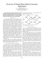
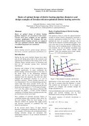
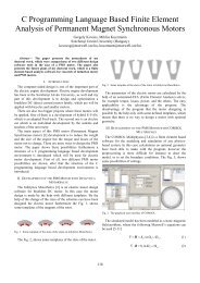
III. DRAG BIT MATERIALThe part <strong>of</strong> the drag bit that is subjected to toughest wearconditions is usually made <strong>of</strong> ceramic-metal (cermet)composite material. Conventionally it is cermet made <strong>of</strong>tungsten carbide and cobalt (WC-Co). Cobalt content usuallyranges from 6 to 15 % by weight. WC grain size is rangingfrom 2 to 20 µm. Any excess or deficiency <strong>of</strong> carbon hassignificant effect on hardness and strength. In general, anyalloying impurities like iron chromite, nickel, sodium orsulphur can result in poor combination <strong>of</strong> hardness andstrength. Small additions <strong>of</strong> titanium carbide (3 – 5% byweight), however, could prevent grain coarsening andincrease hardness without affecting the transverse rupturestrength. Equally important is the grain size control; hardnessand compressive strength increasing with decreasing grainsize, whereas the desirable grain size <strong>for</strong> best rupture strengthis from 1µm to 3 µm. Porosity in the alloys’ structure is anunwanted parameter. High porosity gives rise to poortransverse rupture strength but in hard metals, high densitiesup to 99.5% are achieved and uni<strong>for</strong>mly distributed porosityis usually present, which is not so harmful [5, 6].Improvement <strong>of</strong> wear resistance <strong>of</strong> WC-Co cermets isachievable by combining the coarse and fine carbides in onestructure, so that the smaller ones fill the spaces between thelarger ones. Double-structuring may help to improve fracturetoughness. Development <strong>of</strong> complex structures with improvedwear resistance is possible by additions <strong>of</strong> different hardphase types (Cr 3 C 2 , TiC, VC, TaC, NbC, etc.). Resistance tocorrosive environments and thermal shocks may be improvedby modification <strong>of</strong> binder phase by Ni, Cr, Re, etc [5, 7].As far as abrasive wear is concerned polycrystallinediamond compact (PDC) tools are now available with 5-6times higher hardness than tungsten carbide. However, PDCis more susceptible to brittle failure than cemented tungstencarbide, because its fracture toughness is almost twice lowerthan that <strong>of</strong> tungsten carbide with 6% cobalt [5].Fig. 1. Multi Modular Tribosystem with adjustable inertia and rigidity <strong>of</strong>loading system (MMTS) <strong>for</strong> Block-on-Ring abrasive wear testing (TUT).Abrasive is supplied between disk and sample. It is usuallydry abrasive but spraying <strong>of</strong> liquid onto abrasive after nozzleis possible. Sample may be heated or cooled to provideconstant temperature from 10 to 450 ºC. If testing with slurryis required then it is possible to make tests similar to ASTMG 105 or B 611 standards (Fig. 2). Usually abrasive <strong>of</strong> sizesmaller than 1 mm are used. These are one sample tests.Fig. 2. Device <strong>for</strong> abrasive wear testing with slurry (TUT).Ultra-low stress abrasion used <strong>for</strong> evaluation <strong>of</strong> the wearproperties <strong>of</strong> oxide scales at elevated temperatures is given inFig. 3. The load is generated only due to immersion into theabrasive. Up to 36 samples may be treated simultaneously intwo abrasives.IV. LABORATORY DEVICES FOR DRAG BIT WEAR TESTINGWITH FREE ABRASIVEIt is possible to make testing applying fixed (<strong>for</strong> exampleagainst sand paper that is called two-body abrasion) or againstfree abrasive. When free abrasive is present between twobodies the test is called three-body abrasion.A. <strong>Testing</strong> in Conditions <strong>of</strong> Ultra-Low. Low or High StressAbrasion<strong>Testing</strong> in Block-on-Ring configuration may be per<strong>for</strong>medusing rubber-coated (according to ASTM G 65 standard) orsolid steel ring. During testing using rubber wheel theabrasive is usually not broken and it is called low-stressabrasion. Multi Modular Tribosystem (Fig. 1) allows testingusing both wheels while enabling to adjust rigidity and inertia<strong>of</strong> loading system that is required to make test conditions asclose as possible to those experienced in real applications.Fig. 3. Device <strong>for</strong> ultra-low stress abrasion-oxidation testing at elevatedtemperatures (TUT).B. <strong>Testing</strong> in Conditions <strong>of</strong> Impact by Abrasive <strong>of</strong> DifferentSizeIn dry erosion test the specimen is attacked by the jet <strong>of</strong>particles that is accelerated by means <strong>of</strong> centrifugal <strong>for</strong>cesduring the rotation <strong>of</strong> the rotor (Fig. 4). It is possible to varythe impact angle (10º-90º), impact speed (0-80 m/s) andtemperature (20-650ºC in elevated erosion test device). Up to20 samples are tested simultaneously. Similar principle isused in centrifugal type slurry erosion tester (Fig. 5) thatallows to attack samples by the jet <strong>of</strong> slurry that is the mixture<strong>of</strong> abrasive and liquid. The slurry may not be changed during301
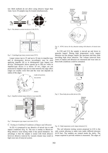
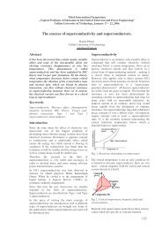
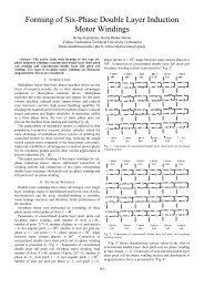
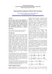
test. Both methods do not allow using abrasive larger than1mm. Up to 30 samples may be treated simultaneously.Fig. 4. Dry abrasive erosion test device CAK (TUT).Fig. 5. Centrifugal type slurry erosion tester (TUT).Larger stones (up to 25 and up to 10 mm in impeller-typeand in disintegrator devices accordingly) may be usedapplying impeller [8] or in disintegrator type impact testdevices. Disintegrator allows speeds up to 200 m/s while inimpeller-type device it is below 10 m/s. Edges are notprotected in impeller-type device that intensify the edge effect(edges are usually worn first and the wear rate depends onradius <strong>of</strong> the edge).Fig. 8. NTNU device <strong>for</strong> dry abrasion testing with abrasive <strong>of</strong> mixed sizes[9].In [10] and [11] the sample is moved up and down togenerate impact. During high temperature cyclic impactabrasion test the plunger impact the specimen and then slideproviding high stress abrasion. The volume removed <strong>for</strong>mzones <strong>of</strong> impact and abrasion are measured and wear rates inthese both conditions could be estimated.Fig. 6. Impeller-in-drum impact-abrasive wear tester [8].Fig. 9. Three-body pin-on-disk device [10].Fig. 7 Disintegrator type impact wear tester (TUT).C. <strong>Testing</strong> in Combined Conditions <strong>of</strong> Impact and AbrasionIn [9] it is proposed to use abrasive <strong>of</strong> mixed size to addimpact conditions (Fig. 8). The test is similar to Block-on-Ring abrasive wear testing while it has speed limitation. Anadvantage is that the sample is tested with fresh abrasivehowever abrasive removal by vacuum cleaner may result inhigh wear rate <strong>of</strong> removal system.Fig. 10. High temperature cyclic impact abrasion [11].The soil abrasion testing system proposed in [12] is theonly system alloying to make tests under different pressure(0-10 bar). The samples are rotated inside the slurry. Thetorque required to provide rotation is measured. The edges <strong>of</strong>302