TriTork - Triple Offset Valve
TriTork - Triple Offset Valve
TriTork - Triple Offset Valve
- No tags were found...

Create successful ePaper yourself
Turn your PDF publications into a flip-book with our unique Google optimized e-Paper software.
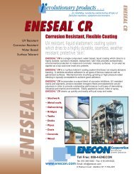
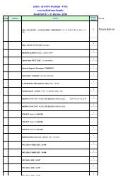
<strong>TriTork</strong> <strong>Triple</strong> <strong>Offset</strong> <strong>Valve</strong>Product Information : <strong>Valve</strong> Series | Design Features | Range | Options | Applications<strong>Triple</strong> <strong>Offset</strong> Principle<strong>Valve</strong> SeriesRange• Double flanged (Short Pattern) - TTF• 3” to 48” and larger sizes• Double flanged (Long Pattern) - TTG • Pressure rating ASME class : 150 / 300 / 600 / 900• Lug - TTL• Temperature range : -196° C to +815° C• Wafer - TTWOptions• Butt Weld - TTB• Live loaded shaft sealDesign Features• Extended bonnet for low temperature and• ‘ZERO’ leakageCryogenic applications• Bi-directional, metal to metal sealing• High temperature configuration• Low operating torque• Steam jacketing• Inherently fire safe• One piece shaft with blow-out proof designApplications• Adjustable shaft seal for low emission• Petroleum refineries• Bearing seals• Petrochemical plants• NACE compliance• Cryogenics2• Power plants• Pulp and paper• LNG storage and transportation etc.Shaftaxis13Coneaxis<strong>Triple</strong> <strong>Offset</strong> Principle<strong>Triple</strong> offset valve is a product of engineered geometrycombined with modern manufacturing techniques toachieve ‘ZERO’ leakage. The metal-to-metal,bi-directional sealing valve has non-rubbing designwhich gives less operating torque and longer servicelife.<strong>Offset</strong> 1First offset is between shaft plane and seat plane,which allows complete sealing contact around theseat.<strong>Offset</strong> 2Second offset is a distance by which shaft is displacedfrom normal to the flow line axis, thereby givingcamming effect & reduced rubbing rotation whileoperating the valve.<strong>Offset</strong> 3The seal is a segment taken from cone where apex ofthe cone is offset (3rd) from the flow line axis, whicheliminates rubbing completely.3
Product Information : Major Applications | Reference Standards | Seat Leakage ComparisonMajor ApplicationsRefinery• Fuel oil storage isolation• Steam supply stop and control• Sulphur Condenser switch• Flare gas control and isolation• Dirty hot cracking gas stop and control• FCC stop and control• Tank farmsPetrochemicals• Propane Gas• Propylene Plants• Flare Inlet & Manifold Isolation• Coker Plants• Steam Service• Ethylene PlantsPower Plant• Pump isolation• Condenser cooling• Heat exchanger, suppression system• Condensate cooling water isolation• Steam turbine generation stop and controlOthers• Hot Gas & Sour Gas (NACE)• Gas to Liquid• Abrasive Services• Process Fluids• Hydrocarbons• Liquefied Natural GasUtilities• Water Pipelines• District Storage and Distribution• High rise buildings, hotels & hospitalsReference StandardsDesign and Manufacturing API 609, ASME B16.34Face to Face / End to End API 609, ASME B16.10, ISO 5752 Series 13, ISO 5752 Series 14End ConnectionASME B16.5 for flanged end upto 24”/ASME B16.47 for larger sizes andASME B16.25 for butt weld endTestingAPI 598 Ninth EditionFire TestAPI 607 Fifth Edition, June 2005 / ISO 10497-5:2004, API 6FAFugitive Emission Testing MESC 77/312Material Conformance NACE MR 01-75Seat Leakage ComparisonHydro Seat Testing (Drops per minute)Gas Seat Testing (Bubbles per minute)<strong>Valve</strong> Size <strong>TriTork</strong> Metal Seated <strong>TriTork</strong> Metal Seated<strong>Valve</strong> (Gate & Ball) <strong>Valve</strong> (Gate &Ball)< 2" 0 0 0 02 1/2" - 6" 0 12 0 248" - 12" 0 20 0 40> 14" 0 2 / NPS 0 4 / NPSNotes: 1. Gas test is carried out using air2. For metal seated valves, allowable leakage rate values are taken from API 598 (Ninth Edition)3. As per API 598 , ‘Zero’ drops means no visible leakage per minimum specified test duration for liquid test and‘Zero’ bubbles means less than one bubble per minimum specified test duration for gas test4
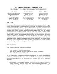
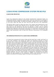
<strong>TriTork</strong> <strong>Triple</strong> <strong>Offset</strong> <strong>Valve</strong>Exploded View : Diagram | Parts List191817151491312202271121241018643522325No. Description Carbon Steel Stainless Steel1 BODY ASTM A216 Gr. WCB* ASTM A351 Gr. CF8M*1a SEAT (INTEGRAL WITH BODY) STELLITED STELLITED2 DISC ASTM A216 Gr. WCB (with ENP) ASTM A351 Gr. CF8M# #3 SEAL RING** DUPLEX+GRAPHITE DUPLEX+GRAPHITE4 RETAINER RING ASTM A516 (with ENP) ASTM A240 TYPE 3045 DISC GASKET** SPIRAL WOUND SS316+GRAPHITE SPIRAL WOUND SS316+GRAPHITE6 RETAINER SCREWS ASTM A193 Gr. B8M ASTM A193 Gr. B8M7 SHAFT ASTM A479 TYPE 410 / ASTM A182 F6a ASTM A564 TYPE 630/ASTM A276 Gr. XM 198 DISC KEY ASTM A479 TYPE 410 ASTM A564 TYPE 6309 BEARING ASTM A479 TYPE 316 (NITRIDED) ASTM A479 TYPE 316 (NITRIDED)10 SPACER ASTM A479 TYPE 316 ASTM A479 TYPE 31611 GLAND PACKING** GRAPHITE GRAPHITE12 GLAND ASTM A479 TYPE 316 ASTM A479 TYPE 31613 GLAND PLATE CARBON STEEL STAINLESS STEEL14 STUD ASTM A193 Gr. B7M ASTM A193 Gr. B8M15 NUT ASTM A194 Gr. 2HM ASTM A194 Gr. 8M16 SHAFT KEY (Not Shown) EN8 SS41017 BRACKET CARBON STEEL STAINLESS STEEL18 HEXBOLT ASTM A193 Gr. B7M ASTM A193 Gr. B8M19 NUT ASTM A194 Gr. 2HM ASTM A194 Gr. 8M20 THRUST WASHER ASTM A479 TYPE 316 (NITRIDED) ASTM A479 TYPE 316 (NITRIDED)21 STOP WASHER ASTM A479 TYPE 316 (NITRIDED) ASTM A479 TYPE 316 (NITRIDED)22 ADJUSTABLE SCREW ASTM A193 Gr. B8M ASTM A193 Gr. B8M23 BOTTOM FLANGE CARBON STEEL STAINLESS STEEL24 BOTTOM FLANGE GASKET** SPIRAL WOUND SS316+GRAPHITE SPIRAL WOUND SS316+GRAPHITE25 BOTTOM FLANGE SCREWS ASTM A193 Gr. B8M ASTM A193 Gr. B8MNote: Material conforms to the requirement of NACE MR 01-75#Solid metal seal ring can be made available on request*Other materials of construction such as Super Austenitic SS, Inconel, Duplex SS, Super Duplex SS, etc. can be madeavailable on request**Available as spares5
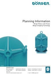
<strong>TriTork</strong> <strong>Triple</strong> <strong>Offset</strong> <strong>Valve</strong>Design Features : Low Emission Shaft Seal | Metal to Metal 'ZERO' LeakageExternally Retained Blow-Out Proof DesignDesign Features : Standard Mounting | External Indicator for Disc PositionBearing Protection | One-Piece ShaftLow Emission Shaft SealAdjustable shaft packing with multiple graphite rings sandwichedbetween two anti-extrusion rings control fugitive emission andgives longer packing life. Gland packing with live loading isavailable as an option.Standard MountingBracket top side drilling and shaft connection as per ISO 5211.Metal to Metal 'ZERO' leakageLaminated resilient seal ring flexes to give uniform wedgingeffect and ensures 'ZERO' leakage. Resiliency of seal ring allowssmall deformation in body for temperature fluctuations withoutrisk of jamming. Seal ring is retained by retainer ring and bolting.Gasket behind seal ring ensures leak proof joint.External Indicator for Disc PositionDisc position is accomplishedby dimple on shaft. When thedimple is inline with flow axis,disc is open.Integral Stellited SeatBodyDuplex SSLaminatedSeal RingDisc GasketRetainer RingDiscBearing ProtectionGraphite ring encased in bearing ensures protection againstingress of line media in to the bearing surface and thus avoidsjamming of shaft.Externally Retained Blow-Out Proof DesignEngineered gland design gives shaft blow out proof protectionexternally, conforming to the requirements of API 609. Inaddition, two screws provided at the bottom retain the shaftagainst blowout.One-Piece ShaftOne-piece shaft is guided by long bearings, which are placednearer to disc for close support. Differential expansion due totemperature is taken care by key connection between shaft &disc. Bearings are super finished and nitrided for trouble freelife. All portion of the shaft within the pressure boundary exceedin strength compare to the shaft portion outside the pressureboundary by minimum 10%.6 7
<strong>TriTork</strong> <strong>Triple</strong> <strong>Offset</strong> <strong>Valve</strong>Dimensional DetailsDouble Flanged (TTF, TTG) & Butt Weld (TTB)BACBACANSI CLASS 150Size A B C D E F ApproximateWeight (kg)TTF,TTB TTG TTF TTB80 135 275 250 114 203 45 180 29 21100 170 375 343 127 229 45 180 38 28150 185 395 363 140 267 54 240 55 39200 200 420 383 152 292 66 285 82 56250 225 465 428 165 330 76 305 109 84300 260 520 470 178 356 76 305 169 120350 315 570 528 190 381 92 320 208 151400 340 610 551 216 406 130 370 245 184450 360 680 619 222 432 120 395 285 224500 390 735 674 229 457 120 395 363 274600 500 970 914 267 508 130 381 506 410EEDDFFANSI CLASS 300Size A B C D E F ApproximateWeight (kg)TTF,TTB TTG TTF TTB80 135 370 345 114 282 45 180 35 26100 170 410 385 127 305 45 180 48 31150 220 445 413 140 403 54 240 87 62200 250 510 473 152 418 66 285 118 90250 270 550 505 165 457 76 305 145 132300 300 590 534 178 502 76 305 222 184350 350 700 638 190 762 92 320 344 248400 400 735 660 216 838 130 370 435 341450 425 830 755 222 914 120 395 588 468500 510 920 845 229 991 120 395 674 539600 600 1120 1043 267 1143 130 381 979 825ANSI CLASS 600Size A B C D E F ApproximateWeight (kg)TTF,TTB TTG TTF TTB80100 175 375 338 190 432 72 300 82 54150 225 465 423 210 559 92 320 143 94200 275 610 548 230 660 120 395 245 169250 330 675 613 250 787 130 381 345 232300 350 715 640 270 838 175 410 501 362350 390 810 735 290 889 175 410 594 443400 420 870 795 310 991 220 442 745 569450 480 975 880 330 1092 170 480 910 720500 530 1060 920 350 1194 195 571 1282 885600 645 1240 1095 390 1397 210 729 1730 1240Notes• All dimensions are in mm• Class 150 & 300 : Face to face dimensions for Double Flanged - short pattern (TTF) & End to End for butt weld (TTB) areas per ISO 5752 Basic Series 13• Class 600 : Face to face dimensions for Double Flanged - short pattern (TTF) & End to End for butt weld (TTB) are as perISO 5752 Basic Series 14• Face to face dimensions for Double Flanged - long pattern (TTG) are as per ASME B16.10 Gate <strong>Valve</strong>s• Above dimensions are for reference only9
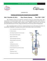
Technical Details : Shaft Side Torque Values | Pressure-Temperature RatingShaft Side Torque ValuesANSI #150ΔP 20 barOpeningClosing3" 4" 6" 8" 10" 12" 14" 16" 18" 20" 24”Nm 75 112 197 359 642 969 1284 1797 2360 2859 4583in-lbs 662 994 1741 3178 5685 8580 11368 15902 20891 25300 40565Nm 68 94 157 213 407 590 671 985 1208 1304 1846in-lbs 606 832 1390 1885 3603 5219 5939 8718 10692 11541 16338RunningNm 41 46 49 90 146 184 246 291 366 397 520in-lbs 363 407 434 797 1292 1629 2177 2576 3239 3514 4602ANSI #300ΔP 50 barOpeningClosing3" 4" 6" 8" 10" 12" 14" 16" 18" 20" 24”Nm 130 201 448 879 1492 2159 2701 4633 5273 6856 10654in-lbs 1152 1779 3965 7780 13205 19109 23906 41006 46670 60681 94296Nm 115 172 297 453 805 1189 1372 1810 2294 2453 3522in-lbs 1018 1522 2629 4009 7125 10524 12143 16020 20304 21711 31172RunningNm 62 74 145 279 352 451 551 782 906 1198 1456in-lbs 549 655 1283 2469 3115 3992 4877 6921 8019 10603 12887ANSI #600ΔP 100 barOpeningClosing3" 4" 6" 8" 10" 12" 14" 16" 18" 20" 24”Nm -- 592 1444 2521 4375 6389 7611 11256 20508 26345 35603in-lbs -- 5240 12780 22313 38722 56547 67363 99624 181511 233173 315113Nm -- 406 589 1456 2153 2946 3614 4156 6536 8870 9558in-lbs -- 3593 5213 12887 19056 26074 31987 36784 57849 78506 84595RunningNm -- 164 311 526 643 915 1123 1444 3858 4973 8010in-lbs -- 1452 2753 4655 5691 8098 9939 12780 34146 44015 70895Notes• Torque values are for laminated duplex + graphite seal ring and stellited seat• Torque values are at ambient temperature with media being clear water and without factor of safety• Consider factor of safety as 30% on above mentioned torque values• Torque values for larger sizes can be provided on requestPressure-Temperature Rating (As per ASME B16.34)16001400Pressure (PSI)120010008006004002000100 200 300 400 500 600 700 800 900 10000Temperature ( F)WCB # 150WCB # 300WCB # 600CF8M # 150CF8M # 300CF8M # 60010
Virgo Engineers Group - <strong>TriTork</strong> DivisionEuropeVirgo Europe SpaVia delle Orchidee 720020 Vanzaghello - Milan - ItalyPhone: +39 0331 308211Fax: +39 0331 306299Middle East and AfricaVirgo <strong>Valve</strong>s & Controls (ME) FZEUnit - FZS1 AH07, Jebel Ali Free Zone,P.O Box - 18748, Dubai - UAEPhone: +971-4-8860980Fax: +971-4-8860981Indian Sub-continentVirgo Engineers Limited277, Hinjewadi Phase II, Maan (Mulshi),Pune - 411 057, IndiaPhone: +91 20 66744000Fax: +91 20 66744021North and South AmericaVirgo Engineers Inc.10225 Mula Road, Suite 130Stafford, TX – 77477, USAPhone: +1 281 933 3100Fax: +281 933 3110Far East AsiaVirgo <strong>Valve</strong>s & Controls LimitedSuite 1904, 19th Floor, Kenanga International,Jalan Sultan Ismail, 50250 Kuala Lumpur, Malaysia.Phone: +60 3 2161 8260Fax: + 60 3 2166 6489Contact us:sales@tritork.comwww.tritork.comTechnical specifications are subject to changeTOV : 2009/11 R3