Tube Diffuser - Jäger Umwelt-Technik GmbH & Co. KG
Tube Diffuser - Jäger Umwelt-Technik GmbH & Co. KG
Tube Diffuser - Jäger Umwelt-Technik GmbH & Co. KG

You also want an ePaper? Increase the reach of your titles
YUMPU automatically turns print PDFs into web optimized ePapers that Google loves.
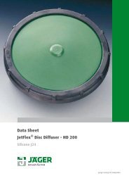
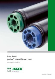
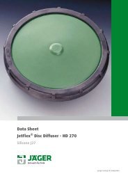
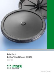
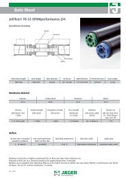
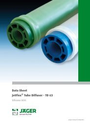
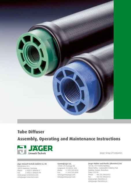
Specifications1. Aeration SystemsThis manual describes in detail the installation and operating of tube diffuser JetFlex TD 63/0 withperforation lenghts of 500, 750 and 1000 mm, respectively.2. General<strong>Jäger</strong> <strong>Umwelt</strong>-<strong>Technik</strong> <strong>GmbH</strong> & <strong>Co</strong>. <strong>KG</strong> (JUT) supplies diffuser for diffused air aeration in residential andindustrial waste water treatment plants.The diffusers deliver fine bubble aeration suitable for the efficient treatment of wastewater treatmentplants using the activated sludge process. Specially formulated EPDM compounds with high anddurable elasticity allow a long-term intermittent operation needed to apply the de-nitrificationprocess.The treatment of industrial wastewater (typically a share of more than 10% in residential wastewateris considered to be industrial wastewater) may require the use of different materials like Silicone,Nitrile, Viton ® or PUR. <strong>Co</strong>ntact JUT for details.JUT controls every step from compounding to final assembly and documents the conformance of thediffusers to your requirements. All diffusers are factory-assembled and ready to install. Please treatdiffusers carefully during transport, storage and assembly.Our General <strong>Co</strong>nditions of Sale apply to all shipments; the actual issue can be downloaded from ourwebsite at any time. www.jaeger-envirotech.com3. ShipmentWe ship diffusers in cardboard boxes. See individual data sheets for packaging details.4. Incoming InspectionUpon arrival check packages, equipment and products for structural damage during shipments, particularlythe rubber membranes and stainless steel clamps. Any damage must be reported to JUT and/or shipping agent within 5 working days from delivery. JUT reserves the right to inspect damagedshipments. Warranty applies to products in their original and intact packing only!5. Storage of Equipment• Store equipment and diffusers as well as all accessories in their original packaging in a dryand aerated room according to DIN 7716 or ISO 2230.• Prevent products from frost, excessive heat, direct sunlight, UV emitting lamps, dust, mineral oiland hydrocarbons.• Do not store near electrical motors, especially blowers.• Avoid work that may damage the diffusers or their packaging.• Do not store outdoors! Storage time until installation/start up operation should not exceed oneyear. <strong>Co</strong>nsult JUT for precautions otherwise.• On the construction site all parts must remain in their original packaging and protected fromrain, moisture etc. Open crates exposed to direct sunlight must be covered with tarpaulin toprotect against UV-radiation.• Do not use packaging material containing plasticizers.
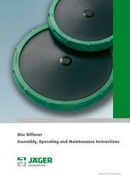
Specifications6. Assembly6.1 Preparations• Prior to assembly of the aeration system remove all debris (stones, metal scrap, wooden piecesetc.) from the aeration tank.• Stainless steel square tubes (80 x 80 mm or 100 x 100 mm) are recommended as laterals forJetFlex TD 63/0 diffusers with SS-connectors.• Standard round lateral tubing require the use of a special clamp. See TD 65/2 data sheet.• All laterals must be levelled within ± 6.35 mm (± 1/4”) for proper function of diffusers.• Air outlet holes in lateral for each diffuser must be predrilled and adjusted in accordance to theindividual data sheets. Hole diameter ± 0.1 mm, horizontal alignment of holes within ± 0.5 mm.• Do not drill holes within welded area of tubing.• Deburr all holes.• Remove all corroded spots etc.• Remove all internal debris from within the laterals with a water flush through the laterals.6.2 <strong>Diffuser</strong> Alignment• Align diffusers longitudinal to the water flow.• Keep enough distance to water accelerators (propellers etc.). Water velocity at diffusers must notexceed 0.5 m/s.• If water speed is perpendicular to the diffusers use additional fixtures or reduce diffusers lengthto avoid breaking of the plastic tubes. <strong>Co</strong>ntact JUT for details.6.3 Installation (type 63/0 only)This type of diffuser is installed in pairs. To ease tightening the gaskets may be wetted with alubricant. Recommended lubricants are commercial-grade water-based soap (5 - 10%) or regularhousehold detergents (0.01 - 0.1%). Do not use lubricants containing mineral oils or otherhydrocarbons.• Screw the connector into one diffuser and slip one gasket over the connector.• Slide the free end of the connector through both holes of the lateral an put on the secondgasket.• Thread the second diffuser onto the connector and tighten both diffusers just lightly by hand.• Tighten both units an additional 1/2 to 3/4 turn with two fork wrenches. Across-flats measure is55 mm.• Do not twist the rubber membrane of the diffuser.• Both gaskets should be equally deformed.• The non-perforated strips of the diffusers are now on top and bottom.
Specifications7 Operating Instructions7.1 Start-Up InstructionsPrior to start-up clean the aeration tank from debris like stones, wooden pieces, metal parts etc.Keep the time between assembly and filling of the basin as short as possible. Ohterwise take thefollowing steps:• Do not perform any work near the diffuser or above the aeration tank, which may damagediffusers; e.g. painting, welding, concrete sealing etc.• Safeguard diffusers from falling parts.• Fill tank with clean water approximately 20 cm above diffusers. Start blowers for 5 - 10minutes and check for obvious leaks. Have blowers stopped and immediately check again for smaller andhidden leaks when airflow seizes. Tiny leaks may be detected now with lower turbulences.• Start wastewater treatment now or raise water level to 1 m with clean water.• Operate blowers for 10 minutes at medium speed at least once a day.• Raise water level even more if temperatures drop below freezing. (~20 cm additional water foreach degree Celsius below zero.)• Prior to SOTE testing allow diffusers to run at maximum design airflow for one week (minimum 3days).7.2 Regular OperationDuring regular operation adjust airflow of diffusers to maintain the required oxygen level in theaeration tank. Keep airflow within recommended range of diffusers (see data sheets).Too high an airflow reduces efficiency and may eventually damage the diffuser membraneirreversibly. Very low airflow rates may cause uneven oxygen supply and excessive fouling of themembrane surface. Water temperature should range from 5 °C to 35 °C; air temperature at the diffusershould not exceed 60 °C. <strong>Co</strong>nsult JUT in case either temperature is higher.Air from blowers must not contain oil, dust, or solvents. Use dust filters according to DIN EN 779 (>80%,better >90% dust removal, class G3 or G4, respectively.) Air going into the blowers must correspondto local regulations (see e.g. TA-Luft for Germany).<strong>Diffuser</strong> headloss should be monitored continuously. An increase of more than 20 mbar/year may indicatea clogging problem caused by deposits of carbonates, iron-salts, or biological growth. See section7.4 for details of cleaning. Inspect diffusers visually on a regular basis at least once a year.
Specifications7.3 Trouble ShootingJetFlex <strong>Diffuser</strong>s need very little maintenance even for long-term operation due to theirhigh-performance materials. JUT recommends regular inspection intervals every 12 to 18 months inorder to monitor fouling processes. Check pressure loss permanently with accurate pressure gauges,an increase of more than 20 mbar per year may indicate fouling or other problems.The most common problems and their recommended corrections are:1. Indication: Large volume of air in localized areaPossible cause: Leakage in lateral pipingProcedure: Drain basin to access area in question, maintain medium air flow, checkconnectors and pipes for evidence of breakage, repair or exchangePossible cause: <strong>Diffuser</strong> membrane is damaged or missingProcedure: Drain basin to access area in question, maintain medium air flow, inspectvisually diffuser, exchange membrane or complete diffuser2. Indication: Non uniform bubble patternPossible cause: Insufficient blower capacityProcedure: <strong>Co</strong>nfirm blower operations, switch on additional blowersPossible cause: Check valve of drop lines closed or not open enoughProcedure: Inspect position of check valvePossible cause: Incomplete air distribution to diffusersProcedure: Drain basin to access area in question, check diffuser horizontal levelling,level within tolerance of ± 0,6 cm / ± 1/4”, inspect piping and joints for internalclogging from debris, air purge or water flush cleaningPossible cause: Deposits on diffuser membraneProcedure: Inspect diffuser membranes for deposits and encrustation, clean or exchangemembrane or exchange diffuser3. Indication: Decreasing of dissolved oxygen level, increase of system pressure dropPossible cause: Deposits on diffuser membraneProcedure: Inspect diffuser membranes for deposits and encrustation, clean or exchangemembrane or exchange diffuser4. Indication: Non uniform dissolved oxygen profile throughout basinPossible cause: Insufficient air volumeProcedure: <strong>Co</strong>nfirm blower operations, switch on additional blowers, check equipmentand operation conditions, see 1-3Depending on type of waste, individual constructions and operation conditions other causes can leadto disturbances. If necessary contact the contractor or engineering office.
Specifications• Check if air outlets of diffuser tube are pointing up/downwards. Adjust position if necessary, seechapter 6.3 for details. Use new gaskets!• Push membrane over tube. <strong>Co</strong>mpare both non-perforated ends, and slide the longer zone firstonto the plastic tube, it should cover the coloured zone of the tube. Both non-perforated stripsalong the membrane must face exactly up/downwards.• Pull new clamps over the sleeve and adjust them at the proper position on both ends of thediffuser. Use spare diffusers from JUT to locate the optimum position of clamps.• Use special pair of nippers (JUT # 12001) to close the clamp. The gap of the ear should notexceed 2 mm after closure (recommended are 1.0 to 1.5 mm).• Fold ends of sleeves over clamp.• Run leak-test as described in chapter 7.1.8.2. Replacing <strong>Tube</strong> <strong>Diffuser</strong>• Remove sludge from diffusers with pressure-washer.• Unscrew diffuser with two fork-wrenches of 55 mm width.• Clean sealing area and connector, use new gaskets.• Mount new diffusers as described in chapter 6.3.• Run leak-test as described in chapter 7.1.9. RecyclingObserve all local and federal regulations for waste deposit at time of disposal. Clamps may be disposedof as scrap metal. In case of contamination check with authorities and/or a certified wastemanagement consultant.10. DisclaimerThis information is based on our present state of knowledge and is intended to provide generalnotes on our products and their uses. It should not therefore be construed as guaranteeing specificproperties of the products described or their suitability for a particular application. US units are forconvenience only. Any existing industrial property rights must be observed. The quality of our productsis guaranteed under our General <strong>Co</strong>nditions of Sale.11. Reference• DIN 7716, Erzeugnisse aus Kautschuk und Gummi, Anforderungen an die Lagerung, Reinigungund Wartung, Beuth Verlag, Berlin 1982.• TA Luft, Technische Anleitung zur Reinhaltung der Luft, 1986.• DWA-M 115, Indirekteinleitung nicht häuslichen Abwassers, DWA, Hennef, 2004• ATV M-209, Messung der Sauerstoffzufuhr von Belüftungseinrichtungen in Belebungsanlagen,in Reinwasser und in belebten Schlamm, Gesellschaft zur Förderung der Abwassertechnik e.V.(GFA), Hennef 1996.• PrEN 12255-15, Wastewater treatment plants - Part 15: Measurement of the oxygen transfer inclean water in activated sludge aeration tanks, European <strong>Co</strong>mmittee For Standardization, Brussels,1999. ANSI/ASCE 2-91, Measurement of Oxygen Transfer in Clean Water, American Society of CivilEngineers, New York, 1992.JUT_2007_04